WO2014097856A1 - 現金自動預け払い機 - Google Patents
現金自動預け払い機 Download PDFInfo
- Publication number
- WO2014097856A1 WO2014097856A1 PCT/JP2013/082122 JP2013082122W WO2014097856A1 WO 2014097856 A1 WO2014097856 A1 WO 2014097856A1 JP 2013082122 W JP2013082122 W JP 2013082122W WO 2014097856 A1 WO2014097856 A1 WO 2014097856A1
- Authority
- WO
- WIPO (PCT)
- Prior art keywords
- toothed
- belt
- roller
- path
- conveying
- Prior art date
- Legal status (The legal status is an assumption and is not a legal conclusion. Google has not performed a legal analysis and makes no representation as to the accuracy of the status listed.)
- Ceased
Links
Images








Classifications
-
- G—PHYSICS
- G07—CHECKING-DEVICES
- G07D—HANDLING OF COINS OR VALUABLE PAPERS, e.g. TESTING, SORTING BY DENOMINATIONS, COUNTING, DISPENSING, CHANGING OR DEPOSITING
- G07D11/00—Devices accepting coins; Devices accepting, dispensing, sorting or counting valuable papers
- G07D11/10—Mechanical details
-
- B—PERFORMING OPERATIONS; TRANSPORTING
- B65—CONVEYING; PACKING; STORING; HANDLING THIN OR FILAMENTARY MATERIAL
- B65H—HANDLING THIN OR FILAMENTARY MATERIAL, e.g. SHEETS, WEBS, CABLES
- B65H2404/00—Parts for transporting or guiding the handled material
- B65H2404/20—Belts
- B65H2404/26—Particular arrangement of belt, or belts
- B65H2404/262—Arrangements of belts facing rollers
Definitions
- the present invention relates to an automatic teller machine, for example, an automatic teller machine that uses a toothed belt in a paper sheet transport mechanism having a branch transport path in the middle of a transport path and uses both a bill transport and power transmission.
- Patent Document 1 Japanese Patent Laid-Open No. 2002-230621
- Patent Document 1 discloses a paper sheet transport mechanism that transports paper with a toothed belt and a roller sandwiched between them.
- the paper sheet transport mechanism described in Patent Document 1 is configured to transport only banknotes using a toothed belt and a roller, and there is no description of transmitting power to another transport path using a toothed belt.
- An object of the present invention is to provide a small and highly reliable cash which uses a toothed belt for a paper sheet transport mechanism having a second transport path that branches from the middle of the first transport path, and is used for both bill transport and power transmission.
- the purpose is to provide an automated teller machine.
- the present application includes a plurality of means for solving the above-mentioned problems.
- a pulley with a drive tooth that is driven to rotate a pulley with a driven tooth that is driven to rotate, and a pulley with a tooth that is driven and rotated.
- an automatic teller machine provided with a paper sheet transport mechanism having a first transport path for sandwiching and transporting paper sheets, the first transport path meshes with teeth of the toothed belt in order from the upstream side.
- Transport rollers and the toothed base A second toothed pulley that meshes with the teeth of the tooth and presses the toothed belt; a second conveying roller provided opposite to the second toothed pulley; and a rotation shaft of the second conveying roller A flat belt wound around the second conveying roller and the third conveying roller at the other end, and the second gear provided to face the third conveying roller.
- a second conveying path that includes a pressing roller that presses the flat belt, and holds and conveys paper sheets between the flat side of the toothed belt and the flat belt, and between the flat belt and the pressing roller.
- a gate for branching the paper sheet from the first conveyance path to the second conveyance path provided downstream of the second conveyance roller, and the toothed belt of the first conveyance path Via the first gear rotating at the first gear and the second gear meshing with the first gear. And providing a paper sheet conveyance mechanism for rotationally driving the second conveyance path of Te.
- the first conveying path presses the first toothed pulley meshed with the teeth of the toothed belt in order from the upstream side, and the toothed belt provided facing the first toothed pulley.
- a first conveying roller, a second toothed pulley that meshes with the teeth of the toothed belt and presses the toothed belt, and a second conveying roller provided to face the first toothed pulley A flat belt wound around the second conveying roller and the third conveying roller at the other end, and a pressing roller for pressing the flat belt provided to face the third conveying roller
- a second transport path for transporting paper sheets while sandwiching the sheet between the flat belt side of the toothed belt and the flat belt, and between the flat belt and the pressing roller, and the second transport Provided on the downstream side of the roller, the second transport from the first transport path
- the one toothed belt and the toothed pulley are arranged in the center in the width direction of the first conveying path, and the first conveying path is provided on the rotation shaft of the first toothed pulley.
- a gate that is provided on the downstream side of the second transport roller and branches the paper sheets from the first transport path to the second transport path.
- a paper sheet transport mechanism that drives and rotates the second transport path via the first gear rotated by a toothed belt and the second gear meshing with the first gear is provided. .
- the one toothed belt and the toothed pulley are arranged in the center in the width direction of the first conveying path, and the first conveying path is provided on the rotation shaft of the first toothed pulley.
- a paper sheet transport mechanism that rotates the power transmission roller with a toothed belt of the first transport path and drives and rotates the second transport path.
- first toothed pulley and the second toothed pulley are arranged so that the positions of the outer periphery of the first toothed pulley and the outer periphery of the second toothed pulley are different, It is characterized in that a paper sheet transport mechanism is provided that allows the toothed belt to undulate.
- a sheet conveyance mechanism is provided on the toothed belt as the flat belt of the second conveyance path.
- flanges are provided on both sides of the roller around which the flat belt of the second conveyance path is wound, and the roller is rotated by bringing the flat side of the toothed belt of the first conveyance path into contact with the flange.
- the paper sheet conveying mechanism is provided so as not to contact the flat side of the toothed belt with the flat belt.
- the first transport path is divided into an upper transport section including a toothed belt and a lower transport section, and a paper sheet transport mechanism is provided so as to release the first transport path.
- first conveying path that conveys the paper sheet with a toothed belt and a conveying roller
- second belt that conveys the paper sheet with a flat belt that branches from the middle of the first conveying path and the conveying roller.
- a paper sheet transport mechanism that drives and rotates the flat belt of the second transport path via a gear that rotates with the toothed belt of the first transport path.
- a small and highly reliable cash that uses a toothed belt for a paper sheet transport mechanism having a second transport path that branches from the middle of the first transport path and uses both a bill transport and power transmission.
- An automated teller machine can be provided.
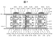
- FIG. 3 is a plan view of the lower transport unit 16 in FIG. 2 viewed from the B direction.
- FIG. 1 is a side view showing the overall configuration of the automatic teller machine 1.
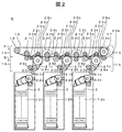
- FIG. 2 is a side view showing a part of the paper sheet transport mechanism 9 using the toothed belt of the present invention.
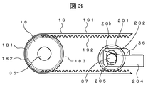
- FIG. 3 is a side view showing the structure of the toothed belt and the toothed pulley of FIG.
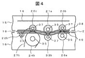
- FIG. 4 is an enlarged side view of the upper transport unit 15 and the lower transport unit 16 in which the transport path of FIG.
- FIG. 5 is an enlarged side view of the upper transport unit 15 and the lower transport unit 16 having a flat transport path in FIG.
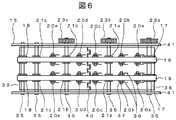
- FIG. 6 is a plan view of the upper transport unit 15 in FIG. 2 as viewed from the A direction.
- FIG. 7 is a plan view of the lower transport unit 16 in FIG. 2 as viewed from the B direction.
- An automatic teller machine 1 in FIG. 1 includes a banknote handling port 3 for depositing and dispensing banknotes 2, a transporting roller 4 for transporting banknotes 2, a transport path 5 (shown in bold lines) for banknotes 2, and banknotes.
- a discriminator 6 for determining the denomination or authenticity of No. 2, a temporary stacker 7 for temporarily storing the bill 2 when the bill 2 is stored and dispensed, a gate 8 for switching the destination of the bill 2, and the present invention.
- the sheet transport mechanism 9 using the toothed belt of the embodiment, the banknote collection box 10 for storing the banknote 2 that cannot be mechanically processed, and the reflux box 12a for storing and dispensing the banknote 2 by denomination To 12e.
- the banknotes 2 supplied to the banknote handling port 3 are separated one by one and supplied to the conveyance path 5.
- the discriminator 6 it is discriminated whether the bill 2 is denominated as a genuine note or a fake note, and whether or not two or more bills 2 are overlapped.
- the banknote 2 is a genuine note and is a single note or a folded note, it is stored in the temporary stacker 7 and the transaction amount is displayed.
- all the supplied banknotes 2 are returned to the banknote handling port 3.
- the transaction passes through the discriminator 6 again to check whether two or more denominations of the banknote 2 overlap.
- the banknotes 2 are branched into denominations by the paper sheet transport mechanism 9 and stored in the respective recirculation cabinets 12a to 12e.
- the banknotes are dispensed, the banknotes 2 in the reflux cabinets 12a to 12e are separated one by one and supplied to the paper sheet transport mechanism 9.
- the discriminator 6 it is determined whether or not two or more banknotes 2 overlap. When there is only one bill 2, it is paid out to the bill handling port 3.
- two or more sheets are overlapped or folded, they are stored in the temporary stacker 7 and then stored in the banknote collection box 10.
- FIG. 2 shows a paper sheet transport mechanism 9 using a toothed belt, and denomination reflux boxes 12a, 12b, and 12c.
- the paper sheet transport mechanism 9 is composed of an upper transport section 15 composed of a toothed belt 19 and a lower transport section 16 composed of a roller. Note that the lower conveyance unit 16 can rotate downward about the R-R ′ of the casing 49 in FIG. 7 to release the conveyance path for maintenance and inspection such as jam removal.
- the upper transport unit 15 has a rotating shaft 35 fixed to the housing 41 via a bearing 41 and a toothed pulley 17 that is driven to rotate by a predetermined rotation driving device, and the rotating shaft 35 via the bearing 41.
- the toothed belt 19 for pressing the toothed belt 19 against the pulleys 24, 24a, 24c, 26a, 26b of the lower conveying section 16 Movable toothed pressure pulleys 20a-20e, toothed pulleys 17, 18, 21a, 21b, 21c, toothed belt 19 wound around toothed pressure pulleys 20a-20e, and toothed pulleys 17, 21a, It is comprised with the gearwheels 23a, 23b, 23c provided in the rotating shaft 35 of 21b.
- the conveyance path is waved to improve the pressing force between the toothed belt and the roller, and the bill 2 is deformed to improve the rigidity.
- the outer circumferences of the toothed pulleys 21a and 21b are arranged so as to be located below the outer circumferences of the rollers 24a, 24b, 24c, 26a and 26b of the lower transport section 16.
- two toothed pulleys 17, 18, 21a, 21b, 21c and two toothed pressure pulleys 20a to 20e are provided in the width direction of the conveying path, and are arranged linearly in the conveying direction.
- Two toothed belts 19 are wound around.
- the lower transport unit 16 fixes rollers 24 a, 24 b, 24 c to which a rotating shaft 35 is fixed to a housing 49 via a bearing and power is transmitted by a toothed belt 19 to be rotated, and a rotating shaft 35.
- Rollers 26a, 26b fixed to the housing 49 via bearings and driven to rotate, and the toothed pulleys 17, 21a, 21a, 21b, 21c of the upper transport section 15 are provided to press the toothed belt 19.
- Comb teeth in which pressing rollers 33a to 33d movable in the direction of the toothed belt 19 and a rotating shaft 35 for branching the banknote 2 being conveyed to the recirculation cabinets 12a, 12b, 12c are fixed to the housing 49 via bearings.
- the rollers 24a, 24b, and 24c rotate the toothed pulleys 21a, 21b, and 21c by the movement of the toothed belt 19 of the upper conveyance unit 15, and the gears 23a, 23b, and 23c, and the gears 25a, 25b, and 25c, respectively. Is rotated.
- the guides 30a, 30b, 30c can move in the direction of the reflux containers 12a, 12b, 12c. When moving to take out the reflux containers 12a, 12b, 12c to the outside, they are retracted to a position where they do not hit the reflux containers 12a, 12b, 12c. As shown in FIG.
- Refrigeration warehouses 12a, 12b, and 12c are provided with banknote entry / exit ports 31a, 31b, and 31c, banknote separation / stacking mechanisms 32a, 32b, and 32c for separating and feeding banknotes 2 one by one or storing banknotes 2; Consists of storage units that accumulate.
- the banknote 2 is conveyed from the right direction.
- the banknote 2 is sandwiched and transported by the flat belts 27a, 27b, 27c of the lower transport unit 16 and the rollers 26a, 26b and the pressing rollers 33a-33d, which are arranged to face the toothed belt 19 of the upper transport unit 15.
- the banknote 2 is branched in the direction of the reflux box 12b by closing the conveyance path with the gate 22b.
- the reflux cabinet 12b collects the taken banknotes 2 in the storage unit by the banknote separating and accumulating mechanism 32b.
- the banknotes 2 are separated one by one by the banknote separating and accumulating mechanism 32b of the reflux box 12b, and are conveyed rightward through the same route as when stored.
- the gate 22 b is retracted below the guide 45 when the banknote 2 is allowed to pass, and moves to the upper side of the guide 38 to block the conveyance path when the banknote 2 is branched.
- the first conveyance path and the second conveyance path are prevented from changing in the conveyance speed due to disturbance such as load fluctuation.
- a separate power transmission mechanism is provided for rotationally driving the conveyance path. Therefore, in the embodiment of the present invention, the first transport path sandwiches and transports the banknotes by the roller side of the rotationally driven toothed belt and the roller, and rotates from the toothed side of the toothed belt to the second transport path. Try to transmit power. Thereby, since conveyance of a bill and transmission of driving force can be performed only with a toothed belt, the conveyance mechanism can be downsized. Furthermore, it is effective for cost reduction.
- FIG. 3 shows an embodiment of the toothed belt 19, the toothed pulley 18 and the toothed pressing pulley 20b shown in FIG.
- the toothed pulley 18 in FIG. 3 includes a peak portion 181 and a valley portion 182 showing a pulley tooth type, a flange 183 provided on a side surface, and a rotating shaft 35.
- the outer periphery of the flange 183 is set lower than the outer periphery of the toothed belt 19 so as not to contact the banknote 2. As a result, even if the toothed belt 19 meanders, the side surface of the toothed belt 19 comes into contact with the flange 183 so that the toothed belt 19 does not come off from the toothed pulley 18.
- the toothed pulley 17 has a similar configuration.
- Reference numeral 191 denotes a planar side of the toothed belt
- reference numeral 192 denotes a toothed side of the toothed belt.
- the toothed pressing pulley 20b includes a peak portion 201 and a trough portion 202 indicating a pulley tooth type, a rotating shaft 37 of the toothed pulley 20b, a spring 36 pressing both ends of the rotating shaft 37, and a pulley mounting plate 204. Both ends of the rotating shaft 37 of the toothed pulley 20 b are inserted into elliptical bearings 205 of the pulley mounting plate 204, and both ends of the rotating shaft 37 are pressed by the springs 36.
- the toothed pulley 20b can be moved and pressed in the direction of the toothed belt 19 by the spring 36.
- the pressing toothed pulley 20b can eliminate the flange.
- the other toothed pressure pulleys 20a to 20e have the same configuration.
- the toothed pulleys 21a and 21b have the same configuration as the toothed pulley.
- the pressing rollers 33a to 20d of the lower conveying section 16 have the same configuration if a toothed pulley is used as the roller, and the pulley mounting plate 204 is fixed to the guides 45 and 46 shown in FIG.
- FIG. 4 shows a partially enlarged view of an embodiment of the upper transport unit 15 and the lower transport unit 16 in which the transport path of FIG. Other parts are shown in parentheses because they have the same structure.
- the outer circumference of the toothed pulley 21 a (21 b) is arranged so as to be positioned below the outer circumference of the rollers 26 a (26 b) and the rollers 24 b (24 c) of the lower transport unit 16.
- the toothed pulley 21a (17, 21b, 21c) and the toothed pressure pulleys 20b, 20c (20a to 20e) of the upper transport unit 15 are provided with through holes in the guide 38 (39), and the toothed pulley is located on the transport path side.
- the toothed pressing pulleys 20b and 20c (20a to 20e) are provided on the guide 38 (39).
- the rollers 24b and 26a (24a, 24c and 26b), the pressing rollers 33b (33a to 33d), and the gate 22b (22a and 22c) of the lower transport unit 16 are provided with through holes in the guide 45 (46). It is provided so that the outer peripheral part of a roller may be exposed to the conveyance path side.
- the gate 22b (22a, 22c) is retracted below the guide 45 (46) when the bill 2 is allowed to pass, and is moved above the guide 38 (39) when the bill 2 is branched to block the conveyance path. To work.
- the pressing rollers 33a to 33d are provided on the guide 45 (46). Even when the lower conveying section 16 is rotated downward and the conveying path is released during maintenance, the toothed pressure pulleys 20a to 20e move and the tension of the toothed belt does not relax. Therefore, even if an external force such as a hand is applied, it is difficult to come off from the toothed pulley.
- the conveying path is waved and the pressing force of the toothed belt 19, the roller 26a (26b) and the flat belt 27b (27c) of the roller 24b (24c) is improved, and the bill 2 is deformed and the rigidity is improved, so that an jam or the like does not occur.
- FIG. 5 shows a partially enlarged view of an embodiment of the upper transport section 15 and the lower transport section 16 in which the transport path of FIG. FIG. 5 has the same configuration as that of FIG.
- the outer periphery of the toothed pulley 21 a (21 b) is arranged at the same position as the outer periphery of the rollers 26 a (26 b) and the rollers 24 b (24 c) of the lower transport unit 16. Thereby, a conveyance path is made into a plane.
- the guides 38 and 45 have a flat shape, thereby facilitating manufacture. Even if the lower conveying section 16 is rotated downward to release the conveying path during maintenance, the tension of the toothed belt does not loosen, so that it is difficult to come off the toothed pulley even if an external force such as a hand is applied.
- FIG. 6 shows a plan view of the upper conveyance unit 15 of FIG. 2 as viewed from the A direction.
- the same reference numerals as those in FIGS. 2 to 5 are omitted.
- the upper transport unit 15 has a housing 41, a toothed pulley 17 fixed to the housing 41 through a bearing and rotationally driven by a predetermined rotation driving device, and a rotating shaft 35 fixed to the housing 41 through a bearing.
- the toothed pulleys 18, 21 a, 21 b, 21 c that are driven and rotated, and can be moved in the direction of the toothed belt 19 for pressing the toothed belt 19 against the rollers 24 a, 24 b, 24 c, 26 a, 26 b of the lower transport unit 16.
- Gears 23 a, 23 b, 23 c provided on the rotary shaft 35 and guides 38, 39 are included.
- one end of the spring 36 is fixed to the pulley mounting plate 204, and the pulley mounting plate 204 is fixed to the guides 38 and 39.
- the guides 38 and 39 are divided at the end 40.
- the end portion 40 has a shape in which comb teeth are engaged with each other, so that the banknote 2 is not caught.
- FIG. 7 shows a plan view of the lower transport unit 16 in FIG. 2 as viewed from the B direction.
- the same reference numerals as those in FIGS. 2 to 5 are omitted.
- the upper transport section 16 has a housing 49, rollers 24a, 24b, and 24c that are driven and rotated by the toothed belt 19 by fixing the rotating shaft 35 to the housing 49 through bearings, and the rotating shaft 35 through the bearings.
- rollers 26a, 26b fixed to the housing 49 and driven to rotate, and the toothed belt for pressing the toothed belt 19 provided opposite to the toothed pulleys 17, 21a, 21a, 21b, 21c of the upper transport section 15 Pressure rollers 33a to 33d movable in 19 directions, and gates 22a, 22b in which a rotating shaft 35 for branching the conveyed banknote 2 to the reflux stores 12a, 12b, 12c is fixed to the housing 49 via bearings, 22c, flat belts 27a, 27b, 27c wound around rollers 24a, 24b, 24c, respectively, for transporting the branched banknotes 2 to the recirculation cabinets 12a, 12b, 12c, and rollers 24a 24b, the gear 23a of the upper conveying portion 15 provided on the rotating shaft 35 of the 24c, 23b, 23c and mating gears 25a, 25b, consisting of 25c.
- one end of the spring 36 is fixed to the pulley mounting plate 204, and the pulley mounting plate 204 is fixed to the guides 45 and 46.
- the guides 45 and 46 are divided at the end 47.
- the end portion 47 has a shape in which comb teeth are engaged with each other, so that the bill 2 is not caught.
- FIGS. 8, 9, will be described with reference to FIG. 10.
- 8, 9, and 10 omit the gears 23 b and 23 c of the upper transport unit 15 shown in FIGS. 2, 6, and 7, and the gears 25 a, 25 b, and 26 c of the lower transport unit 16 fitted to the gears. It is a configuration.
- the same reference numerals as those in FIG. 2, FIG. 6, and FIG. 8, 9, and 10 show power transmission from the toothed belt 19 of the upper transport unit 15 to the flat belts 24 a, 24 b, and 24 c from the toothed belt 19 to the lower transport unit 16. In this configuration, the frictional force is 24c.
- the toothed belt 19 is swung to increase the pressing force between the toothed belt 19 and the flat belts 24a, 24b, 24c, thereby improving the frictional force and eliminating the occurrence of slipping. be able to.
- the frictional force is improved and the occurrence of slippage can be eliminated by increasing the pressing force of the toothed pressing pulleys 20a, 20c, 20e.
- the first conveying path sandwiches and conveys the banknotes between the plane side of the toothed belt that is rotationally driven and the roller, and also conveys the plane side of the toothed belt and the second conveyance.
- Rotational power is transmitted by contacting the conveyor belt of the road.
- the conveyance mechanism can be downsized. Furthermore, it is effective for cost reduction.
- the power is transmitted by the toothed belt, there is no slip, so that the transport speed of the first transport path and the second transport path can be made the same, and there is no energy loss, so energy saving can be achieved.
- there is no speed difference between the right and left toothed belts there is no skew in which the posture of the banknote rotates and no shift in which the bills move laterally.
- FIG. 11 shows a configuration in which the toothed pressing rollers 20a to 20e of the upper conveying unit 15 shown in FIG. 6 are omitted. Note that the same reference numerals as those in FIG. 6 are omitted.
- the pressing force between the toothed belt 19 and the flat belts 24a, 24b, 24c of the lower conveying portion 16 and the rollers 26a, 26b can be increased by wobbling the toothed belt 19. The occurrence of slipping can be eliminated. Therefore, the toothed pressure rollers 20a to 20e for pressing the toothed belt 19 can be omitted.
- FIG. 12 shows a configuration in which the toothed pressing rollers 20a to 20e of the upper conveyance unit 15 shown in FIG. 9 are omitted.
- the description of the same reference numerals as those in FIG. 9 is omitted.
- the toothed belt 19 is swelled to increase the pressing force between the toothed belt 19 and the flat belts 24a, 24b, 24c of the lower conveying portion 16 and the rollers 26a, 26b. Can be eliminated. Therefore, the toothed pressure rollers 20a to 20e for pressing the toothed belt 19 can be omitted.
- the effect described with reference to FIG. 8 and the toothed pressing rollers 20a to 20e can be omitted, so that the transport mechanism can be further downsized. Furthermore, it is effective for cost reduction.
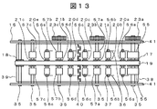
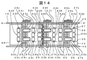
- FIGS. 13 and 14 show a configuration in which the toothed belt 19 of FIGS. 6 and 7 is changed from two to one. The same reference numerals as those in FIGS. 6 and 7 are not described.
- a banknote is clamped and conveyed only by one belt and a counter roller, a skew that rotates the posture of the banknote and a shift that moves sideways are generated, so that the banknote is clamped at two or more locations.
- the toothed belt 19 of FIG. 6 arranges the toothed belt 19 of FIG. 6 at the center of the conveyance path.
- the toothed pulleys 17, 21 a, 21 b, and 21 c are provided at the center of the rotating shaft 35, and the conveyance rollers 55, 57 a, 57 b, and 57 c are provided on both sides thereof.
- the toothed pressure pulleys 20a to 20e are provided at the innermost part of the rotary shaft 37, and the pressure rollers 56a to 56e are provided on both sides thereof.
- roller 14 has rollers 26a and 26b provided at both ends of the rotation shaft 35, and has conveyance rollers 62a and 62b at the center thereof. Further, the pressing rollers 33a to 33b are provided at both ends of the rotating shaft 37, and the conveying rollers 60a to 60d are provided at the center thereof.
- the banknote 2 is nipped and conveyed by the pressing rollers 60a to 60d and the rollers 62a and 62b facing the flat surface side of the toothed belt 19 disposed in the central portion of the conveying path.
- pressing rollers 33a to 33d arranged to face the conveying rollers 55, 57a, 57b and 57c driven and rotated by the toothed belt 19, and rollers 24a and 24b arranged to face the pressing rollers 56a to 56e,
- the bills 2 are sandwiched and conveyed by the flat belts 27a, 27b, 27c and the rollers 26a, 26b wound around the 24c.
- the effect of FIG. 2 and the toothed belt can be integrated, so that the transport mechanism can be downsized. Furthermore, it is effective for cost reduction.
- the rollers are arranged on both sides of the toothed belt 19, when the toothed belt 19 moves in the belt disengagement direction, there is an effect that it does not come off by contacting either or both of the rollers on both sides.
- FIGS. 15 and 16 show a configuration in which the toothed belt 19 shown in FIGS. 9 and 10 is changed from two to one. Therefore, this configuration is a configuration in which the gears 23b and 23c of the upper transport unit 15 and the gears 25a, 25b and 26c of the lower transport unit 16 fitted thereto are omitted in FIGS.
- roller 15 has the same configuration as that shown in FIG. 16 has a configuration in which rollers 61a, 61b, and 61c are provided at the center of the rollers 24a, 24b, and 24c in FIG.
- the flat surface side of the toothed belt 19 and the rollers 61a, 61b, 61c are brought into contact with each other to drive and rotate the rollers 24a, 24b, 24c. Then, the flat belts 27a, 27b and 27c wound around the rollers 24a, 24b and 24c are rotationally driven.
- the effect of FIG. 8 and the toothed belt can be integrated, so that the transport mechanism can be downsized. Furthermore, it is effective for cost reduction.
- the rollers are arranged on both sides of the toothed belt 19, when the toothed belt 19 moves in the belt disengagement direction, there is an effect that it does not come off by contacting either or both of the rollers on both sides.
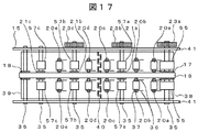
- FIGS. 17 and 18 show a configuration in which the toothed belt 19 of FIGS. 6 and 7 is changed from two to one.
- the same reference numerals as those in FIGS. 6 and 7 are not described.
- a banknote is clamped and conveyed only by one belt and a counter roller, a skew that rotates the posture of the banknote and a shift that moves sideways are generated, so that the banknote is clamped at two or more locations.
- the toothed pulleys 17, 21 a, 21 b, and 21 c are provided at the center of the rotating shaft 35, and the conveyance rollers 55, 57 a, 57 b, and 57 c are provided on both sides thereof. Further, the toothed pulley 18 is provided at the center of the rotating shaft 35. Further, the toothed pressure pulleys 20a to 20e are changed to pressure rollers 20a to 20e.
- rollers 26a and 26b at both ends of the rotation shaft 35, and conveyance rollers 62a and 62b at the center thereof.
- the banknote 2 is sandwiched and transported by the rollers 62a and 62b facing the plane side of the toothed belt 19 disposed at the center of the transport path. Further, pressing rollers 33a to 33d arranged to face the conveying rollers 55, 57a, 57b and 57c driven and rotated by the toothed belt 19, and rollers 24a and 24b arranged to face the pressing rollers 20a to 20e, The bills 2 are sandwiched and conveyed by the flat belts 27a, 27b, 27c and the rollers 26a, 26b wound around the 24c.
- the effect of FIG. 2 and the toothed belt can be integrated, so that the transport mechanism can be downsized. Furthermore, it is effective for cost reduction.
- the rollers are arranged on both sides of the toothed belt 19, when the toothed belt 19 moves in the belt disengagement direction, there is an effect that it does not come off by contacting either or both of the rollers on both sides.
- FIG. 19 and 20 show a configuration in which the toothed belt 19 shown in FIGS. 9 and 10 is changed from two to one. Therefore, this configuration is a configuration in which the gears 23b and 23c of the upper transport unit 15 and the gears 25a, 25b and 26c of the lower transport unit 16 fitted thereto are omitted in FIGS.
- 19 has the same configuration except that the gears 23b and 23c of FIG. 17 are omitted.
- 20 has a configuration in which rollers 61a, 61b, and 61c are provided at the center of the rollers 24a, 24b, and 24c in FIG.
- the flat surface side of the toothed belt 19 and the rollers 61a, 61b, 61c are brought into contact with each other to drive and rotate the rollers 24a, 24b, 24c. Then, the flat belts 27a, 27b and 27c wound around the rollers 24a, 24b and 24c are rotationally driven.
- the effect of FIG. 8 and the toothed belt can be integrated, so that the transport mechanism can be downsized. Furthermore, it is effective for cost reduction.
- the rollers are arranged on both sides of the toothed belt 19, when the toothed belt 19 moves in the belt disengagement direction, there is an effect that it does not come off by contacting either or both of the rollers on both sides.
- FIG. 21 Another embodiment of the paper sheet transport mechanism 9 using the toothed belt of the present invention will be described with reference to FIG.
- the flat belt of the branch conveyance path described above is changed to a toothed belt 27a (27b, 27c).
- the roller around which the toothed belt 27a (27b, 27c) is wound is changed to a toothed pulley 24a (24b, 24c), 28a (28b, 28c).
- the toothed belt 27a (27b, 27c) that rotates in contact with the toothed belt 19 does not cause a difference in conveyance speed from the toothed belt 19 even if there is a load fluctuation. Therefore, it has the effect of eliminating belt wear. Further, since there is no difference in the conveyance speed between the left and right toothed belts 27a (27b, 27c) of the rotary shaft 35, there is an effect of eliminating fluctuations in the banknote conveyance posture.
- a flange 242 is provided on the roller 24 a (24 b, 24 c) around which the flat belt 27 a (27 b, 27 c) on the branch conveyance path described above is wound.
- the flat belt 27a (27b, 27c) is wound around the roller portion 241 so as not to contact the toothed belt 19.
- the flanges 242 and the toothed belt 19 are brought into contact with each other to rotate the rollers 24a (24b, 24c), thereby rotating the flat belts 27a (27b, 27c).
- the flat belt 27a (27b, 27c) and the flanged roller 24a (24b, 24c) may be the toothed belt and the toothed pulley described in FIG.
- the flanged rollers 24a (24b, 24c) have a smaller coefficient of friction than the toothed belt 19, so that even if slippage occurs, the wear of the toothed belt 19 can be reduced.
- the toothed belt 19 having a large friction coefficient and the flat belts 27a (27b, 27c) are not in contact with each other, there is an effect that the flat belt is not worn.
- this invention is not limited to an above-described Example, Various modifications are included.
- the above-described embodiments have been described in detail for easy understanding of the present invention, and are not necessarily limited to those having all the configurations described.
- a part of the configuration of one embodiment can be replaced with the configuration of another embodiment, and the configuration of another embodiment can be added to the configuration of one embodiment.
- Each of the above-described configurations, functions, processing units, processing means, and the like may be realized by hardware by designing a part or all of them with, for example, an integrated circuit.
- Each of the above-described configurations, functions, and the like may be realized by software by interpreting and executing a program that realizes each function by the processor.
- Information such as programs, tables, and files for realizing each function can be stored in a recording device such as a memory, a hard disk, an SSD (Solid State Drive), or a recording medium such as an IC card, an SD card, or a DVD.
- the control lines and information lines indicate what is considered necessary for the explanation, and not all the control lines and information lines on the product are necessarily shown. Actually, it may be considered that almost all the components are connected to each other.
- SYMBOLS 1 Automatic teller machine, 2 ... Banknote, 3 ... Bill handling port, 4 ... Conveyance roller, 5 ... Conveyance path, 6 ... Discriminator, 7 ... Temporary stacker, 8 ... Gate, 9 ... Paper sheet conveyance mechanism, DESCRIPTION OF SYMBOLS 10 ... Bill collection box, 12a, 12b, 12c ... 12a-12e, 15 ... Upper conveyance part, 16 ... Lower conveyance part, 17 ... Pulse with a drive tooth, 18 ... Pulse with a driven tooth, 19 ... Toothed belt, 20a 20e ... toothed pressure pulley, 21a, 21b ...
Landscapes
- Physics & Mathematics (AREA)
- General Physics & Mathematics (AREA)
- Delivering By Means Of Belts And Rollers (AREA)
Abstract
現金自動預け払い機の搬送路の途中に分岐搬送路のある搬送機構に歯付きベルトを用い紙幣の搬送と動力伝達を兼用する。 駆動回転する歯付きプーリ17と従動回転する歯付きプーリ18とに掛け回された歯付きベルト19と、歯付きベルト19に対向して設けられた搬送ローラ33a~23d、26a、26bとで紙幣2を挟持して搬送する第一搬送路と、第一搬送路の途中から分岐する搬送ローラ24a~24cに掛け回された平ベルト27a~27cからなる第二搬送路と、第二搬送路への分岐ゲート22a、22b、22cとを備え、歯付きベルト19の駆動力を歯車23a~23cと歯車23a~23cを介して伝達し第二の搬送路の平ベルト27a~27cを回転するように構成する。
Description
本発明は、現金自動預け払い機に関し、例えば、搬送路の途中に分岐搬送路のある紙葉類搬送機構に歯付きベルトを用い紙幣の搬送と動力伝達を兼用する現金自動預け払い機に関する。
このような紙葉類搬送機構としては特許文献1(特開2002-230621号公報)がある。特許文献1には、歯付きベルトとローラで紙幣を挟持して搬送する紙葉類搬送機構が開示されている。
特許文献1に記載の紙葉類搬送機構は歯付きベルトとローラで紙幣のみを搬送する構成であって、歯付きベルトで他の搬送路に動力を伝達する記載はない。
本発明の目的は、第一の搬送路の途中から分岐する第二の搬送路のある紙葉類搬送機構に歯付きベルトを用い紙幣の搬送と動力伝達を兼用する小型化で高信頼の現金自動預け払い機を提供することにある。
上記課題を解決するために、例えば特許請求の範囲に記載の構成を採用する。本願は上記課題を解決する手段を複数含んでいるが、その一例を挙げるならば、駆動回転される駆動歯付きプーリと、従動回転する従動歯付きプーリと、前記歯付きプーリ間に掛け回された歯付きベルトと、前記歯付きベルトの歯に噛み合った歯付きプーリと、前記歯付きプーリに対向して設けられた搬送ローラとを備え、前記歯付きベルトの平面側と前記搬送ローラとで紙葉類を挟持して搬送する第一の搬送路を有する紙葉類搬送機構を設ける現金自動預け払い機において、前記第一の搬送路は上流側から順に前記歯付きベルトの歯に噛み合った第一の歯付きプーリと、前記第一の歯付きプーリの回転軸に設けた第一の歯車と、前記第一の歯付きプーリに対向して設けられた前記歯付きベルトを押圧する第一の搬送ローラと、前記歯付きベルトの歯に噛み合い前記歯付きベルトを押圧する第二の歯付きプーリと、前記第二の歯付きプーリに対向して設けられた第二の搬送ローラと、前記第二の搬送ローラの回転軸に設けた第二の歯車とを有し、前記第二の搬送ローラと他端の第三の搬送ローラに掛け回された平ベルトと、前記第三の搬送ローラに対向して設けられた前記平ベルトを押圧する押圧ローラとを有し、前記歯付きベルトの平面側と前記平ベルト間と、前記平ベルトと前記押圧ローラ間とで紙葉類を挟持して搬送する第二の搬送路と、前記第二の搬送ローラの下流側に設け前記第一の搬送路から前記第二の搬送路へ前記紙葉類を分岐するゲートとを備え、前記第一の搬送路の前記歯付きベルトで回転する前記第一の歯車と、前記第一の歯車と噛み合う前記第二の歯車を介して前記第二の搬送路を駆動回転する紙葉類搬送機構を設けることを特徴とする。
また、前記第一の搬送路は上流側から順に前記歯付きベルトの歯に噛み合った第一の歯付きプーリと、前記第一の歯付きプーリに対向して設けられた前記歯付きベルトを押圧する第一の搬送ローラと、前記歯付きベルトの歯に噛み合い前記歯付きベルトを押圧する第二の歯付きプーリと、前記第一の歯付きプーリに対向して設けられた第二の搬送ローラとを有し、前記第二の搬送ローラと他端の第三の搬送ローラに掛け回された平ベルトと、前記第三の搬送ローラに対向して設けられた前記平ベルトを押圧する押圧ローラとを有し、前記歯付きベルトの平面側と前記平ベルト間と、前記平ベルトと前記押圧ローラ間とで紙葉類を挟持して搬送する第二の搬送路と、前記第二の搬送ローラの下流側に設け前記第一の搬送路から前記第二の搬送路へ前記紙葉類を分岐するゲートとを備え、前記第一の搬送路の前記歯付きベルトの平面側に接触する前記第二の搬送路の前記平ベルトを駆動回転する紙葉類搬送機構を設けることを特徴とする。
また、前記第一の搬送路の幅方向中央部に1本の前記歯付きベルトと前記歯付きプーリを配置し、前記第一の搬送路は前記第一の歯付きプーリの回転軸に設けた第四の搬送ローラと前記第一の歯車と、前記第四の搬送ローラに対向して設けられた前記第一の搬送ローラと、前記第二の歯付きプーリの回転軸に設けた第五の搬送ローラと、前記第五の搬送ローラに対向して設けた前記第二の搬送ローラと、前記第二の搬送ローラの回転軸に設けた歯車とを有し、前記第二の搬送ローラと他端の第三の搬送ローラに掛け回された平ベルトと、前記第三の搬送ローラに対向して設けられた前記平ベルトを押圧する押圧ローラとを有し、前記第五の搬送ローラと前記平ベルト間と、前記平ベルトと前記押圧ローラ間とで紙葉類を挟持して搬送する第二の搬送路と、前記第二の搬送ローラの下流側に設け前記第一の搬送路から前記第二の搬送路へ前記紙葉類を分岐するゲートとを備え、前記第一の搬送路の前記歯付きベルトで回転する前記第一の歯車と、前記第一の歯車と噛み合う前記第二の歯車を介して前記第二の搬送路を駆動回転する紙葉類搬送機構を設けることを特徴とする。
また、前記第一の搬送路の幅方向中央部に1本の前記歯付きベルトと前記歯付きプーリを配置し、前記第一の搬送路は前記第一の歯付きプーリの回転軸に設けた第四の搬送ローラと、前記第四の搬送ローラに対向して設けられた第一の搬送ローラと、前記歯付きプーリの回転軸に設けた第五の搬送ローラと、前記第五の搬送ローラに対向して設けた前記第二の搬送ローラと、前記第二の搬送ローラの回転軸に前記歯付きプーリに対向して設け前記歯付きベルトの平面側と接触し回転する動力伝達ローラとを有し、前記第二の搬送ローラと他端の第三の搬送ローラに掛け回された平ベルトと、前記第三の搬送ローラに対向して設けられた前記平ベルトを押圧する押圧ローラとを有し、前記第五の搬送ローラと前記平ベルト間と、前記平ベルトと前記押圧ローラ間とで紙葉類を挟持して搬送する第二の搬送路と、前記第二の搬送ローラの下流側に設け前記第一の搬送路から前記第二の搬送路へ前記紙葉類を分岐するゲートとを備え、前記前記第一の搬送路の歯付きベルトで前記動力伝達ローラを回転させ、前記第二の搬送路を駆動回転する紙葉類搬送機構を設けることを特徴とする。
また、前記第一の歯付きプーリの外周と前記第二の歯付きプーリの外周の位置が段違いになるように前記前記第一の歯付きプーリと前記第二の歯付きプーリを配置し、前記歯付きベルトが波形にうねるようにする紙葉類搬送機構を設けることを特徴とする。
また、前記第二の搬送路の前記平ベルトを歯付きベルトに紙葉類搬送機構を設けることを特徴とする。
また、前記第二の搬送路の前記平ベルトを掛け回すローラの両側にフランジを設け、前記第一の搬送路の前記歯付きベルトの平面側と前記フランジとを接触させて前記ローラを回転させ、前記歯付きベルトの平面側と前記平ベルトを接触させないように紙葉類搬送機構を設けることを特徴とする。
また、前記第一の搬送路は歯付きベルトを含む上側搬送部と下側搬送部に分割し、前記第一の搬送路を解放できるように紙葉類搬送機構を設けることを特徴とする。
また、歯付きベルトと搬送ローラで紙葉類を挟持して搬送する第一搬送路と、第一搬送路の途中から分岐する平ベルトと搬送ローラで紙葉類を挟持して搬送する第二搬送路とを備え、第一搬送路の歯付きベルトで回転する歯車を介して第二搬送路の平ベルトを駆動回転する紙葉類搬送機構を設けることを特徴とする。
本発明によれば、第一の搬送路の途中から分岐する第二の搬送路のある紙葉類搬送機構に歯付きベルトを用い紙幣の搬送と動力伝達を兼用する小型化で高信頼の現金自動預け払い機を提供できる。
以下、本発明の詳細を図にしたがって説明する。なお、同一の符号を付された構成は、同一の機能を有するので、既に当該符号の説明されている場合それらの説明は省略することがある。
本発明の現金自動預け払い機の歯付きベルトを用いた紙葉類搬送機構の一実施例を、図1乃至図7を用いて説明する。
図1は現金自動預け払い機1の全体構成を示す側面図である。図2は本発明の歯付きベルトを用いた紙葉類搬送機構9の一部分を示す側面図である。図3は図2の歯付きベルトと歯付きプーリの構造を示す側面図である。図4は図2の搬送路が波形にうねる上側搬送部15と下側搬送部16を拡大した側面図である。図5は図2の搬送路が平面な上側搬送部15と下側搬送部16を拡大した側面図である。図6は図2の上側搬送部15をA方向から見た平面図である。図7は図2の下側搬送部16をB方向から見た平面図である。
図1の現金自動預け払い機1は、紙幣2の預け入れと払い出しのための紙幣取扱口3と、紙幣2を搬送する搬送ローラ4と、紙幣2の搬送路5(太線で示す)と、紙幣2の金種又は真偽を判定する鑑別器6と、紙幣2の収納時と払い出し時に一時的に紙幣2を蓄積しておく一時スタッカ7と、紙幣2の行き先を切替えるゲート8と、本発明の実施例の歯付きベルトを用いた紙葉類搬送機構9と、機械処理ができない紙幣2を収納するための紙幣回収箱10と、金種別に紙幣2を収納し払い出すための還流庫12a~12eと、で構成される。
次に、図1の現金自動預け払い機1の動作について説明する。紙幣預け入れ時には、紙幣取扱口3に供給された紙幣2は一枚ずつ分離され搬送路5に供給される。鑑別器6において紙幣2の金種と真券であるか偽券であるかの鑑別と、紙幣2が二枚以上重なっていないかを判別する。紙幣2が真券であり一枚及び折れ券の場合は一時スタッカ7に蓄積され取引金額を表示する。一方、供給した紙幣2に問題がある場合は供給した全ての紙幣2を紙幣取扱口3に戻す。取引が成立した場合は再び鑑別器6を通り紙幣2の金種と二枚以上重なっていないかをチェックする。そして、紙幣2は紙葉類搬送機構9で金種別に分岐されてそれぞれの還流庫12a~12eに収納される。紙幣払い出し時には還流庫12a~12eの紙幣2を一枚ずつ分離し紙葉類搬送機構9に供給する。鑑別器6において紙幣2が二枚以上重なっていないかを判別する。紙幣2が一枚の場合は紙幣取扱口3に払い出される。二枚以上重なっている場合及び折れ券の場合は一時スタッカ7に蓄積され、その後、紙幣回収箱10に収納される。
本発明の歯付きベルトを用いた紙葉類搬送機構9の一実施例を、図2乃至図7を用いて説明する。
図2は歯付きベルトを用いた紙葉類搬送機構9と、金種別の還流庫12a、12b、12cを示す。紙葉類搬送機構9は歯付きベルト19からなる上側搬送部15とローラからなる下側搬送部16で構成される。なお、下側搬送部16はジャム除去などの保守点検のために図7の筺体49のR-R‘を回転中心として下方向に回転し搬送路を解放することができる。
上側搬送部15は図6に示すように回転軸35を軸受けを介して筺体41に固定し所定の回転駆動装置により回転駆動される歯付きプーリ17と、回転軸35を軸受けを介して筺体41に固定し従動回転する歯付きプーリ18、21a、21b、21cと、下側搬送部16のローラ24a、24b、24c、26a、26bに歯付きベルト19を押圧するための歯付きベルト19方向に移動可能な歯付き押圧プーリ20a~20eと、歯付きプーリ17、18、21a、21b、21cと歯付き押圧プーリ20a~20eに掛け回された歯付きベルト19と、歯付きプーリ17、21a、21bの回転軸35に設けた歯車23a、23b、23cと、で構成される。なお、搬送路を波形にうねらせ歯付きベルトとローラとの押圧力の向上と紙幣2を変形させ剛性を向上させるようにする。そのために、歯付きプーリ21a、21bの外周を下側搬送部16のローラ24a、24b、24c、26a、26bの外周より下側に位置するように配置する。また、図6に示すように、歯付きプーリ17、18、21a、21b、21cと歯付き押圧プーリ20a~20eは搬送路の幅方向にそれぞれ2個設けられ、それぞれ搬送方向に直線上に配置され2本の歯付きベルト19が掛け回されている。
下側搬送部16は図7に示すように回転軸35を軸受けを介して筺体49に固定し歯付きベルト19により動力が伝達され回転駆動されるローラ24a、24b、24cと、回転軸35を軸受けを介して筺体49に固定し従動回転するローラ26a、26bと、上側搬送部15の歯付きプーリ17、21a、21a、21b、21cに対向して設けられ歯付きベルト19を押圧するための歯付きベルト19方向に移動可能な押圧ローラ33a~33dと、搬送されて来る紙幣2を還流庫12a、12b、12cに分岐するための回転軸35を軸受けを介して筺体49に固定した櫛歯状のゲート22a、22b、22cと、分岐した紙幣2を還流庫12a、12b、12cに搬送するためのローラ24a、24b、24cとローラ28a、28b、28cにそれぞれ掛け回された平ベルト27a、27b、27cと、ローラ28a、28b、28cに対向して設けられ平ベルト27a、27b、27cを押圧するための平ベルト方向に移動可能な押圧ローラ29a、29b、29cと、紙幣2を還流庫の紙幣入出口31a、31b、31cに案内するためのガイド30a、30b、30cと、ローラ24a、24b、24cの回転軸35に設けられ上側搬送部15の歯車23a、23b、23cと嵌合する歯車25a、25b、25cで構成される。このように、ローラ24a、24b、24cは上側搬送部15の歯付きベルト19の移動により歯付きプーリ21a、21b、21cを回転させると共に歯車23a、23b、23cと歯車25a、25b、25cを介して回転駆動される。また、ガイド30a、30b、30cは還流庫12a、12b、12cの方向に移動できる。還流庫12a、12b、12cを外部に取出すために移動する時には還流庫12a、12b、12cにぶつからない位置に退避する。なお、図7に示すように、ローラ24a、24b、24c、26a、26bと押圧ローラ33a~33dは搬送路の幅方向にそれぞれ2個設け上側搬送部15の歯付きプーリ17、21a、21b、21cと押圧歯付きプーリ20a~20eに対向して直線上に配置されている。また、ローラ24a、24b、24c、26a、26bのローラ外周はほぼ直線上に配置する。また、歯付きベルト19と分岐側の平ベルト27a、27b、27cの搬送速度が同じになる様に歯付きプーリ17の外周径とローラ24a、24b、24cの外周径をほぼ同じにすると共に、歯車23a、23b、23cと歯車25a、25b、25cのピッチ円(又は歯数)を同じにする。
還流庫12a、12b、12cは紙幣入出口31a、31b、31cと、紙幣2を一枚ずつ分離し繰出す又は紙幣2を収納するための紙幣分離集積機構32a、32b、32cと、紙幣2を集積する収納部から構成される。
次に図2の動作について説明する。以下、還流庫12a、12b、12cの紙幣2の収納と繰出し動作は同じなので還流庫12bについて説明する。収納時には、紙幣2は右方向から搬送されて来る。紙幣2は上側搬送部15の歯付きベルト19と対向して配置された下側搬送部16の平ベルト27a、27b、27cとローラ26a、26b及び押圧ローラ33a~33dで挟持され搬送される。ゲート22bで搬送路を塞ぐことにより紙幣2は還流庫12b方向に分岐される。そして、紙幣2は押圧ローラ29bに噛み込まれ平ベルト27bとで挟持されガイド30bに案内されて還流庫12bの入出口31bに搬送される。還流庫12bは紙幣分離集積機構32bにより取込み紙幣2を収納部に集積する。繰出し時には、還流庫12bの紙幣分離集積機構32bにより紙幣2を一枚ずつ分離し、収納時と同じルートを通り右方向に搬送される。なお、図4に示すようにゲート22bは紙幣2を通過させる場合はガイド45より下側に退避し、紙幣2を分岐させる場合はガイド38の上側に移動し搬送路を塞ぐように動作する。
従来、第一の搬送路と第一の搬送路の途中から分岐する第二の搬送路において、負荷変動などの外乱に対して搬送速度の変化がないように、第一の搬送路と第二の搬送路を回転駆動する別々の動力伝達機構が設けられていた。そこで、本発明の実施例では第一の搬送路は回転駆動される歯付きベルトの平面側とローラにより紙幣を挟持し搬送すると共に、歯付きベルトの歯付き側から第二の搬送路に回転動力を伝達するようにする。これにより、歯付きベルトのみで紙幣の搬送と駆動力の伝達ができるので搬送機構の小型化が可能となる。更には低コスト化に効果がある。また、歯付きベルトで動力を伝達するので滑りがないので第一の搬送路と第二の搬送路の搬送速度を同じにできる効果とエネルギーロスがないので省エネルギー化が可能となる。また、左右の歯付きベルト間で速度差がないので紙幣の姿勢が回転するスキュー、横に移動するシフトが生じないので搬送の高信頼性に効果がある。
図3に図2の歯付きベルト19と歯付きプーリ18及び歯付き押圧プーリ20bの一実施例を示す。図3の歯付きプーリ18はプーリ歯型を示す山部181と谷部182と、側面に設けたフランジ183と、回転軸35からなる。フランジ183の外周は紙幣2に接触しないように歯付きベルト19の外周より低くする。これにより、歯付きベルト19が蛇行してもフランジ183に歯付きベルト19の側面が接触し歯付きプーリ18から外れない効果がある。歯付きプーリ17も同様な構成である。また、符号191は歯付きベルトの平面側、符号192は歯付きベルトの歯付き側を示す。歯付き押圧プーリ20bはプーリ歯型を示す山部201と谷部202と、歯付きプーリ20bの回転軸37と、回転軸37の両端部を押圧するばね36と、プーリ取付け板204からなる。歯付きプーリ20bの回転軸37の両端はプーリ取付け板204の楕円形の軸受け205に挿入され回転軸37の両端部をばね36で押圧される。また、ばね36の一端はプーリ取付け板204に固定され、プーリ取付け板204はガイド38、39に固定される。これにより、ばね36で歯付きベルト19方向に歯付きプーリ20bを移動し押圧することができる。なお、フランジ付きの歯付きプーリ17、18により歯付きベルト19がプーリから外れ難くなるため、押圧歯付きプーリ20bはフランジを無くすことができる。他の歯付き押圧プーリ20a~20eも同様な構成である。また、歯付きプーリ21a、21bも歯付きプーリ部は同様な構成である。また、下側搬送部16の押圧ローラ33a~20dも歯付きプーリをローラにすれば同様な構成であって、プーリ取付け板204は図7に示すガイド45、46に固定される。
図4に図2の搬送路が波形にうねる上側搬送部15と下側搬送部16の一実施例の部分拡大図を示す。他の部分も同じ構成なので括弧で示す。図4では歯付きプーリ21a(21b)の外周を下側搬送部16のローラ26a(26b)とローラ24b(24c)の外周より下側に位置するように配置する。また、上側搬送部15の歯付きプーリ21a(17、21b、21c)と、歯付き押圧プーリ20b、20c(20a~20e)はガイド38(39)に貫通口を設け歯付きプーリが搬送路側に露出するように設けられている。また、図3に示すように歯付き押圧プーリ20b、20c(20a~20e)はガイド38(39)に設けられている。同様に、下側搬送部16のローラ24b、26a(24a、24c、26b)と、押圧ローラ33b(33a~33d)と、ゲート22b(22a、22c)はガイド45(46)に貫通口を設けローラの外周部が搬送路側に露出するように設けられている。なお、ゲート22b(22a、22c)は紙幣2を通過させる場合はガイド45(46)より下側に退避し、紙幣2を分岐させる場合はガイド38(39)の上側に移動し搬送路を塞ぐように動作する。また、押圧ローラ33a~33dはガイド45(46)に設けられている。なお、メンテナンス時に下側搬送部16を下側に回転移動し搬送路を解放しても、歯付き押圧プーリ20a~20eが移動し歯付きベルトの張力が弛まない。したがって、手などの外力が加わっても歯付きプーリから外れ難くなっている。
このように本発明の実施例によれば、搬送路を波形にうねらせ歯付きベルト19とローラ26a(26b)とローラ24b(24c)の平ベルト27b(27c)との押圧力の向上と紙幣2を変形させ剛性を向上させてジャムなどが生じない効果がある。
図5に図2の搬送路が平面の上側搬送部15と下側搬送部16の一実施例の部分拡大図を示す。図5は図4と同じ構成であり同じ符号の説明は省く。図5では歯付きプーリ21a(21b)の外周を下側搬送部16のローラ26a(26b)とローラ24b(24c)の外周と同じ位置に配置する。これにより、搬送路を平面にする。
このように本発明の実施例によれば、ガイド38、45の形状が平坦になり製作が容易になる効果がる。メンテナンス時に下側搬送部16を下側に回転移動し搬送路を解放しても、歯付きベルトの張力が弛まないので手などの外力が加わっても歯付きプーリから外れ難くなる効果がある。
図6に図2の上側搬送部15をA方向から見た平面図を示す。図2乃至図5と同じ符号は説明を省く。上側搬送部15は筺体41と、回転軸35を軸受けを介して筺体41に固定し所定の回転駆動装置により回転駆動される歯付きプーリ17と、回転軸35を軸受けを介して筺体41に固定し従動回転する歯付きプーリ18、21a、21b、21cと、下側搬送部16のローラ24a、24b、24c、26a、26bに歯付きベルト19を押圧するための歯付きベルト19方向に移動可能な歯付き押圧プーリ20a~20eと、歯付きプーリ17、18、21a、21b、21cと歯付き押圧プーリ20a~20eに掛け回された歯付きベルト19と、歯付きプーリ17、21a、21bの回転軸35に設けた歯車23a、23b、23cと、ガイド38、39で構成される。また、歯付き押圧プーリ20a~20eは、図3に示すようにばね36の一端がプーリ取付け板204に固定され、プーリ取付け板204はガイド38、39に固定される。また、ガイド38、39は端部40で分割されている。端部40は互いに櫛歯が咬み合った形状をしており紙幣2が引っ掛らないようになっている。
図7に図2の下側搬送部16をB方向から見た平面図を示す。図2乃至図5と同じ符号は説明を省く。上側搬送部16は筺体49と、回転軸35を軸受けを介して筺体49に固定し歯付きベルト19により動力が伝達され回転駆動されるローラ24a、24b、24cと、回転軸35を軸受けを介して筺体49に固定し従動回転するローラ26a、26bと、上側搬送部15の歯付きプーリ17、21a、21a、21b、21cに対向して設けられ歯付きベルト19を押圧するための歯付きベルト19方向に移動可能な押圧ローラ33a~33dと、搬送されて来る紙幣2を還流庫12a、12b、12cに分岐するための回転軸35を軸受けを介して筺体49に固定したゲート22a、22b、22cと、分岐した紙幣2を還流庫12a、12b、12cに搬送するためのローラ24a、24b、24cにそれぞれ掛け回された平ベルト27a、27b、27cと、ローラ24a、24b、24cの回転軸35に設けられ上側搬送部15の歯車23a、23b、23cと嵌合する歯車25a、25b、25cで構成される。また、押圧ローラ33a~33eは、図3に示すようにばね36の一端がプーリ取付け板204に固定され、プーリ取付け板204はガイド45、46に固定される。また、ガイド45、46は端部47で分割されている。端部47は互いに櫛歯が咬み合った形状をしており紙幣2が引っ掛らないようになっている。
本発明の歯付きベルトを用いた紙葉類搬送機構9の他の一実施例を、図8、図9、図10を用いて説明する。図8、図9、図10は図2、図6、図7に示す上側搬送部15の歯車23b、23cと、これに嵌合する下側搬送部16の歯車25a、25b、26cを省いた構成である。なお、図2、図6、図7と同じ符号は説明を省く。図8、図9、図10は、上側搬送部15の歯付きベルト19から下側搬送部16への平ベルト24a、24b、24cへの動力伝達を歯付きベルト19と平ベルト24a、24b、24cの摩擦力で行う構成である。また、図4のうねり搬送路を用いれば歯付きベルト19をうねらせることにより歯付きベルト19と平ベルト24a、24b、24cの押付力を大きくすることで摩擦力が向上し滑りの発生をなくすことができる。また、図5の平面搬送路を用いれば歯付き押圧プーリ20a、20c、20eの押付力を大きくすることで摩擦力が向上し滑りの発生をなくすことができる。
このように本発明の実施例によれば、第一の搬送路は回転駆動される歯付きベルトの平面側とローラにより紙幣を挟持し搬送すると共に、歯付きベルトの平面側と第二の搬送路の搬送ベルトを接触させて回転動力を伝達するようにする。これにより、歯付きベルトのみで紙幣の搬送と駆動力の伝達ができるので搬送機構の小型化が可能となる。更には低コスト化に効果がある。また、歯付きベルトで動力を伝達するので滑りがないので第一の搬送路と第二の搬送路の搬送速度を同じにできる効果とエネルギーロスがないので省エネルギー化が可能となる。また、左右の歯付きベルト間で速度差がないので紙幣の姿勢が回転するスキュー、横に移動するシフトが生じないので搬送の高信頼性に効果がある。
本発明の歯付きベルトを用いた紙葉類搬送機構9の他の一実施例を、図11を用いて説明する。図11は図6に示す上側搬送部15の歯付き押圧ローラ20a~20eを省いた構成である。なお、図6と同じ符号は説明を省く。また、図4に示すうねり搬送路を用いると歯付きベルト19をうねらせることにより歯付きベルト19と下搬送部16の平ベルト24a、24b、24cとローラ26a、26bとの押付力を大きくでき滑りの発生をなくすことができる。したがって、歯付きベルト19を押圧する歯付き押圧ローラ20a~20eを省くことができる。
このように本発明の実施例によれば、図2の効果と、歯付き押圧ローラ20a~20eを省くことができるので搬送機構の小型化と低コスト化に効果がある。
本発明の歯付きベルトを用いた紙葉類搬送機構9の他の一実施例を、図12を用いて説明する。図12は図9に示す上側搬送部15の歯付き押圧ローラ20a~20eを省いた構成である。なお、図9と同じ符号は説明を省く。また、図4のうねり搬送路を用いると歯付きベルト19をうねらせることにより歯付きベルト19と下搬送部16の平ベルト24a、24b、24cとローラ26a、26bとの押付力を大きくでき滑りの発生をなくすことができる。したがって、歯付きベルト19を押圧する歯付き押圧ローラ20a~20eを省くことができる。
このように本発明の実施例によれば、図8を用いて述べた効果と、歯付き押圧ローラ20a~20eを省くことができるので搬送機構の更なる小型化が可能となる。更には低コスト化に効果がある。
本発明の歯付きベルトを用いた紙葉類搬送機構9の他の一実施例を、図13、図14を用いて説明する。図13、図14は図6、図7の歯付きベルト19を二本から一本にした構成である。なお、図6、図7と同じ符号は説明を省く。なお、1本ベルトと対向ローラのみで紙幣を挟持して搬送した場合、紙幣の姿勢が回転するスキュー、横に移動するシフトが生じるため2個所以上で挟持する構成にする。
図13に示す上側搬送部15は、図6の歯付きベルト19を搬送路の中央部に配置する。そして、歯付きプーリ17、21a、21b、21cを回転軸35の中央部に設け、その両側に搬送ローラ55、57a、57b、57cを設ける。また、歯付き押圧プーリ20a~20eを回転軸37の中奥部に設け、その両側に押圧ローラ56a~56eを設ける。
図14に示す下側搬送部16は、ローラ26a、26bを回転軸35の両端部に設け、その中央部に搬送ローラ62a、62bを設ける。また、押圧ローラ33a~33bを回転軸37の両端部に設け、その中央部に搬送ローラ60a~60dを設ける。
これにより、搬送路の中央部に配置された歯付きベルト19の平面側と対向する押圧ローラ60a~60d及びローラ62a、62bで紙幣2を挟持して搬送する。また、歯付きベルト19で駆動回転する搬送ローラ55、57a、57b、57cに対向して配置された押圧ローラ33a~33dと、押圧ローラ56a~56eに対向して配置されたローラ24a、24b、24cに掛け回された平ベルト27a、27b、27cとローラ26a、26bとで紙幣2を挟持して搬送する。
このように本発明の実施例によれば、図2の効果と、歯付きベルトを一本にできるので搬送機構の小型化が可能となる。更には低コスト化に効果がある。また、歯付きベルト19の両側にローラが配置されているので歯付きベルト19がベルト外れ方向に移動した場合、両側のローラのいずれか又は両方に接触して外れない効果がある。
本発明の歯付きベルトを用いた紙葉類搬送機構9の他の一実施例を、図15、図16を用いて説明する。図15、図16は図9、図10の歯付きベルト19を二本から一本にした構成である。したがって、この構成は図13、図14の上側搬送部15の歯車23b、23cと、これに嵌合する下側搬送部16の歯車25a、25b、26cを省いた構成である。
図15に示す上側搬送部15は図13と同じ構成である。図16に示す下側搬送部16は図14のローラ24a、24b、24cの中央部にローラ61a、61b、61cを設けた構成である。
これにより、歯付きベルト19の平面側と、ローラ61a、61b、61cを接触させローラ24a、24b、24cを駆動回転させる。そして、ローラ24a、24b、24cに掛け回された平ベルト27a、27b、27cを回転駆動する。
このように本発明の実施例によれば、図8の効果と、歯付きベルトを一本にできるので搬送機構の小型化が可能となる。更には低コスト化に効果がある。また、歯付きベルト19の両側にローラが配置されているので歯付きベルト19がベルト外れ方向に移動した場合、両側のローラのいずれか又は両方に接触して外れない効果がある。
本発明の歯付きベルトを用いた紙葉類搬送機構9の他の一実施例を、図17、図18を用いて説明する。図17、図18は図6、図7の歯付きベルト19を二本から一本にした構成である。なお、図6、図7と同じ符号は説明を省く。なお、1本ベルトと対向ローラのみで紙幣を挟持して搬送した場合、紙幣の姿勢が回転するスキュー、横に移動するシフトが生じるため2個所以上で挟持する構成にする。
図17に示す上側搬送部15は、図6の歯付きベルト19を搬送路の中央部に配置する。そして、歯付きプーリ17、21a、21b、21cを回転軸35の中央部に設け、その両側に搬送ローラ55、57a、57b、57cを設ける。また、歯付きプーリ18を回転軸35の中央部に設ける。また、歯付き押圧プーリ20a~20eを押圧ローラ20a~20eに変更する。
図18に示す下側搬送部16は、ローラ26a、26bを回転軸35の両端部に設け、その中央部に搬送ローラ62a、62bを設ける。
これにより、搬送路の中央部に配置された歯付きベルト19の平面側と対向するローラ62a、62bで紙幣2を挟持して搬送する。また、歯付きベルト19で駆動回転する搬送ローラ55、57a、57b、57cに対向して配置された押圧ローラ33a~33dと、押圧ローラ20a~20eに対向して配置されたローラ24a、24b、24cに掛け回された平ベルト27a、27b、27cとローラ26a、26bとで紙幣2を挟持して搬送する。
このように本発明の実施例によれば、図2の効果と、歯付きベルトを一本にできるので搬送機構の小型化が可能となる。更には低コスト化に効果がある。また、歯付きベルト19の両側にローラが配置されているので歯付きベルト19がベルト外れ方向に移動した場合、両側のローラのいずれか又は両方に接触して外れない効果がある。
本発明の歯付きベルトを用いた紙葉類搬送機構9の他の一実施例を、図19、図20を用いて説明する。図19、図20は図9、図10の歯付きベルト19を二本から一本にした構成である。したがって、この構成は図17、図18の上側搬送部15の歯車23b、23cと、これに嵌合する下側搬送部16の歯車25a、25b、26cを省いた構成である。
図19に示す上側搬送部15は図17の歯車23b、23cを省いた以外同じ構成である。図20に示す下側搬送部16は図18のローラ24a、24b、24cの中央部にローラ61a、61b、61cを設けた構成である。
これにより、歯付きベルト19の平面側と、ローラ61a、61b、61cを接触させローラ24a、24b、24cを駆動回転させる。そして、ローラ24a、24b、24cに掛け回された平ベルト27a、27b、27cを回転駆動する。
このように本発明の実施例によれば、図8の効果と、歯付きベルトを一本にできるので搬送機構の小型化が可能となる。更には低コスト化に効果がある。また、歯付きベルト19の両側にローラが配置されているので歯付きベルト19がベルト外れ方向に移動した場合、両側のローラのいずれか又は両方に接触して外れない効果がある。
本発明の歯付きベルトを用いた紙葉類搬送機構9の他の一実施例を、図21を用いて説明する。図21は上記で説明した分岐搬送路の平ベルトを歯付きベルト27a(27b、27c)に変更する。また、歯付きベルト27a(27b、27c)を掛け回すローラを歯付きプーリ24a(24b、24c)、28a(28b、28c)に変更する。
このように本発明の実施例によれば、歯付きベルト19と接触して回転する歯付きベルト27a(27b、27c)は負荷変動があっても歯付きベルト19との搬送速度差が生じないのでベルトの摩耗をなくす効果がある。また、回転軸35の左右の歯付きベルト27a(27b、27c)の搬送速度差がないので紙幣の搬送姿勢変動をなくす効果がある。
本発明の歯付きベルトを用いた紙葉類搬送機構9の他の一実施例を、図22を用いて説明する。図22は上記で説明した分岐搬送路の平ベルト27a(27b、27c)を掛け回すローラ24a(24b、24c)にフランジ242を設ける。平ベルト27a(27b、27c)は歯付きベルト19と接触しないようにローラ部241に掛け回す。フランジ242と歯付きベルト19を接触させてローラ24a(24b、24c)を回転させて平ベルト27a(27b、27c)を回転させる。なお、平ベルト27a(27b、27c)とフランジ付きローラ24a(24b、24c)を図21で説明した歯付きベルトと歯付きプーリにすることもできる。
このように本発明の実施例によれば、フランジ付きローラ24a(24b、24c)は歯付きベルト19より摩擦係数が小さいのですべりが発生しても歯付きベルト19の摩耗を少なくできる効果がある。また、摩擦係数の大きい歯付きベルト19と平ベルト27a(27b、27c)は接触しないので平ベルトが摩耗しない効果がある。
なお、本発明は上記した実施例に限定されるものではなく、様々な変形例が含まれる。
例えば、上記した実施例は本発明を分かりやすく説明するために詳細に説明したものであり、必ずしも説明した全ての構成を備えるものに限定されるものではない。また、ある実施例の構成の一部を他の実施例の構成に置き換えることが可能であり、また、ある実施例の構成に他の実施例の構成を加えることも可能である。また、各実施例の構成の一部について、他の構成の追加・削除・置換をすることが可能である。
また、上記の各構成、機能、処理部、処理手段等は、それらの一部又は全部を、例えば集積回路で設計する等によりハードウェアで実現してもよい。また、上記の各構成、機能等は、プロセッサがそれぞれの機能を実現するプログラムを解釈し、実行することによりソフトウェアで実現してもよい。各機能を実現するプログラム、テーブル、ファイル等の情報は、メモリや、ハードディスク、SSD(Solid State Drive)等の記録装置、または、ICカード、SDカード、DVD等の記録媒体に置くことができる。
また、制御線や情報線は説明上必要と考えられるものを示しており、製品上必ずしも全ての制御線や情報線を示しているとは限らない。実際には殆ど全ての構成が相互に接続されていると考えてもよい。
例えば、上記した実施例は本発明を分かりやすく説明するために詳細に説明したものであり、必ずしも説明した全ての構成を備えるものに限定されるものではない。また、ある実施例の構成の一部を他の実施例の構成に置き換えることが可能であり、また、ある実施例の構成に他の実施例の構成を加えることも可能である。また、各実施例の構成の一部について、他の構成の追加・削除・置換をすることが可能である。
また、上記の各構成、機能、処理部、処理手段等は、それらの一部又は全部を、例えば集積回路で設計する等によりハードウェアで実現してもよい。また、上記の各構成、機能等は、プロセッサがそれぞれの機能を実現するプログラムを解釈し、実行することによりソフトウェアで実現してもよい。各機能を実現するプログラム、テーブル、ファイル等の情報は、メモリや、ハードディスク、SSD(Solid State Drive)等の記録装置、または、ICカード、SDカード、DVD等の記録媒体に置くことができる。
また、制御線や情報線は説明上必要と考えられるものを示しており、製品上必ずしも全ての制御線や情報線を示しているとは限らない。実際には殆ど全ての構成が相互に接続されていると考えてもよい。
1…現金自動預け払い機、2…紙幣、3…紙幣取扱口、4…搬送ローラ、5…搬送路、6…鑑別器、7…一時スタッカ、8…ゲート、9…紙葉類搬送機構、10…紙幣回収箱、12a、12b、12c…12a~12e、15…上側搬送部、16…下側搬送部、17…駆動歯付きプーリ、18…従動歯付きプーリ、19…歯付きベルト、20a~20e…歯付き押圧プーリ、21a、21b…歯付き押圧プーリ、22a、22b、22c…ゲート、23a、23b、23c…歯車、24a、24b、24c…ローラ、25a、25b、25c…歯車、26a、26b…ローラ、27a、27b、27c…平ベルト、28a、28b、28c…ローラ、29a、29b、29c…押圧ローラ、30a、30b、30c…ガイド、31a、31b、31c…入出口、32a、32b、32c…紙幣分離集積機構
Claims (9)
- 駆動回転される駆動歯付きプーリと、従動回転する従動歯付きプーリと、前記歯付きプーリ間に掛け回された歯付きベルトと、前記歯付きベルトの歯に噛み合った歯付きプーリと、前記歯付きプーリに対向して設けられた搬送ローラとを備え、前記歯付きベルトの平面側と前記搬送ローラとで紙葉類を挟持して搬送する第一の搬送路を有する紙葉類搬送機構を設ける現金自動預け払い機において、
前記第一の搬送路は上流側から順に前記歯付きベルトの歯に噛み合った第一の歯付きプーリと、前記第一の歯付きプーリの回転軸に設けた第一の歯車と、前記第一の歯付きプーリに対向して設けられた前記歯付きベルトを押圧する第一の搬送ローラと、前記歯付きベルトの歯に噛み合い前記歯付きベルトを押圧する第二の歯付きプーリと、前記第二の歯付きプーリに対向して設けられた第二の搬送ローラと、前記第二の搬送ローラの回転軸に設けた第二の歯車とを有し、前記第二の搬送ローラと他端の第三の搬送ローラに掛け回された平ベルトと、前記第三の搬送ローラに対向して設けられた前記平ベルトを押圧する押圧ローラとを有し、前記歯付きベルトの平面側と前記平ベルト間と、前記平ベルトと前記押圧ローラ間とで紙葉類を挟持して搬送する第二の搬送路と、前記第二の搬送ローラの下流側に設け前記第一の搬送路から前記第二の搬送路へ前記紙葉類を分岐するゲートとを備え、前記第一の搬送路の前記歯付きベルトで回転する前記第一の歯車と、前記第一の歯車と噛み合う前記第二の歯車を介して前記第二の搬送路を駆動回転する紙葉類搬送機構を設けることを特徴とする現金自動預け払い機。 - 請求項1において、
前記第一の搬送路は上流側から順に前記歯付きベルトの歯に噛み合った第一の歯付きプーリと、前記第一の歯付きプーリに対向して設けられた前記歯付きベルトを押圧する第一の搬送ローラと、前記歯付きベルトの歯に噛み合い前記歯付きベルトを押圧する第二の歯付きプーリと、前記第一の歯付きプーリに対向して設けられた第二の搬送ローラとを有し、前記第二の搬送ローラと他端の第三の搬送ローラに掛け回された平ベルトと、前記第三の搬送ローラに対向して設けられた前記平ベルトを押圧する押圧ローラとを有し、前記歯付きベルトの平面側と前記平ベルト間と、前記平ベルトと前記押圧ローラ間とで紙葉類を挟持して搬送する第二の搬送路と、前記第二の搬送ローラの下流側に設け前記第一の搬送路から前記第二の搬送路へ前記紙葉類を分岐するゲートとを備え、前記第一の搬送路の前記歯付きベルトの平面側に接触する前記第二の搬送路の前記平ベルトを駆動回転する紙葉類搬送機構を設けることを特徴とする現金自動預け払い機。 - 請求項1において、
前記第一の搬送路の幅方向中央部に1本の前記歯付きベルトと前記歯付きプーリを配置し、前記第一の搬送路は前記第一の歯付きプーリの回転軸に設けた第四の搬送ローラと前記第一の歯車と、前記第四の搬送ローラに対向して設けられた前記第一の搬送ローラと、前記第二の歯付きプーリの回転軸に設けた第五の搬送ローラと、前記第五の搬送ローラに対向して設けた前記第二の搬送ローラと、前記第二の搬送ローラの回転軸に設けた歯車とを有し、前記第二の搬送ローラと他端の第三の搬送ローラに掛け回された平ベルトと、前記第三の搬送ローラに対向して設けられた前記平ベルトを押圧する押圧ローラとを有し、前記第五の搬送ローラと前記平ベルト間と、前記平ベルトと前記押圧ローラ間とで紙葉類を挟持して搬送する第二の搬送路と、前記第二の搬送ローラの下流側に設け前記第一の搬送路から前記第二の搬送路へ前記紙葉類を分岐するゲートとを備え、前記第一の搬送路の前記歯付きベルトで回転する前記第一の歯車と、前記第一の歯車と噛み合う前記第二の歯車を介して前記第二の搬送路を駆動回転する紙葉類搬送機構を設けることを特徴とする現金自動預け払い機。 - 請求項1において、
前記第一の搬送路の幅方向中央部に1本の前記歯付きベルトと前記歯付きプーリを配置し、前記第一の搬送路は前記第一の歯付きプーリの回転軸に設けた第四の搬送ローラと、前記第四の搬送ローラに対向して設けられた第一の搬送ローラと、前記歯付きプーリの回転軸に設けた第五の搬送ローラと、前記第五の搬送ローラに対向して設けた前記第二の搬送ローラと、前記第二の搬送ローラの回転軸に前記歯付きプーリに対向して設け前記歯付きベルトの平面側と接触し回転する動力伝達ローラとを有し、前記第二の搬送ローラと他端の第三の搬送ローラに掛け回された平ベルトと、前記第三の搬送ローラに対向して設けられた前記平ベルトを押圧する押圧ローラとを有し、前記第五の搬送ローラと前記平ベルト間と、前記平ベルトと前記押圧ローラ間とで紙葉類を挟持して搬送する第二の搬送路と、前記第二の搬送ローラの下流側に設け前記第一の搬送路から前記第二の搬送路へ前記紙葉類を分岐するゲートとを備え、前記前記第一の搬送路の歯付きベルトで前記動力伝達ローラを回転させ、前記第二の搬送路を駆動回転する紙葉類搬送機構を設けることを特徴とする現金自動預け払い機。 - 請求項1において、
前記第一の歯付きプーリの外周と前記第二の歯付きプーリの外周の位置が段違いになるように前記前記第一の歯付きプーリと前記第二の歯付きプーリを配置し、前記歯付きベルトが波形にうねるようにする紙葉類搬送機構を設けることを特徴とする現金自動預け払い機。 - 請求項1において、
前記第二の搬送路の前記平ベルトを歯付きベルトに紙葉類搬送機構を設けることを特徴とする現金自動預け払い機。 - 請求項1かにおいて、
前記第二の搬送路の前記平ベルトを掛け回すローラの両側にフランジを設け、前記第一の搬送路の前記歯付きベルトの平面側と前記フランジとを接触させて前記ローラを回転させ、前記歯付きベルトの平面側と前記平ベルトを接触させないように紙葉類搬送機構を設けることを特徴とする現金自動預け払い機。 - 請求項1において、
前記第一の搬送路は歯付きベルトを含む上側搬送部と下側搬送部に分割し、前記第一の搬送路を解放できるように紙葉類搬送機構を設けることを特徴とする現金自動預け払い機。 - 歯付きベルトと搬送ローラで紙葉類を挟持して搬送する第一搬送路と、第一搬送路の途中から分岐する平ベルトと搬送ローラで紙葉類を挟持して搬送する第二搬送路とを備え、第一搬送路の歯付きベルトで回転する歯車を介して第二搬送路の平ベルトを駆動回転する紙葉類搬送機構を設けることを特徴とする現金自動預け払い機。
Applications Claiming Priority (2)
| Application Number | Priority Date | Filing Date | Title |
|---|---|---|---|
| JP2012274192A JP5899107B2 (ja) | 2012-12-17 | 2012-12-17 | 現金自動預け払い機 |
| JP2012-274192 | 2012-12-17 |
Publications (1)
| Publication Number | Publication Date |
|---|---|
| WO2014097856A1 true WO2014097856A1 (ja) | 2014-06-26 |
Family
ID=50902990
Family Applications (1)
| Application Number | Title | Priority Date | Filing Date |
|---|---|---|---|
| PCT/JP2013/082122 Ceased WO2014097856A1 (ja) | 2012-12-17 | 2013-11-29 | 現金自動預け払い機 |
Country Status (3)
| Country | Link |
|---|---|
| JP (1) | JP5899107B2 (ja) |
| CN (1) | CN103863878B (ja) |
| WO (1) | WO2014097856A1 (ja) |
Families Citing this family (8)
| Publication number | Priority date | Publication date | Assignee | Title |
|---|---|---|---|---|
| CN104355191B (zh) * | 2014-09-04 | 2016-12-07 | 广州广电运通金融电子股份有限公司 | 递钞式纸币输送装置 |
| JP6490482B2 (ja) * | 2015-04-09 | 2019-03-27 | 日立オムロンターミナルソリューションズ株式会社 | 紙幣取引装置、動力伝達機構 |
| CN105184960A (zh) * | 2015-10-08 | 2015-12-23 | 昆山古鳌电子机械有限公司 | 自动存取款机 |
| WO2018139123A1 (ja) | 2017-01-25 | 2018-08-02 | 三菱電機株式会社 | 筐体及び磁気センサ装置 |
| CN108492449A (zh) * | 2018-04-25 | 2018-09-04 | 中电金融设备系统(深圳)有限公司 | 闸门装置和自动存取款机 |
| CN109816850B (zh) * | 2018-12-17 | 2022-12-06 | 恒银金融科技股份有限公司 | 一种纸币输送通道搭接模块的动力轮受力分配方法 |
| JP7242403B2 (ja) * | 2019-04-24 | 2023-03-20 | 日立チャネルソリューションズ株式会社 | 紙葉類搬送機構 |
| CN113706766B (zh) * | 2021-10-27 | 2022-03-08 | 恒银金融科技股份有限公司 | 一种机芯大角度回转通道 |
Citations (2)
| Publication number | Priority date | Publication date | Assignee | Title |
|---|---|---|---|---|
| JPH02267684A (ja) * | 1989-02-28 | 1990-11-01 | De La Rue Co Plc:The | 物品取扱い装置 |
| JP2008125697A (ja) * | 2006-11-20 | 2008-06-05 | Oizumi Corp | 紙幣処理装置 |
Family Cites Families (7)
| Publication number | Priority date | Publication date | Assignee | Title |
|---|---|---|---|---|
| JPH08235410A (ja) * | 1995-02-27 | 1996-09-13 | Hitachi Ltd | 紙葉類取扱装置 |
| JP3055950B2 (ja) * | 1995-11-21 | 2000-06-26 | 富士通株式会社 | 紙葉類処理装置 |
| WO1999050797A1 (fr) * | 1998-03-27 | 1999-10-07 | Omron Corporation | Capteur d'identification de la qualite du papier et dispositif de tri du papier defectueux |
| JP4130887B2 (ja) * | 2002-10-03 | 2008-08-06 | 日立オムロンターミナルソリューションズ株式会社 | 紙幣収納放出装置及び紙幣搬送装置 |
| JP4843702B2 (ja) * | 2009-09-10 | 2011-12-21 | 東芝テック株式会社 | 媒体処理装置 |
| JP5647798B2 (ja) * | 2010-02-26 | 2015-01-07 | 日立オムロンターミナルソリューションズ株式会社 | 紙葉取扱装置 |
| CN202219652U (zh) * | 2011-08-18 | 2012-05-16 | 山东新北洋信息技术股份有限公司 | 出纸机构、打印装置和终端设备 |
-
2012
- 2012-12-17 JP JP2012274192A patent/JP5899107B2/ja not_active Expired - Fee Related
-
2013
- 2013-11-29 WO PCT/JP2013/082122 patent/WO2014097856A1/ja not_active Ceased
- 2013-12-04 CN CN201310643810.4A patent/CN103863878B/zh active Active
Patent Citations (2)
| Publication number | Priority date | Publication date | Assignee | Title |
|---|---|---|---|---|
| JPH02267684A (ja) * | 1989-02-28 | 1990-11-01 | De La Rue Co Plc:The | 物品取扱い装置 |
| JP2008125697A (ja) * | 2006-11-20 | 2008-06-05 | Oizumi Corp | 紙幣処理装置 |
Also Published As
| Publication number | Publication date |
|---|---|
| JP5899107B2 (ja) | 2016-04-06 |
| CN103863878A (zh) | 2014-06-18 |
| JP2014119935A (ja) | 2014-06-30 |
| CN103863878B (zh) | 2016-11-16 |
Similar Documents
| Publication | Publication Date | Title |
|---|---|---|
| JP5899107B2 (ja) | 現金自動預け払い機 | |
| JP5267345B2 (ja) | 媒体処理装置 | |
| US8297427B2 (en) | Banknote handling apparatus | |
| JP5463748B2 (ja) | 媒体処理装置 | |
| KR101362607B1 (ko) | 매체 보관함, 매체처리장치 및 금융 기기 | |
| US9738475B2 (en) | Medium conveying device and medium transaction device | |
| JP5187167B2 (ja) | 媒体処理装置 | |
| US8448780B2 (en) | Sheet bundle conveying apparatus and paper sheet handling apparatus | |
| KR20180051722A (ko) | 지폐 반송경로 절환장치 및 이를 구비한 금융자동화기기 | |
| KR101459825B1 (ko) | 매체이송장치 및 이를 이용한 금융기기 | |
| WO2015136780A1 (ja) | 媒体集積繰出装置及び紙幣取引装置 | |
| JP5287277B2 (ja) | 紙幣処理装置及び金銭処理機 | |
| KR20100007128U (ko) | 금융자동화기기의 반송로 구조 | |
| JP5426249B2 (ja) | 紙幣処理装置及び金銭処理機 | |
| JP2012174047A (ja) | 紙幣処理装置 | |
| JP5582223B2 (ja) | 媒体処理装置 | |
| JP2004292083A (ja) | 紙葉類搬送機構 | |
| CN205015968U (zh) | 自动存取款机 | |
| JP2010159110A (ja) | 紙幣処理装置及び金銭処理機 | |
| WO2018211939A1 (ja) | 紙葉類収納装置、紙葉類収納方法、及び、紙葉類処理装置 | |
| WO2025108345A1 (zh) | 纸币集积装置、现金循环处理设备和纸币集积控制方法 | |
| JP2017151558A (ja) | 硬貨処理装置 | |
| WO2025177666A1 (ja) | 媒体識別装置及び媒体処理装置 | |
| JP2020179954A (ja) | 紙葉類搬送機構 | |
| JP2018106244A (ja) | 紙幣処理装置 |
Legal Events
| Date | Code | Title | Description |
|---|---|---|---|
| 121 | Ep: the epo has been informed by wipo that ep was designated in this application |
Ref document number: 13866162 Country of ref document: EP Kind code of ref document: A1 |
|
| NENP | Non-entry into the national phase |
Ref country code: DE |
|
| 122 | Ep: pct application non-entry in european phase |
Ref document number: 13866162 Country of ref document: EP Kind code of ref document: A1 |