WO2014097543A1 - 成膜装置および成膜方法 - Google Patents
成膜装置および成膜方法 Download PDFInfo
- Publication number
- WO2014097543A1 WO2014097543A1 PCT/JP2013/006891 JP2013006891W WO2014097543A1 WO 2014097543 A1 WO2014097543 A1 WO 2014097543A1 JP 2013006891 W JP2013006891 W JP 2013006891W WO 2014097543 A1 WO2014097543 A1 WO 2014097543A1
- Authority
- WO
- WIPO (PCT)
- Prior art keywords
- spray
- spray nozzle
- raw material
- material liquid
- sprayed
- Prior art date
- Legal status (The legal status is an assumption and is not a legal conclusion. Google has not performed a legal analysis and makes no representation as to the accuracy of the status listed.)
- Ceased
Links
Images








Classifications
-
- B—PERFORMING OPERATIONS; TRANSPORTING
- B05—SPRAYING OR ATOMISING IN GENERAL; APPLYING FLUENT MATERIALS TO SURFACES, IN GENERAL
- B05B—SPRAYING APPARATUS; ATOMISING APPARATUS; NOZZLES
- B05B5/00—Electrostatic spraying apparatus; Spraying apparatus with means for charging the spray electrically; Apparatus for spraying liquids or other fluent materials by other electric means
- B05B5/025—Discharge apparatus, e.g. electrostatic spray guns
-
- B—PERFORMING OPERATIONS; TRANSPORTING
- B05—SPRAYING OR ATOMISING IN GENERAL; APPLYING FLUENT MATERIALS TO SURFACES, IN GENERAL
- B05B—SPRAYING APPARATUS; ATOMISING APPARATUS; NOZZLES
- B05B5/00—Electrostatic spraying apparatus; Spraying apparatus with means for charging the spray electrically; Apparatus for spraying liquids or other fluent materials by other electric means
- B05B5/08—Plant for applying liquids or other fluent materials to objects
- B05B5/082—Plant for applying liquids or other fluent materials to objects characterised by means for supporting, holding or conveying the objects
- B05B5/084—Plant for applying liquids or other fluent materials to objects characterised by means for supporting, holding or conveying the objects the objects lying on, or being supported above conveying means, e.g. conveyor belts
-
- B—PERFORMING OPERATIONS; TRANSPORTING
- B05—SPRAYING OR ATOMISING IN GENERAL; APPLYING FLUENT MATERIALS TO SURFACES, IN GENERAL
- B05D—PROCESSES FOR APPLYING FLUENT MATERIALS TO SURFACES, IN GENERAL
- B05D1/00—Processes for applying liquids or other fluent materials
- B05D1/02—Processes for applying liquids or other fluent materials performed by spraying
-
- B—PERFORMING OPERATIONS; TRANSPORTING
- B05—SPRAYING OR ATOMISING IN GENERAL; APPLYING FLUENT MATERIALS TO SURFACES, IN GENERAL
- B05D—PROCESSES FOR APPLYING FLUENT MATERIALS TO SURFACES, IN GENERAL
- B05D2252/00—Sheets
- B05D2252/04—Sheets of definite length in a continuous process
Definitions
- the present invention relates to a film forming apparatus and a film forming method for forming a film on an object by electrostatic spraying.
- Patent Document 1 discloses a film forming apparatus that sprays a raw material liquid from a plurality of openings arranged in a row in order to form a film on a wide surface.
- the droplets sprayed from the openings are charged. Innumerable droplets sprayed from the openings fly while spreading in a generally conical shape and adhere to the object. For this reason, in the vicinity of the surface of the object, the distance between the droplets sprayed from the adjacent openings is shortened.
- the droplets ejected from each opening are charged with the same polarity. Therefore, when droplets sprayed from adjacent openings near the surface of the object approach each other, a Coulomb force acting in a direction repelling each other acts on each droplet. For this reason, when the raw material liquid is sprayed from a plurality of openings arranged in a row, almost no liquid droplets reach the portion located between adjacent openings on the surface of the object, and a coating is applied to the entire surface of the object. There was a possibility that it could not be formed.
- the present invention has been made in view of such a point, and the object thereof is to reliably apply to the entire surface of an object when a raw material liquid is sprayed from a plurality of locations by electrostatic spraying to form a film on the object. It is to form a film on.
- the first invention is directed to an electrostatic spray type film forming apparatus that forms a film on the surface of the object (20) by spraying a raw material liquid onto the object (20).
- the spray unit (30) having a plurality of spray nozzles (42, 52) and the raw material liquid are charged droplets and sprayed from the spray nozzle (42, 52) to the object (20).
- a moving mechanism (15) that moves relative to the first spray nozzle (42) and the second spray nozzle (52), the spray section (30).
- the adhesion position of the raw material liquid sprayed from the second spray nozzle (52) to the object (20) is the object to the spray part (30). It is shifted in the relative movement direction of (20).
- the film forming apparatus (10) of the first invention is provided with a first spray nozzle (42) and a second spray nozzle (52) in the spray section (30).
- the voltage application unit (70) applies a voltage between the spray nozzle (42, 52) and the object (20)
- the raw material liquid is sprayed from the spray nozzle (42, 52).
- the droplet-form raw material liquid sprayed from the spray nozzle (42, 52) adheres to the surface of the object (20), and a film is formed by the attached raw material liquid.
- the moving mechanism (15) moves one of the object (20) and the spray unit (30) relative to the other.
- each spray nozzle ( 42, 52) the raw material liquid adheres to the band-like region.
- the first spray nozzle (42) and the second spray nozzle (52) in the direction intersecting the relative movement direction of the object (20) with respect to the spray unit (30). ) are alternately arranged.
- the adjoining positions of the first spray nozzle (42) and the second spray nozzle (52) adjacent to the target (20) of the raw material liquid sprayed from each of the target (20) ) In the relative movement direction. For this reason, the adhesion position of the raw material liquid sprayed from each spray nozzle (42, 52) to the object (20) is straight in the direction intersecting the relative movement direction of the object (20) with respect to the spray part (30).
- the liquid material sprayed from the first spray nozzle (42) and the spray from the second spray nozzle (52) are sprayed.
- the distance from the droplet-shaped raw material liquid is increased. Therefore, an electrical repulsive force acting between the droplet-form raw material liquid sprayed from the first spray nozzle (42) and the liquid-form raw material liquid sprayed from the second spray nozzle (52). And the raw material liquid adheres to the entire surface of the object (20).
- the first spray nozzle (42) supplies the raw material liquid in a direction of relative movement of the object (20) with respect to the spray section (30).
- the second spray nozzle (52) sprays the raw material liquid in a direction opposite to the moving direction of the object (20) relative to the spray section (30).
- the spray direction of the raw material liquid from the 1st spray nozzle (42), and the 2nd spray nozzle (52) The spraying direction of the raw material liquid from is opposite.
- the liquid material in the form of droplets sprayed from the first spray nozzle (42) and the material in the form of liquid droplets sprayed from the second spray nozzle (52) Increases the distance to the liquid.
- the first spray nozzle (42) has a tip surface (45) inclined with respect to the axial center of the first spray nozzle (42). (30) is arranged so as to face the front side of the relative movement direction of the object (20) with respect to (30), and the second spray nozzle (52) is located with respect to the axis of the second spray nozzle (52).
- the inclined tip surface (55) is arranged so as to face the rear side of the relative movement direction of the object (20) with respect to the spray part (30).
- the tip surfaces (45, 55) of the spray nozzles (42, 52) are inclined with respect to the respective axial directions.
- the tip surface (45) of the first spray nozzle (42) and the tip surface (55) of the second spray nozzle (52) Is facing the other side.
- a 1st spray nozzle (42) sprays raw material liquid from the front end surface (45) which faced the front side of the relative movement direction of the target object (20) with respect to the spray part (30).
- the second spray nozzle (52) sprays the raw material liquid from the tip surface (55) facing the rear side in the relative movement direction of the object (20) with respect to the spray section (30).
- the first deflection electrode (60, 61) having the same polarity as the liquid droplet sprayed from the first spray nozzle (42) and the object (20) for the spray section (30) )
- the second deflection nozzle having the same polarity as the droplet sprayed from the second spray nozzle (52).
- Electrode (60, 62) having the same polarity as the droplet sprayed from the second spray nozzle
- the film forming apparatus (10) is provided with the deflection electrodes (60, 61, 62).
- the potential of each deflection electrode (60, 61, 62) has the same polarity as the potential of the droplet sprayed from the corresponding spray nozzle (42, 52).
- the first deflection electrode (60, 61) is disposed on the rear side of the tip of the first spray nozzle (42). An electrical repulsive force acts between the droplet-shaped raw material liquid sprayed from the first spray nozzle (42) and the first deflecting electrode (60, 61).
- the droplet-form raw material liquid sprayed from the 1st spray nozzle (42) scatters toward the relative moving direction of the target object (20) with respect to the spray part (30).
- the second deflection electrode (60, 62) is arranged in front of the tip of the second spray nozzle (52) in the relative movement direction of the object (20) with respect to the spray section (30). .
- An electrical repulsive force acts between the liquid material in the form of droplets sprayed from the second spray nozzle (52) and the second deflecting electrodes (60, 62). For this reason, the droplet-form raw material liquid sprayed from the 2nd spray nozzle (52) scatters in the direction opposite to the relative moving direction of the target object (20) with respect to the spray part (30).
- the second spray nozzle (52 ) After starting the spraying of the raw material liquid from the first spray nozzle (42), the object (20) is relatively separated from the spraying part (30). At the time of spraying, the spraying of the raw material liquid from the first spray nozzle (42) is stopped after the spraying of the raw material liquid from the second spray nozzle (52) is stopped.
- the object (20) relatively approaching the spray section (30) first enters an area where the raw material liquid sprayed from the second spray nozzle (52) reaches, and then the first spray It enters the area where the raw material liquid sprayed from the nozzle (42) reaches.
- the object (20) moving away from the spray section (30) first deviates from the region where the raw material liquid sprayed from the second spray nozzle (52) reaches, and then the first spray nozzle. From (42), it deviates from the area where the sprayed raw material liquid reaches.
- the raw material liquid sprayed from the spray nozzle (42, 52) is the target (20 ) Will not adhere. Therefore, in this case, if the raw material liquid is continuously sprayed from the spray nozzle (42, 52), the raw material liquid is wasted.
- the spraying of the raw material liquid from the second spray nozzle (52) is started first, and then the second The spraying of the raw material liquid from one spray nozzle (42) is started. That is, while the object (20) exists only in the region where the raw material liquid sprayed from the second spray nozzle (52) reaches, the spraying of the raw material liquid from the first spray nozzle (42) is stopped. The raw material liquid is sprayed from the second spray nozzle (52).
- the 1st and 2nd spray nozzle (42,52) Spray the raw material liquid.
- the spraying of the raw material liquid from the second spray nozzle (52) is first stopped, and then the second The spraying of the raw material liquid from one spray nozzle (42) is stopped. That is, the first and second spray nozzles (42, 52) while the object (20) exists in the region where the raw material liquid sprayed from the first and second spray nozzles (42, 52) reaches. Spray the raw material liquid. Then, while the object (20) exists only in the region where the raw material liquid sprayed from the first spray nozzle (42) reaches, the spraying of the raw material liquid from the second spray nozzle (52) is stopped. The raw material liquid is sprayed from the first spray nozzle (42).
- the position of the tip of the first spray nozzle (42) and the position of the tip of the second spray nozzle (52) are as follows.
- the object (20) is displaced in the relative moving direction with respect to the spraying part (30).
- the position is different.
- the raw material liquid is sprayed from the tip of each spray nozzle (42, 52) whose positions in the moving direction of the object (20) relative to the spray section (30) are different from each other.
- the seventh invention is the above-mentioned sixth invention, comprising a shielding member (69) for shielding between the first spray nozzle (42) and the second spray nozzle (52).
- the shielding member (69) blocks between the first spray nozzle (42) and the second spray nozzle (52).
- the raw material liquid is sprayed from the first spray nozzle (42) toward one side of the shielding member (69), and from the second spray nozzle (52) to the other side of the shielding member (69).
- the raw material liquid is sprayed toward it. That is, the shielding member (69) is formed between the droplet-form raw material liquid sprayed from the first spray nozzle (42) and the liquid-form raw material liquid sprayed from the second spray nozzle (52). Block.
- the potential of the shielding member (69) is the same as that of the droplet sprayed from the spray nozzle (42, 52). A voltage is applied so that
- a voltage is applied to the shielding member (69).
- the potential of the shielding member (69) has the same polarity as the potential of the droplet sprayed from the spray nozzle. For this reason, an electrical repulsive force acts on the droplet sprayed from each spray nozzle (42, 52) and the shielding member (69). In other words, the Coulomb force acting in the direction of moving the droplet away from the shielding member (69) acts on the droplet sprayed from each spray nozzle (42, 52).
- the spray section (30) is connected to all the first spray nozzles (42) to connect each first spray nozzle ( 42) a first header member (41) that distributes the raw material liquid, and a second header member (41) that is connected to all the second spray nozzles (52) and distributes the raw material liquid to each second spray nozzle (52). 2 header members (51).
- two header members (41, 51) are provided in the spray section (30).
- a first spray nozzle (42) is connected to the first header member (41).
- the first spray nozzle (42) sprays the raw material liquid supplied from the first header member (41).
- a second spray nozzle (52) is connected to the second header member (51).
- the second spray nozzle (52) sprays the raw material liquid supplied from the second header member (51).
- the tenth invention is directed to a film forming method for forming a film on the surface of an object (20) by spraying a raw material liquid onto the object (20). And while moving one of the spray part (30) having the plurality of spray nozzles (42, 52) and the spray part (30) relative to the other, the raw material liquid becomes a charged droplet.
- the spray unit By applying a voltage between the spray nozzle (42, 52) and the object (20) so as to be sprayed from the spray nozzle (42, 52) to the object (20), the spray unit ( From the first spray nozzle (42) and the second spray nozzle (52) of the spray section (30) alternately arranged in the direction intersecting the relative movement direction of the object (20) relative to 30)
- the adhesion position of the raw material liquid sprayed from the first spray nozzle (42) to the object (20), and the target object (20) of the raw material liquid sprayed from the second spray nozzle (52) So that the attachment position to the target is shifted in the relative movement direction of the object (20) with respect to the spray part (30). It is intended to spray the postal solution.
- a voltage is applied between the spray nozzle (42, 52) and the object (20) by the voltage application unit (70), and the raw material liquid is sprayed from the spray nozzle (42, 52). Is done.
- the droplet-form raw material liquid sprayed from the spray nozzle (42, 52) adheres to the surface of the object (20), and a film is formed by the attached raw material liquid.
- one of the object (20) and the spray section (30) is moved relative to the other. When the object (20) moves relative to the spray part (30) while the raw material liquid is being sprayed from the spray nozzles (42, 52), each spray nozzle ( 42, 52), the raw material liquid adheres to the band-like region.
- the first spray nozzle (42) and the second spray nozzle (52) are arranged in a direction crossing the relative movement direction of the object (20) with respect to the spray section (30). Place them alternately. And the attachment position to the target object (20) of the raw material liquid sprayed from the 1st spray nozzle (42), and the target of the raw material liquid sprayed from the 2nd spray nozzle (52) to the target object (20) The attachment position is shifted in the relative movement direction of the object (20) with respect to the spray portion (30).
- the adhesion position of the raw material liquid sprayed from each spray nozzle (42, 52) to the object (20) is straight in the direction intersecting the relative movement direction of the object (20) with respect to the spray part (30).
- the liquid material sprayed from the first spray nozzle (42) and the spray from the second spray nozzle (52) are sprayed.
- the distance from the droplet-shaped raw material liquid is increased. Therefore, an electrical repulsive force acting between the droplet-form raw material liquid sprayed from the first spray nozzle (42) and the liquid-form raw material liquid sprayed from the second spray nozzle (52). And the raw material liquid adheres to the entire surface of the object (20).
- the first spray nozzle (42) and the second spray nozzle (52) are alternately arranged in the direction intersecting the relative movement direction of the object (20) with respect to the spray unit (30), In the relative movement direction of the object (20) with respect to the spray unit (30), the position of the raw material liquid sprayed from the first spray nozzle (42) on the object (20) and the second spray nozzle The position of the raw material liquid sprayed from (52) on the object (20) is displaced. For this reason, in the vicinity of the surface of the object (20), the liquid material in the form of droplets sprayed from the first spray nozzle (42) and the material in the form of liquid droplets sprayed from the second spray nozzle (52).
- the liquid material liquid droplets sprayed from the first spray nozzle (42) and the liquid material liquid droplets sprayed from the second spray nozzle (52) can be reduced. Therefore, according to the present invention, it is possible to make the liquid material in the form of droplets reach the entire surface of the object (20), and a film can be reliably formed on the entire surface of the object (20). .
- the front end surface (45) of the first spray nozzle (42) faces the front side
- the second spray nozzle The tip surface (55) of (52) faces the rear side.
- the raw material liquid can be sprayed from the front end surface (45) of the first spray nozzle (42) toward the relative movement direction of the object (20) with respect to the spray section (30), and the second spray From the front end surface of the nozzle (52), the raw material liquid can be sprayed toward the side opposite to the moving direction of the object (20) relative to the spray section (30).
- each deflection electrode (60, 61, 62) has the same polarity as the potential of the droplet sprayed from the corresponding spray nozzle (42, 52). For this reason, an electric repulsive force acts between each deflecting electrode (60, 61, 62) and the droplet-shaped raw material liquid sprayed from the corresponding spray nozzle (42, 52). Therefore, according to the present invention, the spray direction of the raw material liquid from each spray nozzle (42, 52) can be reliably controlled.
- the timing of starting the spraying of the raw material liquid from the first spray nozzle (42) that sprays the raw material liquid in the relative movement direction of the object (20) with respect to the spraying part (30) is as follows. It is later than the timing for starting spraying the raw material liquid from the second spray nozzle (52) that sprays the raw material liquid in the direction opposite to the direction.
- the timing which stops spraying of the raw material liquid from the 1st spray nozzle (42) which sprays a raw material liquid in the relative moving direction of the target object (20) with respect to the spray part (30) is the It is later than the timing of stopping the spraying of the raw material liquid from the second spray nozzle (52) that sprays the raw material liquid in the direction opposite to the direction.
- the position is different.
- the attachment position of the raw material liquid sprayed from the first spray nozzle (42) to the object (20) and the target of the raw material liquid sprayed from the second spray nozzle (52) (20) can be reliably shifted in the moving direction of the object (20) relative to the spray part (30).
- the shielding member (69) is provided between the first spray nozzle (42) and the second spray nozzle (52).
- the shielding member (69) is formed between the liquid material droplets sprayed from the first spray nozzle (42) and the liquid material droplets sprayed from the second spray nozzle (52). Block. For this reason, the mutual influence of the raw material liquid sprayed from each spray nozzle (42,52) can be suppressed, and the spraying state of the raw material liquid from each spray nozzle (42,52) can be stabilized. .
- the potential of the shielding member (69) has the same polarity as the potential of the droplet sprayed from the spray nozzle. Accordingly, a Coulomb force acting in the direction of moving the droplet away from the shielding member (69) acts on the droplet sprayed from each spray nozzle (42, 52). For this reason, the spray direction of the raw material liquid from each spray nozzle (42, 52) can be stabilized, and the adhesion position of the raw material liquid sprayed from the first spray nozzle (42) to the object (20) The position of the material liquid sprayed from the second spray nozzle (52) on the object (20) is reliably shifted in the relative movement direction of the object (20) with respect to the spray part (30). Can do.
- FIG. 1 is a schematic configuration diagram illustrating the overall configuration of the film forming apparatus according to the first embodiment.
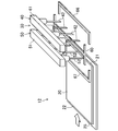
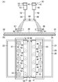
- FIG. 2 is a schematic perspective view showing a spray zone of the film forming apparatus of the first embodiment.
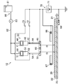
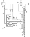
- FIG. 3 is a cross-sectional view showing the PP cross section of FIGS. 4 and 5 and the schematic configuration of the voltage application unit and the liquid supply unit.
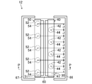
- FIG. 4 is a schematic plan view showing a spray zone of the film forming apparatus according to the first embodiment.
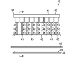
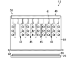
- FIG. 5 is a schematic front view showing a spray zone of the film forming apparatus of the first embodiment.
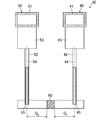
- FIG. 6 is an enlarged cross-sectional view of the main part of the PP cross section of FIGS. 4 and 5.
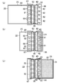
- FIG. 7A and 7B are views showing the operation of the film forming apparatus of Embodiment 1, wherein FIG. 7A is a cross-sectional view showing the PP cross section of FIGS. 4 and 5, and FIG. 7B is a spray of the film forming apparatus. It is a top view of a zone.
- FIG. 8 is a view showing the operation of the film forming apparatus of Embodiment 1, and is a cross-sectional view showing the main part of the PP cross section of FIGS. 4 and 5.
- FIG. 9 is a schematic plan view of the spray zone showing the operation of the film forming apparatus of the first embodiment.
- FIG. 10 is a cross-sectional view corresponding to FIG. 6 of the spray unit according to the first modification of the first embodiment.
- FIG. 11 is a cross-sectional view corresponding to FIG. 3 of the film forming apparatus according to the second modification of the first embodiment.
- FIG. 12 is a cross-sectional view showing a cross section corresponding to FIG. 3 of the film forming apparatus of the second embodiment.
- FIG. 13 is a schematic front view showing a spray zone of the film forming apparatus of the second embodiment.
- FIG. 14 is a cross-sectional view showing a cross-section corresponding to FIG. 12 of a film forming apparatus according to a modification of the second embodiment.
- FIG. 15 is a cross-sectional view showing an SS cross section of FIG. 17 and schematic configurations of a voltage application unit and a liquid supply unit.
- FIG. 16 is a schematic plan view illustrating a spray zone of the film forming apparatus according to the third embodiment.
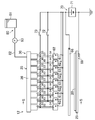
- FIG. 17 is a schematic front view illustrating a schematic configuration of a spray zone, a voltage application unit, and a liquid supply unit of the film forming apparatus of the third embodiment.
- 18A and 18B are cross-sectional views showing an enlarged main part of the spray unit of the third embodiment, where FIG. 18A shows a QQ cross section of FIG. 16, and FIG. 18B shows a RR cross section of FIG. Show.
- FIG. 19 is an enlarged cross-sectional view showing a main part of a spray unit according to a modification of the third embodiment.
- FIG. 19A shows a cross section corresponding to FIG. 18A, and FIG. A section corresponding to B) is shown.
- Embodiment 1 of the Invention A first embodiment of the present invention will be described.
- the film forming apparatus (10) of the present embodiment is for forming an antifouling film on the surface of the glass substrate (20) of the touch panel.
- the film forming apparatus (10) of the present embodiment is an electrostatic spray type component that forms a film by adhering a raw material liquid sprayed by a so-called electrostatic spray method to the surface of a glass substrate (20) as an object.
- the film-forming apparatus (10) has a pretreatment zone (11), a spray zone (12), and a posttreatment zone (13).
- the film forming apparatus (10) includes a controller (14).
- the controller (14) controls the operation of the film forming apparatus (10).
- the film forming apparatus (10) is provided with a belt conveyor (15) for conveying the glass substrate (20).
- the belt conveyor (15) is provided across the pretreatment zone (11), the spray zone (12), and the posttreatment zone (13), and the glass substrate (20) placed on the conductive plate (25) ,
- the pretreatment zone (11), the spray zone (12), and the posttreatment zone (13) are conveyed in this order. That is, the belt conveyor (15) conveys the glass substrate (20) straight from left to right in FIG.
- the belt conveyor (15) is a moving mechanism that moves the glass substrate (20) relative to a spray unit (30) described later.
- the spray zone (12) In the pretreatment zone (11), a process for cleaning the surface of the substrate is performed. In the spray zone (12), a step of attaching the raw material liquid to the surface of the substrate is performed. As will be described in detail later, the spray zone (12) is provided with a spray section (30), a voltage application section (70), and a liquid supply section (80). In the post-processing zone (13), a step of fixing the film on the glass substrate (20) is performed. Specifically, in the post-processing zone (13), the glass substrate (20) to which the raw material liquid is attached is heated.
- the spray zone (12) of the film forming apparatus (10) is provided with a spray section (30), a liquid supply section (80), and a voltage application section (70). ing.
- the conductive plate (25) on which the glass substrate (20) is placed moves straight from left to right in FIGS.
- the conductive plate (25) is a rectangular flat plate member made of a conductive resin or the like.
- the glass substrate (20) is formed in a rectangular flat plate shape.
- the spray unit (30) is disposed above the glass substrate (20).
- the spray unit (30) includes a first spray unit (40) and a second spray unit (50).
- the first spray unit (40) includes one first header member (41) and four first spray nozzles (42).
- the second spray unit (50) includes one second header member (51) and five second spray nozzles (52).
- the first spray unit (40) is arranged on the front side of the second spray unit (50) in the moving direction of the glass substrate (20) (that is, the relative moving direction of the glass substrate (20) with respect to the spraying part (30)).
- the number of spray nozzles (42, 52) provided in each spray unit (40, 50) is merely an example.
- a passage for distributing the raw material liquid to the plurality of spray nozzles (42, 52) is formed in the header member (41, 51) of each spray unit (40, 50).
- Each header member (41, 51) is disposed in a posture in which the respective axial directions are substantially orthogonal to the moving direction of the glass substrate (20). That is, the first header member (41) and the second header member (51) are in a posture in which the respective axial directions are parallel to each other, and the moving direction of the glass substrate (20) (that is, the long side of the glass substrate (20)). (Direction) with a predetermined interval.
- the first spray nozzle (42) is attached to the lower surface of the first header member (41).
- a second spray nozzle (52) is attached to the lower surface of the second header member (51).
- Each spray nozzle (42, 52) includes a base (43, 53) formed in a hollow cylindrical shape and a metal nozzle body (44, 54).
- the material of the base (43, 53) is a non-conductive resin.
- the material of the nozzle body (44, 54) may be a conductive resin.
- the nozzle body (44, 54) is a thin tube having an outer diameter of about 0.3 mm and an inner diameter of about 0.1 mm.
- Each spray nozzle (42,52) has a base (43,53) bonded to the lower surface of the header member (41,51) and a nozzle body (44,54) bonded to the lower surface of the base (43,53). Yes.
- the nozzle body (44, 54) of each spray nozzle (42, 52) has a substantially vertical direction (that is, a direction substantially perpendicular to the surface of the glass substrate (20)). .
- first spray nozzles (42) are arranged at equal intervals along the axial direction of the first header member (41).
- the interval between adjacent first spray nozzles (42) that is, the interval between the central axes of adjacent nozzle bodies (44)
- the four first spray nozzles (42) are arranged in a line at a constant pitch 2L.
- the second spray unit (50) five second spray nozzles (52) are arranged at equal intervals along the axial direction of the second header member (51).
- the interval between the adjacent second spray nozzles (52) (that is, the interval between the central axes of the adjacent nozzle bodies (54)) is 2L. That is, in the second spray unit (50), the five second spray nozzles (52) are arranged in a line at a constant pitch 2L.
- the position of the first spray nozzle (42) in the first spray unit (40) is shifted by a half pitch with respect to the position of the second spray nozzle (52) in the second spray unit (50) (see FIG. 4). ).
- the first spray nozzle (42) and the second spray nozzle (52) in a direction orthogonal to the moving direction of the glass substrate (20) that is, the short side direction of the glass substrate (20)).
- the distance between the first spray nozzle (42) and the second spray nozzle (52) adjacent in the short side direction of the glass substrate (20) that is, the central axis of the nozzle body (44) and the nozzle body
- the interval between the central axes of (54) is L.
- the 1st header member (41) of the 1st spray unit (40) and the 2nd header member (51) of the 2nd spray unit (50) are glass substrates. They are arranged at a predetermined interval in the long side direction of (20). Therefore, the position of the lower end of the first spray nozzle (42) attached to the first header member (41) (that is, the lower end of the nozzle body (44)) and the first attached to the second header member (51). The position of the lower end of the two spray nozzles (52) (that is, the lower end of the nozzle body (54)) is shifted in the moving direction of the glass substrate (20).
- the front end surface (45, 55) of the nozzle body (44, 54) of each spray nozzle (42, 52) is inclined with respect to the central axis of the nozzle body (44, 54). .
- the inclination angle of the distal end surface (45) with respect to the center axis of the nozzle body (44) is theta 1.
- the inclination angle of the distal end surface (55) with respect to the center axis of the nozzle body (54) is a theta 2.
- Inclination angle theta 1 of the distal end surface of the nozzle body (44) (45) is equal to the inclination angle theta 2 of the distal end surface of the nozzle body (54) (55).
- each 1st spray nozzle (42) of a 1st spray unit (40) the front end surface (45) of a nozzle main body (44) faces the front side (right side in FIG. 6) of the moving direction of a glass substrate (20). Yes.
- the tip surface (55) of the nozzle body (54) faces the rear side (left side in FIG. 6) of the movement direction of the glass substrate (20). ing.
- tip (lower end in FIG.3 and FIG.5) of the nozzle main body (44,54) of each spray nozzle (42,52) to the surface of a glass substrate (20). D are equal to each other.
- the liquid supply part (80) includes a tank (81), an infusion pipe (82), and a pump (83).
- the tank (81) stores the raw material liquid.
- the raw material liquid is obtained by diluting a substance that forms an antifouling film with a solvent.
- One end of the infusion piping (82) is connected to the bottom of the tank (81), and the other end is connected to the header member (41, 51) of each spray unit (40, 50).
- the pump (83) is provided in the infusion pipe (82) and discharges the raw material liquid sucked from the tank (81) toward the header member (41, 51).
- the voltage application unit (70) includes a power source (71), a ground electrode (68), a first switch (72), and a second switch (73).
- the voltage application unit (70) includes one upper electrode (60) and two lower electrodes (66, 67).
- the power supply (71) is a DC power supply with an output voltage of about 5 kV.
- the positive electrode (+ electrode) of the power source (71) is connected to the nozzle bodies (44) of all the first spray nozzles (42) via the first switch (72) and to all nozzles (44) via the second switch (73).
- Each of the two spray nozzles (52) is electrically connected to the nozzle body (54).
- the negative (-) pole of the power source (71) is grounded.
- the ground electrode (68) is grounded in the same manner as the negative electrode of the power source (71).
- the ground electrode (68) is disposed below the conductive plate (25) and contacts the lower surface of the conductive plate (25) conveyed by the belt conveyor (15). That is, the ground electrode (68) is electrically connected to the conductive plate (25), and the conductive plate (25) has the same potential as the ground electrode (68).
- the upper electrode (60) is a member made of conductive resin formed in a rod shape, and is formed in an I shape in plan view.
- the upper electrode (60) is disposed between the tip of the nozzle body (44) of the first spray nozzle (42) and the tip of the nozzle body (54) of the second spray nozzle (52). That is, in the moving direction of the glass substrate (20), the upper electrode (60) is located behind the tip of the nozzle body (44) of the first spray nozzle (42) and the second spray nozzle (52). Located in front of the tip of the nozzle body (54). Further, as shown in FIGS.
- the upper electrode (60) is electrically connected to the positive electrode of the power source (71).
- the upper electrode (60) serves as a first deflection electrode corresponding to the first spray nozzle (42) and a second deflection electrode corresponding to the second spray nozzle (52).
- each lower electrode (66, 67) is a member made of conductive resin formed in a rod shape, and is formed in a rod shape extending in the short side direction of the glass substrate (20). ing. Each lower electrode (66, 67) is disposed below the upper electrode (60) and closer to the glass substrate (20). The first lower electrode (66) is disposed on the front side of the first spray nozzle (42) in the moving direction of the glass substrate (20). The second lower electrode (67) is arranged behind the second spray nozzle (52) in the moving direction of the glass substrate (20).
- both ends of the first lower electrode (66) are bent substantially at right angles to the second lower electrode (67) side, and both ends of the first lower electrode (67) are directed to the first lower electrode (66) side. It is bent at a right angle.
- the first lower electrode (66) and the second lower electrode (67) are electrically connected to the positive electrode of the power source (71).
- the film forming apparatus (10) includes the step of cleaning the glass substrate (20) in the pretreatment zone (11) and the step of attaching the raw material liquid to the glass substrate (20) in the spray zone (12). Then, the step of fixing the film to the glass substrate (20) in the post-treatment zone (13) is performed.
- the operation performed by the film forming apparatus (10) to adhere the raw material liquid to the glass substrate (20) in the spray zone (12) will be described.
- the film forming apparatus (10) executes a film forming method as described below.
- each spray nozzle (42,52) When both the first switch (72) and the second switch (73) are in the ON state, the nozzle body (44,54) of each spray nozzle (42,52) is electrically connected to the positive electrode of the power supply (71). To do. Further, the conductive plate (25) on which the glass substrate (20) is placed is electrically connected to the ground electrode (68). For this reason, a voltage is applied between the nozzle body (44, 54) of each spray nozzle (42, 52) and the glass substrate (20) mounted on the conductive plate (25).
- the tip surface (45) of the nozzle body (44) faces the front side in the moving direction of the glass substrate (20). For this reason, droplet-form raw material liquid is sprayed from the nozzle body (44) in the moving direction of the glass substrate (20).
- the tip surface (55) of the nozzle body (54) faces the rear side in the moving direction of the glass substrate (20). For this reason, droplet-form raw material liquid is sprayed from the nozzle body (54) in the direction opposite to the moving direction of the glass substrate (20).
- the liquid material sprayed from the nozzle body (44, 54) has a positive (+) charge. is doing.
- An electrical repulsive force acts between the liquid material in the form of droplets having a positive (+) charge and the upper electrode (60) that is electrically connected to the positive electrode of the power source (71).
- the distance G 1 between the center axis of the nozzle body (44) to the surface of the upper electrode (60) the distance G 2 from the central axis of the nozzle body (54) to the surface of the upper electrode (60) equal.
- the Coulomb force in the direction of separating the droplet from the upper electrode (60) acts on the droplet sprayed from the nozzle body (44, 54) of each spray nozzle (42, 52). For this reason, the droplet sprayed from the nozzle body (44) of the first spray nozzle (42) is scattered in the direction opposite to the upper electrode (60) (that is, the moving direction of the glass substrate (20)). Go. Further, the droplet sprayed from the nozzle body (54) of the second spray nozzle (52) is directed in the direction opposite to the upper electrode (60) (that is, the direction opposite to the moving direction of the glass substrate (20)). Will be scattered.
- an electrical repulsive force acts between the liquid raw material having a positive charge and the lower electrodes (66, 67) that are electrically connected to the positive electrode of the power source (71). That is, the Coulomb force in the direction opposite to the moving direction of the glass substrate (20) is applied to the droplet sprayed from the nozzle body (44) of the first spray nozzle (42) and reaching the vicinity of the surface of the glass substrate (20). Works. For this reason, the excessive spreading
- the repulsive force acting during) is almost equal.
- the spray direction of the raw material liquid from the first spray nozzle (42) and the spray direction of the raw material liquid from the second spray nozzle (52) are the upper electrode (60).
- the reaching area (91, 92) which is the area where the droplet-shaped raw material liquid sprayed from each spray nozzle (42, 52) reaches, is a substantially circular area.
- the liquid material in the form of droplets sprayed from the first spray nozzle (42) scatters obliquely downward to the right in the figure, while the second spray nozzle (52 The liquid material in the form of droplets sprayed from) scatters toward the lower left of the figure.
- region (91) which is an area
- the second reaching region (92) is separated in the long side direction of the glass substrate (20). That is, the attachment position of the raw material liquid sprayed from the first spray nozzle (42) to the glass substrate (20) and the attachment position of the raw material liquid sprayed from the second spray nozzle (52) to the glass substrate (20). Is shifted in the moving direction of the glass substrate (20).
- the adjacent reaching regions (91, 92) are arranged in a line in the short side direction of the glass substrate (20), the adjacent reaching regions (91, 92) The interval is substantially zero.
- the position of the first arrival region (91) corresponding to the first spray nozzle (42) and the second arrival region (corresponding to the second spray nozzle (52)) ( 92) is shifted in the long side direction of the glass substrate (20). For this reason, in the film-forming apparatus (10) of this embodiment, as shown to FIG. 7 (B), the space
- the conductive plate (25) on which the glass substrate (20) is placed is conveyed to the spray zone (12) by the belt conveyor (15).
- the front edge (21) of the glass substrate (20) Enters the second arrival area (92) and then enters the first arrival area (91).
- the first arrival region (91) is a region where droplets sprayed from the first spray nozzle (42) reach
- the second arrival region (92) is the second spray nozzle ( This is the area where droplets sprayed from (52) reach.
- both the first switch (72) and the second switch (73) are in the OFF state. Spraying of the raw material liquid from the spray nozzle (42) and the second spray nozzle (52) is stopped.
- the second switch (73) is switched to the ON state, and the second spray nozzle Spraying of the raw material liquid from (52) is started.
- FIG. 9 (a) when the glass substrate (20) moves while the raw material liquid is sprayed from the second spray nozzle (52), each of the glass substrates (20) is moved from the front edge (21). The raw material liquid adheres to the band-like region that reaches the two reaching region (92).
- the spray section (30) first starts spraying the raw material liquid from the second spray nozzle (52), and thereafter The spraying of the raw material liquid from the spray nozzle (42) is started.
- the film forming apparatus (10) of the present embodiment a sufficient interval between the first reaching region (91) and the second reaching region (92) adjacent in the short side direction of the glass substrate (20) is secured. Therefore, the repulsive force acting between the droplet sprayed from the first spray nozzle (42) and the droplet sprayed from the second spray nozzle (52) becomes substantially zero. Therefore, on the surface of the glass substrate (20), there are a region where the raw material liquid sprayed from the first spray nozzle (42) is attached and a region where the raw material liquid sprayed from the second spray nozzle (52) is attached. There is no region between which the raw material liquid does not adhere.
- the rear edge (22) of the glass substrate (20) (that is, the rear edge in the moving direction of the glass substrate (20)) reaches the second arrival region (92).
- the raw material liquid is sprayed from both the first spray nozzle (42) and the second spray nozzle (52).
- the second switch (73) is turned off, and the second spray nozzle (52 The spraying of the raw material liquid from) stops.
- the band-shaped region corresponding to the second reaching region (92) of the surface of the glass substrate (20) is the raw material on the entire surface from the front edge (21) to the rear edge (22) of the glass substrate (20). The liquid has adhered (refer FIG.9 (c)).
- the glass substrate (20) moves while the raw material liquid is sprayed from the first spray nozzle (42).
- the raw material liquid adheres to the portion corresponding to the first reaching region (91) on the surface of the glass substrate (20).
- the first switch (72) is turned off, and the spray of the raw material liquid from the first spray nozzle (42) is performed. Stop.
- the glass substrate (20) is in a state where the raw material liquid is attached to the entire surface.
- the spraying part (30) first stops the spraying of the raw material liquid from the second spraying nozzle (52), and thereafter The spraying of the raw material liquid from the spray nozzle (42) is stopped.
- the first switch (72) and the second switch (73) are either in the ON state or the OFF state depending on the position of the glass substrate (20). Is set. The operation of the first switch (72) and the second switch (73) is performed by the controller (14).
- the first spray nozzle (42) and the second spray nozzle (52) are alternately arranged in the direction intersecting with the moving direction of the glass substrate (20), and the first reaching region is obtained. (91) and the second reaching region (92) are shifted in the moving direction of the glass substrate (20).
- the first reaching region (91) is a region where the droplet sprayed from the first spray nozzle (42) reaches, and the second reaching region (92) is sprayed from the second spray nozzle (52). This is the area where the droplets reach.
- the distance between the charged droplet sprayed from the first spray nozzle (42) and the charged droplet sprayed from the second spray nozzle (52) is sufficient.
- the electrical repulsive force acting between the droplet sprayed from the first spray nozzle (42) and the droplet sprayed from the second spray nozzle (52) can be reduced. it can. Therefore, in the film forming apparatus (10) of the present embodiment, the droplets sprayed from each spray nozzle are repelled to prevent the formation of a region where the raw material liquid does not adhere to the surface of the glass substrate (20). And a film can be reliably formed on the entire surface of the glass substrate (20).
- the potential of the upper electrode (60) has the same polarity as the potential of the droplet sprayed from each spray nozzle (42, 52). For this reason, an electrical repulsive force acts between the droplet sprayed from each spray nozzle (42, 52) and the upper electrode (60). That is, a Coulomb force in the moving direction of the glass substrate (20) acts on the droplet sprayed from the first spray nozzle (42), and a glass sprayed on the droplet sprayed from the second spray nozzle (52). Coulomb force in the direction opposite to the moving direction of the substrate (20) acts.
- the droplet sprayed from the 1st spray nozzle (42) can be reliably scattered toward the moving direction of a glass substrate (20), and it can be made from the 2nd spray nozzle (52).
- the sprayed droplets can be reliably scattered in the direction opposite to the moving direction of the glass substrate (20).
- the film forming apparatus (10) as described above, the distance G 1 between the center axis of the nozzle body (44) of the first spray nozzle (42) to the surface of the upper electrode (60), the distance G 2 from the central axis of the nozzle body (54) of the second spray nozzle (52) to the surface of the upper electrode (60) are equal.
- the time until the droplet sprayed from the first spray nozzle (42) reaches the surface of the glass substrate (20) and the droplet sprayed from the second spray nozzle (52) The time to reach the surface of) is almost the same.
- the difference from the diameter of the droplet reaching the surface of (20) can be made as small as possible.
- the first spray nozzle that sprays the raw material liquid in the moving direction of the glass substrate (20) in the process in which the glass substrate (20) approaches the spray unit (30).
- the 1st spray nozzle (42) which sprays a raw material liquid in the moving direction of a glass substrate (20) in the process in which a glass substrate (20) leaves
- the timing of stopping the spraying of the raw material liquid from the second is later than the timing of stopping the spraying of the raw material liquid from the second spray nozzle (52) that sprays the raw material liquid in the direction opposite to the moving direction of the glass substrate (20). It has become. Therefore, according to the present embodiment, the raw material liquid sprayed from the spray nozzle (42, 52) when the glass substrate (20) is located in a region where the raw material liquid sprayed from the spray nozzle (42, 52) does not reach. The amount of raw material liquid that is wasted without adhering to the glass substrate (20) can be reduced.
- the tip surface (45,55) of the nozzle body (44,54) of each spray nozzle (42,52) 54) may be orthogonal to the central axis.
- an electric repulsive force acts between the droplet sprayed from each spray nozzle (42, 52) and the upper electrode (60). Therefore, also in this modification, the droplet sprayed from the first spray nozzle (42) is scattered in the direction away from the upper electrode (60) (that is, the moving direction of the glass substrate (20)), and the second spray.
- the droplet sprayed from the nozzle (52) is scattered in a direction away from the upper electrode (60) (that is, a direction opposite to the moving direction of the glass substrate (20)).
- the central axis of the nozzle body (44, 54) of each spray nozzle (42, 52) is inclined with respect to the surface of the glass substrate (20). You may do it.
- the nozzle body (44) of each first spray nozzle (42) is positioned so that the distal end is located on the front side in the movement direction of the glass substrate (20) relative to the base end. Inclined.
- the nozzle body (54) of each second spray nozzle (52) has its tip positioned behind the base end in the movement direction of the glass substrate (20). Inclined to do.
- Embodiment 2 of the Invention A second embodiment of the present invention will be described. Here, the difference between the film forming apparatus (10) of the present embodiment and the film forming apparatus (10) of the first embodiment will be described.
- a shielding plate (69) is provided instead of the upper electrode (60).
- the shielding plate (69) is a plate-like member provided between the first spray unit (40) and the second spray unit (50), and includes the first spray unit (40) and the second spray unit ( 50) constitutes a shielding member that shields the gap.
- the shielding plate (69) is a member formed in a rectangular thick plate shape, and is arranged so as to shield between the first spray unit (40) and the second spray unit (50). .
- the length of the long side of the shielding plate (69) is slightly longer than the length of the header member (41, 51).
- the shielding plate (69) has an upper end located between the first header member (41) and the second header member (51), and a lower end thereof, the first lower electrode (66) and the second lower electrode. Located between (67).
- the material of the shielding plate (69) is a non-conductive resin. Unlike the upper electrode (60), the shielding plate (69) is not connected to the power source (71).
- the first spray unit (40) and the second spray unit (50) are shielded by the shielding plate (69) made of a non-conductive material.
- the electric field formed near the tip of each spray nozzle is blocked by the shielding plate (69). Therefore, the influence of the electric field in the vicinity of one end of the first spray nozzle (42) and the second spray nozzle (52) on the spray state of the raw material liquid from the other is substantially eliminated.
- the raw material from the second spray nozzle (52) can be kept constant, and as a result, the thickness of the film formed on the surface of the glass substrate (20) can be made uniform.
- the material of the shielding plate (69) may be metal or conductive resin, and the shielding plate (69) may be electrically connected to the positive electrode of the power source (71).
- the potential of the shielding plate (69) of this modification is the same polarity as the potential of the droplet sprayed from the spray nozzle (42, 52). For this reason, an electrical repulsive force acts between the droplet sprayed from the spray nozzle (42, 52) and the shielding plate (69). Therefore, according to this modification, the spray direction of the raw material liquid from the spray nozzle (42, 52) can be stabilized.
- Embodiment 3 of the Invention will be described.
- the film forming apparatus (10) of the present embodiment will be described with respect to differences from the film forming apparatus (10) of the first embodiment.
- the film forming apparatus (10) of the present embodiment is provided with one spray unit (35) instead of the first spray unit (40) and the second spray unit (50). It is done.
- the spray unit (35) includes one header member (36), four first spray nozzles (42), and five second spray nozzles (52).
- a passage for distributing the raw material liquid to the plurality of spray nozzles (42, 52) is formed in the header member (36) of the spray unit (35).
- the header member (36) is arranged in a posture in which its axial direction is substantially orthogonal to the moving direction of the glass substrate (20).
- the infusion piping (82) is connected to the header member (36).
- the first spray nozzle (42) and the second spray nozzle (52) are attached to the lower surface of the header member (36).
- the base (43,53) is joined to the lower surface of the header member (36), and the nozzle body (44,54) is joined to the lower surface of the base (43,53).
- the nozzle body (44, 54) of each spray nozzle (42, 52) has a substantially vertical direction (that is, a direction substantially perpendicular to the surface of the glass substrate (20)). .
- the first spray nozzle (42) and the second spray nozzle (52) are alternately arranged at equal intervals along the axial direction of the header member (36). .
- the distance between the adjacent first spray nozzle (42) and the second spray nozzle (52) that is, the distance between the central axis of the adjacent nozzle body (44) and the central axis of the nozzle body (54)).
- Is L that is, in the spray unit (35), the four first spray nozzles (42) and the five second spray nozzles (52) are alternately arranged in a line at a constant pitch L.
- each first spray nozzle (42) has the front end surface (45) of the nozzle body (44) facing the front side (right side in FIG. 18) of the movement direction of the glass substrate (20).
- the tip end surface (55) of the nozzle body (54) faces the rear side (left side in FIG. 18) of the movement direction of the glass substrate (20).
- each first spray nozzle (42) is electrically connected to the positive electrode of the power source (71) via the first switch (72), and each second nozzle The nozzle body (54) of the spray nozzle (52) is electrically connected to the positive electrode of the power source (71) via the second switch (73).
- the film forming apparatus (10) of this embodiment has four (that is, the same number as the first spray nozzle (42)) instead of one upper electrode (60).
- the first upper electrode (61) and five (that is, the same number as the second spray nozzle (52)) second upper electrodes (62) are provided.
- Each upper electrode (61, 62) is a small rectangular plate-shaped member.
- the material of each upper electrode (61, 62) is metal or conductive resin.
- the first upper electrode (61) is a first deflecting electrode, and is located behind each first spray nozzle (42) in the moving direction of the glass substrate (20).
- the four first upper electrodes (61) are arranged in a row along the longitudinal direction of the header member (36) in a standing posture in which the respective width directions are parallel to the longitudinal direction of the header member (36).
- the upper end of each first upper electrode (61) is located above the lower end of the nozzle body (44) of the corresponding first spray nozzle (42).
- Each first upper electrode (61) is electrically connected to the positive electrode of the power source (71) (see FIG. 17). Therefore, the potential of the first upper electrode (61) has the same polarity as the potential of the droplet sprayed from the first spray nozzle (42).
- the second upper electrode (62) is a second deflecting electrode, and is provided in front of each second spray nozzle (52) in the moving direction of the glass substrate (20).
- the five second upper electrodes (62) are arranged in a line along the longitudinal direction of the header member (36) in a standing posture in which the respective width directions are parallel to the longitudinal direction of the header member (36).
- the upper end of each second upper electrode (62) is located above the lower end of the nozzle body (54) of the corresponding second spray nozzle (52).
- Each second upper electrode (62) is electrically connected to the positive electrode of the power source (71) (see FIG. 17). Therefore, the potential of the second upper electrode (62) has the same polarity as the potential of the droplet sprayed from the second spray nozzle (52).
- the liquid material droplets sprayed from the spray nozzles (42, 52) have a positive (+) charge. Therefore, an electric repulsive force acts between the droplet sprayed from each first spray nozzle (42) and the first upper electrode (61) corresponding to the first spray nozzle (42). For this reason, the droplet sprayed from each first spray nozzle (42) moves away from the first upper electrode (61) corresponding to the first spray nozzle (42) (that is, movement of the glass substrate (20)). (Direction). An electric repulsive force acts between the droplet sprayed from each second spray nozzle (52) and the second upper electrode (62) corresponding to the second spray nozzle (52). For this reason, the droplet sprayed from each second spray nozzle (52) moves away from the second upper electrode (62) corresponding to the second spray nozzle (52) (that is, movement of the glass substrate (20)). It scatters in the direction opposite to the direction.
- the position of the first arrival region (91) corresponding to each first spray nozzle (42) is the same as the film forming apparatus (10) of the first embodiment.
- region (92) corresponding to each 2nd spray nozzle (52) shifts
- the first reaching region (91) is a region where the droplet sprayed from the first spray nozzle (42) reaches, and the second reaching region (92) is sprayed from the second spray nozzle (52). This is the area where the droplets reach.
- the tip surfaces (45, 55) of the nozzle bodies (44, 54) of the spray nozzles (42, 52) 54) may be orthogonal to the central axis.
- the droplet sprayed from the first spray nozzle (42) is scattered in the direction away from the first upper electrode (61) (that is, the moving direction of the glass substrate (20)),
- the droplets sprayed from the two spray nozzles (52) are scattered in the direction away from the second upper electrode (62) (that is, the direction opposite to the moving direction of the glass substrate (20)).
- the film forming apparatus (10) of each of the above embodiments is configured to move the glass substrate (20) while fixing the spray unit (30), but on the contrary, the glass substrate (20) is moved.
- the spray unit (30) may be configured to be fixed and moved.
- the present invention is useful for a film forming apparatus and a film forming method for forming a film on an object by electrostatic spraying.
- Film deposition equipment 15 Belt conveyor (movement mechanism) 20 Glass substrate (object) 30 Spraying portion 41 First header member 42 First spray nozzle 45 Tip surface 51 Second header member 52 Second spray nozzle 55 Tip surface 60 Upper electrode (deflection electrode) 61 First upper electrode (deflection electrode) 62 Second upper electrode (electrode for deflection) 69 Shield plate (shield member) 70 Voltage application section
Landscapes
- Electrostatic Spraying Apparatus (AREA)
- Application Of Or Painting With Fluid Materials (AREA)
Abstract
成膜装置(10)では、対象物(20)と噴霧部(30)の一方が他方に対して相対的に移動する。噴霧部(30)では、第1噴霧ノズル(42)と第2噴霧ノズル(52)が、噴霧部(30)に対する対象物(20)の相対的な移動方向と交わる方向に交互に配置される。各噴霧ノズル(42,52)から噴霧された原料液は、対象物(20)の表面に付着して被膜を形成する。各噴霧ノズル(42,52)から噴霧された原料液の対象物(20)への付着位置は、噴霧部(30)に対する対象物(20)の相対的な移動方向に、互いにずれている。その結果、対象物の表面全体に確実に被膜が形成される。
Description
本発明は、静電噴霧によって対象物に被膜を形成する成膜装置および成膜方法に関するものである。
従来より、いわゆる静電噴霧法を用いて原料液を霧化し、霧化した原料液を対象物に付着させることによって被膜を形成する成膜装置が知られている。特許文献1には、広い面に被膜を形成するために、一列に並んだ複数の開口から原料液を噴霧する成膜装置が開示されている。
ところで、静電噴霧法を用いて原料液を霧化する場合、開口から噴霧された液滴は帯電している。また、開口から噴霧された無数の液滴は、概ね円錐状に広がりながら飛翔して対象物に付着する。このため、対象物の表面付近では、隣り合う開口から噴霧された液滴同士の距離が短くなる。
一方、各開口から噴出した液滴は、同じ極性の電荷を帯びている。従って、対象物の表面付近において隣り合う開口から噴霧された液滴同士が接近すると、各液滴には、互いに反発する方向のクーロン力が作用する。このため、一列に並んだ複数の開口から原料液を噴霧する場合、対象物の表面では、隣り合う開口の間に位置する部分へ液滴が殆ど到達せず、対象物の表面全体に被膜を形成できないおそれがあった。
本発明は、かかる点に鑑みてなされたものであり、その目的は、静電噴霧法によって複数箇所から原料液を噴霧して対象物に被膜を形成する場合に、対象物の表面全体に確実に被膜を形成することにある。
第1の発明は、対象物(20)に原料液を噴霧することによって該対象物(20)の表面に被膜を形成する静電噴霧型の成膜装置を対象とする。そして、複数の噴霧ノズル(42,52)を有する噴霧部(30)と、上記原料液が帯電した液滴となって上記噴霧ノズル(42,52)から上記対象物(20)へ噴霧されるように上記噴霧ノズル(42,52)と上記対象物(20)の間に電圧を印加する電圧印加部(70)と、上記対象物(20)と上記噴霧部(30)の一方を他方に対して相対的に移動させる移動機構(15)をと備え、上記噴霧部(30)は、第1の噴霧ノズル(42)と第2の噴霧ノズル(52)とが、上記噴霧部(30)に対する上記対象物(20)の相対的な移動方向と交わる方向に交互に配置され、上記第1の噴霧ノズル(42)から噴霧された原料液の上記対象物(20)への付着位置と、上記第2の噴霧ノズル(52)から噴霧された原料液の上記対象物(20)への付着位置とが、上記噴霧部(30)に対する上記対象物(20)の相対的な移動方向にずれているものである。
第1の発明の成膜装置(10)は、噴霧部(30)に第1の噴霧ノズル(42)と第2の噴霧ノズル(52)とが設けられる。電圧印加部(70)が噴霧ノズル(42,52)と対象物(20)の間に電圧を印加すると、原料液が噴霧ノズル(42,52)から噴霧される。対象物(20)の表面には、噴霧ノズル(42,52)から噴霧された液滴状の原料液が付着し、付着した原料液によって被膜が形成される。また、この発明において、移動機構(15)は、対象物(20)と噴霧部(30)の一方を他方に対して相対的に移動させる。噴霧ノズル(42,52)から原料液が噴霧されている状態で対象物(20)が噴霧部(30)に対して相対的に移動すると、対象物(20)の表面では、各噴霧ノズル(42,52)に対応する帯状の領域に原料液が付着する。
第1の発明の噴霧部(30)では、噴霧部(30)に対する対象物(20)の相対的な移動方向と交わる方向において、第1の噴霧ノズル(42)と第2の噴霧ノズル(52)とが交互に配置される。隣り合う第1の噴霧ノズル(42)と第2の噴霧ノズル(52)は、それぞれから噴霧された原料液の対象物(20)への付着位置が、噴霧部(30)に対する対象物(20)の相対的な移動方向において相違する。このため、各噴霧ノズル(42,52)から噴霧された原料液の対象物(20)への付着位置が噴霧部(30)に対する対象物(20)の相対的な移動方向と交わる方向に一直線上に並んでいる場合に比べると、対象物(20)の表面付近では、第1の噴霧ノズル(42)から噴霧された液滴状の原料液と、第2の噴霧ノズル(52)から噴霧された液滴状の原料液との距離が長くなる。従って、第1の噴霧ノズル(42)から噴霧された液滴状の原料液と、第2の噴霧ノズル(52)から噴霧された液滴状の原料液との間に作用する電気的な斥力が小さくなり、対象物(20)の表面の全体に原料液が付着する。
第2の発明は、上記第1の発明において、上記第1の噴霧ノズル(42)は、上記噴霧部(30)に対する上記対象物(20)の相対的な移動方向に向かって上記原料液を噴霧し、上記第2の噴霧ノズル(52)は、上記噴霧部(30)に対する上記対象物(20)の相対的な移動方向とは逆向きに上記原料液を噴霧するものである。
第2の発明では、噴霧部(30)に対する対象物(20)の相対的な移動方向において、第1の噴霧ノズル(42)からの原料液の噴霧方向と、第2の噴霧ノズル(52)からの原料液の噴霧方向とが、逆向きとなる。このため、対象物(20)の表面付近では、第1の噴霧ノズル(42)から噴霧された液滴状の原料液と、第2の噴霧ノズル(52)から噴霧された液滴状の原料液との距離が長くなる。その結果、第1の噴霧ノズル(42)から噴霧された液滴状の原料液と、第2の噴霧ノズル(52)から噴霧された液滴状の原料液との間に作用する電気的な斥力が小さくなる。
第3の発明は、上記第2の発明において、上記第1の噴霧ノズル(42)は、該第1の噴霧ノズル(42)の軸心に対して傾斜した先端面(45)が上記噴霧部(30)に対する上記対象物(20)の相対的な移動方向の前側を向くように配置され、上記第2の噴霧ノズル(52)は、該第2の噴霧ノズル(52)の軸心に対して傾斜した先端面(55)が上記噴霧部(30)に対する上記対象物(20)の相対的な移動方向の後側を向くように配置されるものである。
第3の発明において、各噴霧ノズル(42,52)は、それぞれの軸方向に対して先端面(45,55)が傾斜している。噴霧部(30)に対する対象物(20)の相対的な移動方向において、第1の噴霧ノズル(42)の先端面(45)と、第2の噴霧ノズル(52)の先端面(55)とは、逆側を向いている。第1の噴霧ノズル(42)は、噴霧部(30)に対する対象物(20)の相対的な移動方向の前側を向いた先端面(45)から原料液を噴霧する。一方、第2の噴霧ノズル(52)は、噴霧部(30)に対する対象物(20)の相対的な移動方向の後側を向いた先端面(55)から原料液を噴霧する。
第4の発明は、上記第2又は第3の発明において、上記噴霧部(30)に対する上記対象物(20)の相対的な移動方向における上記第1の噴霧ノズル(42)の先端の後側に配置され、該第1の噴霧ノズル(42)から噴霧される液滴と電位が同極性の第1の偏向用電極(60,61)と、上記噴霧部(30)に対する上記対象物(20)の相対的な移動方向における上記第2の噴霧ノズル(52)の先端の前側に配置され、該第2の噴霧ノズル(52)から噴霧される液滴と電位が同極性の第2の偏向用電極(60,62)とを備えるものである。
第4の発明では、成膜装置(10)に偏向用電極(60,61,62)が設けられる。各偏向用電極(60,61,62)の電位は、対応する噴霧ノズル(42,52)から噴霧される液滴の電位と同極性である。噴霧部(30)に対する対象物(20)の相対的な移動方向において、第1の偏向用電極(60,61)は、第1の噴霧ノズル(42)の先端の後側に配置される。第1の噴霧ノズル(42)から噴霧された液滴状の原料液と第1の偏向用電極(60,61)との間には、電気的な斥力が作用する。このため、第1の噴霧ノズル(42)から噴霧された液滴状の原料液は、噴霧部(30)に対する対象物(20)の相対的な移動方向へ向かって飛散する。一方、噴霧部(30)に対する対象物(20)の相対的な移動方向において、第2の偏向用電極(60,62)は、第2の噴霧ノズル(52)の先端の前側に配置される。第2の噴霧ノズル(52)から噴霧された液滴状の原料液と第2の偏向用電極(60,62)との間に、電気的な斥力が作用する。このため、第2の噴霧ノズル(52)から噴霧された液滴状の原料液は、噴霧部(30)に対する対象物(20)の相対的な移動方向とは逆方向へ飛散する。
第5の発明は、上記第2~第4のいずれか一つの発明において、上記対象物(20)が上記噴霧部(30)に相対的に近付いてくるときには、上記第2の噴霧ノズル(52)からの上記原料液の噴霧を開始した後に上記第1の噴霧ノズル(42)からの上記原料液の噴霧を開始し、上記対象物(20)が上記噴霧部(30)から相対的に離れてゆくときには、上記第2の噴霧ノズル(52)からの上記原料液の噴霧を停止した後に上記第1の噴霧ノズル(42)からの上記原料液の噴霧を停止するものである。
ここで、噴霧部(30)に相対的に近付いてくる対象物(20)は、先ず第2の噴霧ノズル(52)から噴霧された原料液の到達する領域に入り、その後に第1の噴霧ノズル(42)から噴霧された原料液の到達する領域に入る。また、噴霧部(30)に相対的に離れてゆく対象物(20)は、先ず第2の噴霧ノズル(52)から噴霧された原料液の到達する領域から外れ、その後に第1の噴霧ノズル(42)から噴霧された原料液の到達する領域から外れる。一方、噴霧ノズル(42,52)から噴霧された原料液が到達しない領域に対象物(20)が存在する場合には、噴霧ノズル(42,52)から噴霧された原料液が対象物(20)に付着しない。従って、この場合に噴霧ノズル(42,52)から原料液を噴霧し続けると、原料液が無駄となる。
そこで、第5の発明では、対象物(20)が噴霧部(30)に相対的に近付いてくるときには、先ず第2の噴霧ノズル(52)からの原料液の噴霧を開始し、その後に第1の噴霧ノズル(42)からの原料液の噴霧を開始する。つまり、第2の噴霧ノズル(52)から噴霧された原料液の到達する領域だけに対象物(20)が存在する間は、第1の噴霧ノズル(42)からの原料液の噴霧を停止し、第2の噴霧ノズル(52)から原料液を噴霧する。そして、第1及び第2の噴霧ノズル(42,52)から噴霧された原料液の到達する領域に対象物(20)が存在する間は、第1及び第2の噴霧ノズル(42,52)から原料液を噴霧する。
また、第5の発明では、対象物(20)が噴霧部(30)から相対的に離れてゆくときには、先ず第2の噴霧ノズル(52)からの原料液の噴霧を停止し、その後に第1の噴霧ノズル(42)からの原料液の噴霧を停止する。つまり、第1及び第2の噴霧ノズル(42,52)から噴霧された原料液の到達する領域に対象物(20)が存在する間は、第1及び第2の噴霧ノズル(42,52)から原料液を噴霧する。そして、第1の噴霧ノズル(42)から噴霧された原料液の到達する領域だけに対象物(20)が存在する間は、第2の噴霧ノズル(52)からの原料液の噴霧を停止し、第1の噴霧ノズル(42)から原料液を噴霧する。
第6の発明は、上記第1~第5のいずれか一つの発明において、上記第1の噴霧ノズル(42)の先端の位置と、上記第2の噴霧ノズル(52)の先端の位置とが、上記噴霧部(30)に対する上記対象物(20)の相対的な移動方向にずれているものである。
第6の発明では、噴霧部(30)に対する対象物(20)の相対的な移動方向において、第1の噴霧ノズル(42)の先端の位置と、第2の噴霧ノズル(52)の先端の位置とが相違する。噴霧部(30)に対する対象物(20)の相対的な移動方向における位置が互いに異なる各噴霧ノズル(42,52)の先端から、原料液が噴霧される。
第7の発明は、上記第6の発明において、上記第1の噴霧ノズル(42)と上記第2の噴霧ノズル(52)の間を遮蔽する遮蔽部材(69)を備えるものである。
第7の発明では、遮蔽部材(69)が第1の噴霧ノズル(42)と第2の噴霧ノズル(52)の間を遮る。第1の噴霧ノズル(42)からは、遮蔽部材(69)の一方の側へ向かって原料液が噴霧され、第2の噴霧ノズル(52)からは、遮蔽部材(69)の他方の側へ向かって原料液が噴霧される。つまり、遮蔽部材(69)は、第1の噴霧ノズル(42)から噴霧された液滴状の原料液と、第2の噴霧ノズル(52)から噴霧された液滴状の原料液との間を遮る。
第8の発明は、上記第7の発明において、上記遮蔽部材(69)には、該遮蔽部材(69)の電位が上記噴霧ノズル(42,52)から噴霧された液滴の電位と同極性となるように電圧が印加されるものである。
第8の発明では、遮蔽部材(69)に電圧が印加される。遮蔽部材(69)の電位は、噴霧ノズルから噴霧された液滴の電位と同極性である。このため、各噴霧ノズル(42,52)から噴霧された液滴と遮蔽部材(69)とには、電気的な斥力が作用する。つまり、各噴霧ノズル(42,52)から噴霧された液滴には、液滴を遮蔽部材(69)から遠ざける方向のクーロン力が作用する。
第9の発明は、上記第1~第8のいずれか一つの発明において、上記噴霧部(30)は、全ての上記第1の噴霧ノズル(42)に接続して各第1の噴霧ノズル(42)に上記原料液を分配する第1ヘッダ部材(41)と、全ての上記第2の噴霧ノズル(52)に接続して各第2の噴霧ノズル(52)に上記原料液を分配する第2ヘッダ部材(51)とを備えるものである。
第9の発明では、噴霧部(30)に二つのヘッダ部材(41,51)が設けられる。第1ヘッダ部材(41)には、第1の噴霧ノズル(42)が接続される。第1の噴霧ノズル(42)は、第1ヘッダ部材(41)から供給された原料液を噴霧する。一方、第2ヘッダ部材(51)には、第2の噴霧ノズル(52)が接続される。第2の噴霧ノズル(52)は、第2ヘッダ部材(51)から供給された原料液を噴霧する。
第10の発明は、対象物(20)に原料液を噴霧することによって該対象物(20)の表面に被膜を形成する成膜方法を対象とする。そして、複数の噴霧ノズル(42,52)を有する噴霧部(30)と上記噴霧部(30)の一方を他方に対して相対的に移動させながら、上記原料液が帯電した液滴となって上記噴霧ノズル(42,52)から上記対象物(20)へ噴霧されるように上記噴霧ノズル(42,52)と上記対象物(20)の間に電圧を印加することによって、上記噴霧部(30)に対する上記対象物(20)の相対的な移動方向と交わる方向に交互に配置された該噴霧部(30)の第1の噴霧ノズル(42)及び第2の噴霧ノズル(52)から、上記第1の噴霧ノズル(42)から噴霧された原料液の上記対象物(20)への付着位置と、上記第2の噴霧ノズル(52)から噴霧された原料液の上記対象物(20)への付着位置とが、上記噴霧部(30)に対する上記対象物(20)の相対的な移動方向にずれるように、上記原料液を噴霧するものである。
第10の発明の成膜方法では、電圧印加部(70)によって噴霧ノズル(42,52)と対象物(20)の間に電圧が印加され、原料液が噴霧ノズル(42,52)から噴霧される。対象物(20)の表面には、噴霧ノズル(42,52)から噴霧された液滴状の原料液が付着し、付着した原料液によって被膜が形成される。また、この発明では、対象物(20)と噴霧部(30)の一方を他方に対して相対的に移動する。噴霧ノズル(42,52)から原料液が噴霧されている状態で対象物(20)が噴霧部(30)に対して相対的に移動すると、対象物(20)の表面では、各噴霧ノズル(42,52)に対応する帯状の領域に原料液が付着する。
第10の発明の成膜方法では、噴霧部(30)に対する対象物(20)の相対的な移動方向と交わる方向において、第1の噴霧ノズル(42)と第2の噴霧ノズル(52)を交互に配置する。そして、第1の噴霧ノズル(42)から噴霧された原料液の対象物(20)への付着位置と、第2の噴霧ノズル(52)から噴霧された原料液の対象物(20)への付着位置とを、噴霧部(30)に対する対象物(20)の相対的な移動方向にずらす。このため、各噴霧ノズル(42,52)から噴霧された原料液の対象物(20)への付着位置が噴霧部(30)に対する対象物(20)の相対的な移動方向と交わる方向に一直線上に並んでいる場合に比べると、対象物(20)の表面付近では、第1の噴霧ノズル(42)から噴霧された液滴状の原料液と、第2の噴霧ノズル(52)から噴霧された液滴状の原料液との距離が長くなる。従って、第1の噴霧ノズル(42)から噴霧された液滴状の原料液と、第2の噴霧ノズル(52)から噴霧された液滴状の原料液との間に作用する電気的な斥力が小さくなり、対象物(20)の表面の全体に原料液が付着する。
本発明では、噴霧部(30)に対する対象物(20)の相対的な移動方向と交わる方向において、第1の噴霧ノズル(42)と第2の噴霧ノズル(52)とが交互に配置され、噴霧部(30)に対する対象物(20)の相対的な移動方向において、第1の噴霧ノズル(42)から噴霧された原料液の対象物(20)への付着位置と、第2の噴霧ノズル(52)から噴霧された原料液の対象物(20)への付着位置とがずれている。このため、対象物(20)の表面付近では、第1の噴霧ノズル(42)から噴霧された液滴状の原料液と、第2の噴霧ノズル(52)から噴霧された液滴状の原料液との距離を確保することによって、第1の噴霧ノズル(42)から噴霧された液滴状の原料液と、第2の噴霧ノズル(52)から噴霧された液滴状の原料液との間に作用する電気的な斥力を小さくすることができる。従って、本発明によれば、対象物(20)の表面の全体に液滴状の原料液を到達させることが可能となり、対象物(20)の表面全体に確実に被膜を形成することができる。
上記第3の発明では、噴霧部(30)に対する対象物(20)の相対的な移動方向において、第1の噴霧ノズル(42)の先端面(45)が前側を向き、第2の噴霧ノズル(52)の先端面(55)が後側を向いている。このため、第1の噴霧ノズル(42)の先端面(45)からは、噴霧部(30)に対する対象物(20)の相対的な移動方向に向かって原料液を噴霧でき、第2の噴霧ノズル(52)の先端面からは、噴霧部(30)に対する対象物(20)の相対的な移動方向とは逆側に向かって原料液を噴霧できる。
上記第4の発明では、各偏向用電極(60,61,62)の電位が、対応する噴霧ノズル(42,52)から噴霧される液滴の電位と同極性となる。このため、各偏向用電極(60,61,62)と、それに対応する噴霧ノズル(42,52)から噴霧された液滴状の原料液との間に、電気的な斥力が作用する。従って、この発明によれば、各噴霧ノズル(42,52)からの原料液の噴霧方向を確実に制御することができる。
上記第5の発明では、噴霧部(30)に対する対象物(20)の相対的な移動方向へ原料液を噴霧する第1の噴霧ノズル(42)からの原料液の噴霧を開始するタイミングが、その方向とは逆方向へ原料液を噴霧する第2の噴霧ノズル(52)からの原料液の噴霧を開始するタイミングよりも遅くなっている。また、この発明では、噴霧部(30)に対する対象物(20)の相対的な移動方向へ原料液を噴霧する第1の噴霧ノズル(42)からの原料液の噴霧を停止するタイミングが、その方向とは逆方向へ原料液を噴霧する第2の噴霧ノズル(52)からの原料液の噴霧を停止するタイミングよりも遅くなっている。このため、噴霧ノズル(42,52)から噴霧された原料液が到達しない領域に対象物(20)が存在する場合に噴霧ノズル(42,52)から噴霧される原料液の量を減少させることができ、対象物(20)に付着せずに無駄になる原料液の量を削減することができる。
上記第6の発明では、噴霧部(30)に対する対象物(20)の相対的な移動方向において、第1の噴霧ノズル(42)の先端の位置と、第2の噴霧ノズル(52)の先端の位置とが相違する。このため、第1の噴霧ノズル(42)から噴霧された原料液の対象物(20)への付着位置と、第2の噴霧ノズル(52)から噴霧された原料液の対象物(20)への付着位置とを、噴霧部(30)に対する対象物(20)の相対的な移動方向に確実にずらすことができる。
上記第7の発明では、第1の噴霧ノズル(42)と第2の噴霧ノズル(52)の間に遮蔽部材(69)が設けられる。そして、遮蔽部材(69)は、第1の噴霧ノズル(42)から噴霧された液滴状の原料液と、第2の噴霧ノズル(52)から噴霧された液滴状の原料液との間を遮る。このため、各噴霧ノズル(42,52)から噴霧された原料液の相互間の影響を抑えることができ、各噴霧ノズル(42,52)からの原料液の噴霧状態を安定化させることができる。
上記第8の発明では、遮蔽部材(69)の電位が噴霧ノズルから噴霧された液滴の電位と同極性となる。従って、各噴霧ノズル(42,52)から噴霧された液滴には、液滴を遮蔽部材(69)から遠ざける方向のクーロン力が作用する。このため、各噴霧ノズル(42,52)からの原料液の噴霧方向を安定させることができ、第1の噴霧ノズル(42)から噴霧された原料液の対象物(20)への付着位置と、第2の噴霧ノズル(52)から噴霧された原料液の対象物(20)への付着位置とを、噴霧部(30)に対する対象物(20)の相対的な移動方向に確実にずらすことができる。
本発明の実施形態を図面に基づいて詳細に説明する。なお、以下で説明する実施形態および変形例は、本質的に好ましい例示であって、本発明、その適用物、あるいはその用途の範囲を制限することを意図するものではない。
《発明の実施形態1》
本発明の実施形態1について説明する。本実施形態の成膜装置(10)は、タッチパネルのガラス基板(20)の表面に防汚用の被膜を形成するためのものである。また、本実施形態の成膜装置(10)は、いわゆる静電噴霧法によって噴霧した原料液を対象物であるガラス基板(20)の表面に付着させて被膜を形成する静電噴霧型の成膜装置(10)である。
本発明の実施形態1について説明する。本実施形態の成膜装置(10)は、タッチパネルのガラス基板(20)の表面に防汚用の被膜を形成するためのものである。また、本実施形態の成膜装置(10)は、いわゆる静電噴霧法によって噴霧した原料液を対象物であるガラス基板(20)の表面に付着させて被膜を形成する静電噴霧型の成膜装置(10)である。
-成膜装置の全体構成-
図1に示すように、成膜装置(10)には、前処理ゾーン(11)と、噴霧ゾーン(12)と、後処理ゾーン(13)とが形成されている。また、成膜装置(10)は、コントローラ(14)を備えている。コントローラ(14)は、成膜装置(10)の運転を制御する。
図1に示すように、成膜装置(10)には、前処理ゾーン(11)と、噴霧ゾーン(12)と、後処理ゾーン(13)とが形成されている。また、成膜装置(10)は、コントローラ(14)を備えている。コントローラ(14)は、成膜装置(10)の運転を制御する。
成膜装置(10)には、ガラス基板(20)を搬送するためのベルトコンベア(15)が設けられている。ベルトコンベア(15)は、前処理ゾーン(11)と噴霧ゾーン(12)と後処理ゾーン(13)とに亘って設けられ、導電板(25)の上に載せられたガラス基板(20)を、前処理ゾーン(11)、噴霧ゾーン(12)、後処理ゾーン(13)の順に搬送する。つまり、ベルトコンベア(15)は、図1の左から右へ向かって、ガラス基板(20)を真っ直ぐに搬送する。このベルトコンベア(15)は、後述する噴霧部(30)に対してガラス基板(20)を相対的に移動させる移動機構である。
前処理ゾーン(11)では、基板の表面を洗浄する工程が行われる。噴霧ゾーン(12)では、基板の表面に原料液を付着させる工程が行われる。詳しくは後述するが、噴霧ゾーン(12)には、噴霧部(30)と電圧印加部(70)と液供給部(80)とが設けられている。後処理ゾーン(13)では、ガラス基板(20)に被膜を定着させる工程が行われる。具体的に、後処理ゾーン(13)では、原料液の付着したガラス基板(20)が加熱される。
-噴霧ゾーンの詳細構成-
図2及び図3に示すように、成膜装置(10)の噴霧ゾーン(12)には、噴霧部(30)と、液供給部(80)と、電圧印加部(70)とが設けられている。また、噴霧ゾーン(12)では、ガラス基板(20)を載せた導電板(25)が、図2及び図3における左から右へ向かって真っ直ぐに移動する。なお、導電板(25)は、導電性樹脂等からなる矩形の平板状の部材である。また、ガラス基板(20)は、矩形の平板状に形成されている。
図2及び図3に示すように、成膜装置(10)の噴霧ゾーン(12)には、噴霧部(30)と、液供給部(80)と、電圧印加部(70)とが設けられている。また、噴霧ゾーン(12)では、ガラス基板(20)を載せた導電板(25)が、図2及び図3における左から右へ向かって真っ直ぐに移動する。なお、導電板(25)は、導電性樹脂等からなる矩形の平板状の部材である。また、ガラス基板(20)は、矩形の平板状に形成されている。
〈噴霧部〉
噴霧部(30)は、ガラス基板(20)の上方に配置される。噴霧部(30)は、第1噴霧ユニット(40)と、第2噴霧ユニット(50)とを備えている。第1噴霧ユニット(40)は、一つの第1ヘッダ部材(41)と、四つの第1噴霧ノズル(42)とを備えている。第2噴霧ユニット(50)は、一つの第2ヘッダ部材(51)と、五つの第2噴霧ノズル(52)とを備えている。第1噴霧ユニット(40)は、ガラス基板(20)の移動方向(即ち、噴霧部(30)に対するガラス基板(20)の相対的な移動方向)における第2噴霧ユニット(50)の前側に配置されている。なお、各噴霧ユニット(40,50)に設けられた噴霧ノズル(42,52)の数は、単なる一例である。
噴霧部(30)は、ガラス基板(20)の上方に配置される。噴霧部(30)は、第1噴霧ユニット(40)と、第2噴霧ユニット(50)とを備えている。第1噴霧ユニット(40)は、一つの第1ヘッダ部材(41)と、四つの第1噴霧ノズル(42)とを備えている。第2噴霧ユニット(50)は、一つの第2ヘッダ部材(51)と、五つの第2噴霧ノズル(52)とを備えている。第1噴霧ユニット(40)は、ガラス基板(20)の移動方向(即ち、噴霧部(30)に対するガラス基板(20)の相対的な移動方向)における第2噴霧ユニット(50)の前側に配置されている。なお、各噴霧ユニット(40,50)に設けられた噴霧ノズル(42,52)の数は、単なる一例である。
各噴霧ユニット(40,50)のヘッダ部材(41,51)には、原料液を複数の噴霧ノズル(42,52)に分配するための通路が形成されている。各ヘッダ部材(41,51)は、それぞれの軸方向がガラス基板(20)の移動方向と実質的に直交する姿勢で配置されている。つまり、第1ヘッダ部材(41)と第2ヘッダ部材(51)は、それぞれの軸方向が互いに平行となる姿勢で、ガラス基板(20)の移動方向(即ち、ガラス基板(20)の長辺方向)に所定の間隔をおいて配置されている。
第1ヘッダ部材(41)の下面には、第1噴霧ノズル(42)が取り付けられている。第2ヘッダ部材(51)の下面には、第2噴霧ノズル(52)が取り付けられている。各噴霧ノズル(42,52)は、中空円筒状に形成された基部(43,53)と、金属製のノズル本体(44,54)とを備えている。基部(43,53)の材質は、非導電性の樹脂である。なお、ノズル本体(44,54)の材質は、導電性の樹脂であってもよい。ノズル本体(44,54)は、外径が0.3mm程度で内径が0.1mm程度の細径管である。
各噴霧ノズル(42,52)は、基部(43,53)がヘッダ部材(41,51)の下面に接合され、ノズル本体(44,54)が基部(43,53)の下面に接合されている。各噴霧ノズル(42,52)のノズル本体(44,54)は、その軸方向が実質的に鉛直方向(即ち、ガラス基板(20)の表面に対して実質的に垂直方向)となっている。
図4及び図5に示すように、第1噴霧ユニット(40)では、第1ヘッダ部材(41)の軸方向に沿って四つの第1噴霧ノズル(42)が等間隔に配置されている。第1噴霧ユニット(40)では、隣り合う第1噴霧ノズル(42)の間隔(即ち、隣り合うノズル本体(44)の中心軸の間隔)が2Lとなっている。つまり、第1噴霧ユニット(40)では、四つの第1噴霧ノズル(42)が一定のピッチ2Lで一列に配置されている。
一方、第2噴霧ユニット(50)では、第2ヘッダ部材(51)の軸方向に沿って五つの第2噴霧ノズル(52)が等間隔に配置されている。第2噴霧ユニット(50)では、隣り合う第2噴霧ノズル(52)の間隔(即ち、隣り合うノズル本体(54)の中心軸の間隔)が2Lとなっている。つまり、第2噴霧ユニット(50)では、五つの第2噴霧ノズル(52)が一定のピッチ2Lで一列に配置されている。
第1噴霧ユニット(40)における第1噴霧ノズル(42)の位置は、第2噴霧ユニット(50)における第2噴霧ノズル(52)の位置に対して半ピッチだけずれている(図4を参照)。このため、噴霧部(30)では、ガラス基板(20)の移動方向と直交する方向(即ち、ガラス基板(20)の短辺方向)に第1噴霧ノズル(42)と第2噴霧ノズル(52)が交互に配置され、ガラス基板(20)の短辺方向に隣接する第1噴霧ノズル(42)と第2噴霧ノズル(52)の間隔(即ち、ノズル本体(44)の中心軸とノズル本体(54)の中心軸の間隔)がLとなっている。
また、上述したように、噴霧部(30)では、第1噴霧ユニット(40)の第1ヘッダ部材(41)と第2噴霧ユニット(50)の第2ヘッダ部材(51)とが、ガラス基板(20)の長辺方向に所定の間隔をおいて配置されている。このため、第1ヘッダ部材(41)に取り付けられた第1噴霧ノズル(42)の下端(即ち、ノズル本体(44)の下端)の位置と、第2ヘッダ部材(51)に取り付けられた第2噴霧ノズル(52)の下端(即ち、ノズル本体(54)の下端)の位置とは、ガラス基板(20)の移動方向へずれている。
図6に示すように、各噴霧ノズル(42,52)のノズル本体(44,54)の先端面(45,55)は、ノズル本体(44,54)の中心軸に対して傾斜している。第1噴霧ノズル(42)において、ノズル本体(44)の中心軸に対する先端面(45)の傾斜角はθ1である。第2噴霧ノズル(52)において、ノズル本体(54)の中心軸に対する先端面(55)の傾斜角はθ2である。ノズル本体(44)の先端面(45)の傾斜角θ1は、ノズル本体(54)の先端面(55)の傾斜角θ2と等しい。
第1噴霧ユニット(40)の各第1噴霧ノズル(42)は、ノズル本体(44)の先端面(45)が、ガラス基板(20)の移動方向の前側(図6における右側)を向いている。第2噴霧ユニット(50)の各第2噴霧ノズル(52)は、ノズル本体(54)の先端面(55)が、ガラス基板(20)の移動方向の後側(図6における左側)を向いている。また、図3及び図5に示すように、各噴霧ノズル(42,52)のノズル本体(44,54)の先端(図3及び図5における下端)からガラス基板(20)の表面までの距離Dは、互いに等しい。
〈液供給部〉
図3に示すように、液供給部(80)は、タンク(81)と、輸液配管(82)と、ポンプ(83)とを備えている。タンク(81)には、原料液が貯留されている。原料液は、防汚用の被膜を形成する物質を溶剤で希釈したものである。輸液配管(82)は、一端がタンク(81)の底部に接続され、他端が各噴霧ユニット(40,50)のヘッダ部材(41,51)に接続されている。ポンプ(83)は、輸液配管(82)に設けられ、タンク(81)から吸引した原料液をヘッダ部材(41,51)へ向けて吐出する。
図3に示すように、液供給部(80)は、タンク(81)と、輸液配管(82)と、ポンプ(83)とを備えている。タンク(81)には、原料液が貯留されている。原料液は、防汚用の被膜を形成する物質を溶剤で希釈したものである。輸液配管(82)は、一端がタンク(81)の底部に接続され、他端が各噴霧ユニット(40,50)のヘッダ部材(41,51)に接続されている。ポンプ(83)は、輸液配管(82)に設けられ、タンク(81)から吸引した原料液をヘッダ部材(41,51)へ向けて吐出する。
〈電圧印加部〉
図3に示すように、電圧印加部(70)は、電源(71)と、接地電極(68)と、第1スイッチ(72)と、第2スイッチ(73)とを備えている。また、電圧印加部(70)は、一つの上部電極(60)と、二つの下部電極(66,67)とを備えている。
図3に示すように、電圧印加部(70)は、電源(71)と、接地電極(68)と、第1スイッチ(72)と、第2スイッチ(73)とを備えている。また、電圧印加部(70)は、一つの上部電極(60)と、二つの下部電極(66,67)とを備えている。
電源(71)は、出力電圧が5kV程度の直流電源である。電源(71)の正極(+極)は、第1スイッチ(72)を介して全ての第1噴霧ノズル(42)のノズル本体(44)に、第2スイッチ(73)を介して全ての第2噴霧ノズル(52)のノズル本体(54)に、それぞれ電気的に接続されている。電源(71)の負極(-極)は、接地されている。
接地電極(68)は、電源(71)の負極と同様に、接地されている。接地電極(68)は、導電板(25)の下方に配置され、ベルトコンベア(15)によって搬送される導電板(25)の下面と接触する。つまり、接地電極(68)が導電板(25)と導通し、導電板(25)が接地電極(68)と同電位になる。
図2及び図4に示すように、上部電極(60)は、棒状に形成された導電性樹脂製の部材であって、平面視でI字状に形成されている。上部電極(60)は、第1噴霧ノズル(42)のノズル本体(44)の先端部と、第2噴霧ノズル(52)のノズル本体(54)の先端部との間に配置されている。つまり、ガラス基板(20)の移動方向において、上部電極(60)は、第1噴霧ノズル(42)のノズル本体(44)の先端の後側に位置すると共に、第2噴霧ノズル(52)のノズル本体(54)の先端の前側に位置する。また、図4及び図6に示すように、第1噴霧ノズル(42)のノズル本体(44)の中心軸から上部電極(60)の表面までの距離G1は、第2噴霧ノズル(52)のノズル本体(54)の中心軸から上部電極(60)の表面までの距離G2と等しい。
上部電極(60)は、電源(71)の正極に電気的に接続されている。この上部電極(60)は、第1噴霧ノズル(42)に対応する第1の偏向用電極と、第2噴霧ノズル(52)に対応する第2の偏向用電極とを兼ねている。
図2及び図4に示すように、各下部電極(66,67)は、棒状に形成された導電性樹脂製の部材であって、ガラス基板(20)の短辺方向に延びる棒状に形成されている。各下部電極(66,67)は、上部電極(60)よりも下方で且つガラス基板(20)寄りに配置されている。第1下部電極(66)は、ガラス基板(20)の移動方向における第1噴霧ノズル(42)の前側に配置されている。第2下部電極(67)は、ガラス基板(20)の移動方向における第2噴霧ノズル(52)の後側に配置されている。また、第1下部電極(66)は、両端部が第2下部電極(67)側に概ね直角に屈曲し、第2下部電極(67)は、両端部が第1下部電極(66)側に概ね直角に屈曲している。第1下部電極(66)及び第2下部電極(67)は、電源(71)の正極に電気的に接続されている。
-成膜装置の運転動作-
上述したように、成膜装置(10)は、前処理ゾーン(11)においてガラス基板(20)を洗浄する工程を、噴霧ゾーン(12)においてガラス基板(20)に原料液を付着させる工程を、後処理ゾーン(13)においてガラス基板(20)に被膜を定着させる工程を、それぞれ行う。ここでは、噴霧ゾーン(12)においてガラス基板(20)に原料液を付着させるために成膜装置(10)が行う動作について説明する。成膜装置(10)は、以下で説明するような成膜方法を実行する。
上述したように、成膜装置(10)は、前処理ゾーン(11)においてガラス基板(20)を洗浄する工程を、噴霧ゾーン(12)においてガラス基板(20)に原料液を付着させる工程を、後処理ゾーン(13)においてガラス基板(20)に被膜を定着させる工程を、それぞれ行う。ここでは、噴霧ゾーン(12)においてガラス基板(20)に原料液を付着させるために成膜装置(10)が行う動作について説明する。成膜装置(10)は、以下で説明するような成膜方法を実行する。
〈原料液を噴霧する動作〉
先ず、噴霧部(30)から原料液を噴霧する動作について、図7を参照しながら説明する。ここでは、第1スイッチ(72)と第2スイッチ(73)の両方がON状態になっている場合を例に、成膜装置(10)の動作を説明する。なお、液供給部(80)のポンプ(83)は、成膜装置(10)の運転中は常に作動する。ポンプ(83)が作動すると、タンク(81)から各ヘッダ部材(41,51)へ原料液が供給される。第1ヘッダ部材(41)へ流入した原料液は、四つの第1噴霧ノズル(42)に分配され、第2ヘッダ部材(51)へ流入した原料液は、五つの第2噴霧ノズル(52)に分配される。
先ず、噴霧部(30)から原料液を噴霧する動作について、図7を参照しながら説明する。ここでは、第1スイッチ(72)と第2スイッチ(73)の両方がON状態になっている場合を例に、成膜装置(10)の動作を説明する。なお、液供給部(80)のポンプ(83)は、成膜装置(10)の運転中は常に作動する。ポンプ(83)が作動すると、タンク(81)から各ヘッダ部材(41,51)へ原料液が供給される。第1ヘッダ部材(41)へ流入した原料液は、四つの第1噴霧ノズル(42)に分配され、第2ヘッダ部材(51)へ流入した原料液は、五つの第2噴霧ノズル(52)に分配される。
第1スイッチ(72)と第2スイッチ(73)の両方がON状態になっている場合は、各噴霧ノズル(42,52)のノズル本体(44,54)が電源(71)の正極と導通する。また、ガラス基板(20)を載せた導電板(25)が接地電極(68)と導通する。このため、各噴霧ノズル(42,52)のノズル本体(44,54)と、導電板(25)に載ったガラス基板(20)との間に電圧が印加される。
ノズル本体(44,54)とガラス基板(20)の間に電圧を印加すると、ノズル本体(44,54)の先端付近の空間に電界が形成される。すると、ノズル本体(44,54)の先端では、原料液が電界に引っ張られていわゆるテイラーコーンが形成され、そのテイラーコーンの先端から原料液が引きちぎられることによって概ね数μmから100μm程度の大きさの液滴が生成する。ノズル本体(44,54)から噴霧された液滴状の原料液は、ガラス基板(20)へ向かって(本実施形態では下に向かって)飛んでゆく。
第1噴霧ノズル(42)は、ノズル本体(44)の先端面(45)がガラス基板(20)の移動方向の前側を向いている。このため、このノズル本体(44)からは、ガラス基板(20)の移動方向へ向かって液滴状の原料液が噴霧される。一方、第2噴霧ノズル(52)は、ノズル本体(54)の先端面(55)がガラス基板(20)の移動方向の後側を向いている。このため、このノズル本体(54)からは、ガラス基板(20)の移動方向とは逆方向へ向かって液滴状の原料液が噴霧される。
また、ノズル本体(44,54)は電源(71)の正極と導通しているため、ノズル本体(44,54)から噴霧された液滴状の原料液は、正(+)の電荷を有している。正(+)の電荷を有する液滴状の原料液と、電源(71)の正極と導通する上部電極(60)との間には、電気的な斥力が作用する。上述したように、ノズル本体(44)の中心軸から上部電極(60)の表面までの距離G1は、ノズル本体(54)の中心軸から上部電極(60)の表面までの距離G2と等しい。このため、第1噴霧ノズル(42)から噴霧された液滴と上部電極(60)の間に作用する斥力は、第2噴霧ノズル(52)から噴霧された液滴と上部電極(60)の間に作用する斥力と概ね等しくなる。
このように、各噴霧ノズル(42,52)のノズル本体(44,54)から噴霧された液滴には、液滴を上部電極(60)から引き離す方向のクーロン力が作用する。このため、第1噴霧ノズル(42)のノズル本体(44)から噴霧された液滴は、上部電極(60)とは逆方向(即ち、ガラス基板(20)の移動方向)へ向かって飛散してゆく。また、第2噴霧ノズル(52)のノズル本体(54)から噴霧された液滴は、上部電極(60)とは逆方向(即ち、ガラス基板(20)の移動方向とは逆方向)へ向かって飛散してゆく。
更に、正の電荷を有する液滴状の原料液と、電源(71)の正極と導通する下部電極(66,67)との間には、電気的な斥力が作用する。つまり、第1噴霧ノズル(42)のノズル本体(44)から噴霧されてガラス基板(20)の表面付近に到達した液滴には、ガラス基板(20)の移動方向とは逆向きのクーロン力が作用する。このため、第1噴霧ノズル(42)から噴霧された液滴の過剰な拡散が抑えられる。また、第2噴霧ノズル(52)のノズル本体(54)から噴霧されてガラス基板(20)の表面付近に到達した液滴には、ガラス基板(20)の移動方向のクーロン力が作用する。このため、第2噴霧ノズル(52)から噴霧された液滴の過剰な拡散が抑えられる。
上述したように、第1噴霧ノズル(42)から噴霧された液滴と上部電極(60)の間に作用する斥力と、第2噴霧ノズル(52)から噴霧された液滴と上部電極(60)の間に作用する斥力とは、概ね等しい。このため、図7(A)に示すように、第1噴霧ノズル(42)からの原料液の噴霧方向と、第2噴霧ノズル(52)からの原料液の噴霧方向とは、上部電極(60)を中心として概ね左右対称となる。従って、第1噴霧ノズル(42)から噴霧された液滴がガラス基板(20)の表面に到達するまでの時間と、第2噴霧ノズル(52)から噴霧された液滴がガラス基板(20)の表面に到達するまでの時間とは、概ね一致する。
図7(B)に示すように、各噴霧ノズル(42,52)から噴霧された液滴状の原料液が到達する領域である到達領域(91,92)は、概ね円形の領域となる。一方、図7(A)に示すように、第1噴霧ノズル(42)から噴霧された液滴状の原料液は、同図の右斜め下に向かって飛散する一方、第2噴霧ノズル(52)から噴霧された液滴状の原料液は、同図の左斜め下に向かって飛散する。このため、第1噴霧ノズル(42)から噴霧された原料液が到達する領域である第1到達領域(91)と、第2噴霧ノズル(52)から噴霧された原料液が到達する領域である第2到達領域(92)とは、ガラス基板(20)の長辺方向に離れている。つまり、第1噴霧ノズル(42)から噴霧された原料液のガラス基板(20)への付着位置と、第2噴霧ノズル(52)から噴霧された原料液のガラス基板(20)への付着位置とは、ガラス基板(20)の移動方向にずれている。
ここで、仮に各噴霧ノズル(42,52)に対応する到達領域(91,92)がガラス基板(20)の短辺方向に一列に並んでいたとすると、隣り合う到達領域(91,92)の間隔は、実質的にゼロとなる。一方、本実施形態の成膜装置(10)では、第1噴霧ノズル(42)に対応する第1到達領域(91)の位置と、第2噴霧ノズル(52)に対応する第2到達領域(92)の位置とが、ガラス基板(20)の長辺方向にずれている。このため、本実施形態の成膜装置(10)では、図7(B)に示すように、各到達領域(91,92)同士の間隔が充分に確保される。
〈ガラス基板の全面に被膜を形成するための動作〉
成膜装置(10)では、ガラス基板(20)を載せた導電板(25)が、ベルトコンベア(15)によって搬送される。成膜装置(10)の噴霧ゾーン(12)では、水平方向へ真っ直ぐに移動するガラス基板(20)に対して、噴霧部(30)が原料液を噴霧する。その結果、矩形状のガラス基板(20)の表面全体に原料液が付着し、ガラス基板(20)の表面全体に防汚用の被膜が形成される。ここでは、ガラス基板(20)の全面に被膜を形成するための動作について、図8及び図9を参照しながら説明する。
成膜装置(10)では、ガラス基板(20)を載せた導電板(25)が、ベルトコンベア(15)によって搬送される。成膜装置(10)の噴霧ゾーン(12)では、水平方向へ真っ直ぐに移動するガラス基板(20)に対して、噴霧部(30)が原料液を噴霧する。その結果、矩形状のガラス基板(20)の表面全体に原料液が付着し、ガラス基板(20)の表面全体に防汚用の被膜が形成される。ここでは、ガラス基板(20)の全面に被膜を形成するための動作について、図8及び図9を参照しながら説明する。
噴霧ゾーン(12)には、ガラス基板(20)を載せた導電板(25)が、ベルトコンベア(15)によって搬送されてくる。ガラス基板(20)が噴霧部(30)に近付いてくる過程において、ガラス基板(20)の前縁(21)(即ち、ガラス基板(20)の移動方向の前側の縁部)は、先ず第2到達領域(92)に進入し、その後に第1到達領域(91)に進入する。なお、上述したように、第1到達領域(91)は、第1噴霧ノズル(42)から噴霧された液滴が到達する領域であり、第2到達領域(92)は、第2噴霧ノズル(52)から噴霧された液滴が到達する領域である。
第2到達領域(92)へガラス基板(20)の前縁(21)が到達するまでは、第1スイッチ(72)と第2スイッチ(73)の両方がOFF状態となっており、第1噴霧ノズル(42)及び第2噴霧ノズル(52)からの原料液の噴霧が停止している。図8(a)に示すように、第2到達領域(92)へガラス基板(20)の前縁(21)が到達すると、第2スイッチ(73)がON状態に切り換わり、第2噴霧ノズル(52)からの原料液の噴霧が開始される。図9(a)に示すように、第2噴霧ノズル(52)から原料液が噴霧されている状態でガラス基板(20)が移動すると、ガラス基板(20)の前縁(21)から各第2到達領域(92)に至る帯状の領域に原料液が付着する。
続いて、図8(b)に示すように、第1到達領域(91)にガラス基板(20)の前縁(21)が到達すると、第1スイッチ(72)がON状態に切り換わり、第1噴霧ノズル(42)からの原料液の噴霧が開始される。
このように、ガラス基板(20)が噴霧部(30)へ近付いてくる過程において、噴霧部(30)は、先ず第2噴霧ノズル(52)からの原料液の噴霧を開始し、その後に第1噴霧ノズル(42)からの原料液の噴霧を開始する。
図9(b)に示すように、第1噴霧ノズル(42)と第2噴霧ノズル(52)の両方から原料液が噴霧されている状態でガラス基板(20)が移動すると、ガラス基板(20)の前縁(21)から各第2到達領域(92)に至る帯状の領域と、ガラス基板(20)の前縁(21)から各第1到達領域(91)に至る帯状の領域とに原料液が付着する。
上述したように、本実施形態の成膜装置(10)では、ガラス基板(20)の短辺方向に隣り合う第1到達領域(91)と第2到達領域(92)の間隔が充分に確保されるため、第1噴霧ノズル(42)から噴霧された液滴と第2噴霧ノズル(52)から噴霧された液滴との間に作用する斥力は実質的にゼロとなる。このため、ガラス基板(20)の表面において、第1噴霧ノズル(42)から噴霧された原料液が付着した領域と、第2噴霧ノズル(52)から噴霧された原料液が付着した領域との間に、原料液が付着しない領域は存在しない。
図8(c)に示すように、ガラス基板(20)の後縁(22)(即ち、ガラス基板(20)の移動方向の後側の縁部)が第2到達領域(92)に到達するまでの間は、第1噴霧ノズル(42)と第2噴霧ノズル(52)の両方から原料液が噴霧される。ガラス基板(20)が更に移動してガラス基板(20)の後縁(22)が第2到達領域(92)を通り過ぎると、第2スイッチ(73)がOFF状態となり、第2噴霧ノズル(52)からの原料液の噴霧が停止する。この時点において、ガラス基板(20)の表面のうち第2到達領域(92)に対応する帯状の領域は、ガラス基板(20)の前縁(21)から後縁(22)に亘る全体に原料液が付着している(図9(c)を参照)。
その後は、図8(d)に示すように、第1噴霧ノズル(42)から原料液が噴霧されている状態でガラス基板(20)が移動してゆく。その結果、図9(c)に示すように、ガラス基板(20)の表面では、第1到達領域(91)に対応する部分に原料液が付着してゆく。そして、ガラス基板(20)の後縁(22)が第1到達領域(91)を通り過ぎると、第1スイッチ(72)がOFF状態となり、第1噴霧ノズル(42)からの原料液の噴霧が停止する。この時点では、ガラス基板(20)は、その表面の全体に原料液が付着した状態となる。
このように、ガラス基板(20)が噴霧部(30)から離れてゆく過程において、噴霧部(30)は、先ず第2噴霧ノズル(52)からの原料液の噴霧を停止し、その後に第1噴霧ノズル(42)からの原料液の噴霧を停止する。
上述したように、本実施形態の成膜装置(10)では、ガラス基板(20)の位置に応じて第1スイッチ(72)及び第2スイッチ(73)がON状態とOFF状態の何れかに設定される。このような第1スイッチ(72)及び第2スイッチ(73)の操作は、コントローラ(14)によって行われる。
-実施形態1の効果-
本実施形態の成膜装置(10)では、ガラス基板(20)の移動方向と交わる方向に第1噴霧ノズル(42)と第2噴霧ノズル(52)とが交互に配置され、第1到達領域(91)と第2到達領域(92)がガラス基板(20)の移動方向にずれている。なお、第1到達領域(91)は、第1噴霧ノズル(42)から噴霧された液滴が到達する領域であり、第2到達領域(92)は、第2噴霧ノズル(52)から噴霧された液滴が到達する領域である。このため、ガラス基板(20)の表面付近では、第1噴霧ノズル(42)から噴霧された帯電した液滴と、第2噴霧ノズル(52)から噴霧された帯電した液滴との距離が充分に確保され、その結果、第1噴霧ノズル(42)から噴霧された液滴と、第2噴霧ノズル(52)から噴霧された液滴との間に作用する電気的な斥力を小さくすることができる。従って、本実施形態の成膜装置(10)では、各噴霧ノズルから噴霧された液滴同士が反発しあってガラス基板(20)の表面に原料液が付着しない領域が形成されるのを防ぐことができ、ガラス基板(20)の表面全体に確実に被膜を形成することができる。
本実施形態の成膜装置(10)では、ガラス基板(20)の移動方向と交わる方向に第1噴霧ノズル(42)と第2噴霧ノズル(52)とが交互に配置され、第1到達領域(91)と第2到達領域(92)がガラス基板(20)の移動方向にずれている。なお、第1到達領域(91)は、第1噴霧ノズル(42)から噴霧された液滴が到達する領域であり、第2到達領域(92)は、第2噴霧ノズル(52)から噴霧された液滴が到達する領域である。このため、ガラス基板(20)の表面付近では、第1噴霧ノズル(42)から噴霧された帯電した液滴と、第2噴霧ノズル(52)から噴霧された帯電した液滴との距離が充分に確保され、その結果、第1噴霧ノズル(42)から噴霧された液滴と、第2噴霧ノズル(52)から噴霧された液滴との間に作用する電気的な斥力を小さくすることができる。従って、本実施形態の成膜装置(10)では、各噴霧ノズルから噴霧された液滴同士が反発しあってガラス基板(20)の表面に原料液が付着しない領域が形成されるのを防ぐことができ、ガラス基板(20)の表面全体に確実に被膜を形成することができる。
また、本実施形態の成膜装置(10)では、上部電極(60)の電位が、各噴霧ノズル(42,52)から噴霧された液滴の電位と同極性になっている。このため、各噴霧ノズル(42,52)から噴霧された液滴と上部電極(60)との間に、電気的な斥力が作用する。つまり、第1噴霧ノズル(42)から噴霧された液滴には、ガラス基板(20)の移動方向のクーロン力が作用し、第2噴霧ノズル(52)から噴霧された液滴には、ガラス基板(20)の移動方向とは逆方向のクーロン力が作用する。従って、本実施形態によれば、第1噴霧ノズル(42)から噴霧される液滴をガラス基板(20)の移動方向へ向けて確実に飛散させることができ、第2噴霧ノズル(52)から噴霧される液滴をガラス基板(20)の移動方向とは逆方向へ向けて確実に飛散させることができる。
ここで、噴霧ノズル(42,52)から噴霧された液滴がガラス基板(20)の表面に到達する過程では、液滴に含まれる溶剤が徐々に蒸発し、液滴の直径が次第に小さくなってゆく。一方、本実施形態の成膜装置(10)では、上述したように、第1噴霧ノズル(42)のノズル本体(44)の中心軸から上部電極(60)の表面までの距離G1と、第2噴霧ノズル(52)のノズル本体(54)の中心軸から上部電極(60)の表面までの距離G2とが等しくなっている。その結果、第1噴霧ノズル(42)から噴霧された液滴がガラス基板(20)の表面に到達するまでの時間と、第2噴霧ノズル(52)から噴霧された液滴がガラス基板(20)の表面に到達するまでの時間とが、概ね一致する。
このため、本実施形態によれば、第1噴霧ノズル(42)から噴霧されてガラス基板(20)の表面に到達する液滴の直径と、第2噴霧ノズル(52)から噴霧されてガラス基板(20)の表面に到達する液滴の直径との差を、できるだけ小さくすることができる。ガラス基板(20)の表面に到達する液滴の直径が小さいほど、ガラス基板(20)の表面に形成された被膜の厚さが薄くなる。従って、本実施形態によれば、各噴霧ノズル(42,52)から噴霧されてガラス基板(20)の表面に到達する液滴の直径を均一化することができ、ガラス基板(20)の表面に形成された被膜の厚さを均一化することができる。
また、本実施形態の成膜装置(10)では、ガラス基板(20)が噴霧部(30)へ近付いてくる過程において、ガラス基板(20)の移動方向へ原料液を噴霧する第1噴霧ノズル(42)からの原料液の噴霧を開始するタイミングが、ガラス基板(20)の移動方向とは逆向きに原料液を噴霧する第2噴霧ノズル(52)からの原料液の噴霧を開始するタイミングよりも遅くなっている。また、この成膜装置(10)では、ガラス基板(20)が噴霧部(30)から離れてゆく過程において、ガラス基板(20)の移動方向へ原料液を噴霧する第1噴霧ノズル(42)からの原料液の噴霧を停止するタイミングが、ガラス基板(20)の移動方向とは逆向きに原料液を噴霧する第2噴霧ノズル(52)からの原料液の噴霧を停止するタイミングよりも遅くなっている。従って、本実施形態によれば、噴霧ノズル(42,52)から噴霧された原料液が到達しない領域にガラス基板(20)が位置するときに噴霧ノズル(42,52)から噴霧される原料液の量を減少させることができ、ガラス基板(20)に付着せずに無駄になる原料液の量を削減することができる。
-実施形態1の変形例1-
本実施形態の成膜装置(10)では、図10に示すように、各噴霧ノズル(42,52)のノズル本体(44,54)の先端面(45,55)が、ノズル本体(44,54)の中心軸と直交していてもよい。上述したように、各噴霧ノズル(42,52)から噴霧された液滴と上部電極(60)との間には、電気的な斥力が作用する。従って、本変形例においても、第1噴霧ノズル(42)から噴霧された液滴は、上部電極(60)から離れる方向(即ち、ガラス基板(20)の移動方向)へ飛散し、第2噴霧ノズル(52)から噴霧された液滴は、上部電極(60)から離れる方向(即ち、ガラス基板(20)の移動方向とは逆方向)へ飛散する。
本実施形態の成膜装置(10)では、図10に示すように、各噴霧ノズル(42,52)のノズル本体(44,54)の先端面(45,55)が、ノズル本体(44,54)の中心軸と直交していてもよい。上述したように、各噴霧ノズル(42,52)から噴霧された液滴と上部電極(60)との間には、電気的な斥力が作用する。従って、本変形例においても、第1噴霧ノズル(42)から噴霧された液滴は、上部電極(60)から離れる方向(即ち、ガラス基板(20)の移動方向)へ飛散し、第2噴霧ノズル(52)から噴霧された液滴は、上部電極(60)から離れる方向(即ち、ガラス基板(20)の移動方向とは逆方向)へ飛散する。
-実施形態1の変形例2-
本実施形態の成膜装置(10)では、図11に示すように、各噴霧ノズル(42,52)のノズル本体(44,54)の中心軸がガラス基板(20)の表面に対して傾斜していてもよい。本変形例の第1噴霧ユニット(40)において、各第1噴霧ノズル(42)のノズル本体(44)は、先端が基端よりもガラス基板(20)の移動方向の前側に位置するように傾斜している。また、本変形例の第2噴霧ユニット(50)において、各第2噴霧ノズル(52)のノズル本体(54)は、先端が基端よりもガラス基板(20)の移動方向の後側に位置するように傾斜している。
本実施形態の成膜装置(10)では、図11に示すように、各噴霧ノズル(42,52)のノズル本体(44,54)の中心軸がガラス基板(20)の表面に対して傾斜していてもよい。本変形例の第1噴霧ユニット(40)において、各第1噴霧ノズル(42)のノズル本体(44)は、先端が基端よりもガラス基板(20)の移動方向の前側に位置するように傾斜している。また、本変形例の第2噴霧ユニット(50)において、各第2噴霧ノズル(52)のノズル本体(54)は、先端が基端よりもガラス基板(20)の移動方向の後側に位置するように傾斜している。
《発明の実施形態2》
本発明の実施形態2について説明する。ここでは、本実施形態の成膜装置(10)について、実施形態1の成膜装置(10)と異なる点を説明する。
本発明の実施形態2について説明する。ここでは、本実施形態の成膜装置(10)について、実施形態1の成膜装置(10)と異なる点を説明する。
図12及び図13に示すように、本実施形態の成膜装置(10)では、上部電極(60)に代えて遮蔽板(69)が設けられている。この遮蔽板(69)は、第1噴霧ユニット(40)と第2噴霧ユニット(50)の間に設けられた板状の部材であって、第1噴霧ユニット(40)と第2噴霧ユニット(50)の間を遮る遮蔽部材を構成している。
具体的に、遮蔽板(69)は、長方形の厚板状に形成された部材であって、第1噴霧ユニット(40)と第2噴霧ユニット(50)の間を遮るように配置されている。遮蔽板(69)は、長辺の長さがヘッダ部材(41,51)の長さよりも若干長い。また、遮蔽板(69)は、その上端部が第1ヘッダ部材(41)と第2ヘッダ部材(51)の間に位置し、その下端部が第1下部電極(66)と第2下部電極(67)の間に位置している。遮蔽板(69)の材質は、非導電性の樹脂である。上部電極(60)とは異なり、この遮蔽板(69)は電源(71)に接続されていない。
ここで、第1スイッチ(72)と第2スイッチ(73)の両方がON状態になっている場合は、第1噴霧ノズル(42)のノズル本体(44)の先端付近と、第2噴霧ノズル(52)のノズル本体(54)の先端付近とに電界が形成される。このため、第1噴霧ノズル(42)と第2噴霧ノズル(52)の間隔は充分に確保されていないと、第1噴霧ノズル(42)からの原料液の噴霧状態が第2噴霧ノズル(52)の先端付近に形成された電界の影響を受け、第2噴霧ノズル(52)からの原料液の噴霧状態が第1噴霧ノズル(42)の先端付近に形成された電界の影響を受けるおそれがある。この場合に第1スイッチ(72)がOFF状態に切り換わると、第1噴霧ノズル(42)の先端付近の電界が消滅し、第2噴霧ノズル(52)からの原料液の噴霧方向が急激に変化するおそれがある。そして、第2噴霧ノズル(52)からの原料液の噴霧方向が急激に変化すると、ガラス基板(20)の表面に形成された被膜の厚さが不均一になるおそれがある。
これに対し、本実施形態の成膜装置(10)では、第1噴霧ユニット(40)と第2噴霧ユニット(50)の間が非導電性材料からなる遮蔽板(69)によって遮られており、各噴霧ノズルの先端付近に形成された電界が遮蔽板(69)によって遮られる。このため、第1噴霧ノズル(42)と第2噴霧ノズル(52)の一方の先端付近の電界が他方からの原料液の噴霧状態に与える影響は、実質的に無くなる。従って、本実施形態によれば、第1スイッチ(72)がOFF状態に切り換わって第1噴霧ノズル(42)の先端付近の電界が消滅しても、第2噴霧ノズル(52)からの原料液の噴霧方向を一定に保つことができ、その結果、ガラス基板(20)の表面に形成された被膜の厚さを均一化することができる。
-実施形態2の変形例-
本実施形態の成膜装置(10)では、遮蔽板(69)の材質を金属または導電性の樹脂とし、遮蔽板(69)を電源(71)の正極に電気的に接続してもよい。本変形例の遮蔽板(69)の電位は、噴霧ノズル(42,52)から噴霧された液滴の電位と同極性である。このため、噴霧ノズル(42,52)から噴霧された液滴と遮蔽板(69)の間には、電気的な斥力が作用する。従って、本変形例によれば、噴霧ノズル(42,52)からの原料液の噴霧方向を安定化させることができる。
本実施形態の成膜装置(10)では、遮蔽板(69)の材質を金属または導電性の樹脂とし、遮蔽板(69)を電源(71)の正極に電気的に接続してもよい。本変形例の遮蔽板(69)の電位は、噴霧ノズル(42,52)から噴霧された液滴の電位と同極性である。このため、噴霧ノズル(42,52)から噴霧された液滴と遮蔽板(69)の間には、電気的な斥力が作用する。従って、本変形例によれば、噴霧ノズル(42,52)からの原料液の噴霧方向を安定化させることができる。
《発明の実施形態3》
本発明の実施形態3について説明する。ここでは、本実施形態の成膜装置(10)について、実施形態1の成膜装置(10)と異なる点を説明する。
本発明の実施形態3について説明する。ここでは、本実施形態の成膜装置(10)について、実施形態1の成膜装置(10)と異なる点を説明する。
図15~17に示すように、本実施形態の成膜装置(10)には、第1噴霧ユニット(40)及び第2噴霧ユニット(50)に代えて、一つの噴霧ユニット(35)が設けられる。この噴霧ユニット(35)は、一つのヘッダ部材(36)と、四つの第1噴霧ノズル(42)と、五つの第2噴霧ノズル(52)とを備える。
噴霧ユニット(35)のヘッダ部材(36)には、原料液を複数の噴霧ノズル(42,52)に分配するための通路が形成されている。ヘッダ部材(36)は、その軸方向がガラス基板(20)の移動方向と実質的に直交する姿勢で配置されている。本実施形態の液供給部(80)は、輸液配管(82)がヘッダ部材(36)に接続されている。
ヘッダ部材(36)の下面には、第1噴霧ノズル(42)及び第2噴霧ノズル(52)が取り付けられている。各噴霧ノズル(42,52)は、基部(43,53)がヘッダ部材(36)の下面に接合され、ノズル本体(44,54)が基部(43,53)の下面に接合されている。各噴霧ノズル(42,52)のノズル本体(44,54)は、その軸方向が実質的に鉛直方向(即ち、ガラス基板(20)の表面に対して実質的に垂直方向)となっている。
図16に示すように、噴霧ユニット(35)では、ヘッダ部材(36)の軸方向に沿って第1噴霧ノズル(42)と第2噴霧ノズル(52)が交互に等間隔で配置されている。噴霧ユニット(35)では、隣り合う第1噴霧ノズル(42)と第2噴霧ノズル(52)の間隔(即ち、隣り合うノズル本体(44)の中心軸とノズル本体(54)の中心軸の間隔)がLとなっている。つまり、噴霧ユニット(35)では、四つの第1噴霧ノズル(42)と五つの第2噴霧ノズル(52)とが、交互に一定のピッチLで一列に配置されている。
実施形態1と同様に、各噴霧ノズル(42,52)のノズル本体(44,54)の先端面(45,55)は、ノズル本体(44,54)の中心軸に対して傾斜している(図18を参照)。実施形態1と同様に、各第1噴霧ノズル(42)は、ノズル本体(44)の先端面(45)がガラス基板(20)の移動方向の前側(図18における右側)を向いており、各第2噴霧ノズル(52)は、ノズル本体(54)の先端面(55)がガラス基板(20)の移動方向の後側(図18における左側)を向いている。図15に示すように、各噴霧ノズル(42,52)のノズル本体(44,54)の先端(図15における下端)からガラス基板(20)の表面までの距離Dは、互いに等しい。また、実施形態1と同様に、各第1噴霧ノズル(42)のノズル本体(44)は、第1スイッチ(72)を介して電源(71)の正極に電気的に接続され、各第2噴霧ノズル(52)のノズル本体(54)は、第2スイッチ(73)を介して電源(71)の正極に電気的に接続されている。
図16及び図17に示すように、本実施形態の成膜装置(10)には、一つの上部電極(60)に代えて、四つ(即ち、第1噴霧ノズル(42)と同数)の第1上部電極(61)と、五つ(即ち、第2噴霧ノズル(52)と同数)の第2上部電極(62)とが設けられている。各上部電極(61,62)は、小型の長方形板状の部材である。各上部電極(61,62)の材質は、金属または導電性の樹脂である。
図18(A)にも示すように、第1上部電極(61)は、第1の偏向用電極であって、ガラス基板(20)の移動方向における各第1噴霧ノズル(42)の後側に一つずつ配置されている。四つの第1上部電極(61)は、それぞれの幅方向がヘッダ部材(36)の長手方向と平行となり且つ起立した姿勢で、ヘッダ部材(36)の長手方向に沿って一列に設けられている。各第1上部電極(61)の上端は、対応する第1噴霧ノズル(42)のノズル本体(44)の下端よりも上方に位置している。また、各第1上部電極(61)は、電源(71)の正極に電気的に接続されている(図17を参照)。従って、第1上部電極(61)の電位は、第1噴霧ノズル(42)から噴霧された液滴の電位と同極性となる。
図18(B)にも示すように、第2上部電極(62)は、第2の偏向用電極であって、ガラス基板(20)の移動方向における各第2噴霧ノズル(52)の前側に一つずつ配置されている。五つの第2上部電極(62)は、それぞれの幅方向がヘッダ部材(36)の長手方向と平行となり且つ起立した姿勢で、ヘッダ部材(36)の長手方向に沿って一列に設けられている。各第2上部電極(62)の上端は、対応する第2噴霧ノズル(52)のノズル本体(54)の下端よりも上方に位置している。また、各第2上部電極(62)は、電源(71)の正極に電気的に接続されている(図17を参照)。従って、第2上部電極(62)の電位は、第2噴霧ノズル(52)から噴霧された液滴の電位と同極性となる。
-運転動作-
噴霧部(30)から原料液を噴霧する動作について、実施形態1の成膜装置(10)が行う動作と異なる点を説明する。ここでは、第1スイッチ(72)と第2スイッチ(73)の両方がON状態になっている場合を例に、成膜装置(10)の動作を説明する。なお、液供給部(80)のポンプ(83)は、成膜装置(10)の運転中は常に作動する。ポンプ(83)が作動すると、タンク(81)からヘッダ部材(36)へ原料液が供給される。ヘッダ部材(36)へ流入した原料液は、四つの第1噴霧ノズル(42)と五つの第2噴霧ノズル(52)とに分配される。
噴霧部(30)から原料液を噴霧する動作について、実施形態1の成膜装置(10)が行う動作と異なる点を説明する。ここでは、第1スイッチ(72)と第2スイッチ(73)の両方がON状態になっている場合を例に、成膜装置(10)の動作を説明する。なお、液供給部(80)のポンプ(83)は、成膜装置(10)の運転中は常に作動する。ポンプ(83)が作動すると、タンク(81)からヘッダ部材(36)へ原料液が供給される。ヘッダ部材(36)へ流入した原料液は、四つの第1噴霧ノズル(42)と五つの第2噴霧ノズル(52)とに分配される。
実施形態1と同様に、各噴霧ノズル(42,52)から噴霧された液滴状の原料液は、正(+)の電荷を有している。従って、各第1噴霧ノズル(42)から噴霧された液滴と、その第1噴霧ノズル(42)に対応する第1上部電極(61)の間には電気的な斥力が作用する。このため、各第1噴霧ノズル(42)から噴霧された液滴は、その第1噴霧ノズル(42)に対応する第1上部電極(61)から離れる方向(即ち、ガラス基板(20)の移動方向)へ向かって飛散する。また、各第2噴霧ノズル(52)から噴霧された液滴と、その第2噴霧ノズル(52)に対応する第2上部電極(62)の間には電気的な斥力が作用する。このため、各第2噴霧ノズル(52)から噴霧された液滴は、その第2噴霧ノズル(52)に対応する第2上部電極(62)から離れる方向(即ち、ガラス基板(20)の移動方向とは逆方向)へ向かって飛散する。
このように、本実施形態の成膜装置(10)では、実施形態1の成膜装置(10)と同様に、各第1噴霧ノズル(42)に対応する第1到達領域(91)の位置と、各第2噴霧ノズル(52)に対応する第2到達領域(92)の位置とが、ガラス基板(20)の移動方向へずれる。なお、第1到達領域(91)は、第1噴霧ノズル(42)から噴霧された液滴が到達する領域であり、第2到達領域(92)は、第2噴霧ノズル(52)から噴霧された液滴が到達する領域である。
-実施形態3の変形例-
本実施形態の成膜装置(10)では、図19に示すように、各噴霧ノズル(42,52)のノズル本体(44,54)の先端面(45,55)が、ノズル本体(44,54)の中心軸と直交していてもよい。上述したように、各噴霧ノズル(42,52)から噴霧された液滴と、その噴霧ノズル(42,52)に対応する上部電極(61,62)との間には、電気的な斥力が作用する。従って、本変形例においても、第1噴霧ノズル(42)から噴霧された液滴は、第1上部電極(61)から離れる方向(即ち、ガラス基板(20)の移動方向)へ飛散し、第2噴霧ノズル(52)から噴霧された液滴は、第2上部電極(62)から離れる方向(即ち、ガラス基板(20)の移動方向とは逆方向)へ飛散する。
本実施形態の成膜装置(10)では、図19に示すように、各噴霧ノズル(42,52)のノズル本体(44,54)の先端面(45,55)が、ノズル本体(44,54)の中心軸と直交していてもよい。上述したように、各噴霧ノズル(42,52)から噴霧された液滴と、その噴霧ノズル(42,52)に対応する上部電極(61,62)との間には、電気的な斥力が作用する。従って、本変形例においても、第1噴霧ノズル(42)から噴霧された液滴は、第1上部電極(61)から離れる方向(即ち、ガラス基板(20)の移動方向)へ飛散し、第2噴霧ノズル(52)から噴霧された液滴は、第2上部電極(62)から離れる方向(即ち、ガラス基板(20)の移動方向とは逆方向)へ飛散する。
《その他の実施形態》
上記各実施形態の成膜装置(10)は、噴霧部(30)を固定してガラス基板(20)を移動させるように構成されているが、これとは逆に、ガラス基板(20)を固定して噴霧部(30)を移動させるように構成されていてもよい。
上記各実施形態の成膜装置(10)は、噴霧部(30)を固定してガラス基板(20)を移動させるように構成されているが、これとは逆に、ガラス基板(20)を固定して噴霧部(30)を移動させるように構成されていてもよい。
以上説明したように、本発明は、静電噴霧によって対象物に被膜を形成する成膜装置および成膜方法について有用である。
10 成膜装置
15 ベルトコンベア(移動機構)
20 ガラス基板(対象物)
30 噴霧部
41 第1ヘッダ部材
42 第1噴霧ノズル
45 先端面
51 第2ヘッダ部材
52 第2噴霧ノズル
55 先端面
60 上部電極(偏向用電極)
61 第1上部電極(偏向用電極)
62 第2上部電極(偏向用電極)
69 遮蔽板(遮蔽部材)
70 電圧印加部
15 ベルトコンベア(移動機構)
20 ガラス基板(対象物)
30 噴霧部
41 第1ヘッダ部材
42 第1噴霧ノズル
45 先端面
51 第2ヘッダ部材
52 第2噴霧ノズル
55 先端面
60 上部電極(偏向用電極)
61 第1上部電極(偏向用電極)
62 第2上部電極(偏向用電極)
69 遮蔽板(遮蔽部材)
70 電圧印加部
Claims (10)
- 対象物(20)に原料液を噴霧することによって該対象物(20)の表面に被膜を形成する静電噴霧型の成膜装置であって、
複数の噴霧ノズル(42,52)を有する噴霧部(30)と、
上記原料液が帯電した液滴となって上記噴霧ノズル(42,52)から上記対象物(20)へ噴霧されるように上記噴霧ノズル(42,52)と上記対象物(20)の間に電圧を印加する電圧印加部(70)と、
上記対象物(20)と上記噴霧部(30)の一方を他方に対して相対的に移動させる移動機構(15)とを備え、
上記噴霧部(30)は、
第1の噴霧ノズル(42)と第2の噴霧ノズル(52)とが、上記噴霧部(30)に対する上記対象物(20)の相対的な移動方向と交わる方向に交互に配置され、
上記第1の噴霧ノズル(42)から噴霧された原料液の上記対象物(20)への付着位置と、上記第2の噴霧ノズル(52)から噴霧された原料液の上記対象物(20)への付着位置とが、上記噴霧部(30)に対する上記対象物(20)の相対的な移動方向にずれている
ことを特徴とする成膜装置。 - 請求項1において、
上記第1の噴霧ノズル(42)は、上記噴霧部(30)に対する上記対象物(20)の相対的な移動方向に向かって上記原料液を噴霧し、
上記第2の噴霧ノズル(52)は、上記噴霧部(30)に対する上記対象物(20)の相対的な移動方向とは逆向きに上記原料液を噴霧する
ことを特徴とする成膜装置。 - 請求項2において、
上記第1の噴霧ノズル(42)は、該第1の噴霧ノズル(42)の軸心に対して傾斜した先端面(45)が上記噴霧部(30)に対する上記対象物(20)の相対的な移動方向の前側を向くように配置され、
上記第2の噴霧ノズル(52)は、該第2の噴霧ノズル(52)の軸心に対して傾斜した先端面(55)が上記噴霧部(30)に対する上記対象物(20)の相対的な移動方向の後側を向くように配置されている
ことを特徴とする成膜装置。 - 請求項2又は3において、
上記噴霧部(30)に対する上記対象物(20)の相対的な移動方向における上記第1の噴霧ノズル(42)の先端の後側に配置され、該第1の噴霧ノズル(42)から噴霧される液滴と電位が同極性の第1の偏向用電極(60,61)と、
上記噴霧部(30)に対する上記対象物(20)の相対的な移動方向における上記第2の噴霧ノズル(52)の先端の前側に配置され、該第2の噴霧ノズル(52)から噴霧される液滴と電位が同極性の第2の偏向用電極(60,62)とを備えている
ことを特徴とする成膜装置。 - 請求項2乃至4のいずれか一つにおいて、
上記対象物(20)が上記噴霧部(30)に相対的に近付いてくるときには、上記第2の噴霧ノズル(52)からの上記原料液の噴霧を開始した後に上記第1の噴霧ノズル(42)からの上記原料液の噴霧を開始し、
上記対象物(20)が上記噴霧部(30)から相対的に離れてゆくときには、上記第2の噴霧ノズル(52)からの上記原料液の噴霧を停止した後に上記第1の噴霧ノズル(42)からの上記原料液の噴霧を停止する
ことを特徴とする成膜装置。 - 請求項1乃至5のいずれか一つにおいて、
上記第1の噴霧ノズル(42)の先端の位置と、上記第2の噴霧ノズル(52)の先端の位置とが、上記噴霧部(30)に対する上記対象物(20)の相対的な移動方向にずれている
ことを特徴とする成膜装置。 - 請求項6において、
上記第1の噴霧ノズル(42)と上記第2の噴霧ノズル(52)の間を遮蔽する遮蔽部材(69)を備えている
ことを特徴とする成膜装置。 - 請求項7において、
上記遮蔽部材(69)には、該遮蔽部材(69)の電位が上記噴霧ノズル(42,52)から噴霧された液滴の電位と同極性となるように電圧が印加される
ことを特徴とする成膜装置。 - 請求項1乃至8のいずれか一つにおいて、
上記噴霧部(30)は、
全ての上記第1の噴霧ノズル(42)に接続して各第1の噴霧ノズル(42)に上記原料液を分配する第1ヘッダ部材(41)と、
全ての上記第2の噴霧ノズル(52)に接続して各第2の噴霧ノズル(52)に上記原料液を分配する第2ヘッダ部材(51)とを備えている
ことを特徴とする成膜装置。 - 対象物(20)に原料液を噴霧することによって該対象物(20)の表面に被膜を形成する成膜方法であって、
複数の噴霧ノズル(42,52)を有する噴霧部(30)と上記噴霧部(30)の一方を他方に対して相対的に移動させながら、上記原料液が帯電した液滴となって上記噴霧ノズル(42,52)から上記対象物(20)へ噴霧されるように上記噴霧ノズル(42,52)と上記対象物(20)の間に電圧を印加することによって、
上記噴霧部(30)に対する上記対象物(20)の相対的な移動方向と交わる方向に交互に配置された該噴霧部(30)の第1の噴霧ノズル(42)及び第2の噴霧ノズル(52)から、上記第1の噴霧ノズル(42)から噴霧された原料液の上記対象物(20)への付着位置と、上記第2の噴霧ノズル(52)から噴霧された原料液の上記対象物(20)への付着位置とが、上記噴霧部(30)に対する上記対象物(20)の相対的な移動方向にずれるように、上記原料液を噴霧する
ことを特徴とする成膜方法。
Applications Claiming Priority (2)
| Application Number | Priority Date | Filing Date | Title |
|---|---|---|---|
| JP2012277146A JP5700030B2 (ja) | 2012-12-19 | 2012-12-19 | 成膜装置 |
| JP2012-277146 | 2012-12-19 |
Publications (1)
| Publication Number | Publication Date |
|---|---|
| WO2014097543A1 true WO2014097543A1 (ja) | 2014-06-26 |
Family
ID=50977909
Family Applications (1)
| Application Number | Title | Priority Date | Filing Date |
|---|---|---|---|
| PCT/JP2013/006891 Ceased WO2014097543A1 (ja) | 2012-12-19 | 2013-11-22 | 成膜装置および成膜方法 |
Country Status (3)
| Country | Link |
|---|---|
| JP (1) | JP5700030B2 (ja) |
| TW (1) | TW201436875A (ja) |
| WO (1) | WO2014097543A1 (ja) |
Cited By (3)
| Publication number | Priority date | Publication date | Assignee | Title |
|---|---|---|---|---|
| JP2016137479A (ja) * | 2015-01-22 | 2016-08-04 | アネスト岩田株式会社 | 静電噴霧装置 |
| WO2017164198A1 (ja) * | 2016-03-25 | 2017-09-28 | アネスト岩田株式会社 | 静電噴霧装置 |
| JP2017177096A (ja) * | 2016-03-25 | 2017-10-05 | アネスト岩田株式会社 | 静電噴霧装置 |
Families Citing this family (2)
| Publication number | Priority date | Publication date | Assignee | Title |
|---|---|---|---|---|
| JP6474631B2 (ja) * | 2015-02-17 | 2019-02-27 | 東レエンジニアリング株式会社 | エレクトロスプレー装置 |
| JP2021126637A (ja) * | 2020-02-17 | 2021-09-02 | 旭サナック株式会社 | エレクトロスプレー用のノズル、エレクトロスプレー装置、及びエレクトロスプレー法 |
Citations (4)
| Publication number | Priority date | Publication date | Assignee | Title |
|---|---|---|---|---|
| JPS4749617B1 (ja) * | 1967-04-19 | 1972-12-13 | ||
| JPS6144258U (ja) * | 1984-08-28 | 1986-03-24 | トリニテイ工業株式会社 | 静電塗油装置 |
| JPH03249963A (ja) * | 1990-02-26 | 1991-11-07 | Nippon Steel Corp | 静電粉体塗装方法および装置 |
| JPH09502126A (ja) * | 1993-09-02 | 1997-03-04 | インペリアル・ケミカル・インダストリーズ・ピーエルシー | 静電噴霧装置 |
-
2012
- 2012-12-19 JP JP2012277146A patent/JP5700030B2/ja not_active Expired - Fee Related
-
2013
- 2013-11-22 WO PCT/JP2013/006891 patent/WO2014097543A1/ja not_active Ceased
- 2013-12-19 TW TW102147285A patent/TW201436875A/zh unknown
Patent Citations (4)
| Publication number | Priority date | Publication date | Assignee | Title |
|---|---|---|---|---|
| JPS4749617B1 (ja) * | 1967-04-19 | 1972-12-13 | ||
| JPS6144258U (ja) * | 1984-08-28 | 1986-03-24 | トリニテイ工業株式会社 | 静電塗油装置 |
| JPH03249963A (ja) * | 1990-02-26 | 1991-11-07 | Nippon Steel Corp | 静電粉体塗装方法および装置 |
| JPH09502126A (ja) * | 1993-09-02 | 1997-03-04 | インペリアル・ケミカル・インダストリーズ・ピーエルシー | 静電噴霧装置 |
Cited By (4)
| Publication number | Priority date | Publication date | Assignee | Title |
|---|---|---|---|---|
| JP2016137479A (ja) * | 2015-01-22 | 2016-08-04 | アネスト岩田株式会社 | 静電噴霧装置 |
| WO2017164198A1 (ja) * | 2016-03-25 | 2017-09-28 | アネスト岩田株式会社 | 静電噴霧装置 |
| JP2017177096A (ja) * | 2016-03-25 | 2017-10-05 | アネスト岩田株式会社 | 静電噴霧装置 |
| EP3434376A4 (en) * | 2016-03-25 | 2019-11-27 | Anest Iwata Corporation | ELECTROSTATIC SPRAYER |
Also Published As
| Publication number | Publication date |
|---|---|
| TW201436875A (zh) | 2014-10-01 |
| JP2014117690A (ja) | 2014-06-30 |
| JP5700030B2 (ja) | 2015-04-15 |
Similar Documents
| Publication | Publication Date | Title |
|---|---|---|
| JP7114246B2 (ja) | コーティングされるべき表面上へのコーティング用製品の適用ヘッド及びそのような適用ヘッドを含む適用システム | |
| JP5700030B2 (ja) | 成膜装置 | |
| US10173365B2 (en) | Spray charging and discharging system for polymer spray deposition device | |
| JP2018094552A5 (ja) | ||
| JP6657504B2 (ja) | 静電噴霧装置 | |
| JP2016144786A (ja) | 静電噴霧装置 | |
| CN112018416A (zh) | 燃料电池的制造方法 | |
| WO2015040778A1 (ja) | 成膜装置 | |
| JP6672575B2 (ja) | 静電噴霧装置 | |
| CN104487172B (zh) | 静电喷雾装置 | |
| WO2013105558A1 (ja) | 静電スプレー装置および有機薄膜デバイスの製造方法 | |
| JP2017074568A (ja) | マスキング治具を用いた液体塗着方法、そのためのマスキング治具、及び、そのマスキング治具を用いた静電噴霧装置 | |
| JP2014117691A (ja) | 成膜装置 | |
| JP2016032780A (ja) | エレクトロスプレー装置 | |
| JP2016175032A (ja) | 静電噴霧装置の流量調整方法、及び、その流量調整のできる静電噴霧装置 | |
| JP2009226247A (ja) | 静電粉体塗装装置 | |
| JP6494095B2 (ja) | 静電噴霧装置 | |
| JP2014117692A (ja) | 成膜装置 | |
| JP2014117689A (ja) | 成膜装置 | |
| JP2016150306A (ja) | エレクトロスプレー装置 | |
| JP2017100080A (ja) | 静電噴霧方法及び静電噴霧装置 | |
| JP7729531B2 (ja) | コーティング方法 | |
| JP2017074541A (ja) | 液体塗着方法及びそれに用いる静電噴霧装置 | |
| WO2017164198A1 (ja) | 静電噴霧装置 | |
| JP2015136693A (ja) | 成膜装置 |
Legal Events
| Date | Code | Title | Description |
|---|---|---|---|
| 121 | Ep: the epo has been informed by wipo that ep was designated in this application |
Ref document number: 13865477 Country of ref document: EP Kind code of ref document: A1 |
|
| NENP | Non-entry into the national phase |
Ref country code: DE |
|
| 122 | Ep: pct application non-entry in european phase |
Ref document number: 13865477 Country of ref document: EP Kind code of ref document: A1 |