WO2014097423A1 - 液圧回路及び荷役車両 - Google Patents
液圧回路及び荷役車両 Download PDFInfo
- Publication number
- WO2014097423A1 WO2014097423A1 PCT/JP2012/082913 JP2012082913W WO2014097423A1 WO 2014097423 A1 WO2014097423 A1 WO 2014097423A1 JP 2012082913 W JP2012082913 W JP 2012082913W WO 2014097423 A1 WO2014097423 A1 WO 2014097423A1
- Authority
- WO
- WIPO (PCT)
- Prior art keywords
- pump
- flow rate
- valve
- hydraulic
- sub
- Prior art date
- Legal status (The legal status is an assumption and is not a legal conclusion. Google has not performed a legal analysis and makes no representation as to the accuracy of the status listed.)
- Ceased
Links
Images



Classifications
-
- B—PERFORMING OPERATIONS; TRANSPORTING
- B62—LAND VEHICLES FOR TRAVELLING OTHERWISE THAN ON RAILS
- B62D—MOTOR VEHICLES; TRAILERS
- B62D5/00—Power-assisted or power-driven steering
- B62D5/06—Power-assisted or power-driven steering fluid, i.e. using a pressurised fluid for most or all the force required for steering a vehicle
- B62D5/065—Power-assisted or power-driven steering fluid, i.e. using a pressurised fluid for most or all the force required for steering a vehicle characterised by specially adapted means for varying pressurised fluid supply based on need, e.g. on-demand, variable assist
-
- B—PERFORMING OPERATIONS; TRANSPORTING
- B62—LAND VEHICLES FOR TRAVELLING OTHERWISE THAN ON RAILS
- B62D—MOTOR VEHICLES; TRAILERS
- B62D5/00—Power-assisted or power-driven steering
- B62D5/06—Power-assisted or power-driven steering fluid, i.e. using a pressurised fluid for most or all the force required for steering a vehicle
- B62D5/07—Supply of pressurised fluid for steering also supplying other consumers ; control thereof
-
- B—PERFORMING OPERATIONS; TRANSPORTING
- B66—HOISTING; LIFTING; HAULING
- B66F—HOISTING, LIFTING, HAULING OR PUSHING, NOT OTHERWISE PROVIDED FOR, e.g. DEVICES WHICH APPLY A LIFTING OR PUSHING FORCE DIRECTLY TO THE SURFACE OF A LOAD
- B66F9/00—Devices for lifting or lowering bulky or heavy goods for loading or unloading purposes
- B66F9/06—Devices for lifting or lowering bulky or heavy goods for loading or unloading purposes movable, with their loads, on wheels or the like, e.g. fork-lift trucks
- B66F9/075—Constructional features or details
- B66F9/20—Means for actuating or controlling masts, platforms, or forks
- B66F9/22—Hydraulic devices or systems
-
- F—MECHANICAL ENGINEERING; LIGHTING; HEATING; WEAPONS; BLASTING
- F15—FLUID-PRESSURE ACTUATORS; HYDRAULICS OR PNEUMATICS IN GENERAL
- F15B—SYSTEMS ACTING BY MEANS OF FLUIDS IN GENERAL; FLUID-PRESSURE ACTUATORS, e.g. SERVOMOTORS; DETAILS OF FLUID-PRESSURE SYSTEMS, NOT OTHERWISE PROVIDED FOR
- F15B11/00—Servomotor systems without provision for follow-up action; Circuits therefor
- F15B11/16—Servomotor systems without provision for follow-up action; Circuits therefor with two or more servomotors
- F15B11/17—Servomotor systems without provision for follow-up action; Circuits therefor with two or more servomotors using two or more pumps
-
- F—MECHANICAL ENGINEERING; LIGHTING; HEATING; WEAPONS; BLASTING
- F15—FLUID-PRESSURE ACTUATORS; HYDRAULICS OR PNEUMATICS IN GENERAL
- F15B—SYSTEMS ACTING BY MEANS OF FLUIDS IN GENERAL; FLUID-PRESSURE ACTUATORS, e.g. SERVOMOTORS; DETAILS OF FLUID-PRESSURE SYSTEMS, NOT OTHERWISE PROVIDED FOR
- F15B2211/00—Circuits for servomotor systems
- F15B2211/20—Fluid pressure source, e.g. accumulator or variable axial piston pump
- F15B2211/205—Systems with pumps
- F15B2211/20576—Systems with pumps with multiple pumps
- F15B2211/20584—Combinations of pumps with high and low capacity
-
- F—MECHANICAL ENGINEERING; LIGHTING; HEATING; WEAPONS; BLASTING
- F15—FLUID-PRESSURE ACTUATORS; HYDRAULICS OR PNEUMATICS IN GENERAL
- F15B—SYSTEMS ACTING BY MEANS OF FLUIDS IN GENERAL; FLUID-PRESSURE ACTUATORS, e.g. SERVOMOTORS; DETAILS OF FLUID-PRESSURE SYSTEMS, NOT OTHERWISE PROVIDED FOR
- F15B2211/00—Circuits for servomotor systems
- F15B2211/40—Flow control
- F15B2211/405—Flow control characterised by the type of flow control means or valve
- F15B2211/40523—Flow control characterised by the type of flow control means or valve with flow dividers
- F15B2211/4053—Flow control characterised by the type of flow control means or valve with flow dividers using valves
-
- F—MECHANICAL ENGINEERING; LIGHTING; HEATING; WEAPONS; BLASTING
- F15—FLUID-PRESSURE ACTUATORS; HYDRAULICS OR PNEUMATICS IN GENERAL
- F15B—SYSTEMS ACTING BY MEANS OF FLUIDS IN GENERAL; FLUID-PRESSURE ACTUATORS, e.g. SERVOMOTORS; DETAILS OF FLUID-PRESSURE SYSTEMS, NOT OTHERWISE PROVIDED FOR
- F15B2211/00—Circuits for servomotor systems
- F15B2211/40—Flow control
- F15B2211/41—Flow control characterised by the positions of the valve element
- F15B2211/411—Flow control characterised by the positions of the valve element the positions being discrete
-
- F—MECHANICAL ENGINEERING; LIGHTING; HEATING; WEAPONS; BLASTING
- F15—FLUID-PRESSURE ACTUATORS; HYDRAULICS OR PNEUMATICS IN GENERAL
- F15B—SYSTEMS ACTING BY MEANS OF FLUIDS IN GENERAL; FLUID-PRESSURE ACTUATORS, e.g. SERVOMOTORS; DETAILS OF FLUID-PRESSURE SYSTEMS, NOT OTHERWISE PROVIDED FOR
- F15B2211/00—Circuits for servomotor systems
- F15B2211/40—Flow control
- F15B2211/415—Flow control characterised by the connections of the flow control means in the circuit
- F15B2211/41509—Flow control characterised by the connections of the flow control means in the circuit being connected to a pressure source and a directional control valve
- F15B2211/41518—Flow control characterised by the connections of the flow control means in the circuit being connected to a pressure source and a directional control valve being connected to multiple pressure sources
-
- F—MECHANICAL ENGINEERING; LIGHTING; HEATING; WEAPONS; BLASTING
- F15—FLUID-PRESSURE ACTUATORS; HYDRAULICS OR PNEUMATICS IN GENERAL
- F15B—SYSTEMS ACTING BY MEANS OF FLUIDS IN GENERAL; FLUID-PRESSURE ACTUATORS, e.g. SERVOMOTORS; DETAILS OF FLUID-PRESSURE SYSTEMS, NOT OTHERWISE PROVIDED FOR
- F15B2211/00—Circuits for servomotor systems
- F15B2211/70—Output members, e.g. hydraulic motors or cylinders or control therefor
- F15B2211/78—Control of multiple output members
- F15B2211/781—Control of multiple output members one or more output members having priority
Definitions
- the present invention mainly relates to an industrial vehicle such as a forklift equipped with a cargo handling device, in particular, a hydraulic circuit used for a cargo handling vehicle, and a cargo handling vehicle equipped with such a hydraulic circuit.
- the hydraulic pump a2 that is a hydraulic pressure supply source and the hydraulic fluid from the hydraulic pump a2 are given priority.
- a diversion valve a4 for supplying surplus hydraulic fluid to the steering actuator a8 while supplying the steering a5, a flow rate adjusting valve a6 provided between the diversion valve a4 and the cargo handling actuator a8, and the hydraulic fluid are stored.
- a hydraulic circuit a1 including a passage a9 connecting the tank a7 to the cargo handling actuator a8 through the hydraulic pump a2, the diversion valve a4 and the flow rate adjusting valve a6 is widely used.
- the flow rate of hydraulic fluid from the hydraulic pump is proportional to the rotational speed of the hydraulic pump. Further, when the cargo handling operation is not performed, the surplus hydraulic fluid is returned to the tank through the flow rate adjustment valve.
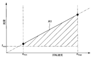
- the entire amount of hydraulic fluid discharged from the pump is circulated through the diverter valve a4 with the hydraulic pressure supplied to the steering. Will be. That is, when the cargo handling operation is not performed, the amount of hydraulic fluid corresponding to the area shown by the oblique lines in FIG. 5 flows unnecessarily through the diversion valve a4, and the power loss accompanying the pressure loss increases. That is, energy is wasted.
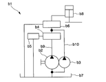
- a hydraulic circuit b1 having the following is considered.
- the hydraulic circuit b1 preferentially supplies the first hydraulic pump b2 and the second hydraulic pump b3, which are hydraulic supply sources, and the hydraulic fluid from the hydraulic pumps b2 and b3 to the steering b5.
- a flow dividing valve b4 for supplying surplus hydraulic fluid to the cargo handling actuator b8, a flow rate adjusting valve b6 provided between the flow dividing valve b4 and the cargo handling actuator b8, and a tank for storing the hydraulic fluid a main passage b9 that connects the first hydraulic pump b2, the flow dividing valve b4 and the flow rate adjusting valve b6 to the cargo handling actuator b8, the tank b7 of the main passage b9, and the first passage b9.
- a sub-passage b10 that branches from the fluid pressure pump b2 and passes through the second fluid pressure pump b3 and joins the main passage b9 again between the flow dividing valve b4 and the flow rate control valve b6 is provided.
- the present invention pays attention to the above points, and in a hydraulic circuit used for an industrial vehicle such as a forklift equipped with a cargo handling device, particularly a cargo handling vehicle, the power loss accompanying the pressure loss when the cargo handling operation is not performed is greatly reduced.
- the purpose is to plan.
- the hydraulic circuit according to the present invention has a configuration as described below. That is, the hydraulic circuit according to the present invention supplies a plurality of hydraulic pumps, which are hydraulic supply sources, and supplies hydraulic fluid from these hydraulic pumps preferentially to the steering and supplies surplus hydraulic fluid to the cargo handling actuator. And a flow control valve provided between the flow dividing valve and the cargo handling actuator, wherein the plurality of hydraulic pumps include one main pump and at least one hydraulic pump.
- Two sub-pumps and further provided when the discharge flow rate of the main pump is less than a predetermined discharge flow rate provided between the sub-pump and the diversion valve, or when the rotation speed of the main pump is lower than the predetermined rotation rate
- a switching valve that takes a second state that guides the hydraulic fluid from the sub-pump to a bypass passage that joins downstream of the diverter valve and upstream of the flow regulating valve. Yes.
- the cargo handling vehicle according to the present invention includes the hydraulic circuit described in the previous stage.
- the rotation speed of the main pump which can ensure the predetermined flow volume of the hydraulic fluid required for steering only by the hydraulic fluid from the main pump is set to the predetermined rotation speed, and the discharge flow rate of the main pump is When the flow rate is lower than the predetermined discharge flow rate or when the rotation speed of the main pump is lower than the predetermined rotation speed, the switching valve is set to the first state, so that the hydraulic pump that is not connected to the bypass passage, that is, the main pump Even if the volume is reduced, the flow rate of the hydraulic fluid supplied to the steering can be secured.
- the switching valve is set to the second state, thereby diverting the flow compared to the conventional one.
- the amount of hydraulic fluid that passes through the valve can be greatly reduced, and therefore, the power loss accompanying the pressure loss when the cargo handling operation is not performed can be greatly reduced.
- ADVANTAGE OF THE INVENTION in industrial vehicles, such as a forklift provided with a cargo handling apparatus, especially the hydraulic circuit used for a cargo handling vehicle, it can aim at the significant reduction of the power loss accompanying the pressure loss when not performing cargo handling work. .
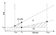
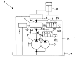
- the circuit diagram which shows the hydraulic circuit which concerns on one Embodiment of this invention The figure which shows the relationship between the rotational speed of the hydraulic pump which concerns on the embodiment, and the flow volume of the hydraulic fluid which shows the shunt valve of a hydraulic circuit.
- the circuit diagram which shows the hydraulic circuit which concerns on other embodiment of this invention The circuit diagram which shows the conventional hydraulic circuit.
- the hydraulic circuit 1 of the present embodiment is mounted on a cargo handling vehicle.
- two hydraulic pumps that are hydraulic supply sources, that is, a main pump 2 and a sub pump 3, and these liquids
- a main flow rate control valve 6 provided between the main pump 2, the flow dividing valve 4 and the flow rate adjustment valve 6 to the cargo handling actuator 8 from a tank 7 for storing hydraulic fluid.
- the main pump 2 and the diversion valve of the main passage 9 branch from the passage 9 and between the tank 7 of the main passage 9 and the main pump 2 and pass through the sub pump 3. Between the first sub-passage 10 that joins the main passage 9 again, and between the sub-pump 3 and the diversion valve 4 in the first sub-passage 10, and the diversion valve 4 in the main passage 9. A second sub-passage 11 that joins the main passage 9 with the flow rate adjusting valve 6 and a portion where the second sub-passage 11 branches from the first sub-passage 10 are provided in the main pump 2.
- a switching valve 12 which takes a second state for guiding the hydraulic fluid from the sub pump 3 to the second sub passage 11.
- the second sub-passage 11 is a bypass passage in the claims.
- the main pump 2 and the sub pump 3 are both connected to a vehicle driving engine or motor, which is a power source (not shown), and are fixed capacity pumps having a known configuration that rotate in conjunction with each other at the same rotational speed.
- the rotation speeds of the main pump 2 and the sub pump 3 are between the minimum rotation speed n min and the maximum rotation speed n max .
- the diversion valve 4 is used for a forklift or the like, and has a configuration similar to that known as a priority valve mechanism for supplying hydraulic fluid to the steering 5 and the cargo handling actuator 8. That is, the diversion valve 4 gives priority to the input port 4a serving as an inlet for the high-pressure hydraulic fluid discharged from the main pump 2 and the sub pump 3 and the hydraulic fluid necessary for the operation of the steering 5 and discharges it toward the steering 5. And a surplus flow output port 4c that discharges surplus hydraulic fluid toward the cargo handling actuator 8. The hydraulic fluid discharged from the surplus flow output port 4 c is guided to the cargo handling actuator 8 through the flow rate adjusting valve 6.
- the flow rate adjusting valve 6 has a function of adjusting the amount of hydraulic fluid guided to the cargo handling actuator 8 by changing the opening degree in response to an operation received by an operation lever (not shown).
- the switching valve 12 as described above, is provided between the diverter valve 4 and the subordinate fuel pump 3, when the rotational speed of the main pump 2 is below a predetermined rotational speed n 1, i.e. discharge from the main pump 2
- n 1 a predetermined rotational speed
- the hydraulic fluid from the sub pump 3 passes through the first sub passage 10 to the upstream side of the flow dividing valve 4.
- the hydraulic fluid from the sub-pump 3 passes through the second sub-passage 11 downstream of the flow dividing valve 4 and the flow rate is adjusted.
- the switching valve 12 includes a coil spring 12a that is an urging means for urging to take the first state and a urging force of the coil spring 12a when electric power is supplied. 2 is built in, and this solenoid 12b is connected to a control device (not shown) to be described later.
- This control device is formed by connecting a microcomputer system having a CPU, a storage device, and an input / output interface and a rotation speed sensor for detecting the rotation speed of the engine or motor, and outputs the rotation speed sensor.
- a microcomputer system having a CPU, a storage device, and an input / output interface and a rotation speed sensor for detecting the rotation speed of the engine or motor, and outputs the rotation speed sensor.
- the flow rate passing through the diversion valve 4 is as shown by the broken line D1 in FIG.
- the flow rate of the hydraulic fluid discharged from the main pump 2 exceeds the minimum flow rate necessary for operating the steering 5, that is, the predetermined discharge flow rate f min .
- the rotational speed in the region where the rotational speed is high as compared with the conventional hydraulic circuit a1 that uses only one hydraulic pump a2 described with reference to FIGS.
- the flow rate of the hydraulic fluid passing through 4 can be greatly reduced. More specifically, the amount of hydraulic fluid flowing through the shunt valve 4 unnecessarily when not performing loading operation is an amount corresponding to the region indicated by the shaded in FIG. 2, the rotational speed is the predetermined rotational speed n 1 2, that is, in a region where the flow rate of the hydraulic fluid discharged from the main pump 2 exceeds the predetermined discharge flow rate f min , a region X between the extended portion of the solid line D1 + D2 in FIG. 2 and the broken line D1 in FIG.
- the amount of hydraulic fluid that flows unnecessarily through the flow dividing valve 4 can be reduced by an amount corresponding to.
- the hydraulic fluid from the main pump 2 is used. Therefore, it is not necessary to secure the minimum flow rate f min necessary for operating the steering 5 alone, and the capacity of the main pump 2 can be reduced. Therefore, the flow rate of the working fluid that passes through the flow dividing valve 4 in the high rotation speed region Can be greatly reduced.
- the power loss due to the pressure loss at which the hydraulic fluid passes through the diverter valve 4 can be suppressed by significantly reducing the flow rate of the hydraulic fluid that passes through the diverter valve 4. And energy waste due to this power loss can be greatly reduced.
- FIG. The second switching valve 13 has a coil spring 13a which is a biasing means for biasing to take the first state, and a biasing force of the coil spring 13a when electric power is supplied.
- the solenoid 13b for making it a 2nd state is built in, and this solenoid is connected to the control apparatus mentioned later.
- This control device is formed by connecting a microcomputer system having a CPU, a storage device, and an input / output interface and a rotation speed sensor (not shown) that detects the rotation speed of the engine or motor, and performs a cargo handling operation. If it is not, the solenoid 13b is energized to control the switching valve 13 in the second state. Since the hydraulic circuit 1 shown in FIG. 3 has the same configuration as the hydraulic circuit 1 shown in FIGS. 1 and 2 in other points, the corresponding parts are denoted by the same names and symbols, and the details are as follows. Detailed explanations are omitted.
- the present invention may be applied to a hydraulic circuit having a plurality of sub pumps.
- a fixed displacement pump is used as the main pump and the sub pump, and attention is paid to the fact that the rotational speed and the discharge flow rate are substantially proportional.
- the switching valve is The first state is such that the hydraulic fluid from the sub pump is guided to the upstream side of the flow dividing valve, and the switching valve guides the hydraulic fluid from the sub pump to the bypass passage when the rotational speed exceeds a predetermined rotational speed.
- the power loss accompanying the pressure loss when the cargo handling operation is not performed is greatly reduced. be able to.
- Hydraulic circuit 2 ... Main pump (Hydraulic pump) 3. Sub pump (hydraulic pump) 4 ... Branch valve 6 ... Flow control valve 11 ... Bypass passage (second auxiliary passage) 12 ... Switching valve
Landscapes
- Engineering & Computer Science (AREA)
- Mechanical Engineering (AREA)
- Transportation (AREA)
- Combustion & Propulsion (AREA)
- Chemical & Material Sciences (AREA)
- Structural Engineering (AREA)
- General Engineering & Computer Science (AREA)
- Physics & Mathematics (AREA)
- Fluid Mechanics (AREA)
- Civil Engineering (AREA)
- Life Sciences & Earth Sciences (AREA)
- Geology (AREA)
- Fluid-Pressure Circuits (AREA)
- Forklifts And Lifting Vehicles (AREA)
Abstract
液圧供給源である複数の液圧ポンプと、これら液圧ポンプからの作動液を優先的にステアリングに供給するとともに余剰の作動液を荷役用アクチュエータに供給するための分流弁と、この分流弁と荷役用アクチュエータとの間に設けられる流量調整弁とを備えているものであって、前記複数の液圧ポンプとして、1つのメインポンプ及び少なくとも1つのサブポンプを有し、さらに、前記サブポンプと分流弁との間に設けられ前記メインポンプの吐出流量が所定吐出流量を下回る場合又は前記メインポンプの回転速度が所定回転速度を下回る場合には前記サブポンプからの作動液を分流弁の上流側に導く第1の状態をとるとともに前記メインポンプの吐出流量が所定吐出流量を上回る場合又は前記メインポンプの回転速度が所定回転速度を上回る場合には前記サブポンプからの作動液を分流弁の下流側かつ流量調整弁の上流側で合流するバイパス通路に導く第2の状態をとる切替弁を備えていることを特徴とする液圧回路を採用する。
Description
本発明は、主として荷役装置を備えたフォークリフト等の産業車両、特に荷役車両に用いられる液圧回路、及びこのような液圧回路を備えた荷役車両に関する。
従来より、荷役装置を備えたフォークリフト等の産業車両、特に荷役車両において、図4に示すように、液圧供給源である液圧ポンプa2と、液圧ポンプa2からの作動液を優先的にステアリングa5に供給するとともに余剰の作動液を荷役用アクチュエータa8に供給するための分流弁a4と、この分流弁a4と荷役用アクチュエータa8との間に設けられる流量調整弁a6と、作動液を貯蔵するためのタンクa7から前記液圧ポンプa2、前記分流弁a4及び前記流量調整弁a6を経て前記荷役用アクチュエータa8までを接続する通路a9とを備えた液圧回路a1が広く用いられている。
ところで、液圧ポンプからの作動液の流量は液圧ポンプの回転速度に比例する。また、荷役操作を行わない場合には、余剰の作動液は流量調整弁を経てタンクに戻される。このとき、液圧ポンプを1つのみ有する液圧回路を用いた場合、図5に示すように、ポンプから吐出される作動液の全量がステアリングに供給される液圧で分流弁a4内を流通することとなる。すなわち、荷役操作を行わない場合には、図5の斜線に示す領域に相当する量の作動液が不必要に分流弁a4内を流通し、圧力損失に伴う動力損失が大きくなる。すなわちエネルギーの無駄が大きくなる。
このような無駄を削減するための構成として、複数の液圧ポンプ、例えば図6に示すように第1の液圧ポンプb2と第2の液圧ポンプb3とを有し、以下のような構成を有する液圧回路b1が考えられている。この液圧回路b1は、液圧供給源である前記第1の液圧ポンプb2及び第2の液圧ポンプb3と、これら液圧ポンプb2、b3からの作動液を優先的にステアリングb5に供給するとともに余剰の作動液を荷役用アクチュエータb8に供給するための分流弁b4と、この分流弁b4と荷役用アクチュエータb8との間に設けられる流量調整弁b6と、作動液を貯蔵するためのタンクb7から前記第1の液圧ポンプb2、前記分流弁b4及び前記流量調整弁b6を経て前記荷役用アクチュエータb8までを接続する主通路b9と、前記主通路b9の前記タンクb7と前記第1の液圧ポンプb2との間から分岐し前記第2の液圧ポンプb3を経て前記分流弁b4と前記流量調節弁b6の間で再び主通路b9に合流する副通路b10とを具備する。このような液圧回路b1では、第1及び第2の液圧ポンプb2、b3が最低回転数nminで回転している場合にステアリングb5に最低限必要な量の作動液を供給できるようにすべく第1の液圧ポンプb2の容量を設定し、分流弁b4内を通過する液量を前段で述べた構成のものと比較して削減することはできる。
しかし、このような構成であっても、回転速度が高い場合には前記第1の液圧ポンプb2から吐出され分流弁b4を通過する作動液の量は大きく、前述した荷役操作を行わない場合には図5の斜線に示す領域に相当する量の作動液が不必要に分流弁b4内を流通し、圧力損失に伴う動力損失は依然として大きく、エネルギーの無駄が大きくなる。
本発明は以上の点に着目し、荷役装置を備えたフォークリフト等の産業車両、特に荷役車両に用いられる液圧回路において、荷役作業を行わない場合の圧力損失に伴う動力損失の大幅な削減を図ることを目的とする。
以上の課題を解決すべく、本発明に係る液圧回路は、以下に述べるような構成を有する。すなわち本発明に係る液圧回路は、液圧供給源である複数の液圧ポンプと、これら液圧ポンプからの作動液を優先的にステアリングに供給するとともに余剰の作動液を荷役用アクチュエータに供給するための分流弁と、この分流弁と荷役用アクチュエータとの間に設けられる流量調整弁とを備えている液圧回路であって、前記複数の液圧ポンプとして、1つのメインポンプ及び少なくとも1つのサブポンプを有し、さらに、前記サブポンプと分流弁との間に設けられ前記メインポンプの吐出流量が所定吐出流量を下回る場合又は前記メインポンプの回転速度が所定回転速度を下回る場合には前記サブポンプからの作動液を分流弁の上流側に導く第1の状態をとるとともに前記メインポンプの吐出流量が所定吐出流量を上回る場合又は前記メインポンプの回転速度が所定回転速度を上回る場合には前記サブポンプからの作動液を分流弁の下流側かつ流量調整弁の上流側で合流するバイパス通路に導く第2の状態をとる切替弁を備えている。
また、上述した課題を解決すべく、本発明に係る荷役車両は、前段に述べた液圧回路を備えている。
このようなものであれば、前記メインポンプからの作動液のみでステアリングに必要な作動液の所定流量を確保できるメインポンプの回転速度を前記所定回転速度に設定し、前記メインポンプの吐出流量が所定吐出流量を下回る場合又は前記メインポンプの回転速度が所定回転速度を下回る場合には切替弁を第1の状態とすることで、前記バイパス通路に接続していない液圧ポンプすなわち前記メインポンプの容量を小さくしても、ステアリングに供給する作動液の流量は確保できる。その一方で、前記メインポンプの容量を小さくできるので、荷役操作が行われず液圧ポンプの回転速度が高い場合には切替弁を第2の状態とすることで、従来のものと比較して分流弁を通過する作動液の量を大幅に削減でき、従って荷役作業を行わない場合の圧力損失に伴う動力損失の大幅な削減を図ることができる。
本発明によれば、荷役装置を備えたフォークリフト等の産業車両、特に荷役車両に用いられる液圧回路において、荷役作業を行わない場合の圧力損失に伴う動力損失の大幅な削減を図ることができる。
本発明の一実施形態を図1及び図2を参照しつつ以下に示す。
本実施形態の液圧回路1は、荷役車両に搭載されるものであり、図1に示すように、液圧供給源である2つの液圧ポンプ、すなわちメインポンプ2及びサブポンプ3と、これら液圧ポンプすなわちメインポンプ2及びサブポンプ3からの作動液を優先的にステアリング5に供給するとともに余剰の作動液を荷役用アクチュエータ8に供給するための分流弁4と、この分流弁4と荷役用アクチュエータ8との間に設けられる流量調整弁6と、作動液を貯蔵するためのタンク7から前記メインポンプ2、前記分流弁4及び前記流量調整弁6を経て前記荷役用アクチュエータ8までを接続する主通路9と、前記主通路9の前記タンク7と前記メインポンプ2との間から分岐し前記サブポンプ3を経て前記主通路9の前記メインポンプ2と前記分流弁4との間で再び主通路9に合流する第1の副通路10と、前記第1の副通路10の前記サブポンプ3と分流弁4との間から分岐し前記主通路9の前記分流弁4と前記流量調整弁6との間で前記主通路9に合流する第2の副通路11と、前記第2の副通路11が前記第1の副通路10と分岐する箇所に設けられメインポンプ2の回転速度が所定回転速度n1を下回る場合には前記サブポンプ3からの作動液を分流弁4の上流側に導く第1の状態をとるとともにメインポンプ2の回転速度が所定回転速度n1を上回る場合には前記サブポンプ3からの作動液を前記第2の副通路11に導く第2の状態をとる切替弁12とを備えている。ここで、前記第2の副通路11が、請求項中のバイパス通路である。
前記メインポンプ2及びサブポンプ3は、ともに図示しない動力源である車両の駆動用エンジン又はモータに接続されており、同一の回転速度で連動して回転する周知の構成の固定容量ポンプである。ここで、これらメインポンプ2及びサブポンプ3の回転速度は、最低回転速度nminと最高回転速度nmaxとの間である。
前記分流弁4は、フォークリフト等に用いられ、ステアリング5と、荷役用アクチュエータ8とに作動液を供給する優先弁機構として周知のものと同様の構成を有する。すなわち、この分流弁4は、前記メインポンプ2及びサブポンプ3から吐出された高圧作動液の導入口たる入力ポート4aと、ステアリング5の作動に必要な作動液を優先してステアリング5に向けて吐出する優先流出力口4bと、余剰の作動液を荷役用アクチュエータ8に向けて吐出する余剰流出力口4cとを具備する。前記余剰流出力口4cから吐出された作動液は、前記流量調整弁6を経て荷役用アクチュエータ8に導かれる。
前記流量調整弁6は、図示しない操作レバーが受け付けた操作を受けて開度を変更することにより、荷役用アクチュエータ8に導かれる作動液の量を調節する機能を有する。
そして、前記切替弁12は、上述したように、前記サブポンプ3と分流弁4との間に設けられ、メインポンプ2の回転速度が所定回転速度n1を下回る場合、すなわちメインポンプ2からの吐出流量がステアリング5を作動させるために必要な最低限の流量である所定吐出流量fminを下回る場合には前記サブポンプ3からの作動液を第1の副通路10を経て分流弁4の上流側に導く第1の状態をとり、メインポンプ2の回転速度が所定回転速度n1を上回る場合には前記サブポンプ3からの作動液を第2の副通路11を経て分流弁4の下流側かつ流量調整弁6の上流側に導く第2の状態をとる。ここで、メインポンプ2からの作動液の吐出流量は、メインポンプ2の回転速度に略比例する。すなわち、前記所定回転速度n1では、メインポンプ2から吐出される作動液の流量が、前記所定吐出流量fminと略等しくなる。そして、この切替弁12は、第1の状態をとるように付勢するための付勢手段であるコイルばね12aと、電力が供給された際に前記コイルばね12aの付勢力に抗して第2の状態とするためのソレノイド12bとを内蔵しており、このソレノイド12bは後述する図示しない制御装置に接続されている。この制御装置は、CPU、記憶装置、入出力インタフェースを備えたマイクロコンピュータシステムと、エンジン又はモータの回転速度を検知する回転数センサとを接続して形成したものであり、前記回転数センサの出力信号が示す回転速度が前記所定回転速度n1を上回った場合には前記ソレノイド12bに通電し、切替弁12を第2の状態とする制御を行う。
ここで、メインポンプ2の回転速度と分流弁4を通過する流量との関係について図2を参照しつつ述べると、回転速度が前記所定回転速度n1を下回る際には、上述したように切替弁12は第1の状態をとるので、メインポンプ2及びサブポンプ3から吐出される作動液はいずれも分流弁4を通過する。従って、分流弁4を通過する流量は図2の実線D1+D2に示すようなものとなる。一方、回転速度が前記所定回転速度n1を上回る際には、上述したように切替弁12は第2の状態をとるので、メインポンプ2から吐出される作動液のみが分流弁4を通過する。従って、分流弁4を通過する流量は図2の破線D1に示すようなものとなる。その際にメインポンプ2から吐出される作動液の流量はステアリング5を作動させるために必要な最低限の流量すなわち前記所定吐出流量fminを上回っている。
すなわち本実施形態によれば、図4及び図5を参照しつつ説明した1つの液圧ポンプa2のみを利用する従来の液圧回路a1と比較して、回転数が高い領域においては、分流弁4を通過する作動液の流量を大幅に削減できる。より具体的には、荷役操作を行わない場合に分流弁4を不必要に流通する作動液の量は図2の斜線に示す領域に相当する量であり、回転速度が前記所定回転速度n1を上回る領域すなわちメインポンプ2から吐出される作動液の流量が、前記所定吐出流量fminを上回る領域では、図2において前記図2の実線D1+D2の延長部分と前記破線D1との間の領域Xに相当する量だけ、分流弁4を不必要に流通する作動液の量を削減できる。また、図6及び図7を参照しつつ説明した従来の液圧回路1と比較しても、最低回転数nmin近傍ではメインポンプ2及びサブポンプ3を利用するので、メインポンプ2からの作動液のみでステアリング5を作動させるために必要な最低限の流量fminを確保する必要がなく、メインポンプ2の容量を小さくできることから、回転数が高い領域において分流弁4を通過する作動液の流量を大幅に削減できる。すなわち、従来の液圧回路1と比較して、分流弁4を通過する作動液の流量を大幅に削減することにより作動液が分流弁4を通過する圧力損失に伴う動力損失を抑制できる。そして、この動力損失によるエネルギーの無駄も大幅に削減できる。
なお、本発明は上述した実施例に限らない。
例えば、図3に示すように、バイパス通路すなわち第2の副流路11中に、サブポンプ3を通過した作動液をタンク通路14を経てタンク7に導く第1の状態とサブポンプ3を通過した作動液を流量調整弁6の上流側に導く第2の状態とをとることが可能な第2の切替弁13を設けてもよい。この第2の切替弁13は、第1の状態をとるように付勢するための付勢手段であるコイルばね13aと、電力が供給された際に前記コイルばね13aの付勢力に抗して第2の状態とするためのソレノイド13bとを内蔵しており、このソレノイドは後述する制御装置に接続されている。この制御装置は、CPU、記憶装置、入出力インタフェースを備えたマイクロコンピュータシステムと、エンジン又はモータの回転速度を検知する図示しない回転数センサとを接続して形成したものであり、荷役作業が行われている場合には前記ソレノイド13bに通電し、切替弁13を第2の状態とする制御を行う。なお、図3に示す液圧回路1は、その他の点では図1及び図2に示す液圧回路1と同様の構成を有するので、対応する箇所には同一の名称及び符号を付し、詳細な説明は省略している。
このような構成であれば、荷役作業が行われていない場合にはサブポンプ3を通過した作動液を無負荷でタンク7に導くことができるので、作動液が流量調整弁6を通過する圧力損失に伴う動力損失をも抑制できる。そして、この動力損失によるエネルギーの無駄をさらに削減できる。
また、複数のサブポンプを有する液圧回路に本発明を適用してもよい。
加えて、上述した実施形態では、メインポンプ及びサブポンプとして固定容量ポンプを利用し、回転速度と吐出流量とが略比例することに着目し、回転速度が所定回転速度を下回る場合に切替弁が前記サブポンプからの作動液を分流弁の上流側に導く第1の状態をとるようにしているとともに、回転速度が所定回転速度を上回る場合に切替弁が前記サブポンプからの作動液をバイパス通路に導く第2の状態をとるようにしているが、メインポンプからの作動液の吐出流量を流量センサ等の流量検知手段を用いて直接検知し、検知した作動液の吐出流量が所定吐出流量を下回る場合に切替弁が前記サブポンプからの作動液を分流弁の上流側に導く第1の状態をとるようにするとともに、検知した作動液の吐出流量が所定吐出流量を上回る場合に切替弁が前記サブポンプからの作動液をバイパス通路に導く第2の状態をとるようにする構成を採用してもよい。
その他、本発明の趣旨を損ねない範囲で種々に変更してよい。
本発明の構成を採用すれば、荷役装置を備えたフォークリフト等の産業車両、特に荷役車両に用いられる液圧回路において、荷役作業を行わない場合の圧力損失に伴う動力損失の大幅な削減を図ることができる。
1…液圧回路
2…メインポンプ(液圧ポンプ)
3…サブポンプ(液圧ポンプ)
4…分流弁
6…流量調整弁
11…バイパス通路(第2の副通路)
12…切替弁
2…メインポンプ(液圧ポンプ)
3…サブポンプ(液圧ポンプ)
4…分流弁
6…流量調整弁
11…バイパス通路(第2の副通路)
12…切替弁
Claims (2)
- 液圧供給源である複数の液圧ポンプと、これら液圧ポンプからの作動液を優先的にステアリングに供給するとともに余剰の作動液を荷役用アクチュエータに供給するための分流弁と、この分流弁と荷役用アクチュエータとの間に設けられる流量調整弁とを備えている液圧回路であって、前記複数の液圧ポンプとして、1つのメインポンプ及び少なくとも1つのサブポンプを有し、さらに、前記サブポンプと分流弁との間に設けられ前記メインポンプの吐出流量が所定吐出流量を下回る場合又は前記メインポンプの回転速度が所定回転速度を下回る場合には前記サブポンプからの作動液を分流弁の上流側に導く第1の状態をとるとともに前記メインポンプの吐出流量が所定吐出流量を上回る場合又は前記メインポンプの回転速度が所定回転速度を上回る場合には前記サブポンプからの作動液を分流弁の下流側かつ流量調整弁の上流側で合流するバイパス通路に導く第2の状態をとる切替弁を備えていることを特徴とする液圧回路。
- 液圧供給源である複数の液圧ポンプと、これら液圧ポンプからの作動液を優先的にステアリングに供給するとともに余剰の作動液を荷役用アクチュエータに供給するための分流弁と、この分流弁と荷役用アクチュエータとの間に設けられる流量調整弁とを備えている液圧回路を搭載した荷役車両であって、前記複数の液圧ポンプとして、1つのメインポンプ及び少なくとも1つのサブポンプを有し、さらに、前記サブポンプと分流弁との間に設けられ前記メインポンプの吐出流量が所定吐出流量を下回る場合又は前記メインポンプの回転速度が所定回転速度を下回る場合には前記サブポンプからの作動液を分流弁の上流側に導く第1の状態をとるとともに前記メインポンプの吐出流量が所定吐出流量を上回る場合又は前記メインポンプの回転速度が所定回転速度を上回る場合には前記サブポンプからの作動液を分流弁の下流側かつ流量調整弁の上流側で合流するバイパス通路に導く第2の状態をとる切替弁を備えていることを特徴とする荷役車両。
Priority Applications (4)
| Application Number | Priority Date | Filing Date | Title |
|---|---|---|---|
| CN201280077751.2A CN104870832B (zh) | 2012-12-19 | 2012-12-19 | 液压回路以及装卸车辆 |
| PCT/JP2012/082913 WO2014097423A1 (ja) | 2012-12-19 | 2012-12-19 | 液圧回路及び荷役車両 |
| JP2014552813A JP5896041B2 (ja) | 2012-12-19 | 2012-12-19 | 液圧回路及び荷役車両 |
| TW102144513A TWI486529B (zh) | 2012-12-19 | 2013-12-05 | 液壓迴路以及裝卸車輛 |
Applications Claiming Priority (1)
| Application Number | Priority Date | Filing Date | Title |
|---|---|---|---|
| PCT/JP2012/082913 WO2014097423A1 (ja) | 2012-12-19 | 2012-12-19 | 液圧回路及び荷役車両 |
Publications (1)
| Publication Number | Publication Date |
|---|---|
| WO2014097423A1 true WO2014097423A1 (ja) | 2014-06-26 |
Family
ID=50977806
Family Applications (1)
| Application Number | Title | Priority Date | Filing Date |
|---|---|---|---|
| PCT/JP2012/082913 Ceased WO2014097423A1 (ja) | 2012-12-19 | 2012-12-19 | 液圧回路及び荷役車両 |
Country Status (4)
| Country | Link |
|---|---|
| JP (1) | JP5896041B2 (ja) |
| CN (1) | CN104870832B (ja) |
| TW (1) | TWI486529B (ja) |
| WO (1) | WO2014097423A1 (ja) |
Cited By (4)
| Publication number | Priority date | Publication date | Assignee | Title |
|---|---|---|---|---|
| CN106762928A (zh) * | 2017-01-17 | 2017-05-31 | 徐工集团工程机械有限公司 | 车辆液压系统及具有其的工程车辆 |
| JP2020011544A (ja) * | 2018-07-13 | 2020-01-23 | 株式会社豊田自動織機 | 産業車両 |
| WO2021110866A1 (de) * | 2019-12-03 | 2021-06-10 | Liebherr-Werk Bischofshofen Gmbh | Hydrauliksystem mit einem weichenventilblock für eine hydraulisch betätigbare arbeitsmaschine |
| WO2021110853A1 (de) * | 2019-12-03 | 2021-06-10 | Liebherr-Werk Bischofshofen Gmbh | Weichenventilbock für eine hydraulisch betätigbare arbeitsmaschine |
Families Citing this family (5)
| Publication number | Priority date | Publication date | Assignee | Title |
|---|---|---|---|---|
| JP6577336B2 (ja) * | 2015-11-05 | 2019-09-18 | 株式会社豊田自動織機 | 産業車両 |
| EP4497722A3 (en) * | 2017-01-17 | 2025-04-23 | The Raymond Corporation | Variable hydraulic pressure relief systems and methods for a material handling vehicle |
| US10611401B2 (en) * | 2017-05-16 | 2020-04-07 | Zf Active Safety And Electronics U.S. Llc | Power steering apparatus |
| JP7428111B2 (ja) * | 2020-10-20 | 2024-02-06 | 株式会社ジェイテクト | 操舵装置 |
| CN114506799B (zh) * | 2022-04-20 | 2022-07-08 | 杭叉集团股份有限公司 | 一种叉车门架联合动作控制方法及控制系统 |
Citations (5)
| Publication number | Priority date | Publication date | Assignee | Title |
|---|---|---|---|---|
| JPS5126295U (ja) * | 1974-08-14 | 1976-02-26 | ||
| JPS57114761A (en) * | 1981-01-07 | 1982-07-16 | Komatsu Ltd | Steering demand valve |
| JPS60175805A (ja) * | 1984-02-20 | 1985-09-10 | Komatsu Ltd | ステアリング・作業機用油圧回路 |
| JPH01128466U (ja) * | 1988-02-26 | 1989-09-01 | ||
| JPH11181842A (ja) * | 1997-12-18 | 1999-07-06 | Komatsu Ltd | ホイールローダの油圧ポンプ回路 |
Family Cites Families (13)
| Publication number | Priority date | Publication date | Assignee | Title |
|---|---|---|---|---|
| JP2716875B2 (ja) * | 1991-04-01 | 1998-02-18 | 三菱重工業株式会社 | フォークリフトの作業機シリンダ供給流量制御装置 |
| JP2624039B2 (ja) * | 1991-07-31 | 1997-06-25 | 神鋼電機株式会社 | 荷役制御装置 |
| JPH0527423U (ja) * | 1991-09-13 | 1993-04-09 | 株式会社小松製作所 | クラツチ作動優先の変速機油圧回路 |
| JPH1160189A (ja) * | 1997-08-25 | 1999-03-02 | Komatsu Forklift Co Ltd | 産業車両用油圧回路 |
| JP2004150115A (ja) * | 2002-10-30 | 2004-05-27 | Komatsu Ltd | 油圧制御装置 |
| CN100451353C (zh) * | 2003-11-14 | 2009-01-14 | 株式会社小松制作所 | 建设机械的油压控制装置 |
| SE527434C8 (sv) * | 2004-07-28 | 2006-03-28 | Volvo Constr Equip Holding Se | Hydraulisksystem och arbetsmaskin innefattande ett sådant system |
| JP4389912B2 (ja) * | 2006-09-12 | 2009-12-24 | 日産自動車株式会社 | 産業車両の油圧制御装置 |
| EP2253854B1 (en) * | 2008-02-20 | 2014-09-10 | Komatsu, Ltd. | Oil pressure system and valve assembly used for oil pressure system |
| JP5113129B2 (ja) * | 2008-09-01 | 2013-01-09 | 日産フォークリフト株式会社 | 産業車両の油圧回路装置 |
| CN201545673U (zh) * | 2009-11-19 | 2010-08-11 | 浙江杭叉工程机械集团股份有限公司 | 叉车用液压系统 |
| JP5763317B2 (ja) * | 2010-09-14 | 2015-08-12 | ニチユ三菱フォークリフト株式会社 | 産業車両 |
| CN201962040U (zh) * | 2011-02-21 | 2011-09-07 | 安徽合力股份有限公司 | 带优先和卸荷功能的叉车液压系统 |
-
2012
- 2012-12-19 WO PCT/JP2012/082913 patent/WO2014097423A1/ja not_active Ceased
- 2012-12-19 CN CN201280077751.2A patent/CN104870832B/zh active Active
- 2012-12-19 JP JP2014552813A patent/JP5896041B2/ja active Active
-
2013
- 2013-12-05 TW TW102144513A patent/TWI486529B/zh not_active IP Right Cessation
Patent Citations (5)
| Publication number | Priority date | Publication date | Assignee | Title |
|---|---|---|---|---|
| JPS5126295U (ja) * | 1974-08-14 | 1976-02-26 | ||
| JPS57114761A (en) * | 1981-01-07 | 1982-07-16 | Komatsu Ltd | Steering demand valve |
| JPS60175805A (ja) * | 1984-02-20 | 1985-09-10 | Komatsu Ltd | ステアリング・作業機用油圧回路 |
| JPH01128466U (ja) * | 1988-02-26 | 1989-09-01 | ||
| JPH11181842A (ja) * | 1997-12-18 | 1999-07-06 | Komatsu Ltd | ホイールローダの油圧ポンプ回路 |
Cited By (8)
| Publication number | Priority date | Publication date | Assignee | Title |
|---|---|---|---|---|
| CN106762928A (zh) * | 2017-01-17 | 2017-05-31 | 徐工集团工程机械有限公司 | 车辆液压系统及具有其的工程车辆 |
| JP2020011544A (ja) * | 2018-07-13 | 2020-01-23 | 株式会社豊田自動織機 | 産業車両 |
| JP7024637B2 (ja) | 2018-07-13 | 2022-02-24 | 株式会社豊田自動織機 | 産業車両 |
| WO2021110866A1 (de) * | 2019-12-03 | 2021-06-10 | Liebherr-Werk Bischofshofen Gmbh | Hydrauliksystem mit einem weichenventilblock für eine hydraulisch betätigbare arbeitsmaschine |
| WO2021110853A1 (de) * | 2019-12-03 | 2021-06-10 | Liebherr-Werk Bischofshofen Gmbh | Weichenventilbock für eine hydraulisch betätigbare arbeitsmaschine |
| CN115003918A (zh) * | 2019-12-03 | 2022-09-02 | 利勃海尔比绍夫斯霍芬有限责任公司 | 用于液压驱动工作机器的开关阀块 |
| US12085097B2 (en) | 2019-12-03 | 2024-09-10 | Liebherr-Werk Bischofshofen Gmbh | Switch valve block for a hydraulically actuatable working machine |
| US12247590B2 (en) | 2019-12-03 | 2025-03-11 | Liebherr-Werk Bischofshofen Gmbh | Hydraulic system with a switch valve block for a hydraulically actuatable working machine |
Also Published As
| Publication number | Publication date |
|---|---|
| JP5896041B2 (ja) | 2016-03-30 |
| CN104870832B (zh) | 2016-11-23 |
| JPWO2014097423A1 (ja) | 2017-01-12 |
| TWI486529B (zh) | 2015-06-01 |
| TW201425740A (zh) | 2014-07-01 |
| CN104870832A (zh) | 2015-08-26 |
Similar Documents
| Publication | Publication Date | Title |
|---|---|---|
| JP5896041B2 (ja) | 液圧回路及び荷役車両 | |
| JP5763317B2 (ja) | 産業車両 | |
| US9181070B2 (en) | Hydraulic driving apparatus for working machine | |
| US9037356B2 (en) | Control device for hybrid construction machine | |
| US8807155B2 (en) | Control device for hybrid construction machine | |
| US20140325975A1 (en) | Swing relief energy regeneration apparatus of an excavator | |
| JPH09109908A (ja) | 産業用車両の油圧操向システム | |
| US20150152900A1 (en) | Control system for construction machine | |
| US20140130488A1 (en) | Hydraulic drive apparatus for work machine | |
| WO2014073497A1 (ja) | ハイブリッド建設機械の制御システム | |
| JP2010169204A (ja) | 油圧作業機の油圧回路 | |
| KR20130143585A (ko) | 건설기계의 유압펌프 제어시스템 | |
| CN101473138B (zh) | 液压驱动装置 | |
| CN102878126B (zh) | 静液压驱动系统 | |
| JP5350320B2 (ja) | 建設機械の制御装置 | |
| JP5118844B2 (ja) | 消費器を制御するための制御弁装置 | |
| JP2017125537A (ja) | ハイブリッド作業機の制御システム | |
| JP5164883B2 (ja) | 油圧制御システム | |
| JP6043157B2 (ja) | ハイブリッド建設機械の制御システム | |
| US9725885B2 (en) | Hydraulic construction machinery | |
| JP2006321267A (ja) | 産業車両の油圧制御装置 | |
| JP5219880B2 (ja) | 油圧制御システム | |
| KR200454928Y1 (ko) | 지게차의 핸들 조작성 향상을 위한 유압 제어 장치 | |
| JP2008018846A (ja) | 産業車両の油圧制御装置 | |
| WO2018168277A1 (ja) | クレーンの油圧回路 |
Legal Events
| Date | Code | Title | Description |
|---|---|---|---|
| 121 | Ep: the epo has been informed by wipo that ep was designated in this application |
Ref document number: 12890422 Country of ref document: EP Kind code of ref document: A1 |
|
| ENP | Entry into the national phase |
Ref document number: 2014552813 Country of ref document: JP Kind code of ref document: A |
|
| NENP | Non-entry into the national phase |
Ref country code: DE |
|
| 122 | Ep: pct application non-entry in european phase |
Ref document number: 12890422 Country of ref document: EP Kind code of ref document: A1 |