WO2014097384A1 - 発光装置 - Google Patents
発光装置 Download PDFInfo
- Publication number
- WO2014097384A1 WO2014097384A1 PCT/JP2012/082768 JP2012082768W WO2014097384A1 WO 2014097384 A1 WO2014097384 A1 WO 2014097384A1 JP 2012082768 W JP2012082768 W JP 2012082768W WO 2014097384 A1 WO2014097384 A1 WO 2014097384A1
- Authority
- WO
- WIPO (PCT)
- Prior art keywords
- electrode
- light emitting
- light
- emitting device
- layer
- Prior art date
Links
- 239000010410 layer Substances 0.000 claims abstract description 112
- 239000002346 layers by function Substances 0.000 claims abstract description 50
- 239000000758 substrate Substances 0.000 claims abstract description 48
- 238000005192 partition Methods 0.000 claims description 38
- 238000009413 insulation Methods 0.000 abstract 2
- 239000004020 conductor Substances 0.000 description 18
- 238000000605 extraction Methods 0.000 description 15
- 230000000694 effects Effects 0.000 description 9
- 239000007769 metal material Substances 0.000 description 9
- 239000010408 film Substances 0.000 description 7
- 238000002347 injection Methods 0.000 description 6
- 239000007924 injection Substances 0.000 description 6
- 239000002184 metal Substances 0.000 description 5
- 229910052751 metal Inorganic materials 0.000 description 5
- 238000004519 manufacturing process Methods 0.000 description 4
- 238000000151 deposition Methods 0.000 description 3
- 238000005401 electroluminescence Methods 0.000 description 3
- 230000017525 heat dissipation Effects 0.000 description 3
- 238000003780 insertion Methods 0.000 description 3
- 230000037431 insertion Effects 0.000 description 3
- 239000011810 insulating material Substances 0.000 description 3
- 229910044991 metal oxide Inorganic materials 0.000 description 3
- 150000004706 metal oxides Chemical class 0.000 description 3
- 238000000034 method Methods 0.000 description 3
- 239000011368 organic material Substances 0.000 description 3
- 230000005540 biological transmission Effects 0.000 description 2
- 239000003086 colorant Substances 0.000 description 2
- 239000010949 copper Substances 0.000 description 2
- 238000010586 diagram Methods 0.000 description 2
- 230000005525 hole transport Effects 0.000 description 2
- 239000000463 material Substances 0.000 description 2
- 238000004544 sputter deposition Methods 0.000 description 2
- RYGMFSIKBFXOCR-UHFFFAOYSA-N Copper Chemical compound [Cu] RYGMFSIKBFXOCR-UHFFFAOYSA-N 0.000 description 1
- 229910001111 Fine metal Inorganic materials 0.000 description 1
- BQCADISMDOOEFD-UHFFFAOYSA-N Silver Chemical compound [Ag] BQCADISMDOOEFD-UHFFFAOYSA-N 0.000 description 1
- 229910045601 alloy Inorganic materials 0.000 description 1
- 239000000956 alloy Substances 0.000 description 1
- 230000002238 attenuated effect Effects 0.000 description 1
- 230000015572 biosynthetic process Effects 0.000 description 1
- 238000004891 communication Methods 0.000 description 1
- 150000001875 compounds Chemical class 0.000 description 1
- 229910052802 copper Inorganic materials 0.000 description 1
- 238000005530 etching Methods 0.000 description 1
- 238000001704 evaporation Methods 0.000 description 1
- 239000011521 glass Substances 0.000 description 1
- AMGQUBHHOARCQH-UHFFFAOYSA-N indium;oxotin Chemical compound [In].[Sn]=O AMGQUBHHOARCQH-UHFFFAOYSA-N 0.000 description 1
- 150000002736 metal compounds Chemical class 0.000 description 1
- 238000002156 mixing Methods 0.000 description 1
- 230000003287 optical effect Effects 0.000 description 1
- 150000002902 organometallic compounds Chemical class 0.000 description 1
- 238000013021 overheating Methods 0.000 description 1
- 238000000059 patterning Methods 0.000 description 1
- 230000002093 peripheral effect Effects 0.000 description 1
- 238000000206 photolithography Methods 0.000 description 1
- 238000002310 reflectometry Methods 0.000 description 1
- 239000011347 resin Substances 0.000 description 1
- 229920005989 resin Polymers 0.000 description 1
- 229910052709 silver Inorganic materials 0.000 description 1
- 239000004332 silver Substances 0.000 description 1
- 239000010409 thin film Substances 0.000 description 1
- YVTHLONGBIQYBO-UHFFFAOYSA-N zinc indium(3+) oxygen(2-) Chemical compound [O--].[Zn++].[In+3] YVTHLONGBIQYBO-UHFFFAOYSA-N 0.000 description 1
Images


Classifications
-
- H—ELECTRICITY
- H10—SEMICONDUCTOR DEVICES; ELECTRIC SOLID-STATE DEVICES NOT OTHERWISE PROVIDED FOR
- H10K—ORGANIC ELECTRIC SOLID-STATE DEVICES
- H10K59/00—Integrated devices, or assemblies of multiple devices, comprising at least one organic light-emitting element covered by group H10K50/00
- H10K59/80—Constructional details
- H10K59/805—Electrodes
- H10K59/8051—Anodes
- H10K59/80516—Anodes combined with auxiliary electrodes, e.g. ITO layer combined with metal lines
Definitions
- the present invention relates to a light emitting device.
- This light-emitting device has a pair of electrodes that sandwich a light-emitting layer, and at least one of the pair of electrodes is a light-transmitting electrode such as a transparent electrode (see, for example, Patent Document 1). .
- a transparent electrode and an auxiliary electrode facing the transparent electrode are arranged on the light extraction side with respect to the light emitting layer. This document describes that the resistance of the transparent electrode is reduced by connecting the auxiliary electrode and the transparent electrode via a columnar conductor.
- Patent Document 1 Since the conductor is arranged on the light extraction side with the light emitting layer as a reference, the light is attenuated by the presence of the conductor, resulting in a decrease in light extraction efficiency.
- An example of a problem to be solved by the present invention is to improve power transmission efficiency by inputting power with low resistance to the light emitting layer while suppressing a decrease in light extraction efficiency of the light emitting device.
- the invention according to claim 1 is a translucent substrate; A translucent first electrode disposed on one surface side of the translucent substrate; An organic functional layer including at least a light-emitting layer and disposed on the opposite side of the translucent substrate with respect to the first electrode; A second electrode disposed on the opposite side of the first electrode with respect to the organic functional layer; An insulating layer covering a surface of the second electrode opposite to the translucent substrate side; A third electrode disposed on a surface of the insulating layer opposite to the translucent substrate side; The third electrode and the third electrode while being insulated from the second electrode by passing through the insulating layer and passing through the non-forming region of the second electrode in the layer where the second electrode is formed A conductive portion electrically connecting the first electrode to each other; It is a light-emitting device provided with.
- FIG. 1 is a cross-sectional view of a light emitting device according to Example 1.
- FIG. 4 is a plan view for explaining an example of a planar arrangement of a part of the configuration of the light emitting device according to Example 1.
- FIG. It is sectional drawing which shows the 1st example of the layer structure of an organic functional layer.
- FIG. 7A and FIG. 7B are cross-sectional views illustrating a series of manufacturing steps of the light emitting device according to the first embodiment.
- FIG. 8A is a side view of the conductor constituting the conductive portion
- FIG. 8B is a plan view of the conductor.
- 6 is a cross-sectional view of a light emitting device according to Example 2.
- FIG. 6 is a cross-sectional view of a light emitting device according to Example 3.
- FIG. 1 is a cross-sectional view of a light emitting device according to an embodiment.
- This light-emitting device includes an organic EL (Electro Luminescence) element.
- This light emitting device can be used as a light source of a display, a lighting device, or an optical communication device, for example.
- the light-emitting device includes a light-transmitting substrate 110, a light-transmitting first electrode 130 disposed on one surface side of the light-transmitting substrate 110, and a light-transmitting light including at least a light-emitting layer as a reference.
- the organic functional layer 140 is provided on the side opposite to the conductive substrate 110.
- the light emitting device further covers the second electrode 150 disposed on the side opposite to the first electrode 130 with respect to the organic functional layer 140 and the surface of the second electrode 150 on the side opposite to the translucent substrate 110 side.
- An insulating layer 210 and a third electrode 220 disposed on the surface of the insulating layer 210 opposite to the light transmissive substrate 110 side are provided.
- the light emitting device is further insulated from the second electrode 150 by passing through the insulating layer 210 and passing through a region where the second electrode 150 is not formed in the layer where the second electrode 150 is formed.
- a conductive portion 190 is provided that electrically connects the third electrode 220 and the first electrode 130 to each other.
- the translucent substrate 110 is a plate-like member made of a translucent material such as glass or resin.
- the translucent substrate 110 may be a translucent film.
- the upper surface of the translucent substrate 110 that is, the surface of the translucent substrate 110 opposite to the organic functional layer 140 is a flat light extraction surface. This light extraction surface is in contact with air (refractive index 1) filling the light emission space.
- the light extraction film is affixed on the upper surface of the translucent board
- the first electrode 130 may be a transparent electrode made of a metal oxide conductor such as ITO (Indium Tin Oxide) or IZO (Indium Zinc Oxide). However, the first electrode 130 may be a metal thin film that is thin enough to transmit light.
- a metal oxide conductor such as ITO (Indium Tin Oxide) or IZO (Indium Zinc Oxide).
- the first electrode 130 may be a metal thin film that is thin enough to transmit light.
- the second electrode 150 is a reflective electrode made of a metal film such as Al.
- the second electrode 150 reflects light traveling from the organic functional layer 140 toward the second electrode 150 toward the translucent substrate 110.
- the light emitting layer of the organic functional layer 140 When a voltage is applied between the first electrode 130 and the second electrode 150, the light emitting layer of the organic functional layer 140 emits light.
- the first electrode 130, the translucent substrate 110, and the organic functional layer 140 all transmit at least part of the light emitted from the light emitting layer of the organic functional layer 140.
- a part of the light emitted from the light emitting layer is emitted (extracted) from the light extraction surface of the translucent substrate 110 to the outside of the light emitting device (that is, the light emission space).
- the conductive portion 190 is embedded in the insulating layer 210.
- the conductive part 190 is made of a metal material.
- the number of the conductive portions 190 may be one or plural.
- the number of the third electrodes 220 may be one or plural.
- the conductive portion 190 and the third electrode 220 may correspond one-to-one as shown in FIG. 1, and one third electrode 220 is electrically connected to the plurality of conductive portions 190. Also good.
- the conductive portion 190 vertically penetrates the insulating layer 210, the organic functional layer 140, and the second electrode 150.
- the conductive part 190 is insulated from the second electrode 150.
- an insertion hole 151 for inserting the conductive portion 190 into the second electrode 150 is formed in the second electrode 150 so that the conductive portion 190 is not in contact with the second electrode 150. ing.
- region (inside the insertion hole 151) of the 2nd electrode 150 in the layer in which the 2nd electrode 150 was formed is realizable. That is, a configuration in which the conductive portion 190 penetrates the second electrode 150 in a state where the conductive portion 190 is insulated from the second electrode 150 can be realized.
- the third electrode 220 can be made of a metal material such as copper, for example.
- the shape of the third electrode 220 is arbitrary.
- the cross section may be circular as shown in FIG. 1, or may be rectangular or other cross sectional shapes.
- the third electrodes 220 may be in non-contact with each other (separated from each other) or in contact with each other.
- one surface (the lower surface in FIG. 1) of the translucent substrate 110 and one surface (the upper surface in FIG. 1) of the first electrode 130 are in contact with each other.
- the other surface (lower surface in FIG. 1) of the first electrode 130 and one surface (upper surface in FIG. 1) of the organic functional layer 140 are in contact with each other.
- the other surface (lower surface in FIG. 1) of the organic functional layer 140 and one surface (upper surface in FIG. 1) of the second electrode 150 are in contact with each other.
- the other surface (lower surface in FIG. 1) of the second electrode 150 and one surface (upper surface in FIG. 1) of the insulating layer 210 are in contact with each other.
- another layer may exist between the translucent substrate 110 and the first electrode 130.
- another layer may exist between the first electrode 130 and the organic functional layer 140.
- another layer may exist between the organic functional layer 140 and the second electrode 150.
- another layer may exist between the second electrode 150 and the insulating layer 210.
- the light emitting device includes the translucent substrate 110, the translucent first electrode 130 disposed on one surface side of the translucent substrate 110, and at least the light emitting layer.
- An organic functional layer 140 disposed on the opposite side of the translucent substrate 110 with respect to one electrode 130; a second electrode 150 disposed on the opposite side of the first electrode 130 with respect to the organic functional layer 140;
- An insulating layer 210 covering a surface of the second electrode 150 opposite to the light transmissive substrate 110 side, a third electrode 220 disposed on the surface of the insulating layer 210 opposite to the light transmissive substrate 110 side,
- the third electrode 220 and the second electrode 150 are insulated from the second electrode 150 by passing through the insulating layer 210 and passing through a region where the second electrode 150 is not formed in the layer where the second electrode 150 is formed.
- the conductive portion 190 and the third electrode 220 can be disposed on the opposite side of the translucent substrate 110 with respect to the first electrode 130, they are closer to the translucent substrate 110 than the first electrode 130. It is possible to suppress a decrease in light extraction efficiency of the light emitting device as compared with the case where the light emitting device is disposed. Therefore, it is possible to input power with low resistance to the light emitting layer while suppressing a decrease in light extraction efficiency of the light emitting device, so that power transmission efficiency can be improved.
- the conductive portion 190 and the third electrode 220 are formed of a metal material, the light extraction efficiency of the light emitting device is not substantially affected.
- the conductive part 190 and the third electrode 220 are formed of a metal material, the resistance can be made lower than when they are formed of a transparent electrode made of a metal oxide conductor.
- the heat dissipation effect by the third electrode 220 can be expected. Further, since the third electrode 220 having good thermal conductivity is in contact with the insulating layer 210 and the surface area is increased as compared with the case of the insulating layer 210 alone, the heat released from the second electrode 150 to the insulating layer 210 is also increased. Heat can be suitably radiated. Thus, overheating during operation of the light emitting device can be suppressed.
- the part of the third electrode 220 serves as a terminal for taking out the first electrode 130. Therefore, it is not necessary to pull out the first electrode 130 or the bus electrode to the peripheral edge in a plan view of the light emitting device and input power to that portion. For this reason, the vicinity of the end face of the light emitting device can be an effective light emitting region.
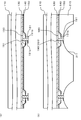
- FIG. 2 is a cross-sectional view of the light emitting device according to this example.
- FIG. 3 is a plan view for explaining an example of a planar arrangement of a part of the configuration of the light emitting device according to the present embodiment.
- the light-emitting device according to this example is different from the light-emitting device according to the above-described embodiment in the points described below, and is otherwise configured in the same manner as the light-emitting device according to the embodiment.
- the light emitting device includes a partition wall portion 180.
- the partition wall portion 180 is formed on one surface side (the lower surface side in FIG. 2) of the translucent substrate 110.
- the partition wall 180 divides the organic functional layer 140 into a plurality of regions (organic functional layers 140R, 140G, and 140B) in plan view.
- the electroconductive part 190 is arrange
- the first electrode 130 constitutes, for example, an anode.
- the plurality of first electrodes 130 each extend in a band shape in one direction in the planar direction (a direction from the front to the back in FIG. 2; hereinafter referred to as a Y direction).
- Adjacent first electrodes 130 are spaced apart from each other at regular intervals in the X direction orthogonal to the Y direction in the planar direction.
- a plurality of partition walls 180 made of an insulating film are formed on the first electrode 130. Each of the plurality of partition walls 180 extends in the Y direction.
- the partition wall portion 180 has, for example, a trapezoidal cross-sectional shape.
- a plurality of stripe-shaped openings each extending in the Y direction are formed in the insulating film forming the partition wall portion 180. That is, the interval between the adjacent partition walls 180 is an opening. Each of these openings reaches the first electrode 130, and the surface of each first electrode 130 is exposed at the bottom of the opening. An organic functional layer 140 is formed on the first electrode 130 in each opening.
- the organic functional layer 140 includes, for example, an organic functional layer 140R having a light emitting layer made of a fluorescent organic metal compound that emits red light and a fluorescent organic metal that emits green light.
- the organic functional layer 140G having a light emitting layer made of a compound or the like is divided into an organic functional layer 140B having a light emitting layer made of a fluorescent organometallic compound or the like that emits blue light.
- the organic functional layers 140R, 140G, and 140B are each formed in a stripe shape, and extend in the Y direction in parallel with each other.
- Organic functional layers 140R, 140G, and 140B that respectively emit red, green, and blue light are repeatedly arranged in the X direction (left and right direction in FIG. 3). From the surface of the translucent substrate 110 serving as a light extraction surface, red, green, and blue light are mixed at an arbitrary ratio to emit light that is recognized as a single emission color (for example, white).
- partition wall 180 divides the organic functional layer 140 into a plurality of regions (organic functional layers 140R, 140G, and 140B) and divides the first electrode 130 into a plurality of regions.
- the second electrode 150 covers the lower surface of the organic functional layer 140.
- the second electrode 150 is made of a metal such as Al or an alloy having a low work function and high reflectivity.
- the insulating layer 210 covers the lower surface of the second electrode 150 and the lower surface of the partition wall portion 180.
- the insulating layer 210 can be made of an insulating material such as an organic material, for example.
- the conductive portion 190 penetrates the partition wall portion 180 up and down. More specifically, for example, the conductive portion 190 is provided from the insulating layer 210 to the partition wall portion 180. One end portion (upper end portion) of the conductive portion 190 is in contact with the lower surface of the first electrode 130, and the other end portion (lower end portion) of the conductive portion 190 is exposed on the lower surface of the insulating layer 210.
- the third electrode 220 is in contact with the lower surface of the conductive portion 190.
- the conductive portion 190 has an inverted T-shaped cross section as shown in FIG. 2, but it may have a simple column shape.
- the third electrode 220 may be a fine metal wire with a circular cross section, but may have other shapes.
- the third electrode 220 is a thin metal wire having a circular cross section, for example, a groove 211 (concave portion) having an arc shape in cross section is formed on the lower surface of the insulating layer 210, and the third electrode 220 can be disposed in the groove 211. .
- the portion of the insulating layer 210 where the third electrode 220 is disposed is thinner than the other portions of the insulating layer 210.
- the third electrode 220 since the cross-sectional area of the third electrode 220 is large, an improvement in the heat dissipation effect of the light emitting device can be expected. In addition, since the vertical dimension of the conductive portion 190 can be shortened, the third electrode 220 can be easily and reliably connected to the first electrode 130 and the resistance of the conductive portion 190 can be suppressed. In addition, the third electrode 220 can be stably placed on the insulating layer 210 by making the shape of the groove 211 along the outer periphery of the third electrode 220. Note that the third electrode 220 may be bonded and fixed to the groove 211.
- the width of the third electrode 220 is larger than the width of the partition wall portion 180.
- the width of the third electrode 220 is larger than the width of the partition wall portion 180 in plan view.
- the third electrode 220 extends parallel to the partition wall portion 180 and is connected to the first electrode 130 via the conductive portion 190 at a plurality of locations in the longitudinal direction of the third electrode 220. May be. As a result, power can be input from the third electrode 220 to the first electrode 130 with lower resistance. For example, as shown in FIG. 3, a plurality of conductive parts 190 can be arranged along the partition wall part 180 at regular intervals.
- FIG. 4 is a diagram showing a first example of the layer structure of the organic functional layer 140.
- the organic functional layer 140 has a structure in which a hole injection layer 141, a hole transport layer 142, a light emitting layer 143, an electron transport layer 144, and an electron injection layer 145 are stacked in this order. That is, the organic functional layer 140 is an organic electroluminescence light emitting layer. Note that instead of the hole injection layer 141 and the hole transport layer 142, one layer having the functions of these two layers may be provided. Similarly, instead of the electron transport layer 144 and the electron injection layer 145, one layer having the functions of these two layers may be provided.
- the light emitting layer 143 is, for example, a layer that emits red light, a layer that emits blue light, a layer that emits yellow light, or a layer that emits green light.
- a region having a light emitting layer 143 that emits red light (light emitting layer 143 of the organic functional layer 140R) and a region having a light emitting layer 143 that emits green light (organic)
- the region having the light emitting layer 143) of the functional layer 140G and the light emitting layer 143 that emits blue light (the light emitting layer 143 of the organic functional layer 140B) is repeatedly provided. In this case, when each region emits light simultaneously, the light emitting device emits light in a single light emission color such as white.
- the light-emitting layer 143 may be configured to emit light in a single emission color such as white by mixing materials for emitting a plurality of colors. Further, a hole injection layer transport layer and an electron injection layer transport layer may be provided for each color to form a laminated structure thereof.
- FIG. 5 is a diagram showing a second example of the layer structure of the organic functional layer 140.
- the light emitting layer 143 of the organic functional layer 140 has a structure in which light emitting layers 143a, 143b, and 143c are stacked in this order.
- the light emitting layers 143a, 143b, and 143c emit light of different colors (for example, red, green, and blue).
- the light emitting layers 143a, 143b, and 143c emit light at the same time, so that the light emitting device emits light in a single emission color such as white.
- FIG. 6A, FIG. 6B, FIG. 7A, and FIG. 7B are cross-sectional views illustrating a series of manufacturing steps of the light emitting device according to the first embodiment.
- a light-transmitting conductive film made of a metal oxide conductor such as ITO or IZO is formed on the lower surface of the light-transmitting substrate 110 by sputtering or the like, and patterned by etching to form the first electrode 130.
- an insulating material is formed on the lower surface of the first electrode 130 and the lower surface of the translucent substrate 110, and the partition wall portion 180 is formed by patterning the insulating material by photolithography or the like.
- the partition wall portion 180 is patterned so that a through hole 181 that penetrates the partition wall portion 180 vertically and reaches the lower surface of the first electrode 130 is formed in the partition wall portion 180 (FIG. 6A).
- FIG. 8A is a side view of the conductor 191
- FIG. 8B is a plan view of the conductor 191.
- the conductor 191 has a columnar main body 191a and a disk-shaped terminal 191b formed at the lower end of the main body.
- the terminal portion 191b has a larger diameter than the main body portion 191a. For this reason, the side surface shape and the side cross-sectional shape are inverted T-shaped.
- the organic functional layer 140 is formed by depositing an organic material on the lower surface of the first electrode 130.
- the organic functional layer 140 can be formed by, for example, an inkjet method.
- the organic functional layer 140 may be formed before the conductor 191 is fixed to the partition wall portion 180.
- a second electrode 150 is formed on the lower surface of the organic functional layer 140 by depositing a metal material such as Al in a desired pattern by an evaporation method using a mask or a sputtering method (FIG. 7A). ).
- the second electrode 150 since the metal material is not deposited on the lower surface of the partition wall portion 180 and is covered with the terminal portion 191b, the second electrode 150 has an insertion hole 151 surrounding the body portion 191a of each conductor 191. It is formed.
- an insulating layer 210 is formed by depositing an organic material on the lower surface of the second electrode 150 and the exposed lower surface of the partition wall portion 180.
- the conductor 191 is embedded in the insulating layer 210.
- a groove 211 is formed in the insulating layer 210, and the terminal portion 191b is exposed on the lower surface of the insulating layer 210 (FIG. 7B).
- the third electrode 220 is disposed along the groove 211. Thereby, the light emitting device having the structure shown in FIG. 2 is obtained.
- the conductive portion 190 may be formed by forming 180 holes and embedding a metal material such as silver paste in the holes. In this case, the mold member may not be conductive.
- the light emitting device includes a partition wall portion 180 that is formed on one surface side of the translucent substrate 110 and divides the organic functional layer 140 into a plurality of regions in a plan view, and the conductive portion 190 has a plan view.
- the partition wall portion 180 is formed on one surface side of the translucent substrate 110 and divides the organic functional layer 140 into a plurality of regions in a plan view, and the conductive portion 190 has a plan view.
- the conductive portion 190 can be disposed in a region where the organic functional layer 140 is not disposed and does not contribute to light emission. Therefore, a decrease in light emission efficiency of the light emitting device can be suppressed.
- the third electrode 220 can have a lower resistance.
- the thickness of the portion of the insulating layer 210 where the third electrode 220 is disposed is thinner than the other portions of the insulating layer 210. Thereby, even when the third electrode 220 having a larger cross-sectional area is disposed, the vertical dimension (thickness) of the light emitting device can be suppressed. Furthermore, since the cross-sectional area of the third electrode 220 is large, an improvement in the heat dissipation effect of the light emitting device can be expected.
- FIG. 9 is a cross-sectional view of the light emitting device according to this example.
- the light emitting device according to the present example is different from the light emitting device according to Example 1 in the points described below, and is configured in the same manner as the light emitting device according to Example 1 in other points.
- the light emitting device overlaps with the partition wall 180 in a plan view, has a lower resistance than the first electrode 130, and is in contact with the first electrode 130, so that the first electrode 130 is electrically connected. It further has the 4th electrode (bus electrode 170) connected electrically.
- the fourth electrode and the third electrode 220 are electrically connected to each other at a plurality of locations by the plurality of conductive portions 190.
- the bus electrode 170 is made of a metal material such as Cu.
- the bus electrode 170 is embedded in the partition wall portion 180.
- the bus electrode 170 extends in the same direction as the direction in which the partition wall portion 180 extends.
- the bus electrode 170 is disposed inside the outline of the partition wall portion 180 in plan view.
- the bus electrode 170 is electrically connected to the third electrode 220 through the conductive portion 190 at a plurality of locations in the longitudinal direction.
- the light emitting device further includes the bus electrode 170 that overlaps the partition wall portion 180 in a plan view, has a lower resistance than the first electrode 130, and is in contact with the first electrode 130.
- the bus electrode 170 and the third electrode 220 are electrically connected to each other at a plurality of locations by the conductive portion 190. Therefore, even if any of the conductive parts 190 is disconnected for some reason, power can be supplied from the third electrode 220 to the bus electrode 170 via the other conductive part 190.
- FIG. 10 is a cross-sectional view of the light emitting device according to this example.
- the light emitting device according to this example is different from the light emitting device according to Example 2 in the points described below, and is configured in the same manner as the light emitting device according to Example 2 in other points.
- the light emitting device further includes a second conductive portion 230 embedded in the insulating layer 210.
- One end portion (the upper end portion in FIG. 10) of the second conductive portion 230 is in contact with the second electrode 150.
- the upper end surface of the second conductive part 230 is in contact with the lower surface of the second electrode 150.
- the other end portion (the lower end portion in FIG. 10) of the second conductive portion 230 is exposed on the surface (the lower surface in FIG. 10) on the opposite side of the insulating layer 210 from the translucent substrate 110 side.
- the second conductive portion 230 is formed in a columnar shape or a wall shape, for example. It is preferable that the plane cross-sectional area of the second conductive part 230 is larger than the plane cross-sectional area of the conductive part 190 (the plane cross-sectional area of the main body 191a). The second conductive part 230 is not in contact with the first electrode 130, the conductive part 190, and the third electrode 220. In plan view, the second conductive portion 230 is disposed away from the conductive portion 190.
- the light emitting device further includes the second conductive portion 230 embedded in the insulating layer 210, and one end of the second conductive portion 230 is in contact with the second electrode 150.
- the other end of the portion 230 is exposed on the surface of the insulating layer 210 opposite to the light transmissive substrate 110 side. Therefore, the other end portion of the second conductive portion 230 serves as a terminal for taking out the second electrode 150.
- the light emitting device has not only a terminal for taking out the first electrode 130 but also a terminal for taking out the second electrode 150 on the lower surface, so that the power to the first electrode 130 and the second electrode 150 can be reduced. Input can be performed from the lower surface side of the light emitting device.
Abstract
発光装置は、透光性基板(110)と、透光性基板(110)の一方の面側に配置された透光性の第1電極(130)と、少なくとも発光層を含み第1電極(130)を基準として透光性基板(110)とは反対側に配置された有機機能層(140)を備える。発光装置は、有機機能層(140)を基準として第1電極(130)とは反対側に配置された第2電極(150)と、第2電極(150)における透光性基板(110)側とは反対側の面を覆う絶縁層(210)と、絶縁層(210)における透光性基板(110)側とは反対側の面に配置された第3電極(220)を備える。発光装置は、第2電極(150)に対して絶縁された状態で第3電極(220)と第1電極(130)とを相互に電気的に接続している導電部(190)を備える。
Description
本発明は、発光装置に関する。
発光装置の1つに有機発光層を有する発光装置がある。この発光装置においては、有機発光層で発生した光のうち外部に放射される光の割合(光取り出し効率)を向上することが望まれている。この発光装置は、発光層を挟む一対の電極を有しており、一対の電極のうちの少なくとも何れか一方は、透明電極などの透光性の電極となっている(例えば特許文献1参照)。
特許文献1の発光装置においては、発光層を基準として光取り出し側に、透明電極と、透明電極に対して対向する補助電極と、が配置されている。同文献には、補助電極と透明電極とを柱状の導電体を介して接続することにより、透明電極の低抵抗化を図ることが記載されている。
本発明者は、特許文献1の技術には、以下に説明する問題があると考えた。
発光層を基準として光取り出し側に導電体が配置されているので、導電体の存在によって光が減衰してしまう結果、光取り出し効率が低下してしまう。
発光層を基準として光取り出し側に導電体が配置されているので、導電体の存在によって光が減衰してしまう結果、光取り出し効率が低下してしまう。
本発明が解決しようとする課題としては、発光装置の光取り出し効率の低下を抑制しつつ、発光層に対して低抵抗で電力を入力することによる電力伝送効率向上が一例として挙げられる。
請求項1に記載の発明は、透光性基板と、
前記透光性基板の一方の面側に配置された透光性の第1電極と、
少なくとも発光層を含み、前記第1電極を基準として前記透光性基板とは反対側に配置された有機機能層と、
前記有機機能層を基準として前記第1電極とは反対側に配置された第2電極と、
前記第2電極における前記透光性基板側とは反対側の面を覆う絶縁層と、
前記絶縁層における前記透光性基板側とは反対側の面に配置された第3電極と、
前記絶縁層を貫通するとともに、前記第2電極が形成された層における前記第2電極の非形成領域を通過することにより、前記第2電極に対して絶縁された状態で前記第3電極と前記第1電極とを相互に電気的に接続している導電部と、
を備える発光装置である。
上述した目的、およびその他の目的、特徴および利点は、以下に述べる好適な実施の形態、およびそれに付随する以下の図面によってさらに明らかになる。
以下、実施の形態について、図面を用いて説明する。尚、すべての図面において、同様の構成要素には同一の符号を付し、適宜説明を省略する。
図1は実施形態に係る発光装置の断面図である。この発光装置は、有機EL(Electro Luminescence)素子を含んで構成される。この発光装置は、例えばディスプレイ、照明装置、又は光通信装置の光源として用いることができる。
この発光装置は、透光性基板110と、透光性基板110の一方の面側に配置された透光性の第1電極130と、少なくとも発光層を含み第1電極130を基準として透光性基板110とは反対側に配置された有機機能層140を備える。発光装置は、更に、有機機能層140を基準として第1電極130とは反対側に配置された第2電極150と、第2電極150における透光性基板110側とは反対側の面を覆う絶縁層210と、絶縁層210における透光性基板110側とは反対側の面に配置された第3電極220と、を備える。発光装置は、更に、絶縁層210を貫通するとともに、第2電極150が形成された層における第2電極150の非形成領域を通過することにより、第2電極150に対して絶縁された状態で第3電極220と第1電極130とを相互に電気的に接続している導電部190を備える。
以下においては、説明を簡単にするため、発光装置の各構成要素の位置関係(上下関係等)が各図に示す関係であるものとして説明を行う。ただし、この説明における位置関係は、発光装置の使用時の位置関係とは無関係である。
透光性基板110は、ガラスや樹脂などの透光性を有する材料からなる板状部材である。なお、透光性基板110は、透光性のフィルムであっても良い。例えば、透光性基板110の上面、すなわち透光性基板110における有機機能層140とは反対側の面は、平坦な光取り出し面となっている。この光取り出し面は、光放出空間を充たす空気(屈折率1)と接している。なお、透光性基板110の上面には、光取り出しフィルムが貼り付けられており、この光取り出しフィルムの上面が、光取り出し面を構成していても良い。
第1電極130は、例えばITO(Indium Tin Oxide)やIZO(Indium Zinc Oxide)などの金属酸化物導電体からなる透明電極とすることができる。ただし、第1電極130は、光が透過する程度に薄い金属薄膜であっても良い。
第2電極150は、例えば、Alなどの金属膜からなる反射電極である。第2電極150は、有機機能層140から第2電極150側に向かう光を、透光性基板110側に向けて反射する。
第1電極130と第2電極150との間に電圧が印加されることにより、有機機能層140の発光層が発光する。第1電極130、透光性基板110、及び、有機機能層140は、いずれも、有機機能層140の発光層が発光した光の少なくとも一部を透過する。発光層が発光した光の一部は、透光性基板110の光取り出し面から、発光装置の外部(つまり上記光放出空間)に放射される(取り出される)。
導電部190は、絶縁層210に埋め込み形成されている。導電部190は、金属材料により構成されている。導電部190の数は、1つでも良いし、複数でも良い。第3電極220の数は、1つでも良いし、複数でも良い。導電部190と第3電極220は、図1に示すように1対1で対応していても良いし、1つの第3電極220が複数の導電部190に対して電気的に接続されていても良い。導電部190は、例えば、絶縁層210、有機機能層140および第2電極150を上下に貫通している。
ただし、導電部190は、第2電極150に対して絶縁されている。例えば、図1に示すように、導電部190が第2電極150に対して非接触となるように導電部190を第2電極150に挿通させるための挿通穴151が第2電極150に形成されている。これにより、第2電極150が形成された層における第2電極150の非形成領域(挿通孔151内)を導電部190が通過する構成を実現することができる。すなわち、導電部190が第2電極150に対して絶縁された状態で、導電部190が第2電極150を貫通した構成を実現できる。
第3電極220は、例えば銅などの金属材料により構成することができる。第3電極220の形状は任意である。図1に示すような断面円形であっても良いし、矩形或いはその他の断面形状であっても良い。また、発光装置が複数の第3電極220を備える場合、これら第3電極220が互いに非接触となっていても(互いに離間していても)良いし、互いに接触していても良い。
例えば、透光性基板110の一方の面(図1における下面)と第1電極130の一方の面(図1における上面)とが相互に接している。また、第1電極130の他方の面(図1における下面)と有機機能層140の一方の面(図1における上面)とが相互に接している。また、有機機能層140の他方の面(図1における下面)と第2電極150の一方の面(図1における上面)とが相互に接している。また、第2電極150の他方の面(図1における下面)と絶縁層210一方の面(図1における上面)とが相互に接している。ただし、透光性基板110と第1電極130との間には他の層が存在していても良い。同様に、第1電極130と有機機能層140との間には他の層が存在していても良い。同様に、有機機能層140と第2電極150との間には他の層が存在していても良い。同様に、第2電極150と絶縁層210との間には他の層が存在していても良い。
以上、本実施形態によれば、発光装置は、透光性基板110と、透光性基板110の一方の面側に配置された透光性の第1電極130と、少なくとも発光層を含み第1電極130を基準として透光性基板110とは反対側に配置された有機機能層140と、有機機能層140を基準として第1電極130とは反対側に配置された第2電極150と、第2電極150における透光性基板110側とは反対側の面を覆う絶縁層210と、絶縁層210における透光性基板110側とは反対側の面に配置された第3電極220と、絶縁層210を貫通するとともに、第2電極150が形成された層における第2電極150の非形成領域を通過することにより、第2電極150に対して絶縁された状態で第3電極220と第1電極130とを相互に電気的に接続している導電部190と、を備える。よって、第3電極220および導電部190によって、第1電極130に対して低抵抗(少ない電圧降下で)で電力を入力することができ、ひいては、第1電極130を介して発光層に対して電力を入力できる。また、導電部190および第3電極220は、第1電極130を基準として透光性基板110とは反対側に配置することができるため、これらが第1電極130よりも透光性基板110側に配置されている場合よりも、発光装置の光取り出し効率の低下を抑制できる。よって、発光装置の光取り出し効率の低下を抑制しつつ、発光層に対して低抵抗で電力を入力することができるので、電力伝送効率の向上が可能である。
また、導電部190および第3電極220は、それらを金属材料により形成しても、発光装置の光取り出し効率に実質的に影響を与えない。導電部190および第3電極220を金属材料により形成した場合、それらを金属酸化物導電体からなる透明電極により構成した場合よりも、低抵抗にできる。
また、第3電極220の一部分を絶縁層210における透光性基板110側とは反対側の面に露出させることにより、第3電極220による放熱効果を期待できる。さらに、熱伝導率のよい第3電極220が絶縁層210に接しており、しかも表面積が絶縁層210だけのときよりも増加するので、第2電極150から絶縁層210へ放出される熱についても好適に放熱できる。よって、発光装置の動作時の過熱を抑制することができる。
また、第3電極220の一部分を絶縁層210における透光性基板110側とは反対側の面に露出させることにより、第3電極220の当該一部分に電力を入力することができる。すなわち、第3電極220の当該一部分は、第1電極130の取り出し用の端子となる。よって、発光装置の平面視における周縁部に第1電極130又はバス電極を引き出して、その部分に電力を入力する必要がない。このため、発光装置の端面の近傍までを有効な発光領域にすることができる。
(実施例1)
図2は本実施例に係る発光装置の断面図である。図3は本実施例に係る発光装置の一部の構成の平面的な配置の例を説明するための平面図である。本実施例に係る発光装置は、以下に説明する点で、上記の実施形態に係る発光装置と相違し、その他の点では実施形態に係る発光装置と同様に構成されている。
図2は本実施例に係る発光装置の断面図である。図3は本実施例に係る発光装置の一部の構成の平面的な配置の例を説明するための平面図である。本実施例に係る発光装置は、以下に説明する点で、上記の実施形態に係る発光装置と相違し、その他の点では実施形態に係る発光装置と同様に構成されている。
本実施例に係る発光装置は、隔壁部180を備えている。隔壁部180は、透光性基板110の一方の面側(図2の下面側)に形成されている。隔壁部180は、有機機能層140を平面視において複数の領域(有機機能層140R、140G、140B)に分割している。そして、導電部190は、平面視において隔壁部180の外形線の内側に配置されている(図3参照)。
第1電極130は、例えば、陽極を構成する。複数の第1電極130が、それぞれ帯状に平面方向における一方向(図2の手前から奥に向かう方向:以下、Y方向という)に延在している。隣り合う第1電極130同士は、平面方向においてY方向に対して直交するX方向において一定間隔ずつ離間している。
第1電極130上には絶縁膜からなる複数の隔壁部180が形成されている。複数の隔壁部180は、それぞれY方向に延在している。隔壁部180は、例えば、台形状の断面形状を有している。
隔壁部180を形成する絶縁膜には、それぞれY方向に延在するストライプ状の開口部が複数形成されている。すなわち、隣り合う隔壁部180どうしの間隔が開口部となっている。これら開口部の各々は、第1電極130に達しており、開口部の底部において各第1電極130の表面が露出している。各開口部内において、第1電極130上には、有機機能層140が形成されている。
図3に示すように、有機機能層140は、隔壁部180によって、例えば、赤色発光を行う蛍光性有機金属化合物等からなる発光層を有する有機機能層140Rと、緑色発光を行う蛍光性有機金属化合物等からなる発光層を有する有機機能層140Gと、青色発光を行う蛍光性有機金属化合物等からなる発光層を有する有機機能層140Bと、に分割されている。有機機能層140R、140G、140Bは、それぞれストライプ状に形成され、互いに並列にY方向に延在している。赤、緑、青の光をそれぞれ発する有機機能層140R、140G、140Bが、X方向(図3の左右方向)に繰り返し配置されている。光取り出し面となる透光性基板110の表面からは、赤、緑、青の光が任意の割合で混色されて単一の発光色(例えば白色)として認識される光が放出される。
なお、隔壁部180は、有機機能層140を複数の領域(有機機能層140R、140G、140B)に分割しているとともに、第1電極130を複数の領域に分割している。
第2電極150は、有機機能層140の下面を覆っている。第2電極150は、仕事関数が低く且つ高反射率を有するAlなどの金属または合金等からなる。
絶縁層210は、第2電極150の下面と、隔壁部180の下面と、を覆っている。絶縁層210は、例えば、有機材料などの絶縁材料により構成することができる。
導電部190は、隔壁部180を上下に貫通している。より具体的には、例えば、導電部190は、絶縁層210内から隔壁部180内に亘って設けられている。導電部190の一端部(上端部)は、第1電極130の下面に接しており、導電部190の他端部(下端部)は、絶縁層210の下面に露出している。そして、導電部190の下面に対して第3電極220が接触している。導電部190は、例えば、図2に示すような逆T字形の断面形状のものであることが挙げられるが、単なる柱状のものであっても良い。
第3電極220は、断面円形の金属細線であることが挙げられるが、その他の形状のものであっても良い。
第3電極220を断面円形の金属細線とした場合、例えば、絶縁層210の下面に断面円弧状の溝211(凹部)を形成し、この溝211内に第3電極220を配置することができる。その結果、絶縁層210において第3電極220が配置されている部分の膜厚は、絶縁層210におけるその他の部分よりも膜厚が薄くなっている。これによって、より断面積が大きい第3電極220を配置しても、発光装置の上下寸法(厚み)を抑制することができる。更に、第3電極220の断面積が大きいことにより、発光装置の放熱効果の向上も期待できる。
また、導電部190の上下寸法を短くできるため、第3電極220を第1電極130に対して容易且つ確実に接続することができるとともに、導電部190の抵抗を抑制できる。また、溝211の形状を第3電極220の外周に沿う形状とすることにより、第3電極220を絶縁層210に対して安定的に設置することができる。なお、第3電極220は溝211に対して接着固定しても良い。
また、導電部190の上下寸法を短くできるため、第3電極220を第1電極130に対して容易且つ確実に接続することができるとともに、導電部190の抵抗を抑制できる。また、溝211の形状を第3電極220の外周に沿う形状とすることにより、第3電極220を絶縁層210に対して安定的に設置することができる。なお、第3電極220は溝211に対して接着固定しても良い。
隔壁部180の幅よりも第3電極220の幅の方が大きいことが好ましい。例えば、平面視において隔壁部180の幅よりも第3電極220の幅が大きい。このようにすることにより、第3電極220の断面積を十分に確保しやすくなり、第3電極220をより低抵抗にすることができる。
また、第3電極220は、隔壁部180に対して平行に延在しており、第3電極220の長手方向における複数箇所でそれぞれ導電部190を介して第1電極130に対して接続されていても良い。これにより、第3電極220から第1電極130に対してより低抵抗で電力を入力することができる。例えば、図3に示すように、隔壁部180に沿って複数の導電部190を一定間隔で配置することができる。
次に、有機機能層140の層構造の例について説明する。
図4は有機機能層140の層構造の第1例を示す図である。この有機機能層140は、正孔注入層141、正孔輸送層142、発光層143、電子輸送層144、及び電子注入層145をこの順に積層した構造を有している。すなわち有機機能層140は、有機エレクトロルミネッセンス発光層である。なお、正孔注入層141及び正孔輸送層142の代わりに、これら2つの層の機能を有する一つの層を設けてもよい。同様に、電子輸送層144及び電子注入層145の代わりに、これら2つの層の機能を有する一つの層を設けてもよい。
図4の例において、発光層143は、例えば赤色の光を発光する層、青色の光を発光する層、黄色の光を発光する層、又は緑色の光を発光する層である。図3に示すように、例えば、平面視において、赤色の光を発光する発光層143を有する領域(有機機能層140Rの発光層143)、緑色の光を発光する発光層143を有する領域(有機機能層140Gの発光層143)、及び青色の光を発光する発光層143(有機機能層140Bの発光層143)を有する領域が繰り返し設けられている。この場合、各領域を同時に発光させると、発光装置は白色等の単一の発光色で発光する。
なお、発光層143は、複数の色を発光するための材料を混ぜることにより、白色等の単一の発光色で発光するように構成されていても良い。
またそれぞれの色毎にホール注入層輸送層および電子注入層輸送層を設けて、それらの積層構造にしてもよい。
またそれぞれの色毎にホール注入層輸送層および電子注入層輸送層を設けて、それらの積層構造にしてもよい。
図5は有機機能層140の層構造の第2例を示す図である。この有機機能層140の発光層143は、発光層143a、143b、143cをこの順に積層した構成を有している。発光層143a、143b、143cは、互いに異なる色の光(例えば赤、緑、及び青)を発光する。そして発光層143a、143b、143cが同時に発光することにより、発光装置は白色等の単一の発光色で発光する。
次に、本実施例に係る発光装置の一連の製造工程を説明する。図6(a)、図6(b)、図7(a)および図7(b)は、実施例1に係る発光装置の一連の製造工程を示す断面図である。
先ず、透光性基板110の下面に、スパッタ法などによりITOやIZOなどの金属酸化物導電体からなる透光性の導電膜を成膜し、エッチングによりこれをパターニングして第1電極130を形成する。
次に、第1電極130の下面および透光性基板110の下面に絶縁材料を成膜し、これをフォトリソグラフィーなどによりパターニングすることにより隔壁部180を形成する。ここで、隔壁部180を上下に貫通し、上端が第1電極130の下面に達する貫通孔181が隔壁部180に形成されるように、隔壁部180のパターニングを行う(図6(a))。
次に、第1電極130の下面および透光性基板110の下面に絶縁材料を成膜し、これをフォトリソグラフィーなどによりパターニングすることにより隔壁部180を形成する。ここで、隔壁部180を上下に貫通し、上端が第1電極130の下面に達する貫通孔181が隔壁部180に形成されるように、隔壁部180のパターニングを行う(図6(a))。
次に、予め金属材料により形成した導電体191の一端部を貫通孔181に差し込んで、導電体191を隔壁部180に固定する(図6(b))。
ここで、図8(a)は導電体191の側面図、図8(b)は導電体191の平面図である。図8(a)および(b)に示すように、導電体191は、柱状の本体部191aと、本体部の下端に形成された円板状の端子部191bと、を有する。端子部191bは、本体部191aよりも大径である。このため、側面形状および側断面形状が逆T字状となっている。
ここで、図8(a)は導電体191の側面図、図8(b)は導電体191の平面図である。図8(a)および(b)に示すように、導電体191は、柱状の本体部191aと、本体部の下端に形成された円板状の端子部191bと、を有する。端子部191bは、本体部191aよりも大径である。このため、側面形状および側断面形状が逆T字状となっている。
次に、第1電極130の下面に有機材料を成膜することにより有機機能層140を形成する。有機機能層140の成膜は、例えば、インクジェット法などにより行うことができる。なお、有機機能層140の成膜は、導電体191を隔壁部180に固定する前に行っても良い。
次に、有機機能層140の下面に、マスクを用いた蒸着法又はスパッタリング法などにより、Al等の金属材料を所望のパターンに堆積させて、第2電極150を形成する(図7(a))。このとき、隔壁部180の下面において、端子部191bにより覆われた部分には金属材料が堆積しないため、第2電極150には、各導電体191の本体部191aの周囲を囲む挿通穴151が形成される。
次に、有機機能層140の下面に、マスクを用いた蒸着法又はスパッタリング法などにより、Al等の金属材料を所望のパターンに堆積させて、第2電極150を形成する(図7(a))。このとき、隔壁部180の下面において、端子部191bにより覆われた部分には金属材料が堆積しないため、第2電極150には、各導電体191の本体部191aの周囲を囲む挿通穴151が形成される。
次に、第2電極150の下面と、隔壁部180の露出した下面に有機材料を成膜することにより絶縁層210を形成する。ここで、導電体191を絶縁層210に埋め込む。次に、絶縁層210に溝211を形成し、端子部191bを絶縁層210の下面に露出させる(図7(b))。
次に、溝211に沿って第3電極220を配設する。これにより、図2に示す構造の発光装置が得られる。
なお、導電体191の代わりに、導電体191と同形状の型部材を用いて、図7(b)に示す工程までを行い、その後、この型部材を引き抜くことにより、絶縁層210から隔壁部180に亘る孔を形成し、この孔に銀ペーストなどの金属材料を埋め込むことによって導電部190を形成しても良い。この場合、型部材は、導電性でなくても良い。
本実施例によれば、上記の実施形態と同様の効果が得られる他に、以下の効果が得られる。
本実施例に係る発光装置は、透光性基板110の一方の面側に形成され、有機機能層140を平面視において複数の領域に分割する隔壁部180を備え、導電部190は、平面視において隔壁部180の外形線の内側に配置されている。よって、隔壁部180を有する発光装置において、有機機能層140が配置されず発光に寄与しない領域に、導電部190を配置することができる。よって、発光装置の発光効率の低下を抑制することができる。
隔壁部180の幅よりも第3電極220の幅の方が大きいので、第3電極220をより低抵抗にすることができる。
絶縁層210において第3電極220が配置されている部分の膜厚は、絶縁層210におけるその他の部分よりも膜厚が薄い。これによって、より断面積が大きい第3電極220を配置しても、発光装置の上下寸法(厚み)を抑制することができる。更に、第3電極220の断面積が大きいことにより、発光装置の放熱効果の向上も期待できる。
(実施例2)
図9は本実施例に係る発光装置の断面図である。本実施例に係る発光装置は、以下に説明する点で上記の実施例1に係る発光装置と相違し、その他の点では、実施例1に係る発光装置と同様に構成されている。
図9は本実施例に係る発光装置の断面図である。本実施例に係る発光装置は、以下に説明する点で上記の実施例1に係る発光装置と相違し、その他の点では、実施例1に係る発光装置と同様に構成されている。
本実施例の場合、発光装置は、平面視において隔壁部180と重なり、第1電極130よりも低抵抗で且つ第1電極130に対して接していることにより該第1電極130に対して電気的に接続されている第4電極(バス電極170)を更に有している。複数の導電部190によって、第4電極と第3電極220とが複数箇所において相互に電気的に接続されている。
バス電極170は、Cu等の金属材料からなる。バス電極170は、隔壁部180に埋め込まれている。バス電極170は、隔壁部180が延在する方向と同じ方向に延在している。例えば、バス電極170は、平面視において隔壁部180の外形線の内側に配置されている。バス電極170は、その長手方向における複数箇所でそれぞれ導電部190を介して第3電極220に対して電気的に接続されている。
本実施例によれば、上記の実施例1と同様の効果が得られる他に、以下の効果が得られる。
本実施例によれば、発光装置は、平面視において隔壁部180と重なり、第1電極130よりも低抵抗で且つ第1電極130に対して接しているバス電極170を更に有し、複数の導電部190によって、バス電極170と第3電極220とが複数箇所において相互に電気的に接続されている。よって、何らかの原因で何れかの導電部190が断線したとしても、他の導電部190を介して、第3電極220からバス電極170に対して電力を供給することができる。
本実施例によれば、発光装置は、平面視において隔壁部180と重なり、第1電極130よりも低抵抗で且つ第1電極130に対して接しているバス電極170を更に有し、複数の導電部190によって、バス電極170と第3電極220とが複数箇所において相互に電気的に接続されている。よって、何らかの原因で何れかの導電部190が断線したとしても、他の導電部190を介して、第3電極220からバス電極170に対して電力を供給することができる。
(実施例3)
図10は本実施例に係る発光装置の断面図である。本実施例に係る発光装置は、以下に説明する点で上記の実施例2に係る発光装置と相違し、その他の点では、実施例2に係る発光装置と同様に構成されている。
図10は本実施例に係る発光装置の断面図である。本実施例に係る発光装置は、以下に説明する点で上記の実施例2に係る発光装置と相違し、その他の点では、実施例2に係る発光装置と同様に構成されている。
本実施例の場合、発光装置は、絶縁層210に埋め込み形成された第2導電部230を更に備えている。第2導電部230の一端部(図10の上端部)が第2電極150に対して接触している。例えば、第2導電部230の上端面が第2電極150の下面に接触している。また、第2導電部230の他端部(図10の下端部)が絶縁層210における透光性基板110側とは反対側の面(図10の下面)に露出している。
第2導電部230は、例えば、柱状又は壁状に形成されている。第2導電部230の平断面積は、導電部190の平断面積(上記の本体部191aの平断面積)よりも大きいことが好ましい。第2導電部230は、第1電極130、導電部190および第3電極220に対して非接触となっている。平面視において、第2導電部230は、導電部190から離間して配置されている。
本実施例によれば、上記の実施例2と同様の効果が得られる他に、以下の効果が得られる。
本実施例によれば、発光装置は、絶縁層210に埋め込み形成された第2導電部230を更に備え、第2導電部230の一端部が第2電極150に対して接触し、第2導電部230の他端部が絶縁層210における透光性基板110側とは反対側の面に露出している。よって、第2導電部230の他端部は、第2電極150の取り出し用の端子となる。このため、発光装置は、第1電極130の取り出し用の端子だけでなく、第2電極150の取り出し用の端子を下面に有する構成となるため、第1電極130および第2電極150に対する電力の入力を発光装置の下面側から行うことができる。
本実施例によれば、発光装置は、絶縁層210に埋め込み形成された第2導電部230を更に備え、第2導電部230の一端部が第2電極150に対して接触し、第2導電部230の他端部が絶縁層210における透光性基板110側とは反対側の面に露出している。よって、第2導電部230の他端部は、第2電極150の取り出し用の端子となる。このため、発光装置は、第1電極130の取り出し用の端子だけでなく、第2電極150の取り出し用の端子を下面に有する構成となるため、第1電極130および第2電極150に対する電力の入力を発光装置の下面側から行うことができる。
以上、図面を参照して実施形態及び実施例について述べたが、これらは本発明の例示であり、上記以外の様々な構成を採用することもできる。
Claims (6)
- 透光性基板と、
前記透光性基板の一方の面側に配置された透光性の第1電極と、
少なくとも発光層を含み、前記第1電極を基準として前記透光性基板とは反対側に配置された有機機能層と、
前記有機機能層を基準として前記第1電極とは反対側に配置された第2電極と、
前記第2電極における前記透光性基板側とは反対側の面を覆う絶縁層と、
前記絶縁層における前記透光性基板側とは反対側の面に配置された第3電極と、
前記絶縁層を貫通するとともに、前記第2電極が形成された層における前記第2電極の非形成領域を通過することにより、前記第2電極に対して絶縁された状態で前記第3電極と前記第1電極とを相互に電気的に接続している導電部と、
を備える発光装置。 - 前記透光性基板の前記一方の面側に形成され、前記有機機能層を平面視において複数の領域に分割する隔壁部を更に備え、
前記導電部は、平面視において前記隔壁部の外形線の内側に配置されている請求項1に記載の発光装置。 - 前記隔壁部の幅よりも前記第3電極の幅の方が大きい請求項2に記載の発光装置。
- 前記絶縁層において前記第3電極が配置されている部分の膜厚は、前記絶縁層におけるその他の部分よりも膜厚が薄い請求項1~3の何れか一項に記載の発光装置。
- 平面視において前記隔壁部と重なり、前記第1電極よりも低抵抗で且つ前記第1電極に対して接している第4電極を更に有し、
複数の前記導電部によって、前記第4電極と前記第3電極とが複数箇所において相互に電気的に接続されている請求項2又は3に記載の発光装置。 - 前記絶縁層に埋め込み形成された第2導電部を更に備え、
前記第2導電部の一端部が前記第2電極に対して接触し、前記第2導電部の他端部が前記絶縁層における前記透光性基板側とは反対側の面に露出している請求項1~5の何れか一項に記載の発光装置。
Priority Applications (1)
| Application Number | Priority Date | Filing Date | Title |
|---|---|---|---|
| PCT/JP2012/082768 WO2014097384A1 (ja) | 2012-12-18 | 2012-12-18 | 発光装置 |
Applications Claiming Priority (1)
| Application Number | Priority Date | Filing Date | Title |
|---|---|---|---|
| PCT/JP2012/082768 WO2014097384A1 (ja) | 2012-12-18 | 2012-12-18 | 発光装置 |
Publications (1)
| Publication Number | Publication Date |
|---|---|
| WO2014097384A1 true WO2014097384A1 (ja) | 2014-06-26 |
Family
ID=50977769
Family Applications (1)
| Application Number | Title | Priority Date | Filing Date |
|---|---|---|---|
| PCT/JP2012/082768 WO2014097384A1 (ja) | 2012-12-18 | 2012-12-18 | 発光装置 |
Country Status (1)
| Country | Link |
|---|---|
| WO (1) | WO2014097384A1 (ja) |
Citations (2)
| Publication number | Priority date | Publication date | Assignee | Title |
|---|---|---|---|---|
| JP2002063991A (ja) * | 2000-08-22 | 2002-02-28 | Sony Corp | 有機電界発光素子及びその製造方法 |
| JP2004006130A (ja) * | 2002-05-31 | 2004-01-08 | Seiko Precision Inc | El複合部材 |
-
2012
- 2012-12-18 WO PCT/JP2012/082768 patent/WO2014097384A1/ja active Application Filing
Patent Citations (2)
| Publication number | Priority date | Publication date | Assignee | Title |
|---|---|---|---|---|
| JP2002063991A (ja) * | 2000-08-22 | 2002-02-28 | Sony Corp | 有機電界発光素子及びその製造方法 |
| JP2004006130A (ja) * | 2002-05-31 | 2004-01-08 | Seiko Precision Inc | El複合部材 |
Similar Documents
| Publication | Publication Date | Title |
|---|---|---|
| KR100811473B1 (ko) | 전계발광패널 및 그를 포함하는 광원장치 | |
| US20130234590A1 (en) | Display device and method for manufacturing the same | |
| KR20210044789A (ko) | 발광 소자 및 전자 기기 | |
| KR102583731B1 (ko) | 협-베젤 전계 발광 조명장치 | |
| WO2015181869A1 (ja) | 発光装置 | |
| JP2014225356A (ja) | 発光素子 | |
| JP6163334B2 (ja) | 有機el装置 | |
| JP5352494B2 (ja) | 表示装置 | |
| WO2014097384A1 (ja) | 発光装置 | |
| KR100773936B1 (ko) | 오엘이디 디스플레이 패널 | |
| US11133486B2 (en) | Electroluminescent lighting device | |
| WO2021054025A1 (ja) | Ledモジュール | |
| JP6031588B2 (ja) | 発光素子 | |
| JP2012204250A (ja) | 有機el素子 | |
| JP6259613B2 (ja) | 発光装置 | |
| JP2018041637A (ja) | 発光装置 | |
| KR102631169B1 (ko) | 전계 발광 조명장치 | |
| WO2014064833A1 (ja) | 発光装置及び発光装置の製造方法 | |
| WO2014192543A1 (ja) | 面状発光パネルおよび電子機器 | |
| JP2019012615A (ja) | 有機el表示装置 | |
| KR100784521B1 (ko) | 전계발광소자 및 그 제조방법 | |
| JP2008300332A (ja) | 有機el表示パネル及びその製造方法 | |
| JP2019186585A (ja) | 発光装置 | |
| JP2014127648A (ja) | 発光装置及び発光装置の製造方法 | |
| JP2007299699A (ja) | 有機エレクトロルミネセンス素子 |
Legal Events
| Date | Code | Title | Description |
|---|---|---|---|
| 121 | Ep: the epo has been informed by wipo that ep was designated in this application |
Ref document number: 12890183 Country of ref document: EP Kind code of ref document: A1 |
|
| NENP | Non-entry into the national phase |
Ref country code: DE |
|
| 122 | Ep: pct application non-entry in european phase |
Ref document number: 12890183 Country of ref document: EP Kind code of ref document: A1 |
|
| NENP | Non-entry into the national phase |
Ref country code: JP |