WO2014092173A1 - リベット型接点及びその製造方法 - Google Patents
リベット型接点及びその製造方法 Download PDFInfo
- Publication number
- WO2014092173A1 WO2014092173A1 PCT/JP2013/083421 JP2013083421W WO2014092173A1 WO 2014092173 A1 WO2014092173 A1 WO 2014092173A1 JP 2013083421 W JP2013083421 W JP 2013083421W WO 2014092173 A1 WO2014092173 A1 WO 2014092173A1
- Authority
- WO
- WIPO (PCT)
- Prior art keywords
- head
- rivet
- contact
- type contact
- foot
- Prior art date
- Legal status (The legal status is an assumption and is not a legal conclusion. Google has not performed a legal analysis and makes no representation as to the accuracy of the status listed.)
- Ceased
Links
Images


Classifications
-
- H—ELECTRICITY
- H01—ELECTRIC ELEMENTS
- H01H—ELECTRIC SWITCHES; RELAYS; SELECTORS; EMERGENCY PROTECTIVE DEVICES
- H01H50/00—Details of electromagnetic relays
- H01H50/54—Contact arrangements
-
- H—ELECTRICITY
- H01—ELECTRIC ELEMENTS
- H01H—ELECTRIC SWITCHES; RELAYS; SELECTORS; EMERGENCY PROTECTIVE DEVICES
- H01H1/00—Contacts
- H01H1/02—Contacts characterised by the material thereof
- H01H1/021—Composite material
-
- H—ELECTRICITY
- H01—ELECTRIC ELEMENTS
- H01H—ELECTRIC SWITCHES; RELAYS; SELECTORS; EMERGENCY PROTECTIVE DEVICES
- H01H11/00—Apparatus or processes specially adapted for the manufacture of electric switches
- H01H11/04—Apparatus or processes specially adapted for the manufacture of electric switches of switch contacts
- H01H11/041—Apparatus or processes specially adapted for the manufacture of electric switches of switch contacts by bonding of a contact marking face to a contact body portion
- H01H11/042—Apparatus or processes specially adapted for the manufacture of electric switches of switch contacts by bonding of a contact marking face to a contact body portion by mechanical deformation
-
- H—ELECTRICITY
- H01—ELECTRIC ELEMENTS
- H01H—ELECTRIC SWITCHES; RELAYS; SELECTORS; EMERGENCY PROTECTIVE DEVICES
- H01H1/00—Contacts
- H01H1/02—Contacts characterised by the material thereof
- H01H1/021—Composite material
- H01H1/023—Composite material having a noble metal as the basic material
-
- H—ELECTRICITY
- H01—ELECTRIC ELEMENTS
- H01H—ELECTRIC SWITCHES; RELAYS; SELECTORS; EMERGENCY PROTECTIVE DEVICES
- H01H2203/00—Form of contacts
- H01H2203/004—Rivet
Definitions
- the present invention relates to a rivet type contact and a manufacturing method thereof.
- the present invention relates to a rivet-type contact that can reduce the amount of contact material such as an Ag alloy and has a good durability life.
- rivet type contacts are used as fixed and movable contacts for relays and switches.
- the rivet type contact includes a head that acts as an electrical contact and a foot that is caulked and deformed when fixed to various devices.
- the foot part of the rivet type contact is inserted into a hole previously drilled in the pedestal and pressed from the back side (foot part side) with a caulking jig.
- the diameter of the foot portion increases and adheres to the wall surface of the hole, and the end portion of the foot portion becomes larger in diameter than the hole and is fixed.
- rivet-type contacts were entirely made of contact materials, but contact alloys such as Ag alloys are expensive, so some parts of contact materials are applied to reduce material costs.
- the use of a two-layer rivet type contact using a relatively low cost material (base material) such as copper or copper alloy is generally used for the part.
- the head has a two-layer structure
- the upper surface portion of the head portion is made of a contact material
- the lower surface portion of the head portion and the foot portion are made of a base material such as Cu.
- a base material such as Cu.
- the two-layer rivet type contact has a two-layer structure of the head as described above, and also includes a structure in which the entire head is composed of a contact material and a foot is composed of a base material (FIG. 7B).
- Patent Document 2 This type of two-layer rivet type contact is manufactured by brazing a columnar foot (base material) to a disk-shaped head (contact material).
- the conventional two-layer rivet type contact is satisfactory from the viewpoint of achieving both the material cost and the contact function.
- the conventional two-layer rivet type contact has a problem that the durability life is inferior compared with a single layer rivet type contact and is damaged relatively early.
- the form of damage that occurs in the conventional two-layer rivet-type contact is mainly peeling or dropping off of the head accompanying consumption of the contact material portion of the head.
- a stationary contact (rivet-type contact) in an electrical device such as a relay is subjected to a load of arc heat and Joule heat in contact with the movable contact.
- As the contact material an Ag-based alloy having wear resistance is applied in consideration of the thermal load and friction, but the wear cannot be completely eliminated.
- the present invention provides a rivet-type contact having a two-layer structure and having excellent durability life without causing the contact material to be peeled off or dropped off.
- the present inventors reexamined the problems of the two-layer rivet type contact in order to solve the above problems.
- the problem with the rivet-type contact in which the upper surface of the head is made of a contact material is that the contact material that has become thin due to uneven wear is peeled off from the end portion, so that the base material is exposed on the side surface of the head. I thought it would be good to avoid such a structure.
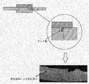
- the present inventors have confirmed that the cause of head dropout occurs during the caulking process for fixing the rivet type contact. That is, during caulking, stress is concentrated from a plurality of directions at the base of the foot. This stress concentration part is a part corresponding to the joint interface between the head part (contact material) and the foot part (base material). However, since their workability and hardness are different, as shown in FIG. A caulking wrinkle occurs near the base of the part. This caulking is a starting point of cracking in the process of use after fixing the contact. Then, as the crack grows, the head falls off (FIG. 1).
- the present inventors have (i) the base material on the side surface of the head. It was considered preferable to apply the two structures of not being exposed and (ii) not forming a bonding interface of different materials at the base of the foot. Then, the present invention has been conceived as a two-layer rivet type contact having these conditions.
- the present invention is a rivet type contact comprising a head made of a contact material and a foot that is narrower than the head and deforms when fixed, and the foot is an end on the head side.
- the heel portion is embedded in the head so that the lower end surface of the heel portion and the lower end surface of the head portion are substantially flat.
- the length (l) between the head and the foot starting point is a rivet-type contact where l ⁇ L with respect to the length (L) between the extreme end of the head and the foot starting point.
- the rivet type contact according to the present invention forms a heel portion having a diameter larger than that of the foot portion at the end portion on the head side with respect to the shape of the foot portion.
- the head and foot are joined to form a rivet-type contact.
- the rivet type contact according to the present invention has a length (l) between the extreme end of the heel and the foot starting point at the lower end surface of the head so that the extreme end of the head and the foot starting point are L ⁇ L with respect to the length (L) between.
- the base material is not exposed on the side surface of the head by making the width of the collar smaller than the width of the head and embedding the entire collar in the head. Thereby, peeling due to consumption of the contact material can be suppressed.
- the width l of the collar is too large, the possibility that the base material is exposed increases and the possibility of peeling occurs.
- the width l of the buttocks is 0.5 L ⁇ l ⁇ 0.9 L.
- the burial depth (x) of the buttocks is 1/10 to 1/3 of the height (Y) of the head. If the embedding depth is too shallow, bonding may be insufficient and the foot may drop off. Conversely, if the embedding depth is too deep, the contact material becomes thinner and the durability is insufficient. Therefore, the above range is preferable from the balance between the bonding strength and the securing of the thickness of the contact material. In addition, about the burial depth of a collar part, when the collar part upper surface as mentioned later is a curved surface, let the deepest part be a burial depth.
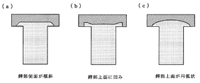
- the side may be parallel to the side of a head (Drawing 2), but may be inclined (Drawing 3 (a)).
- the upper surface of the collar portion may be flat, but may have a recess (FIG. 3B), and the upper surface of the collar portion may be arcuate (FIG. 3 ( c)).
- the contact material forming the head is preferably an Ag-based contact material. Specifically, it is pure Ag or an Ag alloy (Ag—Ni alloy, Ag—Cu alloy, etc.). As the Ag alloy, an oxide-dispersed Ag alloy (Ag—SnO 2 alloy, Ag—SnO 2 —In 2 O 3 alloy, Ag—ZnO alloy, etc.) can also be applied. Further, Cu or a Cu alloy (Cu—Ni alloy, Cu—Sn alloy, or the like) can be applied as a base material constituting the foot portion having the heel portion.
- a foot portion with a heel portion and a head portion with a recess for embedding the heel portion may be respectively produced and joined together.
- this method cannot be said to have good production efficiency, and there is a possibility that the joint strength between the foot and the head cannot be secured.
- a bonding material is manufactured by abutting and pressing a first billet made of a contact material and a second billet made of a base material, and having a concave space
- a joining die having a cylindrical space is formed to form a rivet-shaped space, and the joining material is press-fitted into the joining punch space from the lower part of the joining die, and the joining punch is inserted into the joining punch space. While the head is formed while filling one billet, a part of the second billet is embedded in the head to form a collar portion.
- a first billet made of a contact material and a second billet made of a base material are pressure-welded to form a bonding material.
- This manufacturing process of the bonding material is an essential process for manufacturing the rivet type contact according to the present invention.
- the flange portion can be formed by following the deformation of the first billet (head) at the time of the next head forming step. . Therefore, it is preferable that the load at the time of this pressure contact be 0.5 to 2.0 ton ⁇ f.
- the rivet-type contact can be made by press-fitting the manufactured bonding material into a mold formed by a combination of a bonding punch and a bonding die.
- the first billet press-fitted into the space of the joining punch is deformed by the wall surface of the joining punch to become a head shape, and the joining surface of the joining material follows this deformation and is parted together with a part of the second billet.
- the load in the press-fitting of the bonding material may be any load that can deform and process the first billet, and can be adjusted according to the type of contact material of the first billet.
- the above manufacturing of the joining material and molding by press-fitting can be performed at room temperature. And about the rivet type
- the rivet type contact according to the present invention has a two-layer structure in which the contact material and the base material are combined.
- mold contact The figure explaining the structure of the 2 layer rivet type
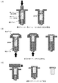
- FIG. 4 illustrates a manufacturing process of the rivet type contact according to the present embodiment.
- a cylindrical first billet (dimensions: ⁇ 1.4 mm, 0.87 mm) is cut out from a wire of an Ag alloy (Ag—SnO 2 —In 2 O 3 alloy), and a cylindrical second billet (from a Cu wire) Dimensions: ⁇ 1.4 mm, 1.10 mm) were cut out.
- the first billet and the second billet were overlapped and inserted into a joining die, and both were pressed to form a joining material.
- the joining die has a hole diameter of 1.45 mm made of cemented carbide.
- the load for this joining was 0.9 ton ⁇ f.
- the first billet and the second billet are inserted into the joining die and joined.
- the hole diameter of the die for inserting the first billet and the second billet is preferably 0.05 to 0.15 mm larger than the billet diameter.
- a joining punch was set on the joining die, and the joining material was processed into a rivet shape.
- the joining punch is made of cemented carbide and has a disk-shaped space with curved side surfaces (dimensions: upper surface ⁇ 1.68 mm, lower surface ⁇ 1.8 mm, height 0.7 mm).
- the bonding material was pressed into the space of the bonding punch from below the bonding die to deform the first billet portion into a head shape.
- the joining surface of the joining material was also deformed following the deformation of the first billet portion to form the outer shape of the collar portion.
- the joining punch was moved, and the upper surface of the head was pressed and molded.
- the dimensions of the rivet type contact manufactured as described above are as follows: the head is ⁇ 2.5 mm thick, 0.35 mm, the foot is ⁇ 1.5 mm, and the length is 0.8 mm, and the heel is ⁇ 2.0 mm at the lower end surface of the head. The height was 0.1 mm.
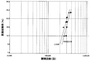
- a rivet type contact was attached as a fixed contact to a hinge-type AC general-purpose relay, and the open / close operation was repeated under the condition of energized load, and the number of endurance life switching until failure occurred was measured.
- a test was also performed on a rivet-type contact having the same shape as FIG. 7A and having the same Ag alloy as that of the present embodiment joined as a contact material to a Cu base material. Test conditions in the evaluation test are as follows.
- Test voltage AC100V Test current: 10A Load: Resistance load switching frequency: 1 second ON / 10 seconds OFF Contact force: 1.96 ⁇ 10 ⁇ 1 N (20 gf) Moving contact dimensions: ⁇ 3.0mm x t0.35mm
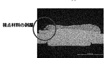
- FIG. 6 is an enlarged photograph of the head of the rivet type contact of the comparative example after the durability test. The end of the contact material is heavily consumed, and the contact material is peeled off.
- the contact material is prevented from being peeled off or dropped off during use.
- an improvement in the durability life is added to the original characteristic of the two-layer rivet type contact that reduces the amount of the contact material used and suppresses the member cost.
Landscapes
- Engineering & Computer Science (AREA)
- Manufacturing & Machinery (AREA)
- Chemical & Material Sciences (AREA)
- Composite Materials (AREA)
- Materials Engineering (AREA)
- Physics & Mathematics (AREA)
- Electromagnetism (AREA)
- Manufacture Of Switches (AREA)
- Contacts (AREA)
- Insertion Pins And Rivets (AREA)
Abstract
Description
試験電流:10A
負荷:抵抗負荷
開閉頻度:1秒ON/10秒OFF
接触力:1.96×10⁻¹N(20gf)
可動接点寸法:φ3.0mm×t0.35mm
Claims (8)
- 接点材料からなる頭部と、前記頭部より幅狭であり固定時において変形する足部よりなるリベット型接点であって、
前記足部は、前記頭部側の端部に足部より大径の鍔部を備え、
前記鍔部は、その下端面と頭部の下端面とが略フラットになるように、頭部に埋接されており、
前記鍔部の最端部と足部起点との間の長さ(l)が、前記頭部の最端部と足部起点との間の長さ(L)に対してl<Lであるリベット型接点。 - lがLに対して、0.5L≦l≦0.9Lである請求項1記載のリベット型接点。
- 鍔部の埋接深さは、頭部の高さに対して1/10~1/3である請求項1又は請求項2記載のリベット型接点。
- 接点材料は、Ag又はAg合金からなる請求項1~請求項3のいずれかに記載のリベット型接点。
- 足部は、Cu又はCu合金からなる請求項1~請求項4のいずれかに記載のリベット型接点。
- 請求項1~請求項3のいずれかに記載のリベット型接点の製造方法であって、
接点材料からなる第1ビレットとベース材料からなる第2ビレットとを突き合わせて圧接して接合材を製造し、
凹状の空間を有する接合パンチと、筒状の空間を有する接合ダイスとを組み合わせてリベット形状の空間を形成し、
前記接合材を、前記接合ダイスの下部から前記接合パンチの空間に圧入し、
前記接合パンチ内の空間に第1ビレットを充填して頭部を形成すると共に、第2ビレットの一部を頭部に埋接して鍔部を形成するリベット型接点の製造方法。 - 第1ビレットと第2ビレットとを圧接して接合材とする工程は、0.5~2ton・fの荷重による圧接である請求項6記載のリベット型接点の製造方法。
- 頭部及び鍔部を形成後、頭部をプレス加工して成型する工程を含む請求項6又は請求項7記載のリベット型接点の製造方法。
Priority Applications (5)
| Application Number | Priority Date | Filing Date | Title |
|---|---|---|---|
| JP2013556692A JP6023092B2 (ja) | 2012-12-14 | 2013-12-13 | リベット型接点及びその製造方法 |
| CN201380065246.0A CN104871273B (zh) | 2012-12-14 | 2013-12-13 | 铆钉型接点及其制造方法 |
| US14/649,263 US10490376B2 (en) | 2012-12-14 | 2013-12-13 | Rivet-type contact and method for manufacturing the same |
| DE112013005976.2T DE112013005976B4 (de) | 2012-12-14 | 2013-12-13 | Nietenkontakt und Verfahren zu dessen Herstellung |
| US16/692,227 US11145478B2 (en) | 2012-12-14 | 2019-11-22 | Rivet-type contact and method for manufacturing the same |
Applications Claiming Priority (2)
| Application Number | Priority Date | Filing Date | Title |
|---|---|---|---|
| JP2012273136 | 2012-12-14 | ||
| JP2012-273136 | 2012-12-14 |
Related Child Applications (2)
| Application Number | Title | Priority Date | Filing Date |
|---|---|---|---|
| US14/649,263 A-371-Of-International US10490376B2 (en) | 2012-12-14 | 2013-12-13 | Rivet-type contact and method for manufacturing the same |
| US16/692,227 Continuation US11145478B2 (en) | 2012-12-14 | 2019-11-22 | Rivet-type contact and method for manufacturing the same |
Publications (1)
| Publication Number | Publication Date |
|---|---|
| WO2014092173A1 true WO2014092173A1 (ja) | 2014-06-19 |
Family
ID=50934454
Family Applications (1)
| Application Number | Title | Priority Date | Filing Date |
|---|---|---|---|
| PCT/JP2013/083421 Ceased WO2014092173A1 (ja) | 2012-12-14 | 2013-12-13 | リベット型接点及びその製造方法 |
Country Status (6)
| Country | Link |
|---|---|
| US (2) | US10490376B2 (ja) |
| JP (1) | JP6023092B2 (ja) |
| CN (1) | CN104871273B (ja) |
| DE (1) | DE112013005976B4 (ja) |
| MY (1) | MY169148A (ja) |
| WO (1) | WO2014092173A1 (ja) |
Families Citing this family (6)
| Publication number | Priority date | Publication date | Assignee | Title |
|---|---|---|---|---|
| ES2759262T5 (es) | 2015-04-13 | 2022-11-30 | Hitachi Energy Switzerland Ag | Dispositivo para interrumpir solo corrientes que no son de cortocircuito, en particular seccionador o conmutador de puesta a tierra |
| US11428257B2 (en) * | 2018-09-24 | 2022-08-30 | Liquidmetal Technologies, Inc. | Amorphous metal rivet systems |
| JP6580290B1 (ja) * | 2018-11-30 | 2019-09-25 | 三菱電機株式会社 | 電気接触子およびその製造方法 |
| CN109488672A (zh) * | 2019-01-16 | 2019-03-19 | 佛山市巨隆金属制品有限公司 | 一种包不锈钢头铆钉及其制作方法 |
| DE102020209161B3 (de) | 2020-07-21 | 2021-11-18 | Vitesco Technologies Germany Gmbh | Leistungsschalter zur Anordnung in einer Schaltsicherungsbox und Schaltsicherungsbox für ein Kraftfahrzeug |
| KR20220162465A (ko) * | 2021-06-01 | 2022-12-08 | 현대자동차주식회사 | 고내구 전기 접점 구조 |
Citations (2)
| Publication number | Priority date | Publication date | Assignee | Title |
|---|---|---|---|---|
| JPS61101920A (ja) * | 1984-10-23 | 1986-05-20 | 田中貴金属工業株式会社 | チユ−ブラ接点の製造方法 |
| JPS62163213A (ja) * | 1986-09-19 | 1987-07-20 | 田中貴金属工業株式会社 | 複合電気接点 |
Family Cites Families (18)
| Publication number | Priority date | Publication date | Assignee | Title |
|---|---|---|---|---|
| US2032926A (en) | 1935-02-01 | 1936-03-03 | Gen Electric | Electrical contact |
| US2181083A (en) | 1936-01-02 | 1939-11-21 | Metals & Controls Corp | Laminated contact |
| DE850031C (de) | 1943-03-09 | 1952-09-22 | Eugen Dr-Ing Duerrwaechter | Bimetallkontakte |
| US3026603A (en) | 1958-10-13 | 1962-03-27 | Kelsey Hayes Co | Method of making electrical contacts and the like |
| US3191276A (en) * | 1959-12-01 | 1965-06-29 | Talon Inc | Method of making composite electrical contact bodies |
| US3311729A (en) * | 1965-10-04 | 1967-03-28 | Deringer Mfg Company | Electrical contact and method of forming the same |
| US3547334A (en) * | 1967-05-25 | 1970-12-15 | Contacts Inc | Apparatus for making cold bonded electrical composite contacts |
| JPS4821863B1 (ja) * | 1968-08-02 | 1973-07-02 | ||
| US3666160A (en) * | 1970-06-30 | 1972-05-30 | Contacts Inc | Method and apparatus for feeding discrete parts to a cold heading machine |
| JPS5542453B2 (ja) * | 1973-12-29 | 1980-10-30 | ||
| JPS5673826A (en) * | 1979-11-22 | 1981-06-18 | Chugai Electric Ind Co Ltd | Method of manufacturing composite electric contact by cold solderless bonding |
| JPH02227919A (ja) * | 1989-03-01 | 1990-09-11 | Tanaka Kikinzoku Kogyo Kk | リベット型接点 |
| DE3915192A1 (de) | 1989-05-10 | 1990-11-15 | Focke & Co | Verfahren und vorrichtung zum herstellen von (folien-)verpackungen sowie (folien-)verpackung |
| JPH05282957A (ja) | 1992-03-27 | 1993-10-29 | Tanaka Kikinzoku Kogyo Kk | リベット型クラッド電気接点の製造方法 |
| JP4024580B2 (ja) | 2002-04-12 | 2007-12-19 | 三桜工業株式会社 | パイプ曲げ加工装置のパイプ曲げ加工ユニット |
| JP3098834U (ja) | 2003-06-26 | 2004-03-18 | 中外電気工業株式会社 | 電気接点 |
| WO2009098836A1 (en) * | 2008-02-08 | 2009-08-13 | Fuji Electric Fa Components & Systems Co., Ltd. | Manufacturing method of electric contact and manufacturing equipment of electric contact |
| CN102842448A (zh) * | 2011-06-24 | 2012-12-26 | 三菱综合材料C.M.I.株式会社 | 复合触点的制造方法 |
-
2013
- 2013-12-13 CN CN201380065246.0A patent/CN104871273B/zh active Active
- 2013-12-13 DE DE112013005976.2T patent/DE112013005976B4/de active Active
- 2013-12-13 US US14/649,263 patent/US10490376B2/en active Active
- 2013-12-13 JP JP2013556692A patent/JP6023092B2/ja active Active
- 2013-12-13 MY MYPI2015701581A patent/MY169148A/en unknown
- 2013-12-13 WO PCT/JP2013/083421 patent/WO2014092173A1/ja not_active Ceased
-
2019
- 2019-11-22 US US16/692,227 patent/US11145478B2/en active Active
Patent Citations (2)
| Publication number | Priority date | Publication date | Assignee | Title |
|---|---|---|---|---|
| JPS61101920A (ja) * | 1984-10-23 | 1986-05-20 | 田中貴金属工業株式会社 | チユ−ブラ接点の製造方法 |
| JPS62163213A (ja) * | 1986-09-19 | 1987-07-20 | 田中貴金属工業株式会社 | 複合電気接点 |
Also Published As
| Publication number | Publication date |
|---|---|
| US20160217956A1 (en) | 2016-07-28 |
| JPWO2014092173A1 (ja) | 2017-01-12 |
| CN104871273B (zh) | 2017-12-19 |
| DE112013005976T5 (de) | 2015-11-26 |
| US20200090890A1 (en) | 2020-03-19 |
| US10490376B2 (en) | 2019-11-26 |
| CN104871273A (zh) | 2015-08-26 |
| DE112013005976B4 (de) | 2023-03-16 |
| JP6023092B2 (ja) | 2016-11-09 |
| US11145478B2 (en) | 2021-10-12 |
| MY169148A (en) | 2019-02-18 |
Similar Documents
| Publication | Publication Date | Title |
|---|---|---|
| JP6023092B2 (ja) | リベット型接点及びその製造方法 | |
| US8723320B2 (en) | Power module and manufacturing method thereof | |
| JP6051298B2 (ja) | リベット型接点及びその製造方法 | |
| JP5948385B2 (ja) | 点火プラグ用電極を製造するためのクラッド構造を有するテープ材 | |
| US20230021593A1 (en) | Terminal, terminal-equipped electric wire, connection structure, and manufacturing method of terminal-equipped electric wire | |
| JP5424811B2 (ja) | リレー用電気接点及びその製造方法 | |
| JP2013030475A (ja) | 複合接点の製造方法 | |
| CN103765708A (zh) | 火花塞用包层电极及其制造方法 | |
| JP5065993B2 (ja) | アルミ電線用圧着端子 | |
| JP2017107698A (ja) | 端子対およびコネクタ | |
| JP4074173B2 (ja) | 押釦スイッチ用部材及びその製造方法 | |
| JP2014089832A (ja) | スイッチの接点構造およびそれを用いた圧力スイッチ | |
| CN111446095A (zh) | 一种新型铆钉型三复合电触头成型方法 | |
| JPS6023448B2 (ja) | 複合接点帯材 | |
| JPH05282957A (ja) | リベット型クラッド電気接点の製造方法 | |
| CN210231055U (zh) | 一种引线框架用制备置卷装置 | |
| JP2009010070A (ja) | コンデンサ用電極箔のリード線接続装置 | |
| JP2020095861A (ja) | 接点構造、接点構造の製造方法、中間生成物及び電気機器 | |
| GB2257832A (en) | Electrical contacts. | |
| TW202414470A (zh) | 鉚釘接點及電氣接點以及電氣接點的製造方法 | |
| JP2997080B2 (ja) | 電気接点及びその製造方法 | |
| WO2017119356A1 (ja) | 複合電気接点 | |
| WO2015163439A1 (ja) | 端子接点 | |
| JP2003006587A5 (ja) | ||
| JP2001266692A (ja) | 電気接点形状とかしめ成形パンチとその製造方法 |
Legal Events
| Date | Code | Title | Description |
|---|---|---|---|
| ENP | Entry into the national phase |
Ref document number: 2013556692 Country of ref document: JP Kind code of ref document: A |
|
| 121 | Ep: the epo has been informed by wipo that ep was designated in this application |
Ref document number: 13862025 Country of ref document: EP Kind code of ref document: A1 |
|
| WWE | Wipo information: entry into national phase |
Ref document number: 14649263 Country of ref document: US |
|
| WWE | Wipo information: entry into national phase |
Ref document number: 1120130059762 Country of ref document: DE Ref document number: 112013005976 Country of ref document: DE |
|
| 122 | Ep: pct application non-entry in european phase |
Ref document number: 13862025 Country of ref document: EP Kind code of ref document: A1 |