WO2014092057A1 - 冷却装置 - Google Patents
冷却装置 Download PDFInfo
- Publication number
- WO2014092057A1 WO2014092057A1 PCT/JP2013/083004 JP2013083004W WO2014092057A1 WO 2014092057 A1 WO2014092057 A1 WO 2014092057A1 JP 2013083004 W JP2013083004 W JP 2013083004W WO 2014092057 A1 WO2014092057 A1 WO 2014092057A1
- Authority
- WO
- WIPO (PCT)
- Prior art keywords
- heat
- receiving block
- fin group
- heat pipe
- fin
- Prior art date
Links
Images


Classifications
-
- F—MECHANICAL ENGINEERING; LIGHTING; HEATING; WEAPONS; BLASTING
- F28—HEAT EXCHANGE IN GENERAL
- F28D—HEAT-EXCHANGE APPARATUS, NOT PROVIDED FOR IN ANOTHER SUBCLASS, IN WHICH THE HEAT-EXCHANGE MEDIA DO NOT COME INTO DIRECT CONTACT
- F28D15/00—Heat-exchange apparatus with the intermediate heat-transfer medium in closed tubes passing into or through the conduit walls ; Heat-exchange apparatus employing intermediate heat-transfer medium or bodies
- F28D15/02—Heat-exchange apparatus with the intermediate heat-transfer medium in closed tubes passing into or through the conduit walls ; Heat-exchange apparatus employing intermediate heat-transfer medium or bodies in which the medium condenses and evaporates, e.g. heat pipes
- F28D15/0275—Arrangements for coupling heat-pipes together or with other structures, e.g. with base blocks; Heat pipe cores
-
- F—MECHANICAL ENGINEERING; LIGHTING; HEATING; WEAPONS; BLASTING
- F28—HEAT EXCHANGE IN GENERAL
- F28F—DETAILS OF HEAT-EXCHANGE AND HEAT-TRANSFER APPARATUS, OF GENERAL APPLICATION
- F28F1/00—Tubular elements; Assemblies of tubular elements
- F28F1/10—Tubular elements and assemblies thereof with means for increasing heat-transfer area, e.g. with fins, with projections, with recesses
- F28F1/12—Tubular elements and assemblies thereof with means for increasing heat-transfer area, e.g. with fins, with projections, with recesses the means being only outside the tubular element
- F28F1/24—Tubular elements and assemblies thereof with means for increasing heat-transfer area, e.g. with fins, with projections, with recesses the means being only outside the tubular element and extending transversely
- F28F1/32—Tubular elements and assemblies thereof with means for increasing heat-transfer area, e.g. with fins, with projections, with recesses the means being only outside the tubular element and extending transversely the means having portions engaging further tubular elements
-
- F—MECHANICAL ENGINEERING; LIGHTING; HEATING; WEAPONS; BLASTING
- F28—HEAT EXCHANGE IN GENERAL
- F28F—DETAILS OF HEAT-EXCHANGE AND HEAT-TRANSFER APPARATUS, OF GENERAL APPLICATION
- F28F13/00—Arrangements for modifying heat-transfer, e.g. increasing, decreasing
-
- F—MECHANICAL ENGINEERING; LIGHTING; HEATING; WEAPONS; BLASTING
- F28—HEAT EXCHANGE IN GENERAL
- F28F—DETAILS OF HEAT-EXCHANGE AND HEAT-TRANSFER APPARATUS, OF GENERAL APPLICATION
- F28F3/00—Plate-like or laminated elements; Assemblies of plate-like or laminated elements
- F28F3/02—Elements or assemblies thereof with means for increasing heat-transfer area, e.g. with fins, with recesses, with corrugations
- F28F3/022—Elements or assemblies thereof with means for increasing heat-transfer area, e.g. with fins, with recesses, with corrugations the means being wires or pins
-
- H—ELECTRICITY
- H05—ELECTRIC TECHNIQUES NOT OTHERWISE PROVIDED FOR
- H05K—PRINTED CIRCUITS; CASINGS OR CONSTRUCTIONAL DETAILS OF ELECTRIC APPARATUS; MANUFACTURE OF ASSEMBLAGES OF ELECTRICAL COMPONENTS
- H05K7/00—Constructional details common to different types of electric apparatus
- H05K7/20—Modifications to facilitate cooling, ventilating, or heating
- H05K7/20009—Modifications to facilitate cooling, ventilating, or heating using a gaseous coolant in electronic enclosures
- H05K7/20136—Forced ventilation, e.g. by fans
- H05K7/20154—Heat dissipaters coupled to components
-
- H—ELECTRICITY
- H05—ELECTRIC TECHNIQUES NOT OTHERWISE PROVIDED FOR
- H05K—PRINTED CIRCUITS; CASINGS OR CONSTRUCTIONAL DETAILS OF ELECTRIC APPARATUS; MANUFACTURE OF ASSEMBLAGES OF ELECTRICAL COMPONENTS
- H05K7/00—Constructional details common to different types of electric apparatus
- H05K7/20—Modifications to facilitate cooling, ventilating, or heating
- H05K7/2089—Modifications to facilitate cooling, ventilating, or heating for power electronics, e.g. for inverters for controlling motor
- H05K7/20936—Liquid coolant with phase change
-
- F—MECHANICAL ENGINEERING; LIGHTING; HEATING; WEAPONS; BLASTING
- F28—HEAT EXCHANGE IN GENERAL
- F28F—DETAILS OF HEAT-EXCHANGE AND HEAT-TRANSFER APPARATUS, OF GENERAL APPLICATION
- F28F13/00—Arrangements for modifying heat-transfer, e.g. increasing, decreasing
- F28F2013/005—Thermal joints
- F28F2013/006—Heat conductive materials
-
- F—MECHANICAL ENGINEERING; LIGHTING; HEATING; WEAPONS; BLASTING
- F28—HEAT EXCHANGE IN GENERAL
- F28F—DETAILS OF HEAT-EXCHANGE AND HEAT-TRANSFER APPARATUS, OF GENERAL APPLICATION
- F28F2215/00—Fins
- F28F2215/04—Assemblies of fins having different features, e.g. with different fin densities
-
- F—MECHANICAL ENGINEERING; LIGHTING; HEATING; WEAPONS; BLASTING
- F28—HEAT EXCHANGE IN GENERAL
- F28F—DETAILS OF HEAT-EXCHANGE AND HEAT-TRANSFER APPARATUS, OF GENERAL APPLICATION
- F28F2275/00—Fastening; Joining
- F28F2275/04—Fastening; Joining by brazing
-
- F—MECHANICAL ENGINEERING; LIGHTING; HEATING; WEAPONS; BLASTING
- F28—HEAT EXCHANGE IN GENERAL
- F28F—DETAILS OF HEAT-EXCHANGE AND HEAT-TRANSFER APPARATUS, OF GENERAL APPLICATION
- F28F2275/00—Fastening; Joining
- F28F2275/12—Fastening; Joining by methods involving deformation of the elements
- F28F2275/122—Fastening; Joining by methods involving deformation of the elements by crimping, caulking or clinching
Definitions
- the present invention relates to a cooling device that cools a heat generating element, and more particularly, to a cooling device that cools an electrical component such as a power conversion device mounted on a moving body such as a railway vehicle, an aircraft, or a ship by air cooling.
- a moving body such as a railway vehicle includes a power control device including a power device such as an IGBT and other electronic components in a power control housing in order to control a drive motor and the like. Since these electronic components generate heat due to heat loss, a cooling device is provided on the heating element so as to efficiently cool the attached electrical components using forced air cooling or wind generated by vehicle movement.
- a power control device including a power device such as an IGBT and other electronic components in a power control housing in order to control a drive motor and the like. Since these electronic components generate heat due to heat loss, a cooling device is provided on the heating element so as to efficiently cool the attached electrical components using forced air cooling or wind generated by vehicle movement.
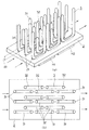
- the cooling device 1 includes a heat receiving block 2 to which electronic parts H ⁇ b> 1 and H ⁇ b> 2 that are heating elements are attached, a heat pipe 3 to be soldered to the heat receiving block 2, and a group of radiating fins attached to the heat pipe 3. 4 is formed. More specifically, as shown in FIG. 12, for example, the bottom of the heat pipe 3 is soldered to the heat receiving block 2 for attaching the heat generating element having a long hole groove 21 for fixing the heat pipe 3 on one side as the heat receiving portion.
- the heat-dissipating fin 4 having a circular burring is press-fitted into the soldered heat pipe 3 and is generally configured.
- the fin pitch is changed between the windward side and the leeward side in order to improve the cooling efficiency of the entire cooling device without increasing the number of radiating fins and the amount of cooling air.
- Patent Document 1 Various ideas have been made (see Patent Document 1).
- a heat pipe 3 having a U-shape (or L-shape) in side view may be used for the purpose of improving the cooling effect.
- the heat receiving block may be required to be thin for the purpose of reducing the weight of the cooling device. Then, as shown in FIG. 12, an R shape of a bent portion of the U-shaped or L-shaped heat pipe appears on the heat receiving block in the vicinity of the joining portion of the heat receiving block and the heat pipe.
- radiating fins are provided with burring holes according to the positions where the heat pipes are provided, and the heat radiating fins and the heat pipes are pressure-bonded by press-fitting the heat pipes into the holes.
- the bent portion of the U-shaped or L-shaped heat pipe appears on the heat receiving block, it is difficult to bring the bent portion of the heat pipe into close contact with the hole of the radiating fin.
- region becomes the dead space D. This dead space D cannot be expected to contribute to heat dissipation because fins are not arranged. Further, since the wind blows out to the dead space D, the entire fin cannot receive the wind evenly, and there is a concern that the cooling capacity is lowered.
- the present invention has been proposed in order to solve the above-described problems of the prior art.
- the purpose of the present invention is to dispose heat radiation fins in the bent portion of the heat pipe in the vicinity of the heat receiving block, and the entire heat radiation fin. It is in providing the cooling device which improved the cooling capacity by receiving a wind equally.
- a first invention includes a heat receiving block that is thermally connected to a heating element, and a heat pipe that is erected on the surface of the heat receiving block and receives heat from the heat receiving block and transports heat. And a plurality of fins provided on the heat pipe, and the heat pipe is formed in a straight line in a direction away from the bent heat-receiving block and the heat-receiving block from the bent portion.
- the fin includes a first fin group installed on the linear part, and a second fin group installed on the bent part, and the second fin group includes:
- Each fin has a hole having an area equal to or larger than the cross section of the bent portion, and is thermally connected to the heat receiving block by a connection member that fixes the second fin group to the heat receiving block.
- the second fin installed in the bent portion of the U-shaped or L-shaped heat pipe has a hole having an area equal to or larger than the cross section of the bent portion, so that the heat dissipating fin is provided in the conventional structure.
- a heat radiating fin can also be provided at the bent portion of the heat pipe where it is difficult to arrange the heat sink.
- a heat conductive connecting member such as an aluminum pin or a copper pin
- the fins can be arranged in the conventional dead space to improve the cooling capacity, and the air can be evenly received throughout the fin without being blown out at the bent portion. . Furthermore, since it is possible to dispose heat radiating fins in the former dead space, the number of heat radiating fins arranged opposite to the space of the cooling device is reduced. It is also possible to make it easier.
- the second invention is characterized in that, in the first invention, some of the fins of the first fin group are thermally connected to the heat receiving block by the connecting member.
- a part of the first fin group provided in the straight portion that forms the straight portion of the heat pipe is also thermally connected to the heat receiving block by the connecting member separately from the thermal connection to the heat pipe. Is done.
- the heat of the heat receiving block is absorbed through the connection member separately from the heat pipe and is transported to the fins, thereby improving the heat dissipation.
- the 1st fin group is thermally connected also with the heat pipe, it does not stop at the above-mentioned effect. That is, when the cooling device is used in a low temperature environment, the working fluid in the heat pipe may freeze.
- connection member thermally connects the heat pipe and the second fin group between the outer periphery of the bent portion and the inner periphery of the hole. It is characterized by being inserted as follows.
- These can be thermally connected by inserting a connecting member between the outer periphery of the two.
- the fins can be arranged in the conventional dead space to improve the cooling capacity, and the air can be evenly received throughout the fin without being blown out at the bent portion. .
- the cooling device is used in a low temperature environment, the heat from the connecting member is transferred to the heat pipe, so that the melting of the working fluid is promoted, and the heat dissipation efficiency is quickly increased when the cooling device is started in the low temperature environment. It becomes possible to raise.
- the hole of the second fin group has an elliptical shape
- the connection member has an outer periphery that is substantially the same size as the elliptical shape of the hole. It is an elliptical cylindrical body provided with an inner circumference that is substantially the same size as the outer circumference.
- the second fin group is press-fitted into the elliptic cylindrical body, the second fin group is fixed on the outer peripheral surface of the elliptic cylindrical body, and the heat pipe is in close contact with the inner peripheral surface.
- the second fin group and the heat pipe can be thermally connected.
- the hole of the second fin group is subjected to burring, and the connection member, the heat pipe, and the second fin group are The thermal connection is wider than the thickness of the fin.
- the heat pipe and the fin can be brought into contact with each other in a wide area even in the bent portion of the heat pipe, and the cooling capacity Can be improved.
- a cooling device in which the heat radiation fins are arranged also in the bent portion of the heat pipe in the vicinity of the heat receiving block, and the entire heat radiation fin receives wind evenly, thereby improving the cooling capacity. Can be provided.
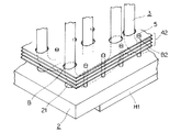
- the cooling device 10 As shown in FIG. 1, the cooling device 10 according to the first embodiment of the present invention includes a heat receiving block 2 that is thermally connected to the electronic components H ⁇ b> 1 and H ⁇ b> 2 that constitute the heating element, and a surface of the heat receiving block 2.
- a heat pipe 3 that is erected and receives heat from the heat receiving block 2 and transports heat, and a plurality of fins 4 provided on the heat pipe 3 are provided.
- the heat receiving block 2 is connected to the electronic components H ⁇ b> 1 and H ⁇ b> 2 on one side of the rectangular shape (the bottom side in the figure), and a plurality of heat pipes 3 stand on the other side (the plane side in the figure). It is installed. More specifically, a plurality of long hole grooves 21 for fixing a plurality of heat pipes 3 are provided on the other surface side of the heat receiving block 2 so that the major axis direction is aligned with the wind direction indicated by an arrow in the figure. Yes.
- the U-shaped bottom end side of the heat pipe 3 is buried in the long hole groove 21 and fixed by a method such as soldering or caulking.
- the heat pipe 3 uses a U-shape.
- two types of a long HP 31 and a short HP 32 are provided on the heat receiving block 2.
- the heat pipe 3 is U-shaped, and is formed of a bent portion 33 provided in the vicinity of the heat receiving block 2 and a straight portion 34 formed linearly in a direction away from the heat receiving block from the bent portion 33.
- the bending part 33 does not say the whole part which makes the U-shaped bending of the heat pipe 3, but as shown to Fig.2 (a), the heat pipe 3 attached to the heat receiving block 2 is shown. The part from the part which appears on the plane of the heat receiving block 2 to the straight part is indicated. Further, in this embodiment, only an example using a U-shaped heat pipe is shown, but in the present invention, any heat pipe having a straight portion and a bent portion such as an L-shaped heat pipe can be applied. It is.
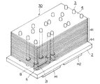
- the fin 4 is comprised from the 1st fin group 41 installed in the linear part 34 of the heat pipe 3, and the 2nd fin group 42 installed in the bending part 33, as shown in FIG.
- the four fins on the heat receiving block 2 side are configured as the second fin group 42.
- the second fin group 42 is not limited to four.
- the first fin group 41 has the same configuration as that shown in FIG. 12 as the prior art, and a plurality of circular burrings B1 are provided on the surface of each fin, and the circular burring B1 to the heat pipe 3 are provided.
- the straight portion 34 is press-fitted and fixed at a predetermined position.
- the second fin group 42 is an elliptical escape hole having an area equivalent to the maximum area of the cross section of the bent portion 33 of the heat pipe 3 at a position corresponding to the heat pipe 3.
- a plurality of B are provided on the surface.
- the escape hole B only needs to be arranged so that the fins that pass through the bent portion 33 and form the second fin group 42 can be stacked, and in this case, the contact with the heat pipe 3 is not hindered, You may be in the state which is not contacting. That is, it does not matter whether there is thermal exchange by contact.
- the first fin group 41 is omitted for convenience of explanation.
- the second fin group 42 is provided with a burring B2 at a position corresponding to the pin 5 on the heat receiving block 2 of each fin in addition to the escape hole B described above.
- the second fin group 42 is fixed to the heat receiving block 2 by press-fitting the pin 5 from the burring B2, and is thereby thermally connected to the heat receiving block 2 and the pin 5.
- the pins 5 are arranged in accordance with the arrangement of the heat pipes 3. For example, in this embodiment, ten pins are arranged in a row in the wind direction direction, and seven rows are provided (see FIGS. 3 and 4). Moreover, it is preferable that the pin 5 is comprised with aluminum and copper with high heat conductivity.
- the heat transport path of the cooling device 10 is transferred from the electronic components H1 and H2 serving as heat sources via the heat receiving block 2 to the first fin group 41 through heat transport from the heat receiving side of the heat pipe 3 to the heat radiating side.
- Two routes are formed: a route to be heated, and a route to transfer heat from the electronic components H1 and H2 to the pin 5 through the heat receiving block 2 and transfer heat from the pin 5 to the second fin group 42.
- the second fin group 42 for the bent portion 33, which is difficult to fix the heat dissipating fins due to the conventional structure and difficult to adhere to even if fixed.
- the second fin group 42 is provided with a plurality of relief holes B on the surface having the same area as the maximum area of the cross section of the bent portion 33, and the heat radiation fin 4 is fixed and the heat receiving block 2 is thermally connected.
- a simple connection is made by the pin 5 made of a thermally conductive connecting member such as aluminum or copper.
- the heat of the heat receiving block 2 can be transmitted to the heat radiating fins 4 without using the heat pipes 3 by the pins 5.
- the radiation fin 4 can be arrange
- the entire fin 4 including the first fin group 41 can receive the wind evenly without blowing through this portion. become.
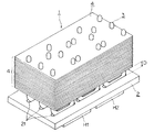
- the cooling device 20 according to the second embodiment of the present invention is based on the configuration of the first embodiment, and the third fin formed in the straight portion of the heat pipe 3 as a part of the first fin group 41.
- the point which provided the group 43 has the characteristic on a structure. Therefore, in the following, the configuration of the third fin group 43 and the configuration different from the first embodiment in relation to this configuration will be described, and description of the same configuration as the first embodiment will be omitted.
- the fin 4 is configured by three fin groups, a first fin group 41, a second fin group 42, and a third fin group 43.
- the third fin group 43 is located on the upper side of the second fin group 42 in the drawing, away from the heat receiving block 2, and between the first fin group 41.
- the first fin group 41 and the second fin group 42 are the same as those in the first embodiment except that the number of the first fin groups 41 is different.
- the third fin group 43 is formed of four fins as in the second fin group 42. Unlike the second fin group 42, the third fin group 43 is formed on the straight portion 34 (see FIG. 2A) of the heat pipe 3. Therefore, the third fin group 43 has a plurality of circular burrings B3 on the surface of each fin. Moreover, since the 3rd fin group 43 is press-fit in the pin 50 extended
- the third fin group 43 is fixed in close contact with a predetermined position of the heat pipe 3 by press-fitting the straight portion 34 of the heat pipe 3 from the circular burring B3.
- the third fin group 43 is positioned and fixed by press-fitting the pin 50 from the burring B4.
- the third fin group 43 is thermally connected to both the heat receiving block 2 and the pin 50.
- the pin 50 is configured to be extended by four fins 4 longer than the pin 5 in the first embodiment.
- the heat transport path in the cooling device 20 of the present embodiment configured as described above is as follows.
- the heat transport path of the cooling device 20 passes through the heat transport from the heat receiving side 2 of the heat pipe 3 to the heat radiating side through the heat receiving block 2 from the electronic components H1 and H2 serving as heat sources, and the first fin group 41 and the first fin
- the heat is transferred from the electronic parts H1 and H2 to the pin 50 via the heat receiving block 2 and transferred from the pin 50 to the second fin group 42 and the third fin group 43. Two routes are formed.
- the cooling device 20 having such a configuration has the following effects in addition to the effects of the cooling device 10 in the first embodiment. That is, the third fin group 43 provided in the straight portion 34 of the heat pipe 3 is also thermally connected to the heat receiving block 2 by the pin 50 of the connecting member, separately from the thermal connection to the heat pipe 3.
- the heat of the heat receiving block 2 is absorbed through the pin 50 separately from the heat pipe 3 and transferred to the third fin group 43. Thereby, the heat dissipation can be improved.
- the third fin group 43 is thermally connected to the heat pipe 3, the following significant effects can be obtained as well. That is, when the cooling device 20 is used in a low temperature environment (for example, a state of ⁇ 20 ° C., the same applies hereinafter), the working fluid in the heat pipe is frozen. In this case, generally, until the working fluid melts, the heat pipe functions only as a copper tube, and the heat dissipation efficiency is lower than the original function. In this regard, in the present embodiment, the heat from the above-described pin 50 is transmitted to the heat pipe 3, so that the melting of the frozen working fluid is promoted. As described above, according to the cooling device 20, it is possible to increase the heat dissipation efficiency at an early stage particularly when the cooling device is started in a low temperature environment.
- the cooling device 30 uses the pins 5 to thermally connect and position the second fin group 42 and the heat receiving block 2 in the configuration of the first embodiment. This is performed by the elliptic cylinder member 6. As shown in FIG. 7, a fourth fin group 44 is used in place of the second fin group 42 in the first embodiment. Other configurations are the same as those in the first embodiment.
- the fourth fin group 44 has a clearance hole B having an area equivalent to the maximum area of the cross section of the bent portion 33 of the heat pipe 3 at a position corresponding to the heat pipe 3. Multiple above.
- the escape hole B is provided on the surface of each fin of the fourth fin group 44 by burring. As in the case of the first embodiment, the escape hole B only needs to be arranged by laminating the fins that pass through the bent portion 33 and form the second fin group 42.
- the fourth fin group 44 is not provided with the burring B2 that is press-fitted into the pin 5 provided in the second fin group 42.
- the elliptic cylindrical member 6 is a cylindrical body having an elliptical cross-sectional shape, and has an outer periphery slightly larger than the inner periphery of the escape hole B, and the inner periphery is formed to be equal to the outer periphery of the heat pipe 3.
- the height of the elliptic cylinder member 6 is formed slightly higher than the height at which the fourth fin group 44 is laminated, and is formed to be equivalent to the height range of the bent portion 33 of the heat pipe 3.
- the elliptic cylinder member 6 is preferably formed of a material having high thermal conductivity such as aluminum or copper, like the pin 5.
- the cooling device 30 having such a configuration, first, in a state where the heat pipe 3 is positioned in the slot 21, the heat pipe 3 is passed through the hollow portion of the oval cylindrical member 6, as shown in the cross-sectional view of FIG. 9. Next, the heat pipe 3 is positioned so that the inner peripheral surface of the elliptic cylinder member 6 is in close contact with the outer periphery of the heat pipe 3. Next, the heat pipe 3 is fixed to the heat receiving block 2 by soldering or caulking, and the elliptic cylindrical member 6 is soldered to the heat receiving block 2. At this time, the hollow portion of the oval cylindrical member 6 may be left as it is, the upper surface and the lower surface may be sealed, and the hollow portion may be evacuated, or may be filled with solder or the like.
- the elliptical cylindrical member 6 is a cylindrical body.
- the bending in the heat pipe 3 is performed.
- the shape is not limited as long as the member is inserted between the outer periphery of the portion 33 and the inner periphery of the escape hole B provided in the fourth fin group.
- a relief hole provided in the fourth fin 44 is difficult even if it is a bent portion that is difficult to fix the heat radiation fin and is difficult to adhere even if fixed.
- the fourth fin 44 can be arranged in a portion that has conventionally been a dead space to improve the cooling capacity, and the wind is not blown through the bent portion 33, and the entire fin receives wind evenly. Will be able to.
- the heat of the heat receiving block 2 can also be transmitted to the heat pipe 3 through the elliptic cylinder member 6, the working fluid in the heat pipe 3 is frozen by using the cooling device 30 in a low temperature environment. Even so, the heat transfer from the heat receiving block 2 to the heat pipe 3 through the elliptic cylinder member 6 promotes the melting of the working fluid, and it is possible to increase the heat dissipation efficiency early when the cooling device is started in a low temperature environment. It becomes.
- the cooling device 1 shown in FIG. 12 was used as a conventional example.
- the cooling device 20 in the embodiment was compared with the cooling device 30 in the third embodiment shown in FIG.
- the cooling device used for the analysis has a common configuration in which an aluminum block is used for the heat receiving block 2, the width in the wind direction is 430 mm, the width in the vertical direction perpendicular to the wind direction is 230 mm, and the thickness 22. It was 5 mm.
- the heat pipes 3 as shown in FIGS. 2A and 2B, a total of 15 pipes having a diameter of 15.88 mm were used.
- the heat pipes 3 are arranged in six rows in the wind direction indicated by an arrow in FIG. 2B, and the long HP 31 and the short HP 32 are appropriately combined.
- the maximum height from the surface of the heat receiving block 2 in a side view as shown in FIG. 4 to the end of the long HP 31 of the heat pipe 3 was set to 205 mm.
- the reason why the short HP 32 is provided is to cause the working fluid of the heat pipe 3 to melt at an early stage when starting at a low temperature in the cooling devices 20 and 30 of the second and third embodiments so as to function as a heat pipe. That is, the short HP32 has a smaller capacity than the long HP31, so that the working fluid dissolves faster.
- the width in the wind direction is 400 mm, and the vertical direction is perpendicular to the wind direction.
- the width was 200 mm, the thickness was 9.5 mm, and the fin arrangement interval was 6 mm.
- the normal temperature environment here means a state of 20 ° C.
- the rising temperature in H1 and H2 says the temperature after becoming a steady state from starting of a cooling device. For example, in this embodiment, after about 20 to 40 minutes have passed.
- the rising temperature of H1 on the upstream side was 23.9 ° C.
- the rising temperature of H2 on the downstream side was 23.2 ° C.
- the rising temperature of H1 on the upstream side was 20.9 ° C.
- the rising temperature of H2 on the downstream side was 21.7 ° C.
- the rising temperature of H1 on the upstream side was 21.5 ° C.
- the rising temperature of H2 on the downstream side was 22.5 ° C.
- the rising temperature of H1 on the upstream side was 21.5 ° C.
- the rising temperature of H2 on the downstream side was 22.5 ° C.
- the cooling capacity is improved by 13% to 6% in the first embodiment and 10% to 3% in the second and third embodiments. I understand.
- Cooling device Heat receiving block 21 Slotted hole 3 Heat pipe 31 Long length HP 32 Short HP 33 Bending portion 34 Linear portion 4 Fin 41 First fin group 42 Second fin group 43 Third fin group 44 Fourth fin group 5, 50 Pin 6 Elliptical cylindrical member B Hole B1, B2, B3, B4 Burling H1, H2 electronic components
Landscapes
- Engineering & Computer Science (AREA)
- Physics & Mathematics (AREA)
- Thermal Sciences (AREA)
- Mechanical Engineering (AREA)
- General Engineering & Computer Science (AREA)
- Microelectronics & Electronic Packaging (AREA)
- Geometry (AREA)
- Life Sciences & Earth Sciences (AREA)
- Sustainable Development (AREA)
- Cooling Or The Like Of Semiconductors Or Solid State Devices (AREA)
- Cooling Or The Like Of Electrical Apparatus (AREA)
Abstract
Description
[1.第1の実施形態]
本発明の第1の実施形態に係る冷却装置10は、図1に示すように、発熱体を構成する電子部品H1,H2に熱的に接続される受熱ブロック2と、受熱ブロック2の表面に立設され、受熱ブロック2から受熱して熱輸送を行うヒートパイプ3と、ヒートパイプ3に設けられた複数のフィン4とを備える。
本発明の第2の実施形態に係る冷却装置20は、第1の実施形態の構成を基本にしつつ、第1のフィン群41の一部分としてヒートパイプ3の直線部に形成される第3のフィン群43を設けた点に構成上の特徴を有する。そこで、以下では、第3のフィン群43の構成と、この構成に関連して第1の実施形態と異なる構成について説明し、第1の実施形態と同様の構成についての説明は省略する。
本発明の第3の実施形態に係る冷却装置30は、第1の実施形態の構成において、第2のフィン群42と受熱ブロック2との熱的な接続及び位置決め固定をピン5によって行っていたものを、楕円筒部材6により行うようにしたものである。図7に示すように、第1の実施形態における第2のフィン群42の代わりに、第4のフィン群44を用いている。なお、その他の構成は、第1の実施形態と同様である。
従来の冷却装置1においては、上流側のH1の上昇温度は23.9℃で、下流側のH2の上昇温度は23.2℃であった。
第1の実施形態における冷却装置10では、上流側のH1の上昇温度は20.9℃で、下流側のH2の上昇温度は21.7℃であった。
第2の実施形態における冷却装置20では、上流側のH1の上昇温度は21.5℃で、下流側のH2の上昇温度は22.5℃であった。
第3の実施形態における冷却装置30では、上流側のH1の上昇温度は21.5℃で、下流側のH2の上昇温度は22.5℃であった。
2 受熱ブロック
21 長穴溝
3 ヒートパイプ
31 長尺HP
32 短尺HP
33 曲げ部
34 直線部
4 フィン
41 第1のフィン群
42 第2のフィン群
43 第3のフィン群
44 第4のフィン群
5,50 ピン
6 楕円筒部材
B 穴
B1,B2,B3,B4 バーリング
H1,H2 電子部品
Claims (5)
- 発熱体に熱的に接続される受熱ブロックと、
前記受熱ブロックの表面に立設され、前記受熱ブロックから受熱して熱輸送を行うヒートパイプと、
前記ヒートパイプに設けられた複数のフィンと、を備え、
前記ヒートパイプは、受熱ブロックの近傍に設けられた曲げ部と、前記曲げ部から前記受熱ブロックと離れる方向に直線状に形成される直線部と、を備え、
前記フィンは、前記直線部に設置される第1のフィン群と、前記曲げ部に設置される第2のフィン群と、を備え、
前記第2のフィン群の各フィンは、前記曲げ部の断面と同等又はそれ以上の面積の穴を備え、前記第2のフィン群を前記受熱ブロックに固定する接続部材により前記受熱ブロックと熱的に接続したことを特徴とする冷却装置。 - 前記第1のフィン群の一部のフィンは、前記接続部材により前記受熱ブロックと熱的に接続したことを特徴とする請求項1記載の冷却装置。
- 前記接続部材は、前記曲げ部の外周と、前記穴の内周の間に、前記ヒートパイプと前記第2のフィン群とを熱的に接続するように間挿されたことを特徴とする請求項1記載の冷却装置。
- 前記第2のフィン群の前記穴は、楕円形状であり、
前記接続部材は、前記穴の楕円形状と略同大の外周を備え、前記ヒートパイプの外周と略同大の内周を備えた楕円筒状体であることを特徴とする請求項3記載の冷却装置。 - 前記第2のフィン群の前記穴は、バーリング加工が施されており、
前記第2のフィン群は、前記接続部材及び前記ヒートパイプと、前記フィンの厚みより広く熱的に接続されたことを特徴とする請求項3又は4記載の冷却装置。
Priority Applications (4)
| Application Number | Priority Date | Filing Date | Title |
|---|---|---|---|
| CN201390000854.9U CN204963630U (zh) | 2012-12-11 | 2013-12-09 | 冷却装置 |
| EP13863431.6A EP2933593A4 (en) | 2012-12-11 | 2013-12-09 | COOLING DEVICE |
| BR112015012939A BR112015012939A2 (pt) | 2012-12-11 | 2013-12-09 | aparelho de refrigeração |
| JP2014514255A JP5620032B1 (ja) | 2012-12-11 | 2013-12-09 | 冷却装置 |
Applications Claiming Priority (2)
| Application Number | Priority Date | Filing Date | Title |
|---|---|---|---|
| JP2012270853 | 2012-12-11 | ||
| JP2012-270853 | 2012-12-11 |
Publications (1)
| Publication Number | Publication Date |
|---|---|
| WO2014092057A1 true WO2014092057A1 (ja) | 2014-06-19 |
Family
ID=50934345
Family Applications (1)
| Application Number | Title | Priority Date | Filing Date |
|---|---|---|---|
| PCT/JP2013/083004 WO2014092057A1 (ja) | 2012-12-11 | 2013-12-09 | 冷却装置 |
Country Status (5)
| Country | Link |
|---|---|
| EP (1) | EP2933593A4 (ja) |
| JP (1) | JP5620032B1 (ja) |
| CN (1) | CN204963630U (ja) |
| BR (1) | BR112015012939A2 (ja) |
| WO (1) | WO2014092057A1 (ja) |
Cited By (4)
| Publication number | Priority date | Publication date | Assignee | Title |
|---|---|---|---|---|
| DE102016001966A1 (de) | 2015-02-26 | 2016-09-01 | Fanuc Corporation | Luftgekühlte Laservorrichtung mit Kühlrippen aufweisendem Wärmeübertragungsbauteil |
| WO2016146490A1 (de) * | 2015-03-18 | 2016-09-22 | R. Stahl Schaltgeräte GmbH | Kühlvorrichtung mit einer heatpipe und verfahren zur herstellung der kühlvorrichtung |
| CN106912180A (zh) * | 2015-12-23 | 2017-06-30 | 建准电机工业股份有限公司 | 散热模组 |
| WO2019229876A1 (ja) * | 2018-05-30 | 2019-12-05 | 三菱電機株式会社 | 冷却装置 |
Families Citing this family (1)
| Publication number | Priority date | Publication date | Assignee | Title |
|---|---|---|---|---|
| CN107504846A (zh) * | 2016-11-28 | 2017-12-22 | 华北理工大学 | 工程车辆用翼型热管式散热器结构 |
Citations (6)
| Publication number | Priority date | Publication date | Assignee | Title |
|---|---|---|---|---|
| JP2004071635A (ja) * | 2002-08-01 | 2004-03-04 | Fujikura Ltd | タワー型ヒートシンク |
| JP2006196786A (ja) * | 2005-01-14 | 2006-07-27 | Furukawa Electric Co Ltd:The | ヒートパイプ付ヒートシンク |
| JP3146512U (ja) * | 2008-09-08 | 2008-11-20 | 奇▲こう▼科技股▲ふん▼有限公司 | 構造を強化した放熱モジュールユニット |
| US20100270007A1 (en) * | 2009-04-23 | 2010-10-28 | Wen-Te Lin | Heat sink |
| JP2011181882A (ja) | 2010-02-08 | 2011-09-15 | Furukawa Electric Co Ltd:The | 複数のフィンピッチを有する冷却装置 |
| JP2012138439A (ja) * | 2010-12-27 | 2012-07-19 | Hitachi Ltd | 冷却装置およびそれを備えた電力変換装置 |
Family Cites Families (8)
| Publication number | Priority date | Publication date | Assignee | Title |
|---|---|---|---|---|
| JP3734895B2 (ja) * | 1996-10-02 | 2006-01-11 | 古河電気工業株式会社 | ヒートシンク |
| JPH11351769A (ja) * | 1998-06-12 | 1999-12-24 | Furukawa Electric Co Ltd:The | ヒートシンク |
| US20060175045A1 (en) * | 2004-03-19 | 2006-08-10 | Yin-Hung Chen | Heat dissipation device |
| DE102004042154B4 (de) * | 2004-08-31 | 2011-01-05 | Asia Vital Components Co., Ltd. | Kühler |
| CN2763973Y (zh) * | 2004-12-10 | 2006-03-08 | 鸿富锦精密工业(深圳)有限公司 | 散热器 |
| US7509996B2 (en) * | 2005-12-27 | 2009-03-31 | Fu Zhun Precision Industry (Shen Zhen) Co., Ltd. | Heat dissipation device |
| CN201518567U (zh) * | 2009-08-26 | 2010-06-30 | 富准精密工业(深圳)有限公司 | 散热模组 |
| CN102238847A (zh) * | 2010-04-28 | 2011-11-09 | 富准精密工业(深圳)有限公司 | 散热装置 |
-
2013
- 2013-12-09 WO PCT/JP2013/083004 patent/WO2014092057A1/ja active Application Filing
- 2013-12-09 BR BR112015012939A patent/BR112015012939A2/pt not_active IP Right Cessation
- 2013-12-09 CN CN201390000854.9U patent/CN204963630U/zh not_active Expired - Lifetime
- 2013-12-09 JP JP2014514255A patent/JP5620032B1/ja active Active
- 2013-12-09 EP EP13863431.6A patent/EP2933593A4/en not_active Withdrawn
Patent Citations (6)
| Publication number | Priority date | Publication date | Assignee | Title |
|---|---|---|---|---|
| JP2004071635A (ja) * | 2002-08-01 | 2004-03-04 | Fujikura Ltd | タワー型ヒートシンク |
| JP2006196786A (ja) * | 2005-01-14 | 2006-07-27 | Furukawa Electric Co Ltd:The | ヒートパイプ付ヒートシンク |
| JP3146512U (ja) * | 2008-09-08 | 2008-11-20 | 奇▲こう▼科技股▲ふん▼有限公司 | 構造を強化した放熱モジュールユニット |
| US20100270007A1 (en) * | 2009-04-23 | 2010-10-28 | Wen-Te Lin | Heat sink |
| JP2011181882A (ja) | 2010-02-08 | 2011-09-15 | Furukawa Electric Co Ltd:The | 複数のフィンピッチを有する冷却装置 |
| JP2012138439A (ja) * | 2010-12-27 | 2012-07-19 | Hitachi Ltd | 冷却装置およびそれを備えた電力変換装置 |
Non-Patent Citations (1)
| Title |
|---|
| See also references of EP2933593A4 * |
Cited By (8)
| Publication number | Priority date | Publication date | Assignee | Title |
|---|---|---|---|---|
| DE102016001966A1 (de) | 2015-02-26 | 2016-09-01 | Fanuc Corporation | Luftgekühlte Laservorrichtung mit Kühlrippen aufweisendem Wärmeübertragungsbauteil |
| US9871342B2 (en) | 2015-02-26 | 2018-01-16 | Fanuc Corporation | Air-cooled laser device having heat-transfer member with heat radiating fins |
| DE102016001966B4 (de) | 2015-02-26 | 2020-06-18 | Fanuc Corporation | Luftgekühlte Laservorrichtung mit Kühlrippen aufweisendem Wärmeübertragungsbauteil |
| WO2016146490A1 (de) * | 2015-03-18 | 2016-09-22 | R. Stahl Schaltgeräte GmbH | Kühlvorrichtung mit einer heatpipe und verfahren zur herstellung der kühlvorrichtung |
| CN106912180A (zh) * | 2015-12-23 | 2017-06-30 | 建准电机工业股份有限公司 | 散热模组 |
| TWI626418B (zh) * | 2015-12-23 | 2018-06-11 | 建準電機工業股份有限公司 | 散熱模組 |
| WO2019229876A1 (ja) * | 2018-05-30 | 2019-12-05 | 三菱電機株式会社 | 冷却装置 |
| US20210215433A1 (en) * | 2018-05-30 | 2021-07-15 | Mitsubishi Electric Corporation | Cooling device |
Also Published As
| Publication number | Publication date |
|---|---|
| EP2933593A4 (en) | 2016-11-02 |
| BR112015012939A2 (pt) | 2017-07-11 |
| JP5620032B1 (ja) | 2014-11-05 |
| CN204963630U (zh) | 2016-01-13 |
| EP2933593A1 (en) | 2015-10-21 |
| JPWO2014092057A1 (ja) | 2017-01-12 |
Similar Documents
| Publication | Publication Date | Title |
|---|---|---|
| JP5620032B1 (ja) | 冷却装置 | |
| TWI525300B (zh) | 功率模組用複合式散熱器組件 | |
| JP3936308B2 (ja) | フィン一体型ヒートシンクおよびその製造方法 | |
| KR101409102B1 (ko) | 냉각 장치 및 그것을 구비한 전력 변환 장치 | |
| JP5290355B2 (ja) | ハイパワー放熱モジュール | |
| US20080055855A1 (en) | Heat sink for electronic components | |
| JP5028822B2 (ja) | パワーモジュールの冷却装置 | |
| US6862183B2 (en) | Composite fins for heat sinks | |
| CN105716046A (zh) | 一种全方位对流的主动型散热器及应用该散热器的舞台灯 | |
| JP2011259536A (ja) | 冷却装置,電力変換装置,鉄道車両 | |
| US20100206538A1 (en) | Thermal module having enhanced heat-dissipating efficiency and heat dissipating system thereof | |
| JP2016066639A (ja) | 接続方法が異なる複数のフィンを備えたヒートシンク | |
| KR100232810B1 (ko) | 절첩식 권선 와이어 열전도 부재를 갖춘 흡열 구조물 | |
| WO2020152822A1 (ja) | 冷却装置 | |
| JP5421951B2 (ja) | 半導体装置 | |
| WO2020170428A1 (ja) | 冷却装置および電力変換装置 | |
| US6636423B2 (en) | Composite fins for heat sinks | |
| TWI566670B (zh) | 散熱裝置 | |
| JPH10270616A (ja) | 電子部品の放熱装置 | |
| JP7199574B2 (ja) | 冷却装置および電力変換装置 | |
| JP2018174184A (ja) | 冷却装置及び冷却装置を備えた照明装置 | |
| JP2014031912A (ja) | 放熱器 | |
| JP2017204503A (ja) | 伝熱構造体、絶縁積層材、絶縁回路基板およびパワーモジュール用ベース | |
| CN205579514U (zh) | 一种全方位对流的主动型散热器及应用该散热器的舞台灯 | |
| JP2020188622A (ja) | 電力変換装置 |
Legal Events
| Date | Code | Title | Description |
|---|---|---|---|
| WWE | Wipo information: entry into national phase |
Ref document number: 201390000854.9 Country of ref document: CN |
|
| ENP | Entry into the national phase |
Ref document number: 2014514255 Country of ref document: JP Kind code of ref document: A |
|
| 121 | Ep: the epo has been informed by wipo that ep was designated in this application |
Ref document number: 13863431 Country of ref document: EP Kind code of ref document: A1 |
|
| NENP | Non-entry into the national phase |
Ref country code: DE |
|
| REG | Reference to national code |
Ref country code: BR Ref legal event code: B01A Ref document number: 112015012939 Country of ref document: BR |
|
| WWE | Wipo information: entry into national phase |
Ref document number: 2013863431 Country of ref document: EP |
|
| ENP | Entry into the national phase |
Ref document number: 112015012939 Country of ref document: BR Kind code of ref document: A2 Effective date: 20150603 |