WO2014088041A1 - X線コンピュータ断層撮影装置 - Google Patents
X線コンピュータ断層撮影装置 Download PDFInfo
- Publication number
- WO2014088041A1 WO2014088041A1 PCT/JP2013/082628 JP2013082628W WO2014088041A1 WO 2014088041 A1 WO2014088041 A1 WO 2014088041A1 JP 2013082628 W JP2013082628 W JP 2013082628W WO 2014088041 A1 WO2014088041 A1 WO 2014088041A1
- Authority
- WO
- WIPO (PCT)
- Prior art keywords
- gantry
- unit
- rotating
- ray
- rotation axis
- Prior art date
- Legal status (The legal status is an assumption and is not a legal conclusion. Google has not performed a legal analysis and makes no representation as to the accuracy of the status listed.)
- Ceased
Links
Images


Classifications
-
- A—HUMAN NECESSITIES
- A61—MEDICAL OR VETERINARY SCIENCE; HYGIENE
- A61B—DIAGNOSIS; SURGERY; IDENTIFICATION
- A61B6/00—Apparatus or devices for radiation diagnosis; Apparatus or devices for radiation diagnosis combined with radiation therapy equipment
- A61B6/44—Constructional features of apparatus for radiation diagnosis
- A61B6/4488—Means for cooling
-
- A—HUMAN NECESSITIES
- A61—MEDICAL OR VETERINARY SCIENCE; HYGIENE
- A61B—DIAGNOSIS; SURGERY; IDENTIFICATION
- A61B6/00—Apparatus or devices for radiation diagnosis; Apparatus or devices for radiation diagnosis combined with radiation therapy equipment
- A61B6/02—Arrangements for diagnosis sequentially in different planes; Stereoscopic radiation diagnosis
- A61B6/03—Computed tomography [CT]
- A61B6/032—Transmission computed tomography [CT]
- A61B6/035—Mechanical aspects of CT
-
- A—HUMAN NECESSITIES
- A61—MEDICAL OR VETERINARY SCIENCE; HYGIENE
- A61B—DIAGNOSIS; SURGERY; IDENTIFICATION
- A61B6/00—Apparatus or devices for radiation diagnosis; Apparatus or devices for radiation diagnosis combined with radiation therapy equipment
- A61B6/44—Constructional features of apparatus for radiation diagnosis
- A61B6/4429—Constructional features of apparatus for radiation diagnosis related to the mounting of source units and detector units
- A61B6/4435—Constructional features of apparatus for radiation diagnosis related to the mounting of source units and detector units the source unit and the detector unit being coupled by a rigid structure
- A61B6/4447—Tiltable gantries
-
- A—HUMAN NECESSITIES
- A61—MEDICAL OR VETERINARY SCIENCE; HYGIENE
- A61B—DIAGNOSIS; SURGERY; IDENTIFICATION
- A61B6/00—Apparatus or devices for radiation diagnosis; Apparatus or devices for radiation diagnosis combined with radiation therapy equipment
- A61B6/44—Constructional features of apparatus for radiation diagnosis
- A61B6/4476—Constructional features of apparatus for radiation diagnosis related to motor-assisted motion of the source unit
Definitions
- This embodiment relates to an X-ray computed tomography apparatus.
- the stop position of the gantry rotating part when the gantry rotation is stopped is set so that the X-ray tube 101 is positioned at 0 degree (top). .
- an X-ray tube cooling device 103 is attached.
- the X-ray tube cooling device 103 circulates oil between the X-ray tube 101 and cools it.
- the X-ray tube cooling device 103 is called an oil cooler.
- an evacuation opening 107 is provided in the gantry side cover 105, and a cooling fan 109 is provided at a local position of the main frame in the vicinity of the evacuation opening 107.
- the cooling fan 109 blows air inside the gantry to the exhaust opening 107 and discharges it to the outside.
- the X-ray tube 101 is disposed at 0 degrees, and therefore the oil cooler 103 is disposed at a position shifted from 0 degrees.
- the gantry lower cover 111 is provided with an air inlet 113 for sucking air into the gantry. Air that is lower in temperature than the air inside the gantry is sucked into the gantry from the air inlet 113. The air sucked into the gantry mainly flows from the air inlet 113 to the exhaust opening 107. Since the X-ray tube 101 is disposed at a substantially 0 ° position when the rotation is stopped, the X-ray detector 115 and the data acquisition unit (DAS: data acquisition) disposed opposite to the X-ray tube 101 across the rotation axis. system) A stagnation point of air is generated at the top of 117. For this reason, the X-ray detector 115 and the data collection unit 117 are difficult to cool, and there is room for improvement in the cooling efficiency of the X-ray detector 115 and the data collection unit 117.
- DAS data acquisition data acquisition
- another exhaust opening 119 is provided to discharge air in a region on the opposite side to the oil cooler 103 inside the gantry to the outside of the gantry.
- a cooling fan 121 is also provided in the vicinity of the other exhaust opening 119, and the air in the region on the opposite side of the oil cooler 103 is discharged to the outside of the gantry by the cooling fan 121.
- the main heat source inside the gantry is the oil cooler 103, there is room for improvement in the exhaust efficiency of the other cooling fans 121 compared to the cooling fan 109 for the oil cooler 103.
- An object of the embodiment is to provide an X-ray computed tomography apparatus capable of improving the cooling efficiency inside the gantry.
- An X-ray computed tomography apparatus includes an X-ray tube that generates X-rays, an X-ray detector that detects X-rays generated from the X-ray tube, the X-ray tube, and the X-rays
- a rotating unit to which a detector is attached includes a fixing unit that is provided side by side in the direction of the rotation axis; and that supports the rotation unit so as to be rotatable about the rotation axis; the rotation unit and the fixing unit;
- at least one exhaust opening for discharging the air inside the cover is formed at a position shifted along the rotation axis from a region facing the outer periphery of the rotation unit, and the at least one And at least one exhaust fan attached to the fixed portion so as to be positioned in the vicinity of the exhaust opening and for sending air to the at least one exhaust opening.
- FIG. 1 is a diagram showing a configuration of an X-ray computed tomography apparatus according to the present embodiment.
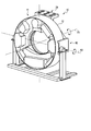
- FIG. 2 is a schematic perspective view of the gantry of FIG.
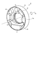
- FIG. 3 is a schematic perspective view of the gantry rotating unit of FIG. 2.
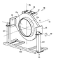
- FIG. 4 is a schematic perspective view of the gantry fixing portion of FIG.
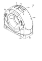
- FIG. 5 is a perspective view showing an appearance of the gantry of FIG. 6 is a schematic plan view of the gantry of FIG. 1 as viewed from the front.
- FIG. 7 is a schematic plan view of the gantry of FIG. 1 as viewed from the front, in which the air flow is indicated by arrows.
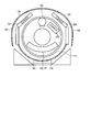
- FIG. 8 is a schematic plan view of the gantry of FIG.
- FIG. 9 is a schematic plan view of a conventional gantry viewed from the front.
- FIG. 10 is a schematic plan view in which an air flow is indicated by an arrow when a gantry according to a conventional example is viewed from the front.
- FIG. 1 is a diagram showing a configuration of an X-ray computed tomography apparatus 1 according to the present embodiment. As shown in FIG. 1, the X-ray computed tomography apparatus 1 includes a gantry 10 and a console 40.
- the gantry 10 is equipped with a gantry rotating unit 11 in a cover in which an opening 11a is formed.
- the gantry rotating unit 11 is equipped with an X-ray tube 13 and an X-ray detector 15 that are arranged to face each other.
- An FOV field of view
- the gantry rotating unit 11 is electrically connected to the rotation driving unit 19.
- the rotation driving unit 19 rotates the gantry rotating unit 11 at a constant angular velocity according to the control by the gantry control unit 21.
- An angle detector 23 such as a rotary encoder is attached to the rotation drive unit 19.
- the angle detector 23 repeatedly generates an electric pulse signal (hereinafter referred to as an angle signal) corresponding to an angle around the rotation axis R1 of the gantry rotating unit 11 every time the gantry rotating unit 11 rotates by a certain angle.
- the angle signal is supplied to the gantry control unit 21.
- the uppermost part is 0 ° and the lowermost part is 180 °.
- the angle around the rotation axis R1 of the gantry rotating unit 11 when the rotation is stopped is called a home position.
- the X-ray tube 13 receives an application of a high voltage from the high voltage generator 25 and generates X-rays.
- the high voltage generator 25 applies a high voltage to the X-ray tube 13 according to the control by the gantry controller 21.
- an X-ray tube cooling device (oil cooler) 27 and a cooling fan 29 are provided inside the gantry 10.
- the oil cooler 27 is cooled by circulating oil to and from the X-ray tube 13 in accordance with control from the gantry control unit 21.
- the cooling fan 29 is an exhaust fan that sends air inside the gantry 10 to the outside in accordance with control from the gantry controller 21.
- the X-ray detector 15 detects X-rays generated from the X-ray tube 13.
- the X-ray detector 15 is equipped with a plurality of X-ray detection elements arranged in a two-dimensional shape.
- the plurality of X-ray detection elements are arranged along an arc centered on the rotation axis R ⁇ b> 1 of the gantry rotating unit 11.
- the arrangement direction of the X-ray detection elements along the arc is called a channel direction.
- a plurality of X-ray detection elements arranged along the channel direction is called an X-ray detection element array.
- the plurality of X-ray detection element rows are arranged along the row direction along the rotation axis R1.
- Each X-ray detection element detects X-rays generated from the X-ray tube 13 and generates an electric signal (current signal) corresponding to the detected X-ray intensity.
- the generated electrical signal is supplied to a data collection unit (DAS) 31.
- DAS data collection unit
- the data collection unit 31 collects electrical signals for each view via the X-ray detector 15 under the control of the gantry control unit 21.
- the view corresponds to the rotation angle of the gantry rotating unit 11 around the rotation axis R1.
- the view corresponds to a data sampling point when the gantry rotating unit 11 is rotated.
- the data collecting unit 31 converts the collected analog electric signal into digital data. Digital data is called raw data.
- the raw data is supplied to the console 40 for each predetermined view by the non-contact type transmission unit 33.
- the gantry control unit 21 supervises the control of various devices mounted on the gantry 10 according to instructions from the system control unit 51 in the console 40.
- the gantry control unit 21 controls the rotation drive unit 19, the high voltage generation unit 25, the oil cooler 27, the cooling fan 29, and the data collection unit 31.
- the console 40 includes a preprocessing unit 41, a reconstruction unit 43, a display unit 45, an operation unit 47, a storage unit 49, and a system control unit 51.
- the preprocessing unit 41 performs preprocessing such as logarithmic conversion and sensitivity correction on the raw data transmitted from the transmission unit 33.
- the raw data that has been preprocessed is called projection data.
- the reconstruction unit 43 reconstructs image data related to the subject based on the projection data.
- the display unit 45 displays the image data generated by the reconstruction unit 43 on a display device.
- the operation unit 47 receives various commands and information input from the user by the input device.
- the storage unit 49 stores raw data, projection data, and image data.
- the storage unit 49 stores a control program.
- the system control unit 51 reads out the control program stored in the storage unit 49 and expands it on the memory, and controls each unit according to the expanded control program.
- FIG. 2 is a schematic perspective view of the gantry 1.
- the gantry 10 with the cover removed is shown.
- the gantry 10 includes a gantry rotating unit 11 and a gantry fixing unit 60.
- FIG. 3 is a schematic perspective view of the gantry rotating unit 11, and
- FIG. 4 is a schematic perspective view of the gantry fixing unit 60.
- the gantry rotating part 11 has a substantially cylindrical rotating frame 12 having an opening 11a formed in the center. Holes for attaching various devices such as the X-ray tube 13, the X-ray detector 15, the high voltage generator 25, the oil cooler 27, the cooling fan 29, the data collection unit 31, and the transmission unit 33 to the rotating frame 12. A recess is formed.
- the rotating frame 12 is a metal frame formed of a metal such as aluminum.
- Various devices such as the X-ray tube 13, the X-ray detector 15, the high voltage generation unit 25, the oil cooler 27, the cooling fan 29, the data collection unit 31, and the transmission unit 33 are mounted on the mount fixing unit 60. The power supply is operated from the unit 21 (not shown).
- the X-ray tube 13 and the X-ray detector 15 are attached to the rotary frame 12 so as to face each other across the opening 11a.
- the oil cooler 27 is connected to the X-ray tube 13 through an oil flow path (not shown). The oil circulates between the X-ray tube 13 and the oil cooler 27 through this flow path.
- the oil cooler 27 sucks the oil heated by the X-ray tube 13, cools the sucked oil, and supplies the cooled oil to the X-ray tube 13 through the flow path.
- the oil cooler 27 cools the X-ray tube 13 by circulating oil.
- the oil cooler 27 is provided with an intake port (hereinafter referred to as an oil cooler intake port), an exhaust port (hereinafter referred to as an oil cooler exhaust port), and a fan (hereinafter referred to as an oil cooler cooling fan). It has been.
- the oil cooler 27 sucks up the air inside the gantry 10 by the oil cooler cooling fan, and sucks the sucked up air from the oil cooler intake port.
- the oil cooler 27 is cooled by the sucked air.
- the air sucked by the oil cooler 27 is discharged into the gantry 10 from the oil cooler exhaust port.
- the gantry fixing unit 60 includes a main frame 61, a base stand 63, and a gantry arm 65.
- the main frame 61 rotatably supports the gantry rotating unit 11 around the rotation axis R1.
- the main frame 61 is a metal frame formed of a metal such as aluminum.
- An opening 61 a is formed at the center of the main frame 61.
- a slip ring mechanism (not shown) is attached to the inner peripheral side of the edge 61 b of the opening 61 a in the main frame 61.
- the main frame 61 and the rotary frame 12 are rotatably connected via a bearing or the like. Electric power is supplied to various devices of the gantry rotating unit 11 via a slip ring mechanism.
- the base stand 63 is installed on the floor of the CT imaging room.
- the base stand 63 supports the main frame 61 away from the floor surface.
- the base stand 63 includes, for example, two standing frames 631 and a connection frame 633.
- the two standing frames 631 are attached to both side surfaces of the main frame 61 and are installed upright on the floor surface.
- the connection frame 633 connects the two standing frames 631 in order to strengthen the support of the main frame 61 by the two standing frames 631.
- the base stand 63 is made of a metal such as aluminum.
- the two gantry arms 65 support the main frame 61 so as to be able to tilt (tilt) about a horizontal axis R2 orthogonal to the rotation axis R1 and parallel to the floor surface. Since the two gantry arms 65 are arranged so that the gantry rotating portion 11 intersects the horizontal axis R2, the main frame 61 supports the main frame 61 so as to be separated from the horizontal axis R2 in the direction of the rotation axis R1. Each gantry arm 65 is attached to the upper part of the base stand 63 and couples the base stand 63 and the main frame 61.
- the gantry arm 65 tilts the main frame 61 in response to a drive signal supplied from a drive device (not shown) in the cover.
- the gantry arm 65 is formed of a metal such as aluminum.
- FIG. 5 is a perspective view showing the external appearance of the gantry 10.
- the gantry rotating part 11 and the gantry fixing part 60 are covered with a cover 70.
- the cover 70 includes an upper cover 70-1, a right side cover 70-2, a left side cover 70-3, a bottom cover 70-4, and a lower cover 70-5.
- a plurality of openings (hereinafter referred to as discharge openings) 71 for discharging the air inside the gantry are limited to the local region RL of the cover 70.
- the local area AL is provided at a position shifted along the rotation axis R1 from the area facing the outer periphery of the gantry rotating portion 11 in the upper cover 70-1.
- the discharge opening 71 is provided at a position shifted along the rotation axis R1 from a region facing the outer periphery of the gantry rotating unit 11 in the upper cover 70-1.
- the local region RL is a single region including a 0 ° position, as shown in FIG.
- the plurality of discharge openings 71 are formed in the upper cover 70-1.
- the lower cover 70-5 is attached to prevent the bottom portion of the gantry rotating unit 11 from being seen from the outside when the gantry rotating unit 11 is tilted about the horizontal axis R2.
- a plurality of intake openings (hereinafter referred to as intake openings, not shown in FIG. 5) are formed in the lower cover 70-5. Outside air having a temperature lower than that of the air inside the gantry is sucked into the gantry 10 through a plurality of intake openings. The air inside the gantry 10 is discharged from the plurality of discharge openings 71.
- the air inside the gantry 10 can be discharged from the plurality of discharge openings 71 by the oil cooler cooling fan.
- the temperature inside the gantry 10 is spatially uniform, and the air inside the gantry 10 cannot be discharged from the plurality of discharge openings 71 only by the oil cooler cooling fan. Therefore, as shown in FIGS. 2 and 4, a plurality of cooling fans 29 are attached to the main frame 61 separately from the oil cooler cooling fan. The plurality of cooling fans 29 are arranged in the vicinity of the plurality of discharge openings 71 in order to increase the discharge efficiency of the air inside the gantry 10.
- the plurality of discharge openings 71 and the plurality of cooling fans 29 are attached at substantially the same angular position. As described above, when the plurality of discharge openings 71 are provided at the uppermost portion of the cover 70, the plurality of cooling fans 29 are disposed immediately below the plurality of discharge openings 71. Typically, one cooling fan 29 is provided for one discharge opening 71.
- the plurality of discharge openings 71 are provided in a mounting plate 67 provided in the main frame 61, for example.
- the mounting plate 67 extends in the direction opposite to the gantry rotating unit 11 along the rotation axis R1.
- the mounting plate 67 may be formed separately from the main frame 61 or may be formed integrally.
- the discharge opening 71 can be arranged in the direction opposite to the arrangement position of the gantry rotating part 11 along the rotation axis R ⁇ b> 1 from directly above the gantry rotating part 11. That is, the discharge opening 71 is arranged at a position shifted from the outer periphery of the gantry rotating unit 11.
- This structure makes it possible to bring the overall diameter of the gantry 10 closer to the diameter of the rotating frame 12 compared to the conventional case in which the cooling fan 29 is provided on the outer periphery of the gantry rotating unit 11. can do.
- a very large noise is generated by the rotation of the gantry rotating unit 11 and the driving of the oil cooler 27.
- the plurality of discharge openings 71 according to this embodiment are the main sound source, the gantry rotating unit 11 and the oil cooler 27, as compared with the conventional example in which a plurality of discharge openings are formed on the outer periphery of the gantry rotating unit. Is relatively far from Therefore, in the gantry 10 according to the present embodiment, noise during the gantry rotation is reduced as compared with the conventional one.
- the gantry controller 21 arranges the oil cooler 27 at a substantially 0 ° position when the gantry rotating unit 11 stops rotating.
- the positioning control of the oil cooler 27 will be described.
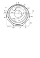
- FIG. 6 is a schematic plan view of the gantry 10 as viewed from the front.
- a plurality of exhaust openings 71 and a plurality of cooling fans 29 are collectively provided at the 0 ° position.
- the plurality of exhaust openings 71 are formed in a local region located at the top of the upper cover 70-1.
- the plurality of cooling fans 29 are attached to the main frame 61 in the vicinity of the plurality of exhaust openings 71. In other words, the plurality of cooling fans 29 are arranged at approximately 0 ° positions.
- the oil cooler 27 is disposed at a substantially 0 ° position.
- the X-ray detector 15 is disposed at a position deviated from approximately 180 °.
- a lower cover 70-5 is attached below the rotating frame 12 of the gantry rotating unit 11 so as to cover the gantry rotating unit 11.
- An intake opening 73 is formed in the lower cover 70-5.
- the gantry control unit 21 controls the rotation driving unit 19 to stop the rotation of the gantry rotating unit 11 in response to an instruction to stop the rotation of the gantry 10.
- the rotation stop instruction may be issued manually by the user via the operation unit 47, or may be automatically issued from the system control unit 51 according to the scan sequence.
- the gantry control unit 21 controls the rotation driving unit 19 so that the reference position of the oil cooler 27 stops at 0 °.
- the reference position of the oil cooler 27 can be set to an arbitrary position such as a center point or an end point in the circumferential direction around the rotation axis R1 of the oil cooler 27, for example.
- the oil cooler 27 is stopped at 0 °, as shown in FIG. 6, the X-ray tube 13 is disposed at a position deviated from 0 °, and the X-ray detector 15 is stopped at a position deviated from 180 °. It will be.
- a right pedestal arm 65 is disposed between the right side cover 70-2 and the rotary frame 12, and a left pedestal arm is provided between the left side cover 70-3 and the rotary frame 12. 65 is arranged.
- the gantry arm 65 according to the present embodiment has an arc shape that follows the outer peripheral shape of the rotating frame 12. As a result, it is possible to reduce the space between the side covers 70-2 and 70-3 and the rotary frame 12 as much as possible, and thus the outer size of the gantry 10 can be reduced. Further, as described later, by narrowing the space between the side covers 70-2 and 70-3 and the rotary frame 12 as much as possible, it is possible to make it difficult for air to flow through this space.
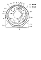
- FIG. 7 is a schematic plan view of the gantry 10 as viewed from the front, in which the air flow is indicated by arrows.
- FIG. 8 is a schematic plan view of the gantry 10 as seen from above the side surface, in which the air flow is indicated by arrows. 7 and 8, the air flow is indicated by arrows.
- the flow path inside the gantry 10 is roughly divided into three.
- the first flow path (solid arrow) first passes through the X-ray detector 15 and the data collection unit 31, rises along the opening 11 a, and reaches the oil cooler inlet of the oil cooler 27. It is.
- the second flow path (dotted arrow) is a flow path that rises along the side covers 73 and 75 between the side surface of the rotating frame 12 and the gantry fixing portion 60 or in the vicinity thereof.
- the gap between the rotary frame 12 and the side covers 73 and 75 is designed to be as narrow as possible by making the gantry arm 65 into an arc shape or the like. That is, the second flow path is narrower than the first flow path.
- the third flow path (dashed line arrow) is a flow path that rises through the gap between the back surface of the rotating frame 12 and the main frame 61. From the viewpoint of downsizing the gantry, the gap between the rotating frame 12 and the main frame 61 is designed to be minimum so that the rotating frame 12 and the main frame 61 do not interfere with each other. Therefore, the third flow path is also narrower than the first flow path.
- the second flow path and the third flow path are designed to be narrow as air flow paths. For this reason, the most main flow path among the flow paths constructed in the gantry 10 is the first flow path.
- the X-ray detector 15 and the data collection unit 31 can be efficiently cooled.
- the air that has risen through the first flow path is sucked upward by the oil cooler cooling fan at the oil cooler intake port of the oil cooler 27 and discharged from the oil cooler exhaust port to the top.
- the discharged air is immediately discharged to the outside of the gantry 10 by a cooling fan 29 disposed in the vicinity of the oil cooler 27.
- the gantry 10 has a structure in which a plurality of exhaust openings 71 and a plurality of cooling fans 29 are integrated in one place. Due to this structure, the gantry 10 limits the air discharge location to one location, unlike the conventional example in which the exhaust openings 71 and the cooling fan 29 are dispersed in a plurality of locations. Typically, the plurality of exhaust openings 71 and the plurality of cooling fans 29 are provided at the top of the gantry 10 where air is most concentrated and easily discharged. When the rotation of the gantry rotating unit 11 is stopped, the oil cooler 27 is disposed in the vicinity of the installation location of the plurality of exhaust openings 71 and the plurality of cooling fans 29.
- the plurality of exhaust openings 71 are provided at positions offset from the outer periphery of the gantry rotating unit 11 toward the main frame 61 from the viewpoint of downsizing the gantry. Thereby, the exhaust opening 71 can be separated from the gantry rotating part 11 and the oil cooler 27 which are main noise sources without reducing the cooling efficiency. As a result, noise suppression is realized. Further, along with the size reduction of the gantry due to the optimum structure and arrangement of each component of the gantry 10, most of the air sucked into the gantry 10 can be flowed to the first flow path.
- the first flow path passes through the inside of the gantry rotating unit 11 equipped with most of the main heat sources of the components included in the gantry 10. Further, the X-ray detector 15 is displaced from the position of about 180 °. Therefore, the gantry 10 can positively send air into the upper part of the X-ray detector 15 and the data collection unit 31 where the stagnation point of air has been generated in the conventional example. As a result, the cooling efficiency can be improved while the scale of the gantry is reduced.
- the plurality of exhaust openings 71 and the plurality of cooling fans 29 are provided on the gantry 10.
- this embodiment is not limited to this.
- a single exhaust opening 71 may be provided in a local region of the cover 70, and a single exhaust opening 71 in the main frame 61 may be provided in the vicinity of the single exhaust opening 71.
- the cooling fan 29 may be provided.
- the plurality of exhaust openings 71 and the plurality of cooling fans 29 are specifically provided at 0 ° positions. However, this embodiment is not limited to this. For example, if there is no problem in cooling efficiency, the plurality of exhaust openings 71 and the plurality of cooling fans 29 may be provided at any position other than the 0 ° position.
- the plurality of exhaust openings 71 and the plurality of cooling fans 29 are provided at positions shifted to the main frame 61 side from the outer periphery of the gantry rotating unit 11.
- this embodiment is not limited to this.
- the plurality of exhaust openings 71 and the plurality of cooling fans 29 may be provided at positions shifted from the outer periphery of the gantry rotating unit 11 to the opposite side of the main frame 61 side.
- SYMBOLS 1 ... X-ray computed tomography apparatus, 10 ... Mount, 11 ... Mount rotating part, 12 ... Rotating frame, 13 ... X-ray tube, 15 ... X-ray detector, 17 ... Top plate, 19 ... Rotation drive part, 21 ... Base control unit, 23 ... Angle detector, 25 ... High voltage generation unit, 27 ... X-ray tube cooling device (oil cooler), 29 ... Cooling fan, 31 ... Data collection unit (DAS), 33 ... Transmission unit, 40 ... Console, 41 ... Pre-processing unit, 43 ... Reconstruction unit, 45 ... Display unit, 47 ... Operation unit, 49 ... Storage unit, 51 ... System control unit, 60 ...
- Mounting stand fixing unit 61 ... Main frame, 63 ... Base stand , 65 ... Fixing arm, 67 ... Placing plate, 70 ... Cover, 70-1 ... Top cover, 70-2 ... Right side cover, 70-3 ... Left side cover, 70-4 ... Bottom cover, 70-5 ... Lower cover, 71 ... exhaust opening, 73 ... Care for the opening, RL ... local area
Landscapes
- Health & Medical Sciences (AREA)
- Life Sciences & Earth Sciences (AREA)
- Engineering & Computer Science (AREA)
- Medical Informatics (AREA)
- Radiology & Medical Imaging (AREA)
- Molecular Biology (AREA)
- Biophysics (AREA)
- Nuclear Medicine, Radiotherapy & Molecular Imaging (AREA)
- Optics & Photonics (AREA)
- Pathology (AREA)
- Physics & Mathematics (AREA)
- Biomedical Technology (AREA)
- Heart & Thoracic Surgery (AREA)
- High Energy & Nuclear Physics (AREA)
- Surgery (AREA)
- Animal Behavior & Ethology (AREA)
- General Health & Medical Sciences (AREA)
- Public Health (AREA)
- Veterinary Medicine (AREA)
- Pulmonology (AREA)
- Theoretical Computer Science (AREA)
- Apparatus For Radiation Diagnosis (AREA)
Priority Applications (1)
| Application Number | Priority Date | Filing Date | Title |
|---|---|---|---|
| US14/730,945 US9247917B2 (en) | 2012-12-04 | 2015-06-04 | X-ray computed tomography apparatus |
Applications Claiming Priority (4)
| Application Number | Priority Date | Filing Date | Title |
|---|---|---|---|
| JP2012-265648 | 2012-12-04 | ||
| JP2012265648 | 2012-12-04 | ||
| JP2013-250907 | 2013-12-04 | ||
| JP2013250907A JP6334905B2 (ja) | 2012-12-04 | 2013-12-04 | X線コンピュータ断層撮影装置 |
Related Child Applications (1)
| Application Number | Title | Priority Date | Filing Date |
|---|---|---|---|
| US14/730,945 Continuation US9247917B2 (en) | 2012-12-04 | 2015-06-04 | X-ray computed tomography apparatus |
Publications (1)
| Publication Number | Publication Date |
|---|---|
| WO2014088041A1 true WO2014088041A1 (ja) | 2014-06-12 |
Family
ID=50883458
Family Applications (1)
| Application Number | Title | Priority Date | Filing Date |
|---|---|---|---|
| PCT/JP2013/082628 Ceased WO2014088041A1 (ja) | 2012-12-04 | 2013-12-04 | X線コンピュータ断層撮影装置 |
Country Status (3)
| Country | Link |
|---|---|
| US (1) | US9247917B2 (enExample) |
| JP (1) | JP6334905B2 (enExample) |
| WO (1) | WO2014088041A1 (enExample) |
Cited By (1)
| Publication number | Priority date | Publication date | Assignee | Title |
|---|---|---|---|---|
| CN105530751A (zh) * | 2016-01-22 | 2016-04-27 | 上海联影医疗科技有限公司 | Ct设备的散热结构 |
Families Citing this family (9)
| Publication number | Priority date | Publication date | Assignee | Title |
|---|---|---|---|---|
| US10039505B2 (en) * | 2014-07-22 | 2018-08-07 | Samsung Electronics Co., Ltd. | Anatomical imaging system having fixed gantry and rotating disc, with adjustable angle of tilt and increased structural integrity, and with improved power transmission and position sensing |
| DE102014226467B4 (de) * | 2014-12-18 | 2023-06-15 | Siemens Healthcare Gmbh | Medizinische Bildgebungsvorrichtung mit einem Rahmenelement zur Anordnung einer Komponente |
| JP6618304B2 (ja) * | 2015-06-30 | 2019-12-11 | キヤノン株式会社 | 乳房撮影装置 |
| KR101733798B1 (ko) * | 2015-08-11 | 2017-05-10 | 삼성전자주식회사 | 냉각 ct 시스템 |
| DE102017208955A1 (de) * | 2017-05-29 | 2018-11-29 | Siemens Healthcare Gmbh | Detektorvorrichtung aufweisend einen Kühlluftpfad zum Kühlen eines Röntgendetektors |
| US11389126B2 (en) * | 2018-10-31 | 2022-07-19 | General Electric Company | Gantry housing, and medical apparatus |
| CN112826517A (zh) * | 2019-11-22 | 2021-05-25 | 德瑞科(天津)机械制造有限公司 | 用于ct探测器的散热装置及ct设备 |
| US11613895B2 (en) * | 2020-08-14 | 2023-03-28 | Frameless Hardware Company Llc | Panel securing system and method |
| CN115886851A (zh) * | 2022-09-02 | 2023-04-04 | 上海西门子医疗器械有限公司 | Ct支架、ct机架和ct设备 |
Citations (2)
| Publication number | Priority date | Publication date | Assignee | Title |
|---|---|---|---|---|
| JPH09313474A (ja) * | 1996-05-30 | 1997-12-09 | Hitachi Medical Corp | X線ct装置 |
| JP2010227382A (ja) * | 2009-03-27 | 2010-10-14 | Toshiba Corp | X線ct装置 |
Family Cites Families (14)
| Publication number | Priority date | Publication date | Assignee | Title |
|---|---|---|---|---|
| JP3403790B2 (ja) | 1994-01-10 | 2003-05-06 | 株式会社東芝 | X線ct装置 |
| US5761269A (en) * | 1995-08-29 | 1998-06-02 | Kabushiki Kaisha Toshiba | X-ray computerized tomography system having cooling features |
| JP2000116644A (ja) * | 1998-10-16 | 2000-04-25 | Toshiba Corp | X線ct装置 |
| US6491428B1 (en) * | 1999-08-30 | 2002-12-10 | Kabushiki Kaisha Toshiba | X-ray computed tomography apparatus |
| JP4564144B2 (ja) | 1999-08-30 | 2010-10-20 | 株式会社東芝 | X線コンピュータトモグラフィ装置 |
| JP2002345804A (ja) | 2001-05-18 | 2002-12-03 | Ge Medical Systems Global Technology Co Llc | X線管ユニット及び装置並びにその冷却方法及びプログラム |
| US6909775B2 (en) * | 2002-12-16 | 2005-06-21 | Ge Medical Systems Global Technology Company, Llc | Computed tomography gantry cooling systems and methods |
| DE10312253B4 (de) * | 2003-03-19 | 2007-04-05 | Siemens Ag | Kühlsystem, Computertomographie-Anlage mit einem solchen Kühlsystem und Verfahren zur Kühlung einer Gantry |
| RU2484773C2 (ru) * | 2007-11-30 | 2013-06-20 | Конинклейке Филипс Электроникс Н.В. | Охлаждение портальной рамы |
| JP5148331B2 (ja) * | 2008-03-14 | 2013-02-20 | 株式会社東芝 | X線ct装置 |
| JP5348940B2 (ja) * | 2008-05-09 | 2013-11-20 | 株式会社東芝 | X線コンピュータ断層撮影装置 |
| JP2010162127A (ja) * | 2009-01-14 | 2010-07-29 | Toshiba Corp | X線ct装置 |
| JP2011143063A (ja) | 2010-01-14 | 2011-07-28 | Toshiba Corp | X線コンピュータ断層撮影装置 |
| JP5159965B1 (ja) * | 2012-02-22 | 2013-03-13 | 株式会社東芝 | X線ct装置 |
-
2013
- 2013-12-04 WO PCT/JP2013/082628 patent/WO2014088041A1/ja not_active Ceased
- 2013-12-04 JP JP2013250907A patent/JP6334905B2/ja active Active
-
2015
- 2015-06-04 US US14/730,945 patent/US9247917B2/en active Active
Patent Citations (2)
| Publication number | Priority date | Publication date | Assignee | Title |
|---|---|---|---|---|
| JPH09313474A (ja) * | 1996-05-30 | 1997-12-09 | Hitachi Medical Corp | X線ct装置 |
| JP2010227382A (ja) * | 2009-03-27 | 2010-10-14 | Toshiba Corp | X線ct装置 |
Cited By (1)
| Publication number | Priority date | Publication date | Assignee | Title |
|---|---|---|---|---|
| CN105530751A (zh) * | 2016-01-22 | 2016-04-27 | 上海联影医疗科技有限公司 | Ct设备的散热结构 |
Also Published As
| Publication number | Publication date |
|---|---|
| JP2014131636A (ja) | 2014-07-17 |
| JP6334905B2 (ja) | 2018-05-30 |
| US20150265232A1 (en) | 2015-09-24 |
| US9247917B2 (en) | 2016-02-02 |
Similar Documents
| Publication | Publication Date | Title |
|---|---|---|
| JP6334905B2 (ja) | X線コンピュータ断層撮影装置 | |
| CN101574265B (zh) | X射线计算断层摄影装置 | |
| US5761269A (en) | X-ray computerized tomography system having cooling features | |
| JP5677940B2 (ja) | X線ct装置 | |
| JP5911213B2 (ja) | X線ct装置 | |
| US20150374322A1 (en) | Detector system for imaging device | |
| JP6750398B2 (ja) | 画像診断用撮影装置 | |
| JP7493944B2 (ja) | X線ct装置 | |
| US20170325764A1 (en) | Gantry of computed tomography (ct) apparatus | |
| CN104274199A (zh) | 用于计算机x 线断层造影仪台架的旋转环 | |
| JP7390192B2 (ja) | X線ct装置 | |
| US20150265230A1 (en) | X-ray computed tomography apparatus | |
| CN117939863B (zh) | 用于医疗影像设备的低噪音控温装置和方法及医疗影像设备 | |
| JP7182400B2 (ja) | X線ct装置 | |
| JP7009244B2 (ja) | X線ct装置及び医用画像診断装置 | |
| US8774352B2 (en) | X-ray CT apparatus | |
| JP2017074361A (ja) | X線コンピュータ断層撮影装置および架台装置 | |
| JP2019180827A (ja) | 医用画像診断装置および架台制御装置 | |
| JP2023147381A (ja) | X線ct装置 | |
| JP7779699B2 (ja) | X線ct装置 | |
| KR20150093427A (ko) | 엑스선 영상장치 | |
| JP6734151B2 (ja) | X線コンピュータ断層撮影装置 | |
| JP2025120583A (ja) | X線ct装置 | |
| JP2006150121A (ja) | X線コンピュータ断層撮影装置 | |
| JP2006116174A (ja) | 撮影装置 |
Legal Events
| Date | Code | Title | Description |
|---|---|---|---|
| 121 | Ep: the epo has been informed by wipo that ep was designated in this application |
Ref document number: 13860124 Country of ref document: EP Kind code of ref document: A1 |
|
| NENP | Non-entry into the national phase |
Ref country code: DE |
|
| 122 | Ep: pct application non-entry in european phase |
Ref document number: 13860124 Country of ref document: EP Kind code of ref document: A1 |