WO2014084002A1 - 電動工具用充電装置 - Google Patents
電動工具用充電装置 Download PDFInfo
- Publication number
- WO2014084002A1 WO2014084002A1 PCT/JP2013/079753 JP2013079753W WO2014084002A1 WO 2014084002 A1 WO2014084002 A1 WO 2014084002A1 JP 2013079753 W JP2013079753 W JP 2013079753W WO 2014084002 A1 WO2014084002 A1 WO 2014084002A1
- Authority
- WO
- WIPO (PCT)
- Prior art keywords
- power
- battery pack
- fuel cell
- charging
- output
- Prior art date
- Legal status (The legal status is an assumption and is not a legal conclusion. Google has not performed a legal analysis and makes no representation as to the accuracy of the status listed.)
- Ceased
Links
Images



Classifications
-
- H—ELECTRICITY
- H02—GENERATION; CONVERSION OR DISTRIBUTION OF ELECTRIC POWER
- H02J—ELECTRIC POWER NETWORKS; CIRCUIT ARRANGEMENTS OR SYSTEMS FOR SUPPLYING OR DISTRIBUTING ELECTRIC POWER; SYSTEMS FOR STORING ELECTRIC ENERGY
- H02J7/00—Circuit arrangements for charging or discharging batteries or for supplying loads from batteries
- H02J7/34—Parallel operation in networks using both storage and other DC sources, e.g. providing buffering
-
- H—ELECTRICITY
- H01—ELECTRIC ELEMENTS
- H01M—PROCESSES OR MEANS, e.g. BATTERIES, FOR THE DIRECT CONVERSION OF CHEMICAL ENERGY INTO ELECTRICAL ENERGY
- H01M16/00—Structural combinations of different types of electrochemical generators
-
- H—ELECTRICITY
- H01—ELECTRIC ELEMENTS
- H01M—PROCESSES OR MEANS, e.g. BATTERIES, FOR THE DIRECT CONVERSION OF CHEMICAL ENERGY INTO ELECTRICAL ENERGY
- H01M2250/00—Fuel cells for particular applications; Specific features of fuel cell system
- H01M2250/30—Fuel cells in portable systems, e.g. mobile phone, laptop
-
- H—ELECTRICITY
- H02—GENERATION; CONVERSION OR DISTRIBUTION OF ELECTRIC POWER
- H02J—ELECTRIC POWER NETWORKS; CIRCUIT ARRANGEMENTS OR SYSTEMS FOR SUPPLYING OR DISTRIBUTING ELECTRIC POWER; SYSTEMS FOR STORING ELECTRIC ENERGY
- H02J2101/00—Supply or distribution of decentralised, dispersed or local electric power generation
- H02J2101/20—Dispersed power generation using renewable energy sources
- H02J2101/30—Fuel cells
-
- Y—GENERAL TAGGING OF NEW TECHNOLOGICAL DEVELOPMENTS; GENERAL TAGGING OF CROSS-SECTIONAL TECHNOLOGIES SPANNING OVER SEVERAL SECTIONS OF THE IPC; TECHNICAL SUBJECTS COVERED BY FORMER USPC CROSS-REFERENCE ART COLLECTIONS [XRACs] AND DIGESTS
- Y02—TECHNOLOGIES OR APPLICATIONS FOR MITIGATION OR ADAPTATION AGAINST CLIMATE CHANGE
- Y02B—CLIMATE CHANGE MITIGATION TECHNOLOGIES RELATED TO BUILDINGS, e.g. HOUSING, HOUSE APPLIANCES OR RELATED END-USER APPLICATIONS
- Y02B90/00—Enabling technologies or technologies with a potential or indirect contribution to GHG emissions mitigation
- Y02B90/10—Applications of fuel cells in buildings
-
- Y—GENERAL TAGGING OF NEW TECHNOLOGICAL DEVELOPMENTS; GENERAL TAGGING OF CROSS-SECTIONAL TECHNOLOGIES SPANNING OVER SEVERAL SECTIONS OF THE IPC; TECHNICAL SUBJECTS COVERED BY FORMER USPC CROSS-REFERENCE ART COLLECTIONS [XRACs] AND DIGESTS
- Y02—TECHNOLOGIES OR APPLICATIONS FOR MITIGATION OR ADAPTATION AGAINST CLIMATE CHANGE
- Y02E—REDUCTION OF GREENHOUSE GAS [GHG] EMISSIONS, RELATED TO ENERGY GENERATION, TRANSMISSION OR DISTRIBUTION
- Y02E60/00—Enabling technologies; Technologies with a potential or indirect contribution to GHG emissions mitigation
- Y02E60/30—Hydrogen technology
- Y02E60/50—Fuel cells
Definitions
- the present invention relates to a power tool charging device that includes a fuel cell and charges the power tool battery pack by output from the fuel cell.
- a charging device that includes a fuel cell is known as a charging device that charges a battery pack for an electric tool (see, for example, Patent Document 1).
- the charging device drives the fuel cell to output DC power and charges the power tool battery pack with the output.
- the battery pack for the electric tool can be charged even when an external power source such as a commercial power source does not exist around.
- the conventional charging device is a dedicated charging device for the power tool battery pack, there is a problem in that power cannot be supplied to electric devices other than the power tool battery pack, and the usability is poor.
- connection terminal is provided in the second DC output unit
- a USB (Universal Serial ⁇ ⁇ Bus) terminal or cigar socket is provided as at least one of the connection terminals as in the power tool charging device of the fourth aspect. Good.
- DC power can be supplied to a USB device that operates by receiving power supply from the USB terminal or an electric device that operates by receiving power supply from the cigar socket.
- the apparatus configuration can be simplified.
- control unit when the control unit outputs the DC power from the second DC output unit to the electric load when the charging from the first DC output unit to the power tool battery pack is stopped, the secondary battery The remaining capacity is detected, and if the detected remaining capacity is less than a predetermined threshold, the fuel cell is driven, and if the remaining capacity is equal to or greater than the threshold, the driving of the fuel cell is stopped.
- both the electric power supply from the 1st DC output part to the battery pack for electric tools and the electric power supply from the 2nd DC output part to the electric load are stopped.
- the driving of the fuel cell is stopped.
- the fuel cell can be driven only when the electric power from the fuel cell is necessary, and the driving efficiency of the fuel cell is improved. This makes it possible to reduce fuel consumption.
- charging to the secondary battery can be performed not only from the fuel cell but also from an external power source. It may be configured so that it can be implemented.
- the secondary battery can be charged from the electric tool battery pack connected to the first DC output unit instead of the fuel cell. Configured.
- the external power supply can be Alternatively, the secondary battery can be charged by supplying power from the power tool battery pack, and the power tool charging device can be returned to the normal state.
- a power tool charging device (hereinafter simply referred to as a charging device) 1 according to the present embodiment connects a battery pack charging terminal 10 for connecting a power tool battery pack to a USB device.
- USB output terminal 12 (hereinafter simply referred to as a charging device) 1 according to the present embodiment connects a battery pack charging terminal 10 for connecting a power tool battery pack to a USB device.
- the fuel cell 14 does not supply the reformed fuel (hydrogen), but directly supplies the liquid fuel (methanol) stored in the fuel tank 16 (direct methanol fuel cell (DMFC) is adopted.
- the output path of the DC power from the fuel cell 14 is branched into two systems, and one output path is connected to the battery pack charging terminal 10 via the battery pack charging control circuit 22 and the other output path. Are connected to the USB output terminal 12 via the USB output control circuit 24.
- the battery pack charge control circuit 22 is for supplying power from the fuel cell 14 and charging the battery pack for the electric tool connected to the battery pack charge terminal 10.
- the battery pack charge control circuit 22 performs charging of the power tool battery pack in accordance with the charge request from the control unit 30.
- the USB output control circuit 24 receives power supply from the fuel cell 14, generates a power supply voltage (DC 5 V) for driving the USB device, and the generated power supply voltage is connected to the USB output terminal 12. It is for output to.
- the USB output control circuit 24 operates in accordance with the output request from the control unit 30.
- generation of the power supply voltage for driving the USB device and the USB device having the power supply voltage are generated. Stops output to.
- the charging device 1 of the present embodiment is provided with a drive battery 32 for supplying a power supply voltage for operation to the fuel adjustment unit 18 and the control unit 30. Since the battery pack charge control circuit 22 is for charging the battery pack for the electric tool, the battery pack charge control circuit 22 is configured to be able to output power of 50 W or more necessary for the charge. Since power is supplied to the USB device, the output power is set to 10 W or less.
- control part 30 is comprised with the microcomputer centering on CPU, ROM, RAM, etc. And the control part 30 detects the connection state of the battery pack to the battery pack charge terminal 10 based on the signal input into the battery pack charge terminal 10 from the control terminal of a battery pack.
- control unit 30 detects the connection state of the USB device to the USB output terminal 12 based on a signal input from the communication terminal of the USB device to the USB output terminal 12.
- control unit 30 outputs a charge request to the battery pack charge control circuit 22 to start charging the battery pack for the electric tool.
- control unit 30 issues a request for charging to the battery pack charging control circuit 22.
- the output is stopped, and charging of the battery pack for the electric power tool is stopped.
- the control unit 30 when a USB device is connected to the USB output terminal 12, the control unit 30 outputs an output request to the USB output control circuit 24 to start supplying power to the USB device, and then from the USB output terminal 12.
- the output request to the USB output control circuit 24 is stopped, and the power supply to the USB device is stopped.
- the control unit 30 determines whether or not the fuel cell 14 is operating, If the battery 14 is not operating, driving of the fuel cell 14 is started via the fuel adjustment unit 18.
- the fuel cell 14 is driven by causing the fuel adjustment unit 18 to supply the fuel in the fuel tank 16 to the fuel cell 14. Thereafter, when both the charging request and output request output to the battery pack charging control circuit 22 and the USB output control circuit 24 are stopped, the control unit 30 stops the fuel supply to the fuel cell by the fuel adjusting unit 18. Then, the driving of the fuel cell 14 is stopped.
- the charging device 1 supplies a power supply voltage to the USB device separately from the battery pack charging control circuit 22 and the battery pack charging terminal 10 for charging the power tool battery pack.
- a USB output control circuit 24 and a USB output terminal 12 are provided.
- control unit 30 drives the fuel cell 14 via the fuel adjustment unit 18 to generate DC power for charging or generating a power supply voltage. Generate.
- the charging device 1 of the present embodiment not only can the battery pack for the electric power tool connected to the battery pack charging terminal 10 be charged, but also power can be supplied to the USB device connected to the USB output terminal 12. It is possible to improve the usability of the charging device 1.
- the driving battery 32 corresponds to an example of the driving power source of the present invention
- the battery pack charging control circuit 22 and the battery pack charging terminal 10 are examples of the first DC output unit of the present invention.
- the USB output control circuit 24 and the USB output terminal 12 correspond to an example of the second DC output unit of the present invention.
- the charging device 2 of the present embodiment is provided with a secondary battery 34, a secondary battery charge control circuit 36, and a display unit 40 with respect to the charging device 1 of the first embodiment.
- a power supply circuit 38 is provided instead of the driving battery 32.
- the charging device 2 of the present embodiment is the same as the charging device 1 of the first embodiment except that the configuration of these units and the operation of the control unit 30 are different from those of the first embodiment. For this reason, in the following description, only a different point from 1st Embodiment is demonstrated, and description is not repeated about the same part as 1st Embodiment.
- the secondary battery 34 and the secondary battery charge control circuit 36 are provided in the output path of DC power from the fuel cell 14 to the battery pack charge control circuit 22 and the USB output control circuit 24. Then, the secondary battery charge control circuit 36 receives power supply from the fuel cell 14 to charge the secondary battery 34, and the secondary battery 34 is converted to the DC power charged via the secondary battery charge control circuit 36. Thus, power is supplied to the battery pack charge control circuit 22 and the USB output control circuit 24.
- the secondary battery 34 functions as a buffer for temporarily storing the output from the fuel cell 14, and stably supplies DC power to the battery pack charge control circuit 22 and the USB output control circuit 24. Used.
- the secondary battery 34 is configured by a chargeable / dischargeable chemical battery, a capacitor, or the like.
- the power supply circuit 38 operates by receiving power supply from the secondary battery 34 and generates a power supply voltage for operating the fuel adjusting unit 18 and the control unit 30.
- the charging device 2 of the first embodiment does not have the secondary battery 34 that is charged by the output from the fuel cell 14, it is necessary to provide the drive battery 32 as a power source for the fuel adjustment unit 18 and the control unit 30. It was.
- the secondary battery 34 since the secondary battery 34 is provided, the secondary battery 34 is used as a power source for the fuel adjustment unit 18 and the control unit 30 without providing the drive battery 32.
- the fuel adjustment unit 18 and the control unit 30 can be operated.
- the display unit 40 displays the remaining capacity that represents the amount of power charged in the secondary battery 34 and the remaining fuel amount that represents the amount of fuel in the fuel tank 16 in accordance with a display command from the control unit 30. Is.
- the user can detect the remaining capacity and the remaining fuel amount of the secondary battery 34 by confirming the display content of the display unit 40. Further, when the remaining capacity of the secondary battery 34 is small, the user drives the fuel cell 14 to charge the secondary battery 34, and when the remaining amount of fuel is small, the user replenishes the fuel tank 16 with fuel. Can do.
- the user cannot discharge the secondary battery 34 due to such an operation to charge the power tool battery pack and supply power to the USB device, or the fuel in the fuel tank 16 runs out. It can be suppressed that the battery 14 cannot be driven.
- control unit 30 determines the battery pack charge control circuit 22 and the USB output control circuit 24 based on the connection state of the battery pack and the USB device to the battery pack charge terminal 10 and the USB output terminal 12.
- the fuel adjusting unit 18 is controlled, and the secondary battery charging control circuit 36 is also controlled.
- the battery pack charging process shown in FIG. 3 is a process that is repeatedly executed as one of the main routines in the control unit 30.
- S100 S represents a step. It is determined whether or not a battery pack is connected to the terminal 10.
- the battery pack charging process is terminated. If the battery pack is connected, the process proceeds to S110, and the battery pack charge control circuit 22 is switched to the power tool battery pack. The charge request is output.
- the secondary battery charge control circuit 36 charges the secondary battery 34.
- the secondary battery 34 is charged by the output from the fuel cell 14 via the secondary battery charge control circuit 36 and is connected to the battery pack charge terminal 10 via the battery pack charge control circuit 22. It will be discharged to the pack side.
- S140 it is determined whether or not the battery pack is disconnected from the battery pack charging terminal 10 (in other words, whether or not the battery pack has been removed). If the battery pack has not been removed, S150 is determined. Then, it is determined whether or not the power tool battery pack is fully charged.
- the charging of the power tool battery pack is stopped by stopping the output of the charging request to the battery pack charging control circuit 22.
- the USB output control circuit 24 determines whether power is being supplied to the USB device connected to the USB output terminal 12.
- the battery pack charging process is terminated as it is. On the other hand, if the USB output control circuit 24 is not supplying power to the USB device, the process proceeds to S180, and the charging request to the secondary battery charging control circuit 36 is stopped to charge the secondary battery 34. Stop.
- the fuel adjustment unit 18 stops the fuel supply to the fuel cell 14 to stop the operation of the fuel cell 14, and then the battery pack charging process is terminated.
- the USB device output process shown in FIG. 4 is a process started when a USB device is connected to the USB output terminal 12 (when connection is detected). Also, the USB device output stop process shown in FIG. 4 is a process that is started when the connection of the USB device to the USB output terminal 12 is released (when release is detected).
- the USB output control circuit 24 outputs a power supply voltage output request to the USB device to the USB output terminal 12. Power supply to the connected USB device is started.
- the battery pack charge control circuit 22 determines whether or not the battery pack for the electric tool is being charged. If the battery pack is being charged, the USB device output process is terminated as it is, and the battery pack is being charged. If not, the process proceeds to S220.
- the remaining capacity of the secondary battery 34 is detected, and it is determined whether or not the remaining capacity is less than a threshold value C1 (for example, 30%) with respect to the amount of power when fully charged. That is, the power consumption of the USB device is extremely small compared to the power required for charging the battery pack for the power tool. If the remaining capacity of the secondary battery 34 is equal to or greater than the threshold value C1, it is stored in the secondary battery 34. The amount of power supply to the USB device can be performed only with the remaining power.
- a threshold value C1 for example, 30%
- the process proceeds to S230, and if not, the process of S220 is performed again to perform the secondary process. A decrease in the remaining capacity of the battery 34 is monitored.
- the remaining capacity of the secondary battery 34 is calculated based on the voltage of the secondary battery 34 or the integrated value of charge / discharge current to the secondary battery 34.
- a request for charging the secondary battery 34 is output to the secondary battery charge control circuit 36, and in S240, fuel supply to the fuel cell 14 is started by the fuel adjusting unit 18 to thereby start the fuel cell. 14 is operated.
- the process proceeds to S250, and it is determined whether or not the secondary battery 34 is fully charged by the charging. This determination is made based on the voltage or charging current of the secondary battery 34.
- the determination process of S250 is repeatedly executed until the secondary battery 34 is fully charged. When the secondary battery 34 is fully charged, the process proceeds to S260. In S260, the battery pack charge control circuit 22 determines whether or not the battery pack for the electric tool is being charged. If the battery pack is being charged, the USB device output process is terminated as it is, and the battery pack must be charging. If so, the process proceeds to S270.
- the charging of the secondary battery 34 is stopped by stopping the output of the charging request to the secondary battery charging control circuit 36.
- the fuel adjustment unit 18 stops the fuel supply to the fuel cell 14 to stop the operation of the fuel cell 14, and then the USB device output process is terminated.
- the secondary battery 34 that is charged by the output from the fuel cell 14 is provided, and the battery pack charge control circuit 22 and the USB output control circuit 24 include DC power is supplied from the secondary battery 34.
- the power to the battery pack and the USB device is compared with the case where direct power is directly supplied from the fuel cell 14 to the battery pack charge control circuit 22 and the USB output control circuit 24. Supply can be performed stably.
- the remaining capacity of the secondary battery 34 is equal to or greater than the threshold value C1.
- the driving of the fuel cell 14 and the charging of the secondary battery 34 are not performed.
- the remaining capacity of the secondary battery 34 is less than the threshold value C1 and the driving of the fuel cell 14 and the charging of the secondary battery 34 are started, thereafter, until the fuel cell 14 is fully charged, The driving of the fuel cell 14 and the charging of the secondary battery 34 are continued.
- the fuel cell 14 can be driven efficiently and the fuel consumption by the fuel cell 14 can be suppressed.
- the display unit 40 corresponds to an example of the notification unit of the present invention.
- the remaining capacity of the secondary battery 34 and the remaining amount of fuel in the fuel tank 16 are displayed on the display unit 40 to notify the user of these parameters.
- one of these, such as the remaining amount of fuel may be displayed.
- the notification (notification) to the user is not limited to the display on the display unit 40.
- the notification may be made by voice according to a request from the user, and the remaining amount of the secondary battery 34 may remain. You may make it notify by generating a warning sound at the time of the fall of a capacity
- the charging device 3 of 3rd Embodiment is demonstrated.
- the charging device 3 of the present embodiment has an AC / AC that converts an AC voltage supplied from an external AC power source (for example, a commercial power source) 42 into a DC voltage.
- a DC converter 44 is provided.
- the output of the AC / DC converter 44 is connected in parallel to the output of the fuel cell 14. Further, the control unit 30 stops the operation of the fuel cell 14 when the AC / DC converter 44 is supplied with power from the external AC power source 42, and the AC / DC converter 44 replaces the fuel cell 14 with DC power. To recharge the secondary battery 34.
- the charging device 3 of the present embodiment if there is an AC power source 42 around the charging device 3, it is used to charge the battery pack for the power tool, supply power to the USB device, and The secondary battery 34 can be charged, and driving of the fuel cell 14 (and hence consumption of fuel) can be suppressed.
- the AC / DC converter 44 may be built in the charging device 3 or may be configured as a separate body from the charging device 3 as a so-called AC adapter. [Fourth Embodiment] Next, the charging device 4 of 4th Embodiment is demonstrated.
- the charging device 4 of the present embodiment charges the secondary battery 34 by receiving power from the battery pack side connected to the battery pack charging terminal 10 to the charging device 2 of the second embodiment.
- the secondary battery charging control circuit 26 is provided.
- the secondary battery charge control circuit 26 is connected in parallel with the battery pack charge control circuit 22, and power is supplied from both the secondary battery 34 and the battery pack for the electric tool connected to the battery pack charge terminal 10. Can be supplied.
- the secondary battery charging control circuit 26 supplies power to the power supply circuit 38 with the supplied power. For this reason, even if the secondary battery 34 is completely discharged and the remaining capacity becomes zero, the battery pack is connected to the battery pack charging terminal 10 and can receive power supply from the battery pack for the electric tool. If possible, the power supply circuit 38 can supply power to the control unit 30 and operate the control unit 30.
- control part 30 performs a battery pack charge process in the procedure shown in FIG. That is, in this embodiment, when the control unit 30 receives power supply from the power circuit 38 and starts the battery pack charging process, and determines in S100 that the battery pack is connected to the battery pack charging terminal 10, The process proceeds to S102.
- S102 it is determined whether or not the remaining capacity of the secondary battery 34 is less than a lower limit C2 (for example, 0%). If it is determined in S102 that the remaining capacity of the secondary battery 34 is less than the lower limit C2, the fuel adjustment unit 18 cannot be driven by the output from the secondary battery 34, and the process proceeds to S104. Then, a charge request is output to the secondary battery charge control circuit 26.
- a lower limit C2 for example, 0%
- the secondary battery charge control circuit 26 starts to charge the secondary battery 34 upon receiving power supply from the power tool battery pack.
- the process proceeds to S106, and the remaining capacity of the secondary battery 34 is set to the set value C3 (however, C3 is C1 ⁇ C3 ⁇ C2). (For example, 10%) or more is determined to wait for the remaining capacity of the secondary battery 34 to reach the set value C3.
- the charging device 5 of this embodiment is similar to the charging device 2 of the second embodiment in that a power path 50 that receives power supply from the power tool battery pack, two switches SW ⁇ b> 1 and SW ⁇ b> 2 are used. And a USB power mode setting unit 46 operated by a person.
- the power supply path 50 has an output terminal (a pair of positive and negative) of DC power (charging power) to the battery pack for the electric tool at the battery pack charging terminal 10 and an input terminal (a pair of positive and negative) of the DC power in the USB output control circuit 24.
- the USB device connected to the USB output terminal 12 can be supplied with power from the power tool battery pack.
- one switch SW2 is provided on the positive-side (or negative-side) path that constitutes the power supply path 50, and is for conducting and blocking the path.
- the other switch SW1 is provided on the positive side (or negative side) of the pair of positive and negative paths from the secondary battery 34 to the USB output control circuit 24, and is used for conducting and blocking the path. Is.
- Each of these switches SW1 and SW2 is constituted by a semiconductor switch or a relay switch.
- the USB power mode setting unit 46 supplies power from the secondary battery 34 in the charging device 5 to the USB device connected to the USB output terminal 12 or power from the battery pack for the electric tool. This is for the user to manually set whether to supply.
- control unit 30 detects that the USB device is connected to the USB output terminal 12 and executes the USB device output process
- the control unit 30 executes the first implementation according to the power mode set by the USB power mode setting unit 46. Whether to execute the same processing as that of the mode is switched.
- the USB power supply mode is changed to a mode in which power is supplied from the power tool battery pack. Determine whether it is set.
- USB power supply mode is set to supply power from the battery pack
- the process proceeds to S330, the switch SW1 is turned off and the switch SW2 is turned on. An output request is output to the control circuit 24, and the USB device output process is terminated.
- the USB output control circuit 24 receives power supply from the power tool battery pack and supplies a voltage to the USB device. (Power supply voltage) is generated. Therefore, power is supplied to the USB device from the power tool battery pack.
- the process proceeds to S320. Then, the switch SW1 is turned on and the switch SW2 is turned off.
- an output request is output to the USB output control circuit 24, and the processes after S210 are executed.
- a power source for supplying power to the USB device is electrically connected from the secondary battery 34 in the charging device 5 to the battery pack charging terminal 10. It can be switched to a battery pack for tools.
- the charging device 5 that can supply power to the USB device from the battery pack for the electric tool by setting the operation mode by the user has been described.
- the power supply to the control unit 30 may be performed from the power tool battery pack by a switch operation by the user.
- the charging device is described as including the USB output terminal 12 that supplies power to the USB device as an output terminal different from the battery pack charging terminal 10.
- other output terminals such as the cigar socket 13 may be provided separately from the USB output terminal 12 or in addition to the USB output terminal 12.
- the charging device that supplies power to a USB device that is an external electrical load has been described.
- the charging device that supplies power to an electrical load built in the charging device can also be applied to the present invention. Can be applied.
Landscapes
- Engineering & Computer Science (AREA)
- Power Engineering (AREA)
- Chemical & Material Sciences (AREA)
- Chemical Kinetics & Catalysis (AREA)
- Electrochemistry (AREA)
- General Chemical & Material Sciences (AREA)
- Charge And Discharge Circuits For Batteries Or The Like (AREA)
- Fuel Cell (AREA)
- Portable Power Tools In General (AREA)
Abstract
電動工具用充電装置は、燃料電池と、燃料電池を駆動するための駆動用電源と、燃料電池から電力供給を受けて、電動工具用電池パックを充電する第1直流出力部と、燃料電池から電力供給を受けて、電動工具用電池パックとは異なる電気負荷に直流電力を出力する第2直流出力部と、燃料電池を駆動する制御部とを備える。
Description
本国際出願は、2012年11月30日に日本国特許庁に出願された日本国特許出願第2012-262629号に基づく優先権を主張するものであり、日本国特許出願第2012-262629号の全内容を参照により本国際出願に援用する。
本発明は、燃料電池を備え、燃料電池からの出力により電動工具用電池パックへの充電を行う電動工具用充電装置に関する。
従来、電動工具用電池パックへの充電を行う充電装置として、燃料電池を備えたものが知られている(例えば、特許文献1参照)。
この充電装置は、充電対象となる電動工具用電池パックが接続されると、燃料電池を駆動することで、直流電力を出力させ、その出力にて電動工具用電池パックを充電する。
この充電装置は、充電対象となる電動工具用電池パックが接続されると、燃料電池を駆動することで、直流電力を出力させ、その出力にて電動工具用電池パックを充電する。
上記従来の充電装置によれば、周囲に商用電源等の外部電源が存在しない場合にも、電動工具用電池パックへの充電を行うことができる。
しかしながら、上記従来の充電装置は、電動工具用電池パック専用の充電装置であるため、電動工具用電池パック以外の電気機器に電力供給を行うことができず、使い勝手が悪いという問題があった。
しかしながら、上記従来の充電装置は、電動工具用電池パック専用の充電装置であるため、電動工具用電池パック以外の電気機器に電力供給を行うことができず、使い勝手が悪いという問題があった。
燃料電池を備えた電動工具用充電装置において、電動工具用電池パック以外の電気機器にも電力供給できるようにすることが本発明の一側面である。
本発明の第1局面における電動工具用充電装置は、燃料電池、燃料電池を駆動するための駆動用電源、及び、燃料電池を駆動する制御部を備える。
また、燃料電池から電力供給を受けて直流電力を出力する直流出力部として、電動工具用電池パックを充電する第1直流出力部と、電動工具用電池パックとは異なる電気負荷に直流電力を出力する第2直流出力部と、を備える。
また、燃料電池から電力供給を受けて直流電力を出力する直流出力部として、電動工具用電池パックを充電する第1直流出力部と、電動工具用電池パックとは異なる電気負荷に直流電力を出力する第2直流出力部と、を備える。
従って、本発明の電動工具用充電装置によれば、電動工具用電池パックを充電することができるだけでなく、電動工具用電池パックとは異なる電気負荷に直流電力を供給することができ、電動工具用充電装置の使い勝手を向上できる。
次に、本発明の第2局面における電動工具用充電装置においては、第2直流出力部が、電気負荷を接続するための接続端子を備える。
このため、第2局面の電動工具用充電装置によれば、電気負荷が電動工具用充電装置に内蔵されていない外部の電気負荷であっても、接続端子を介して直流電力を供給することができ、電動工具用充電装置の用途を広げることができる。
このため、第2局面の電動工具用充電装置によれば、電気負荷が電動工具用充電装置に内蔵されていない外部の電気負荷であっても、接続端子を介して直流電力を供給することができ、電動工具用充電装置の用途を広げることができる。
なお、本発明の電動工具用充電装置は、電動工具用電池パックを充電するためのものであることから、本発明の第3局面では、第2直流出力部は、第1直流出力部に比べて出力電力が小さいことが望ましい。
つまり、このようにすれば、第1直流出力部からの電動工具用電池パックの充電と同時に、第2直流出力部から電気負荷への直流電力の出力を行う場合に、電動工具用電池パックへの充電電力が低下して、充電時間が長くなるのを抑制できる。
また、第2直流出力部に接続端子を設ける場合には、第4局面の電動工具用充電装置のように、接続端子の少なくとも一つとして、USB(Universal Serial Bus)端子若しくはシガーソケットを設けるとよい。
そして、このようにすれば、USB端子から電力供給を受けて動作するUSB機器若しくはシガーソケットから電力供給を受けて動作する電気機器に対して、直流電力を供給することができる。
次に、本発明の第5局面における電動工具用充電装置においては、駆動用電源として、燃料電池からの出力にて充電される二次電池が備えられている。そして、この二次電池は、第1直流出力部、第2直流出力部、及び制御部に電力供給を行う。
このため、第5局面の電動工具用充電装置によれば、燃料電池から出力される直流電力を二次電池に一旦蓄積した後、第1直流出力部、第2直流出力部に供給することができる。
よって、第1直流出力部若しくは第2直流出力部から電動工具用電池パック若しくは他の電気負荷への電力供給をより安定して行うことができる。
また、二次電池に蓄積された直流電力にて、制御部に電源供給を行うことができることから、制御部が燃料電池を駆動するのに必要な電力を供給するための電源を別途設ける必要がなく、装置構成を簡単にすることができる。
また、二次電池に蓄積された直流電力にて、制御部に電源供給を行うことができることから、制御部が燃料電池を駆動するのに必要な電力を供給するための電源を別途設ける必要がなく、装置構成を簡単にすることができる。
また、第5局面の電動工具用充電装置において、制御部は、第1直流出力部による電動工具用電池パックへの充電時、若しくは、第2直流出力部から電気負荷への直流電力の出力時に、燃料電池を駆動する。
また、制御部は、第1直流出力部から電動工具用電池パックへの充電が停止されているときに、第2直流出力部から電気負荷へ直流電力を出力する際には、二次電池の残容量を検出し、その検出した残容量が所定のしきい値未満であれば、燃料電池を駆動し、残容量が前記しきい値以上であれば燃料電池の駆動を停止する。
このため、第5局面の電動工具用充電装置によれば、第1直流出力部から電動工具用電池パックへの電力供給及び第2直流出力部から電気負荷への電力供給が共に停止されているときには、燃料電池の駆動が停止される。
また、第2直流出力部から電気負荷への電力供給が行われる場合であっても、その電力供給を二次電池に蓄積された電力だけで実施できるときには、燃料電池の駆動が停止される。
従って、第5局面の電動工具用充電装置によれば、燃料電池を、燃料電池からの電力が必要なときに限って駆動することができるようになり、燃料電池の駆動効率を高め、燃料電池による燃料の消費量を低減することが可能となる。
また次に、本願発明の第6局面における電動工具用充電装置は、燃料電池の燃料の残量及び二次電池の残容量の少なくとも一方を報知する報知部を備える。
このため、第6局面の電動工具用充電装置によれば、使用者は、報知部からの報知によって燃料電池の燃料の低下、若しくは、二次電池の残容量の低下、を検知することができ、燃料の補充、二次電池の充電、といった対策を実施することができる。
このため、第6局面の電動工具用充電装置によれば、使用者は、報知部からの報知によって燃料電池の燃料の低下、若しくは、二次電池の残容量の低下、を検知することができ、燃料の補充、二次電池の充電、といった対策を実施することができる。
つまり、燃料電池の燃料がない場合や、二次電池が完全に放電した場合には、第1直流出力部若しくは第2直流出力部から電動工具用電池パック若しくは他の電気負荷への電力供給を実施することができなくなるが、第6局面の電動工具用充電装置によれば、報知部からの報知によって、こうした問題が発生するのを抑制できる。
なお、二次電池を備えた電動工具用充電装置においては、本発明の第7局面における電動工具用充電装置のように、二次電池への充電を、燃料電池だけでなく、外部電源からも実施できるように構成するとよい。
また、本発明の第8局面における電動工具用充電装置においては、二次電池への充電を、燃料電池に代えて、第1直流出力部に接続された電動工具用電池パックからも実施できるように構成される。
第8局面の電動工具用充電装置によれば、二次電池が完全放電し、制御部が、燃料電池を駆動して二次電池を充電させることができなくなった場合であっても、外部電源若しくは電動工具用電池パックからの電力供給により二次電池を充電して、電動工具用充電装置を正常状態に復帰させることができる。
また、本発明の第9局面における電動工具用充電装置においては、第2直流出力部への電力供給経路を、燃料電池からの経路に代えて、第1直流出力部に接続された電動工具用電池パックからの経路に切換できるように構成される。
1,2,3,4,5…充電装置、10…電池パック充電端子、12…USB出力端子、14…燃料電池、16…燃料タンク、18…燃料調整部、22…電池パック充電制御回路、24…USB出力制御回路、26…二次電池充電制御回路、30…制御部、32…駆動電池、34…二次電池、36…二次電池充電制御回路、38…電源回路、40…表示部、42…交流電源、44…AC/DCコンバータ、46…USB電源モード設定部、50…電源経路、SW1,SW2…スイッチ。
以下に本発明の実施形態を図面と共に説明する。
[第1実施形態]
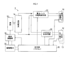
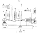
図1に示すように、本実施形態の電動工具用充電装置(以下、単に充電装置という)1は、電動工具用電池パックを接続するための電池パック充電端子10と、USB機器を接続するためのUSB出力端子12と、を備える。
[第1実施形態]
図1に示すように、本実施形態の電動工具用充電装置(以下、単に充電装置という)1は、電動工具用電池パックを接続するための電池パック充電端子10と、USB機器を接続するためのUSB出力端子12と、を備える。
また、充電装置1には、燃料と酸化剤とを酸化反応させることにより直流電力を発生する燃料電池14と、燃料タンク16と、燃料タンク16から燃料電池14へ供給される燃料量を調整する燃料調整部18とが備えられている。
なお、本実施形態では、燃料電池14として、改質後の燃料(水素)を供給するのではなく、燃料タンク16に蓄えられた液体燃料(メタノール)を直接供給する、直接メタノール型燃料電池(DMFC)を採用している。
また、燃料電池14からの直流電力の出力経路は、2系統に分岐されており、一方の出力経路は、電池パック充電制御回路22を介して電池パック充電端子10に接続され、他方の出力経路は、USB出力制御回路24を介してUSB出力端子12に接続されている。
電池パック充電制御回路22は、燃料電池14から電力供給を受けて、電池パック充電端子10に接続された電動工具用電池パックを充電するためのものである。
そして、電池パック充電制御回路22は、制御部30からの充電要求に従い電動工具用電池パックへの充電を実施する。
そして、電池パック充電制御回路22は、制御部30からの充電要求に従い電動工具用電池パックへの充電を実施する。
また、USB出力制御回路24は、燃料電池14から電力供給を受けて、USB機器駆動用の電源電圧(直流5V)を生成し、その生成した電源電圧をUSB出力端子12に接続されたUSB機器に出力するためのものである。
そして、このUSB出力制御回路24は、制御部30からの出力要求に従い動作し、制御部30からの出力要求が停止されると、USB機器駆動用の電源電圧の生成及びその電源電圧のUSB機器への出力を停止する。
また、本実施形態の充電装置1には、燃料調整部18及び制御部30に動作用の電源電圧を供給するための駆動電池32が設けられている。
なお、電池パック充電制御回路22は、電動工具用電池パックを充電するものであるため、その充電に必要な50W以上の電力を出力可能に構成されており、USB出力制御回路24は、外部のUSB機器に電力供給を行うものであるため、出力電力は10W以下に設定されている。
なお、電池パック充電制御回路22は、電動工具用電池パックを充電するものであるため、その充電に必要な50W以上の電力を出力可能に構成されており、USB出力制御回路24は、外部のUSB機器に電力供給を行うものであるため、出力電力は10W以下に設定されている。
次に、制御部30は、CPU、ROM、RAM等を中心とするマイコンにて構成されている。
そして、制御部30は、電池パック充電端子10への電池パックの接続状態を、電池パックの制御端子から電池パック充電端子10に入力される信号に基づき検出する。
そして、制御部30は、電池パック充電端子10への電池パックの接続状態を、電池パックの制御端子から電池パック充電端子10に入力される信号に基づき検出する。
また、制御部30は、USB出力端子12へのUSB機器の接続状態を、USB機器の通信端子からUSB出力端子12に入力される信号に基づき検出する。
そして、制御部30は、電池パック充電端子10に電池パックが接続されると、電池パック充電制御回路22に充電要求を出力して、電動工具用電池パックへの充電を開始させる。
そして、制御部30は、電池パック充電端子10に電池パックが接続されると、電池パック充電制御回路22に充電要求を出力して、電動工具用電池パックへの充電を開始させる。
また、その後、電動工具用電池パックへの充電が完了するか、電池パック充電端子10から電動工具用電池パックが外されると、制御部30は、電池パック充電制御回路22への充電要求の出力を停止して、電動工具用電池パックへの充電を停止させる。
また、制御部30は、USB出力端子12にUSB機器が接続されると、USB出力制御回路24に出力要求を出力して、USB機器への電源供給を開始させ、その後、USB出力端子12からUSB機器が外されると、USB出力制御回路24への出力要求を停止して、USB機器への電源供給を停止させる。
また、制御部30は、電池パック充電端子10に電池パックが接続されるか、USB出力端子12にUSB機器が接続されると、燃料電池14が動作しているか否かを判断して、燃料電池14が動作していなければ、燃料調整部18を介して燃料電池14の駆動を開始する。
なお、燃料電池14の駆動は、燃料調整部18に対し、燃料タンク16内の燃料を燃料電池14に供給させることにより行われる。
そして、その後、電池パック充電制御回路22及びUSB出力制御回路24への充電要求及び出力要求の出力を共に停止すると、制御部30は、燃料調整部18による燃料電池への燃料供給を停止させることで、燃料電池14の駆動を停止する。
そして、その後、電池パック充電制御回路22及びUSB出力制御回路24への充電要求及び出力要求の出力を共に停止すると、制御部30は、燃料調整部18による燃料電池への燃料供給を停止させることで、燃料電池14の駆動を停止する。
以上説明したように、本実施形態の充電装置1には、電動工具用電池パックを充電するための電池パック充電制御回路22及び電池パック充電端子10とは別に、USB機器に電源電圧を供給するためのUSB出力制御回路24及びUSB出力端子12が備えられている。
そして、電動工具用電池パックへの充電時及びUSB機器への電源供給時には、制御部30が、燃料調整部18を介して燃料電池14を駆動し、充電用或いは電源電圧生成用の直流電力を生成させる。
従って、本実施形態の充電装置1によれば、電池パック充電端子10に接続された電動工具用電池パックを充電することができるだけでなく、USB出力端子12に接続されたUSB機器に電源供給を行うことができ、充電装置1の使い勝手を向上できる。
なお、本実施形態においては、駆動電池32が、本発明の駆動用電源の一例に相当し、電池パック充電制御回路22及び電池パック充電端子10が、本発明の第1直流出力部の一例に相当し、USB出力制御回路24及びUSB出力端子12が、本発明の第2直流出力部の一例に相当する。
[第2実施形態]
次に第2実施形態の充電装置2について説明する。
[第2実施形態]
次に第2実施形態の充電装置2について説明する。
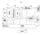
図2に示すように、本実施形態の充電装置2は、第1実施形態の充電装置1に対し、二次電池34と、二次電池充電制御回路36と、表示部40とを設け、更に、駆動電池32に代えて、電源回路38を設けることにより構成されている。
なお、本実施形態の充電装置2は、これら各部の構成及び制御部30の動作が第1実施形態と異なるだけで、他の構成は第1実施形態の充電装置1と同じである。このため、以下の説明では、第1実施形態と異なる点にだけを説明し、第1実施形態と同一部分については説明を重複しない。
二次電池34及び二次電池充電制御回路36は、燃料電池14から、電池パック充電制御回路22及びUSB出力制御回路24への、直流電力の出力経路に設けられている。
そして、二次電池充電制御回路36は、燃料電池14から電力供給を受けて二次電池34を充電し、二次電池34は、二次電池充電制御回路36を介して充電された直流電力にて、電池パック充電制御回路22及びUSB出力制御回路24に電力供給を行う。
そして、二次電池充電制御回路36は、燃料電池14から電力供給を受けて二次電池34を充電し、二次電池34は、二次電池充電制御回路36を介して充電された直流電力にて、電池パック充電制御回路22及びUSB出力制御回路24に電力供給を行う。
つまり、二次電池34は、燃料電池14からの出力を一時的に蓄積するバッファとして機能し、電池パック充電制御回路22及びUSB出力制御回路24に対し、直流電力を安定して供給するのに利用される。
なお、二次電池34は、充放電可能な化学電池やキャパシタ等にて構成されている。
また、電源回路38は、二次電池34から電力供給を受けて動作し、燃料調整部18及び制御部30を動作させるための電源電圧を生成するためのものである。
また、電源回路38は、二次電池34から電力供給を受けて動作し、燃料調整部18及び制御部30を動作させるための電源電圧を生成するためのものである。
つまり、第1実施形態の充電装置2には燃料電池14からの出力により充電される二次電池34がないので、燃料調整部18及び制御部30の電源として、駆動電池32を設ける必要があった。
これに対し、本実施形態では、二次電池34が設けられているので、この二次電池34を燃料調整部18及び制御部30の電源として利用することで、駆動電池32を設けることなく、燃料調整部18及び制御部30を動作させることができるようにしている。
また、表示部40は、制御部30からの表示指令に従い、二次電池34に充電された電力量を表す残容量、及び、燃料タンク16内の燃料量を表す燃料残量を表示するためのものである。
なお、二次電池34の残容量は、二次電池34の満充電時に蓄積される電力量を100%としたときの残電力量の割合を表し、燃料残量は、燃料タンク16に蓄積可能な燃料量を100%としたときの燃料の割合を表す。
従って、使用者は、表示部40の表示内容を確認することで、二次電池34の残容量及び燃料残量を検知することができる。また、使用者は、二次電池34の残容量が少ないときには、燃料電池14を駆動させることで、二次電池34を充電させ、燃料残量が少ないときには、燃料タンク16に燃料を補充することができる。
つまり、使用者は、こうした操作によって、二次電池34が放電して電動工具用電池パックへの充電及びUSB機器への電源供給を行うことができなくなったり、燃料タンク16内の燃料が無くなり燃料電池14を駆動できなくなったりするのを、抑制することができる。
次に、制御部30は、第1実施形態と同様、電池パック充電端子10及びUSB出力端子12への電池パック及びUSB機器の接続状態に基づき、電池パック充電制御回路22、USB出力制御回路24、及び、燃料調整部18を制御し、しかも、二次電池充電制御回路36も制御する。
以下、本実施形態における制御部30の制御動作を、図3及び図4に示すフローチャートに沿って説明する。
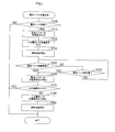
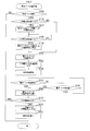
図3に示す電池パック充電処理は、制御部30においてメインルーチンの一つとして繰り返し実行される処理であり、処理が開始されると、まずS100(Sはステップを表す)にて、電池パック充電端子10に電池パックが接続されているか否かを判断する。
図3に示す電池パック充電処理は、制御部30においてメインルーチンの一つとして繰り返し実行される処理であり、処理が開始されると、まずS100(Sはステップを表す)にて、電池パック充電端子10に電池パックが接続されているか否かを判断する。
そして、電池パックが接続されていなければ、当該電池パック充電処理を終了し、電池パックが接続されていれば、S110に移行し、電池パック充電制御回路22に対して、電動工具用電池パックへの充電要求を出力する。
この結果、電池パック充電制御回路22による電動工具用電池パックへの充電が開始される。
次に、S120では、二次電池充電制御回路36に対し、二次電池34への充電要求を出力し、続くS130にて、燃料調整部18による燃料電池14への燃料供給を開始させることで、燃料電池14を動作させる。
次に、S120では、二次電池充電制御回路36に対し、二次電池34への充電要求を出力し、続くS130にて、燃料調整部18による燃料電池14への燃料供給を開始させることで、燃料電池14を動作させる。
つまり、電動工具用電池パックへの充電には、例えば、50W以上の電力が必要であり、二次電池34だけでは電動工具用電池パックを充電するための電力量が不足するので、燃料電池14を動作させて、二次電池充電制御回路36に二次電池34を充電させるのである。
この結果、二次電池34は、二次電池充電制御回路36を介して燃料電池14からの出力により充電されつつ、電池パック充電制御回路22を介して、電池パック充電端子10に接続された電池パック側に放電されることになる。
次にS140では、電池パック充電端子10への電池パックの接続が解除されたか否か(換言すれば、電池パックが取り外されたか否か)を判断し、電池パックが取り外されていなければ、S150に移行して、電動工具用電池パックが満充電になったか否かを判断する。
そして、S150にて、電動工具用電池パックが満充電になっていないと判断されると、S140に移行し、S150にて電動工具用電池パックが満充電になったと判断されるか、或いは、S140にて電池パックが取り外されたと判断されると、S160に移行する。
S160では、電池パック充電制御回路22への充電要求の出力を停止することで、電動工具用電池パックへの充電を停止させる。
次に、S170では、USB出力制御回路24が、USB出力端子12に接続されたUSB機器に電源供給を行っているか否を判断する。
次に、S170では、USB出力制御回路24が、USB出力端子12に接続されたUSB機器に電源供給を行っているか否を判断する。
そして、USB出力制御回路24がUSB機器に電源供給を行っていれば、そのまま当該電池パック充電処理を終了する。
一方、USB出力制御回路24がUSB機器に電源供給を行っていなければ、S180に移行して、二次電池充電制御回路36に対する充電要求の出力を停止することで、二次電池34への充電を停止させる。
一方、USB出力制御回路24がUSB機器に電源供給を行っていなければ、S180に移行して、二次電池充電制御回路36に対する充電要求の出力を停止することで、二次電池34への充電を停止させる。
また、続くS190では、燃料調整部18による燃料電池14への燃料供給を停止させることで、燃料電池14の動作を停止させ、その後、当該電池パック充電処理を終了する。
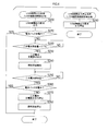
次に、図4に示すUSB機器出力処理は、USB出力端子12にUSB機器が接続されたとき(接続検出時)に起動される処理である。また、図4に示すUSB機器出力停止処理は、USB出力端子12へのUSB機器の接続が解除されたとき(解除検出時)に起動される処理である。
図4に示すように、USB機器出力処理が起動されると、まずS200にて、USB出力制御回路24に対し、USB機器への電源電圧の出力要求を出力することで、USB出力端子12に接続されたUSB機器への電源供給を開始させる。
そして、続くS210では、電池パック充電制御回路22が電動工具用電池パックへの充電中であるか否かを判断し、充電中であれば、そのまま当該USB機器出力処理を終了し、充電中でなければ、S220に移行する。
S220では、二次電池34の残容量を検出し、その残容量が、満充電時の電力量に対し、しきい値C1(例えば30%)未満であるか否かを判断する。
つまり、USB機器の消費電力は、電動工具用電池パックへの充電に要する電力に比べて極めて小さく、二次電池34の残容量がしきい値C1以上であれば、二次電池34に蓄積された電力だけで、USB機器に電源供給量を行うことができる。
つまり、USB機器の消費電力は、電動工具用電池パックへの充電に要する電力に比べて極めて小さく、二次電池34の残容量がしきい値C1以上であれば、二次電池34に蓄積された電力だけで、USB機器に電源供給量を行うことができる。
そこで、S220では、二次電池34の残容量がしきい値C1未満かどうかを判断することで、USB機器への電源供給時に、燃料電池14を動作させて二次電池34を充電する必要があるか否かを判断している。
このため、S220にて、二次電池34の残容量はしきい値C1未満であると判断されると、S230に移行し、そうでなければ、再度S220の処理を実行することで、二次電池34の残容量の低下を監視する。
なお、二次電池34の残容量は、二次電池34の電圧、若しくは、二次電池34への充・放電電流の積算値、に基づき算出される。
S230では、二次電池充電制御回路36に対し、二次電池34への充電要求を出力し、続くS240にて、燃料調整部18による燃料電池14への燃料供給を開始させることで、燃料電池14を動作させる。
S230では、二次電池充電制御回路36に対し、二次電池34への充電要求を出力し、続くS240にて、燃料調整部18による燃料電池14への燃料供給を開始させることで、燃料電池14を動作させる。
このように、S230、S240の処理により、二次電池34への充電が開始されると、S250に移行して、その充電により二次電池34が満充電状態になったか否かを判断する。なお、この判断は、二次電池34の電圧若しくは充電電流に基づき行われる。
S250の判断処理は、二次電池34が満充電状態になるまで繰り返し実行され、二次電池34が満充電状態になると、S260に移行する。
そして、S260では、電池パック充電制御回路22が電動工具用電池パックへの充電中であるか否かを判断し、充電中であれば、そのまま当該USB機器出力処理を終了し、充電中でなければ、S270に移行する。
そして、S260では、電池パック充電制御回路22が電動工具用電池パックへの充電中であるか否かを判断し、充電中であれば、そのまま当該USB機器出力処理を終了し、充電中でなければ、S270に移行する。
S270では、二次電池充電制御回路36に対する充電要求の出力を停止することで、二次電池34への充電を停止させる。
そして、続くS280では、燃料調整部18による燃料電池14への燃料供給を停止させることで、燃料電池14の動作を停止させ、その後、当該USB機器出力処理を終了する。
そして、続くS280では、燃料調整部18による燃料電池14への燃料供給を停止させることで、燃料電池14の動作を停止させ、その後、当該USB機器出力処理を終了する。
従って、電池パックへの充電停止時に、USB出力端子12にUSB機器が接続されてUSB機器への電源供給が開始されると、二次電池34の残容量がしきい値C1未満になれば、燃料電池14が駆動されて、二次電池34が満充電状態になるまで充電されることになる。
一方、USB機器出力停止処理が起動されると、S290にて、USB出力制御回路24に対する出力要求の出力を停止することで、USB機器への電源供給を停止させ、その後、当該USB機器出力停止処理を終了する。
以上説明したように、本実施形態の充電装置2によれば、燃料電池14からの出力にて充電される二次電池34が備えられ、電池パック充電制御回路22及びUSB出力制御回路24には、この二次電池34から直流電力を供給するようにされている。
このため、第1実施形態のように、燃料電池14から電池パック充電制御回路22及びUSB出力制御回路24に直接直流電力を供給するようにした場合に比べて、電池パックやUSB機器への電力供給を安定して行うことができる。
また、本実施形態の充電装置2においては、電動工具用電池パックへの充電停止時に、USB機器への電源供給を開始した際、二次電池34の残容量がしきい値C1以上であれば、燃料電池14の駆動及び二次電池34への充電は実施されない。
また、二次電池34の残容量がしきい値C1未満で、燃料電池14の駆動及び二次電池34への充電を開始した際には、その後、燃料電池14が満充電状態になるまで、燃料電池14の駆動及び二次電池34への充電が継続される。
このため、本実施形態の充電装置2によれば、燃料電池14を効率よく駆動し、燃料電池14による燃料の消費量を抑えることができる。
なお、本実施形態においては、表示部40が、本発明の報知部の一例に相当する。
なお、本実施形態においては、表示部40が、本発明の報知部の一例に相当する。
但し、本実施形態では、表示部40に、二次電池34の残容量、及び、燃料タンク16内の燃料の残量を表示することで、使用者に、これら各パラメータを通知するものとして説明したが、例えば、燃料の残量など、この内の一方を表示するようにしてもよい。
また、使用者への通知(報知)は、表示部40への表示に限定されるものではなく、例えば、使用者からの要求に従い音声により通知するようにしてもよく、二次電池34の残容量の低下時或いは燃料残量の低下時に警告音を発生することで通知するようにしてもよい。また、これらを組み合わせて報知するようにしてもよい。
[第3実施形態]
次に第3実施形態の充電装置3について説明する。
[第3実施形態]
次に第3実施形態の充電装置3について説明する。
図5に示すように、本実施形態の充電装置3は、第2実施形態の充電装置2に、外部の交流電源(例えば商用電源)42から供給される交流電圧を直流電圧に変換するAC/DCコンバータ44を設けることにより構成されている。
そして、このAC/DCコンバータ44の出力は、燃料電池14の出力に並列に接続されている。
また、制御部30は、AC/DCコンバータ44が外部の交流電源42から電源供給を受けているときには、燃料電池14の動作を停止させて、AC/DCコンバータ44を燃料電池14に代わる直流電力の供給源として利用し、二次電池34への充電を行う。
また、制御部30は、AC/DCコンバータ44が外部の交流電源42から電源供給を受けているときには、燃料電池14の動作を停止させて、AC/DCコンバータ44を燃料電池14に代わる直流電力の供給源として利用し、二次電池34への充電を行う。
このため、本実施形態の充電装置3によれば、充電装置3の周囲に交流電源42があれば、それを利用して、電動工具用電池パックへの充電、USB機器への電源供給、及び二次電池34への充電、を行うことができ、燃料電池14の駆動(延いては燃料の消費)を抑制できる。
なお、AC/DCコンバータ44は、充電装置3に内蔵されていてもよく、所謂ACアダプタとして、充電装置3とは別体で構成されていてもよい。
[第4実施形態]
次に第4実施形態の充電装置4について説明する。
[第4実施形態]
次に第4実施形態の充電装置4について説明する。
図6に示すように、本実施形態の充電装置4は、第2実施形態の充電装置2に、電池パック充電端子10に接続された電池パック側から電力供給を受けて二次電池34を充電する二次電池充電制御回路26を設けることにより構成されている。
この二次電池充電制御回路26は、電池パック充電制御回路22と並列に接続されており、二次電池34と、電池パック充電端子10に接続された電動工具用電池パックとの両方から、電力供給を受けることができる。
そして、二次電池充電制御回路26は、その供給電力により電源回路38に電源供給を行う。
このため、二次電池34が完全に放電して、残容量が零になったとしても、電池パック充電端子10に電池パックが接続されていて、電動工具用電池パックから電力供給を受けることができれば、電源回路38が、制御部30に電源供給を行い、制御部30を動作させることができる。
このため、二次電池34が完全に放電して、残容量が零になったとしても、電池パック充電端子10に電池パックが接続されていて、電動工具用電池パックから電力供給を受けることができれば、電源回路38が、制御部30に電源供給を行い、制御部30を動作させることができる。
そして、制御部30は、電池パック充電処理を、図7に示す手順で実行する。
すなわち、本実施形態では、制御部30が、電源回路38から電源供給を受けて電池パック充電処理を開始し、S100にて、電池パック充電端子10に電池パックが接続されていると判断すると、S102に移行する。
すなわち、本実施形態では、制御部30が、電源回路38から電源供給を受けて電池パック充電処理を開始し、S100にて、電池パック充電端子10に電池パックが接続されていると判断すると、S102に移行する。
S102では、二次電池34の残容量は下限値C2(例えば、0%)未満であるか否かを判断する。
そして、S102にて、二次電池34の残容量が下限値C2未満であると判断されると、二次電池34からの出力にて燃料調整部18を駆動できないことから、S104に移行して、二次電池充電制御回路26に対し充電要求を出力する。
そして、S102にて、二次電池34の残容量が下限値C2未満であると判断されると、二次電池34からの出力にて燃料調整部18を駆動できないことから、S104に移行して、二次電池充電制御回路26に対し充電要求を出力する。
この結果、二次電池充電制御回路26は、電動工具用電池パックから電力供給を受けて、二次電池34への充電を開始する。
また、このように二次電池34への充電が開始されると、今度はS106に移行して、二次電池34の残容量が設定値C3(但し、C3は、C1≧C3≧C2であり、例えば、10%)以上になったか否かを判断することにより、二次電池34の残容量が設定値C3に達するのを待つ。
また、このように二次電池34への充電が開始されると、今度はS106に移行して、二次電池34の残容量が設定値C3(但し、C3は、C1≧C3≧C2であり、例えば、10%)以上になったか否かを判断することにより、二次電池34の残容量が設定値C3に達するのを待つ。
S106にて、二次電池34の残容量が設定値C3に達したと判断されると、S108に移行して、二次電池充電制御回路26への充電要求の出力を停止することにより、電池パックから二次電池34への充電を停止させる。そして、その後は、第1実施形態と同様、S110以降の処理を実行する。
また、S102にて、二次電池34の残容量が下限値C2以上であると判断された場合にも、S110に移行し、第1実施形態と同様にS110以降の処理を実行する。
このように、本実施形態の充電装置4によれば、二次電池34が完全放電して、残容量が零になったとしても、電動工具用電池パックから電源供給を受けて、二次電池34に燃料電池14の起動に必要な電力を充電させることができる。
このように、本実施形態の充電装置4によれば、二次電池34が完全放電して、残容量が零になったとしても、電動工具用電池パックから電源供給を受けて、二次電池34に燃料電池14の起動に必要な電力を充電させることができる。
そして、その充電後、制御部30は、第2実施形態と同様に動作することから、第2実施形態と同様の効果を得ることができる。
[第5実施形態]
次に第5実施形態の充電装置5について説明する。
[第5実施形態]
次に第5実施形態の充電装置5について説明する。
図8に示すように、本実施形態の充電装置5は、第2実施形態の充電装置2に、電動工具用電池パックから電源供給を受ける電源経路50と、2つのスイッチSW1、SW2と、使用者により操作されるUSB電源モード設定部46と、を設けることにより構成されている。
電源経路50は、電池パック充電端子10における電動工具用電池パックへの直流電力(充電電力)の出力端子(正負一対)と、USB出力制御回路24における直流電力の入力端子(正負一対)とを接続することで、USB出力端子12に接続されたUSB機器に、電動工具用電池パックから電源供給を行うことができるようにするためのものである。
また、2つのスイッチの内、一方のスイッチSW2は、この電源経路50を構成する正極側(若しくは負極側)の経路に設けられて、その経路を導通・遮断するためのものである。
また、他方のスイッチSW1は、二次電池34からUSB出力制御回路24に至る正負一対の経路の内、正極側(若しくは負極側)の経路に設けられて、その経路を導通・遮断するためのものである。
なお、これら各スイッチSW1、SW2は、半導体スイッチ若しくはリレースイッチ等にて構成されている。
次に、USB電源モード設定部46は、USB出力端子12に接続されたUSB機器に対して、充電装置5内の二次電池34から電源供給を行うか、或いは、電動工具用電池パックから電源供給を行うかを、使用者が手動操作により設定するためのものである。
次に、USB電源モード設定部46は、USB出力端子12に接続されたUSB機器に対して、充電装置5内の二次電池34から電源供給を行うか、或いは、電動工具用電池パックから電源供給を行うかを、使用者が手動操作により設定するためのものである。
そして、制御部30は、USB出力端子12にUSB機器が接続されたことを検出して、USB機器出力処理を実行する際、USB電源モード設定部46により設定された電源モードに従い、第1実施形態と同様の処理を実行するか否かを切り換える。
つまり、本実施形態の制御部30にて実行されるUSB機器出力処理では、図9に示すように、まず、S310にて、USB電源モードが、電動工具用電池パックから電源供給を行うモードに設定されているか否かを判断する。
そして、USB電源モードが、電池パックから電源供給を行うモードに設定されている場合には、S330に移行して、スイッチSW1をオフ状態、スイッチSW2をオン状態にし、続くS340にて、USB出力制御回路24に出力要求を出力し、USB機器出力処理を終了する。
この結果、USB電源モードが、電池パックから電源供給を行うモードに設定されている場合には、USB出力制御回路24は、電動工具用電池パックから電力供給を受けて、USB機器への供給電圧(電源電圧)を生成することになる。従って、USB機器に対しては、電動工具用電池パックから電源供給がなされることになる。
一方、S310にて、USB電源モードは、電池パックから電源供給を行うモードに設定されていない(換言すれば、二次電池から電源供給を行うモードである)と判断されると、S320に移行して、スイッチSW1をオン状態、スイッチSW2をオフ状態にする。
そして、その後は、図4に示した第2実施形態のUSB機器出力処理と同様、S200にて、USB出力制御回路24に出力要求を出力し、S210以降の処理を実行する。
このように、本実施形態の充電装置5によれば、USB機器に対し電源供給を行う際の供給源を、充電装置5内の二次電池34から、電池パック充電端子10に接続された電動工具用電池パックに切り換えることができる。
[変形例]
以上、本発明の実施形態について説明したが、本発明は、上記実施形態に限定されるものではなく、本発明の要旨を逸脱しない範囲内にて、種々の態様をとることができる。
このように、本実施形態の充電装置5によれば、USB機器に対し電源供給を行う際の供給源を、充電装置5内の二次電池34から、電池パック充電端子10に接続された電動工具用電池パックに切り換えることができる。
[変形例]
以上、本発明の実施形態について説明したが、本発明は、上記実施形態に限定されるものではなく、本発明の要旨を逸脱しない範囲内にて、種々の態様をとることができる。
例えば、第5実施形態では、使用者による動作モードの設定により、USB機器への電源供給を、電動工具用電池パックから行うことができる充電装置5について説明した。これに対し、制御部30への電源供給については、使用者によるスイッチ操作によって、電動工具用電池パックから行うことができるようにしてもよい。
また、上記各実施形態では、充電装置に、電池パック充電端子10とは異なる出力端子として、USB機器へ電源供給を行うUSB出力端子12が備えられるものとして説明した。これに対し、USB出力端子12とは別に、或いは、USB出力端子12に加えて、シガーソケット13等の他の出力端子を設けるようにしてもよい。
そして、この場合にも、USB出力端子12からの出力を制御するUSB出力制御回路24と同様に、シガーソケット13等の他の出力端子に対し、出力制御回路を設けるようにすれば、上記各実施形態と同様の効果を得ることができる。
また、上記各実施形態では、外部の電気負荷であるUSB機器へ電源供給する充電装置について説明したが、例えば、充電装置に内蔵された電気負荷に電源供給する充電装置であっても、本発明を適用することができる。
そして、この場合、USB出力制御回路24のような出力制御回路に直接電気負荷を接続すればよいので、USB出力端子12のような、電気負荷接続用の接続端子を設ける必要がなく、装置構成を簡単にすることができる。
Claims (9)
- 燃料電池と、
燃料電池を駆動するための駆動用電源と、
前記燃料電池から電力供給を受けて、電動工具用電池パックを充電する第1直流出力部と、
前記燃料電池から電力供給を受けて、前記電動工具用電池パックとは異なる電気負荷に直流電力を出力する第2直流出力部と、
前記燃料電池を駆動する制御部と、
を備えたことを特徴とする電動工具用充電装置。 - 前記第2直流出力部は、前記電気負荷を接続するための接続端子を備えたことを特徴とする請求項1に記載の電動工具用充電装置。
- 前記第2直流出力部は、前記第1直流出力部に比べて出力電力が小さいことを特徴とする請求項1又は請求項2に記載の電動工具用充電装置。
- 前記第2直流出力部は、前記接続端子として、USB端子及びシガーソケットの少なくとも一つを備えたことを特徴とする請求項2又は請求項2を引用する請求項3に記載の電動工具用充電装置。
- 前記駆動用電源として、
前記燃料電池からの出力にて充電され、前記第1直流出力部、前記第2直流出力部、及び前記制御部に電力供給を行う二次電池を備え、
前記制御部は、
前記第1直流出力部による前記電動工具用電池パックへの充電時、若しくは、前記第2直流出力部から前記電気負荷への直流電力の出力時に、前記燃料電池を駆動し、
しかも、前記第1直流出力部から前記電動工具用電池パックへの充電が停止されているとき、前記第2直流出力部から前記電気負荷へ直流電力を出力する際には、前記二次電池の残容量を検出し、該残容量が所定のしきい値未満であれば前記燃料電池を駆動し、該残容量が前記しきい値以上であれば前記燃料電池の駆動を停止することを特徴とする請求項1~請求項4の何れか1項に記載の電動工具用充電装置。 - 前記燃料電池の燃料の残量及び前記二次電池の残容量の少なくとも一方を報知する報知部を備えたことを特徴とする請求項5に記載の電動工具用充電装置。
- 前記二次電池への充電は、前記燃料電池に代えて、外部電源からも実施可能であることを特徴とする請求項5又は請求項6に記載の電動工具用充電装置。
- 前記二次電池への充電は、前記燃料電池に代えて、前記第1直流出力部に接続された前記電動工具用電池パックからも実施可能であることを特徴とする請求項5~請求項7の何れか1項に記載の電動工具用充電装置。
- 前記第2直流出力部への電力供給経路は、前記燃料電池からの経路に代えて、前記第1直流出力部に接続された前記電動工具用電池パックからの経路に切換可能であることを特徴とする請求項1~請求項8の何れか1項に記載の電動工具用充電装置。
Applications Claiming Priority (2)
| Application Number | Priority Date | Filing Date | Title |
|---|---|---|---|
| JP2012-262629 | 2012-11-30 | ||
| JP2012262629A JP6041642B2 (ja) | 2012-11-30 | 2012-11-30 | 電動工具用充電装置 |
Publications (1)
| Publication Number | Publication Date |
|---|---|
| WO2014084002A1 true WO2014084002A1 (ja) | 2014-06-05 |
Family
ID=50827648
Family Applications (1)
| Application Number | Title | Priority Date | Filing Date |
|---|---|---|---|
| PCT/JP2013/079753 Ceased WO2014084002A1 (ja) | 2012-11-30 | 2013-11-01 | 電動工具用充電装置 |
Country Status (2)
| Country | Link |
|---|---|
| JP (1) | JP6041642B2 (ja) |
| WO (1) | WO2014084002A1 (ja) |
Families Citing this family (3)
| Publication number | Priority date | Publication date | Assignee | Title |
|---|---|---|---|---|
| JP6514866B2 (ja) * | 2014-08-29 | 2019-05-15 | 株式会社マキタ | 充電式電気機器 |
| JP6621273B2 (ja) * | 2015-02-23 | 2019-12-18 | 株式会社マキタ | 送風装置および当該送風装置が装着される衣服 |
| JP7604143B2 (ja) * | 2020-09-14 | 2024-12-23 | 株式会社丸山製作所 | 手持式作業機 |
Citations (6)
| Publication number | Priority date | Publication date | Assignee | Title |
|---|---|---|---|---|
| JP2003331928A (ja) * | 2002-02-11 | 2003-11-21 | Bokushi Mutsukawa | Usb端子と携帯電話用ac入力充電式電池パック |
| US20060068242A1 (en) * | 2004-09-30 | 2006-03-30 | Yasuaki Norimatsu | Electric power source apparatus using fuel cell and method of controlling the same |
| JP2007215320A (ja) * | 2006-01-30 | 2007-08-23 | Samya Technology Co Ltd | 多機能旅行用充電器 |
| JP2008271647A (ja) * | 2007-04-17 | 2008-11-06 | San Crest:Kk | 携帯給電装置 |
| JP2011097681A (ja) * | 2009-10-27 | 2011-05-12 | Panasonic Electric Works Power Tools Co Ltd | 電動装置の電源システム |
| WO2011162357A1 (ja) * | 2010-06-23 | 2011-12-29 | 株式会社マキタ | 電動工具用電源装置 |
Family Cites Families (1)
| Publication number | Priority date | Publication date | Assignee | Title |
|---|---|---|---|---|
| JP2012064353A (ja) * | 2010-09-14 | 2012-03-29 | Sony Corp | 電力供給ユニット |
-
2012
- 2012-11-30 JP JP2012262629A patent/JP6041642B2/ja not_active Expired - Fee Related
-
2013
- 2013-11-01 WO PCT/JP2013/079753 patent/WO2014084002A1/ja not_active Ceased
Patent Citations (10)
| Publication number | Priority date | Publication date | Assignee | Title |
|---|---|---|---|---|
| JP2003331928A (ja) * | 2002-02-11 | 2003-11-21 | Bokushi Mutsukawa | Usb端子と携帯電話用ac入力充電式電池パック |
| US20060068242A1 (en) * | 2004-09-30 | 2006-03-30 | Yasuaki Norimatsu | Electric power source apparatus using fuel cell and method of controlling the same |
| JP2006128088A (ja) * | 2004-09-30 | 2006-05-18 | Hitachi Ltd | 燃料電池を用いた電源装置およびその制御方法 |
| JP2007215320A (ja) * | 2006-01-30 | 2007-08-23 | Samya Technology Co Ltd | 多機能旅行用充電器 |
| JP2008271647A (ja) * | 2007-04-17 | 2008-11-06 | San Crest:Kk | 携帯給電装置 |
| JP2011097681A (ja) * | 2009-10-27 | 2011-05-12 | Panasonic Electric Works Power Tools Co Ltd | 電動装置の電源システム |
| WO2011162357A1 (ja) * | 2010-06-23 | 2011-12-29 | 株式会社マキタ | 電動工具用電源装置 |
| CN102947058A (zh) * | 2010-06-23 | 2013-02-27 | 株式会社牧田 | 用于电动工具的电源装置 |
| US20130099722A1 (en) * | 2010-06-23 | 2013-04-25 | Makita Corporation | Power supply device for electric power tool |
| EP2586572A1 (en) * | 2010-06-23 | 2013-05-01 | Makita Corporation | Power supply device for power tool |
Also Published As
| Publication number | Publication date |
|---|---|
| JP2014110654A (ja) | 2014-06-12 |
| JP6041642B2 (ja) | 2016-12-14 |
Similar Documents
| Publication | Publication Date | Title |
|---|---|---|
| CN102574470B (zh) | 车辆的充电系统及包含该车辆的充电系统的电动车辆 | |
| US11021062B2 (en) | Vehicle power supply device | |
| US9960612B2 (en) | Charging and discharging system for a vehicle including a first fuse in the vehicle and a second fuse in a cable connected to the vehicle | |
| JP5632771B2 (ja) | 交流電流供給装置の制御器、及び交流電流供給方法 | |
| US9136721B2 (en) | Power supply device for electric power tool | |
| JPWO2014196121A1 (ja) | 充放電装置 | |
| CN103516012B (zh) | 车辆电力控制设备和车辆电力控制方法 | |
| JPWO2013161340A1 (ja) | 車両用電力供給制御装置、車両 | |
| CN109962270A (zh) | 燃料电池系统 | |
| US9252608B2 (en) | Electrical storage system, and control method for electrical storage system | |
| JP6389224B2 (ja) | 電動工具用充電装置 | |
| JP6041642B2 (ja) | 電動工具用充電装置 | |
| EP3020594A1 (en) | Electrically powered vehicle and power supply system | |
| JP2015029384A (ja) | 充電制御装置、およびそれを備えた充電システム | |
| JP6701976B2 (ja) | 電動車両 | |
| JP2020018120A (ja) | 充放電装置および充放電システム | |
| JP2008109782A (ja) | 電源装置 | |
| JP2014073023A (ja) | 車両用充電制御装置 | |
| JP6668210B2 (ja) | 電源制御装置及び電源システム | |
| JP6736873B2 (ja) | 車載型充電装置 | |
| CN113071366B (zh) | 车辆用蓄电系统 | |
| JP6186845B2 (ja) | 補助電池システム | |
| JP2012076624A (ja) | 車両の電源制御装置 | |
| JP6686802B2 (ja) | 電動車両 | |
| JP2014073022A (ja) | 車両用充電制御装置 |
Legal Events
| Date | Code | Title | Description |
|---|---|---|---|
| 121 | Ep: the epo has been informed by wipo that ep was designated in this application |
Ref document number: 13859135 Country of ref document: EP Kind code of ref document: A1 |
|
| NENP | Non-entry into the national phase |
Ref country code: DE |
|
| 122 | Ep: pct application non-entry in european phase |
Ref document number: 13859135 Country of ref document: EP Kind code of ref document: A1 |