WO2014080752A1 - 有機系電解質および有機系電解質蓄電池 - Google Patents
有機系電解質および有機系電解質蓄電池 Download PDFInfo
- Publication number
- WO2014080752A1 WO2014080752A1 PCT/JP2013/079861 JP2013079861W WO2014080752A1 WO 2014080752 A1 WO2014080752 A1 WO 2014080752A1 JP 2013079861 W JP2013079861 W JP 2013079861W WO 2014080752 A1 WO2014080752 A1 WO 2014080752A1
- Authority
- WO
- WIPO (PCT)
- Prior art keywords
- organic electrolyte
- storage battery
- battery
- storage
- formula
- Prior art date
- Legal status (The legal status is an assumption and is not a legal conclusion. Google has not performed a legal analysis and makes no representation as to the accuracy of the status listed.)
- Ceased
Links
Images


Classifications
-
- H—ELECTRICITY
- H01—ELECTRIC ELEMENTS
- H01M—PROCESSES OR MEANS, e.g. BATTERIES, FOR THE DIRECT CONVERSION OF CHEMICAL ENERGY INTO ELECTRICAL ENERGY
- H01M10/00—Secondary cells; Manufacture thereof
- H01M10/05—Accumulators with non-aqueous electrolyte
- H01M10/056—Accumulators with non-aqueous electrolyte characterised by the materials used as electrolytes, e.g. mixed inorganic/organic electrolytes
- H01M10/0564—Accumulators with non-aqueous electrolyte characterised by the materials used as electrolytes, e.g. mixed inorganic/organic electrolytes the electrolyte being constituted of organic materials only
- H01M10/0566—Liquid materials
- H01M10/0567—Liquid materials characterised by the additives
-
- H—ELECTRICITY
- H01—ELECTRIC ELEMENTS
- H01M—PROCESSES OR MEANS, e.g. BATTERIES, FOR THE DIRECT CONVERSION OF CHEMICAL ENERGY INTO ELECTRICAL ENERGY
- H01M10/00—Secondary cells; Manufacture thereof
- H01M10/05—Accumulators with non-aqueous electrolyte
- H01M10/058—Construction or manufacture
-
- H—ELECTRICITY
- H01—ELECTRIC ELEMENTS
- H01M—PROCESSES OR MEANS, e.g. BATTERIES, FOR THE DIRECT CONVERSION OF CHEMICAL ENERGY INTO ELECTRICAL ENERGY
- H01M10/00—Secondary cells; Manufacture thereof
- H01M10/05—Accumulators with non-aqueous electrolyte
- H01M10/052—Li-accumulators
-
- H—ELECTRICITY
- H01—ELECTRIC ELEMENTS
- H01M—PROCESSES OR MEANS, e.g. BATTERIES, FOR THE DIRECT CONVERSION OF CHEMICAL ENERGY INTO ELECTRICAL ENERGY
- H01M10/00—Secondary cells; Manufacture thereof
- H01M10/05—Accumulators with non-aqueous electrolyte
- H01M10/058—Construction or manufacture
- H01M10/0585—Construction or manufacture of accumulators having only flat construction elements, i.e. flat positive electrodes, flat negative electrodes and flat separators
-
- H—ELECTRICITY
- H01—ELECTRIC ELEMENTS
- H01M—PROCESSES OR MEANS, e.g. BATTERIES, FOR THE DIRECT CONVERSION OF CHEMICAL ENERGY INTO ELECTRICAL ENERGY
- H01M2220/00—Batteries for particular applications
- H01M2220/20—Batteries in motive systems, e.g. vehicle, ship, plane
-
- H—ELECTRICITY
- H01—ELECTRIC ELEMENTS
- H01M—PROCESSES OR MEANS, e.g. BATTERIES, FOR THE DIRECT CONVERSION OF CHEMICAL ENERGY INTO ELECTRICAL ENERGY
- H01M2300/00—Electrolytes
- H01M2300/0017—Non-aqueous electrolytes
- H01M2300/0025—Organic electrolyte
-
- Y—GENERAL TAGGING OF NEW TECHNOLOGICAL DEVELOPMENTS; GENERAL TAGGING OF CROSS-SECTIONAL TECHNOLOGIES SPANNING OVER SEVERAL SECTIONS OF THE IPC; TECHNICAL SUBJECTS COVERED BY FORMER USPC CROSS-REFERENCE ART COLLECTIONS [XRACs] AND DIGESTS
- Y02—TECHNOLOGIES OR APPLICATIONS FOR MITIGATION OR ADAPTATION AGAINST CLIMATE CHANGE
- Y02E—REDUCTION OF GREENHOUSE GAS [GHG] EMISSIONS, RELATED TO ENERGY GENERATION, TRANSMISSION OR DISTRIBUTION
- Y02E60/00—Enabling technologies; Technologies with a potential or indirect contribution to GHG emissions mitigation
- Y02E60/10—Energy storage using batteries
-
- Y—GENERAL TAGGING OF NEW TECHNOLOGICAL DEVELOPMENTS; GENERAL TAGGING OF CROSS-SECTIONAL TECHNOLOGIES SPANNING OVER SEVERAL SECTIONS OF THE IPC; TECHNICAL SUBJECTS COVERED BY FORMER USPC CROSS-REFERENCE ART COLLECTIONS [XRACs] AND DIGESTS
- Y02—TECHNOLOGIES OR APPLICATIONS FOR MITIGATION OR ADAPTATION AGAINST CLIMATE CHANGE
- Y02P—CLIMATE CHANGE MITIGATION TECHNOLOGIES IN THE PRODUCTION OR PROCESSING OF GOODS
- Y02P70/00—Climate change mitigation technologies in the production process for final industrial or consumer products
- Y02P70/50—Manufacturing or production processes characterised by the final manufactured product
Definitions
- the present invention relates to an organic electrolyte and an organic electrolyte storage battery using the same.
- organic storage batteries have a feature of high energy density and are attracting attention.
- a lithium ion battery is mounted on a hybrid electric vehicle (HEV), a plug-in hybrid electric vehicle (PHEV), and a storage battery-driven electric vehicle (BEV).
- HEV hybrid electric vehicle
- PHEV plug-in hybrid electric vehicle
- BEV storage battery-driven electric vehicle
- these organic storage batteries particularly large ones, are put into practical use, safety is first emphasized, and studies for that purpose have been made.
- Patent Documents 1 to 3 when the battery is in an overcharged state, that is, when the maximum driving voltage is exceeded, additives (monomers, aromatic compounds, etc.) contained in the non-aqueous electrolyte ) React to protect the battery.
- an automobile / stationary storage battery it is required to improve the initial storage capacity.
- BEV is motor-driven using only a storage battery as an energy source, and the travel distance is determined according to the size of the battery capacity.
- the capacity can be increased, the installation area can be reduced, which may lead to a reduction in installation costs.
- an additive for improving the initial storage capacity has been studied.
- an electrolytic solution containing vinylene carbonate has been proposed (see Patent Document 4).
- automotive / stationary storage batteries may be used in harsh environments such as long-term use and, in some cases, use in high-temperature areas of 40 ° C or higher, and performance degradation under such conditions.
- an object of the present invention is to provide an organic electrolyte capable of providing a battery capable of improving the initial storage capacity and suppressing an increase in internal resistance and maintaining an output and a high electric capacity after high-temperature storage, and
- the object is to provide an organic electrolyte storage battery using an organic electrolyte.
- this invention relates to the organic type electrolyte characterized by including the compound shown by following formula (1).
- R 1 , R 2 and R 3 are each independently a hydrogen atom, halogen, an alkyl or halogenated alkyl group having 1 to 4 carbon atoms, an unsubstituted or substituted phenyl group, or A cyclohexyl group, and R 4 is an unsubstituted or substituted phenyl group or a cyclohexyl group.
- the present invention also relates to the above-mentioned organic electrolyte, wherein the compound represented by the formula (1) is mixed in an amount of 0.05 to 5% by weight in the organic electrolyte.
- the present invention also relates to any one of the above organic electrolytes, wherein the compound represented by the formula (1) is 1,1-diphenylethylene.
- the present invention also relates to an organic electrolyte storage battery using any of the organic electrolytes described above.
- the present invention also relates to the organic electrolyte storage battery described above, which is a pouch-type storage battery.
- the organic electrolyte of the present invention containing the compound represented by the formula (1), the initial storage capacity of the storage battery and the storage capacity after high-temperature storage can be increased. Therefore, by installing the storage battery using the organic electrolyte of the present invention in an electric vehicle or using it as a stationary storage battery, it is possible to suppress deterioration due to use in an environment such as a high temperature, and to increase the usage period of the storage battery. It can be extended.
- the present invention is an organic electrolyte comprising a compound represented by the following formula (1).
- R 1 , R 2 and R 3 are each independently a hydrogen atom, halogen, an alkyl group or halogenated alkyl group having 1 to 4 carbon atoms, an unsubstituted or substituted phenyl group or cyclohexyl
- R 4 is an unsubstituted or substituted phenyl group or a cyclohexyl group.
- the compound represented by the formula (1) include 1,1-diphenylethylene, cis-1,2-diphenylethylene, trans-1,2-diphenylethylene, 1-phenyl-1- (3, 4-dimethylphenyl) ethylene, 1-phenyl-1- (2,4-dimethylphenyl) ethylene, 1-phenyl-1- (2,5-dimethylphenyl) ethylene, 1-phenyl-1- (2-ethylphenyl) ) Ethylene, 1-phenyl-1- (3-ethylphenyl) ethylene, 1-phenyl-1- (4-ethylphenyl) ethylene, 1-phenyl-1- (2-methylphenyl) ethylene, 1-phenyl-1 -(3-methylphenyl) ethylene, 1-phenyl-1- (4-methylphenyl) ethane, 1- (2-methylphenyl) -1- (4-methylphenyl) ) Ethylene, 1- (2-methylphenyl) -1- (3-methylphenyl)
- the organic electrolyte contains one or more compounds represented by the formula (1).
- the content of the compound represented by the formula (1) is 0.05% by weight or more, preferably 0.1% by weight or more, more preferably 0.5% by weight or more in the organic electrolyte, and the upper limit is 5% by weight. % Or less, preferably 3% by weight or less, more preferably 2% by weight or less.
- the content of the compound represented by the formula (1) is less than 0.05% by weight, the effect of the present invention cannot be obtained.
- the content is more than 5% by weight, it reacts excessively with the electrode and the capacity of the storage battery May be reduced.
- the compound represented by the formula (1) is 1,1-diphenylethylene
- the upper limit of the content is preferably less than 1% by weight.
- the purity of the compound represented by the formula (1) is preferably 95% or more, more preferably 97% or more, and still more preferably 99% or more. If the purity is lower than 95%, the effects of the present invention may not be obtained.
- the organic electrolyte is mainly composed of an organic solvent and an electrolyte salt, and a high dielectric constant solvent and a low viscosity solvent are used as the organic solvent.
- the content of the high dielectric constant solvent in the organic electrolyte is preferably 5 to 45% by volume, more preferably 10 to 40% by volume, and still more preferably 15 to 38% by volume.
- the content of the low-viscosity solvent in the organic electrolyte is preferably 55 to 95% by volume, more preferably 60 to 90% by volume, and still more preferably 62 to 85% by volume.
- the high dielectric constant solvent in addition to ethylene carbonate and propylene carbonate, for example, butylene carbonate, ⁇ -butyllactone, ⁇ -valerolactone, tetrahydrofuran, 1,4-dioxane, N-methyl-2-pyrrolidone, N— And methyl-2-oxazolidinone, sulfolane, 2-methylsulfolane and the like.
- low viscosity solvent examples include dimethyl carbonate, diethyl carbonate, and ethyl methyl carbonate, for example, methyl propyl carbonate, methyl isopropyl carbonate, ethyl propyl carbonate, dipropyl carbonate, methyl butyl carbonate, dibutyl carbonate, dimethoxyethane, methyl acetate, Examples include ethyl acetate, propyl acetate, isopropyl acetate, butyl acetate, isobutyl acetate, methyl propionate, ethyl propionate, methyl formate, ethyl formate, methyl butyrate, and methyl isobutyrate.
- lithium hexafluorophosphate LiPF 6
- lithium tetrafluoroborate LiBF 4
- lithium hexafluoroarsenate LiAsF 6
- lithium hexafluoro antimonate LiSbF 6
- Inorganic lithium salts such as lithium perchlorate (LiClO 4 ) and lithium tetrachloroaluminate (LiAlCl 4 ), and lithium trifluoromethanesulfonate (CF 3 SO 3 Li)
- lithium bis (trifluoromethanesulfone) imide [(CF 3 SO 2 ) 2 NLi]
- lithium bis (pentafluoroethanesulfone) imide [(C 2 F 5 SO 2 ) 2 NLi]
- lithium tris (trifluoromethanesulfone) methide [(CF 3 SO 2 ) 3 CLi]
- One electrolyte salt may be used alone, or a plurality of electrolyte salts may be mixed and used.
- the electrolyte salt is usually contained in the organic electrolyte at a concentration of 0.5 to 3 mol / liter, preferably 0.8 to 2 mol / liter, more preferably 1.0 to 1.6 mol / liter. It is desirable.
- the present invention also provides an organic electrolyte storage battery using an organic electrolyte containing a compound represented by the formula (1).
- any material that can occlude and release lithium can be used as the positive electrode active material.
- the lithium-containing composite oxide LiMO 2 (M is one kind selected from metals such as Mn, Fe, Co, Ni, or a mixture of two or more kinds, and some of them are other cations such as Mg, Al, Ti, etc.
- Olivine type materials represented by LiMn 2 O 4 , LiMn 0.5 Ni 1.5 O 4 , LiFePO 4 , LiMnPO 4, etc. can also be used.
- lithium-rich materials such as Li 2 MnO 3 and Li 2 MSiO 4 (M is a metal) can also be used.
- the positive electrode preferably contains lithium and a transition metal, and particularly preferably contains a layered oxide containing cobalt.
- a carbon-based negative electrode material containing artificial graphite or natural graphite is used for the negative electrode.
- the negative electrode active material a negative electrode active material into which lithium can be inserted or reacts with lithium is used.
- graphite is mainly used, but a carbon material such as amorphous carbon, or a material that forms an alloy with Li, such as Li metal, Si, Sn, Al, Si oxide, Si and Si.
- Si composite oxides containing other metal elements than the above, Sn oxides, Sn composite oxides containing other metal elements other than Sn and Sn, Li 4 Ti 5 O 12, and the like may be mixed and used.
- the separator should just be formed from the electrically insulating porous body, for example, polymer films, such as polyolefin, such as polyethylene and a polypropylene, polyester, polyethylene terephthalate, a polyimide, or a fiber nonwoven fabric.
- the material may be used alone or in combination.
- the separator may be a single layer or a multilayer (composite film).
- an electrolyte that is gelled by containing a polymer compound that swells with an organic solvent and becomes a holding body that holds the organic electrolyte may be used. This is because by including a polymer compound that swells with an organic solvent, high ionic conductivity can be obtained, excellent charge / discharge efficiency can be obtained, and battery leakage can be prevented.
- the organic electrolyte contains a polymer compound, the content of the polymer compound is preferably in the range of 0.1% by mass to 10% by mass.
- the mass ratio of the organic electrolyte to the polymer compound is preferably in the range of 50: 1 to 10: 1. By setting it within this range, higher charge / discharge efficiency can be obtained.
- the polymer compound examples include ether-based polymer compounds such as polyvinyl formal, polyethylene oxide and crosslinked products containing polyethylene oxide, ester-based polymer compounds such as polymethacrylate, acrylate-based polymer compounds, and polyvinylidene fluoride,
- a vinylidene fluoride polymer such as a copolymer of vinylidene fluoride and hexafluoropropylene may be used.
- a high molecular compound may be used individually by 1 type, and multiple types may be mixed and used for it.
- FIG. 1 is a schematic cross-sectional view showing the structure of a coin-type organic electrolyte storage battery.
- a positive electrode 12 and a negative electrode 14 are laminated via a separator 15.
- Each of the positive electrode 12, the negative electrode 14, and the separator 15 has a disk shape, and is accommodated in a space defined by the metal exterior component 11 and the exterior component 13.
- the exterior parts 11 and 13 are filled with an organic electrolyte, and the peripheral parts of the exterior parts 11 and 13 are sealed by caulking through a seal gasket 17.
- a metal spring 18 and a spacer 19 are disposed between the exterior component 13 and the negative electrode 14.
- the positive electrode was produced as follows. Active material: 85% by weight of lithium cobaltate, conductive assistant: 5% by weight of acetylene black, binder: 10% by weight of poly (vinylidene fluoride) (hereinafter abbreviated as PVDF) NMP) was added and kneaded to prepare a slurry. The produced slurry was dropped on an aluminum current collector, formed into a film using a film applicator with a micrometer and an automatic coating machine, and dried in an oven at 110 ° C. in a nitrogen atmosphere. The produced positive electrode was punched into a circle having a diameter of 15 mm, and then pressed. The amount of the positive electrode active material was about 23 mg.
- Active material 85% by weight of lithium cobaltate
- conductive assistant 5% by weight of acetylene black
- binder 10% by weight of poly (vinylidene fluoride) (hereinafter abbreviated as PVDF) NMP) was added and kneaded to prepare a s
- the negative electrode was produced as follows. NMP was added to a mixture of active material: 94% by weight of artificial graphite, conductive agent: 1% by weight of acetylene black, and binder: 5% by weight of PVDF, and kneaded to prepare a slurry. The prepared slurry was dropped on a copper current collector, formed into a film using a film applicator with a micrometer and an automatic coating machine, and dried in an oven at 110 ° C. in a nitrogen atmosphere. The produced negative electrode was punched into a circle having a diameter of 15 mm, and then pressed. The amount of the negative electrode active material was about 14 mg.
- a coin-type storage battery was produced using a positive electrode produced by the above-described method, a negative electrode made of a polypropylene separator having a thickness of 25 micrometers punched out in a circular shape, and various organic electrolytes.
- organic solvent ethylene carbonate (hereinafter abbreviated as EC) is used as a high dielectric constant solvent, and dimethyl carbonate (hereinafter abbreviated as DMC) is used as a low-viscosity solvent.
- EC ethylene carbonate
- DMC dimethyl carbonate
- LiPF 6 was dissolved at a rate of 1 mol / liter. The purity of all the compounds was 99% or more.
- Example 2 Using negative graphite as the negative electrode active material, active material: 91% by weight of natural graphite, conductive auxiliary agent: 1% by weight of acetylene black, binder: 8% by weight of PVDF, etc. did. The amount of the negative electrode active material was about 12 mg.
- Example 3 The positive electrode and the negative electrode (the negative electrode active material is artificial graphite) prepared by applying and drying in the same manner as described above are press-molded by a roll press to form the positive electrode terminal 22 (FIG. 2) and the negative electrode terminal 21 (FIG. 2).
- a positive electrode sheet and a negative electrode sheet were prepared by cutting the electrode current collector part (uncoated part) so that the electrode coated part was about 30 mm ⁇ about 40 mm.
- the amount of the active material of the positive electrode and the negative electrode was about 160 mg and about 100 mg, respectively.
- a pouch-type storage battery was produced by fusion sealing.
- a schematic diagram of this pouch-type storage battery is shown in FIG.
- the organic solvent EC as a high dielectric constant solvent and DMC as a low viscosity solvent were used, and LiPF 6 was dissolved at a ratio of 1 mol / liter in a solvent in which these were mixed at a volume ratio of 3: 7. The purity of all the compounds was 99% or more.
- the compounds were mixed as shown in Table 3 below, and pouch-type storage batteries were produced as described above.
- the coin-type storage battery and the pouch-type storage battery produced by the above-described method were placed in a thermostat at 25 ° C., and a charge / discharge test was performed. First, the battery was charged at a constant current of 0.875 mA and a constant voltage of 4.20 V for 8 hours, and then discharged to 3.00 V at a constant current of 0.875 mA. The discharge capacity at this time is defined as the initial storage capacity.
- the batteries 1-1, 1-2, 2-1, 2-2, 3-1, 3-2, and Comparative Examples 4 to 6 were subjected to a high temperature storage test.
- the battery was again charged with a constant current of 1.75 mA and a constant voltage of 4.20 V for 4 hours, and then the battery was placed in a 60 ° C. thermostat. After leaving it for 13 days, the battery was taken out and placed in a thermostatic chamber at 25 ° C., and a charge / discharge test was conducted. First, discharge to 3.00V with a constant current of 1.75mA, then charge for 4 hours with a constant current of 1.75mA, 4.20V, and 3.00V again with a constant current of 1.75mA. Discharge was performed. The discharge capacity and average voltage at this time are defined as storage capacity after storage and discharge average voltage after storage, respectively. In the case of the pouch type storage battery, a constant current of 12.0 mA was used instead of 6.00 mA and 1.75 mA instead of 0.875 mA.
- the capacity ratio of each battery when the initial storage capacity in each battery and the capacity of the comparative example (without addition) are set to 100 is summarized in Table 10 (comparative 1-2 for Example 1 and Comparative Example 1-2 for Example 2).
- the capacity of Comparative 2-2 and the capacity of Comparative 3-2 for Example 3 were set to 100).
- batteries 1-1, 1-2, 2-1, 2-2, 3-1, 3-2 storage capacity after storage of comparative example, discharge average voltage after storage, and capacity of comparative example (without addition)
- the capacity ratio of each battery when (after storage) is 100 is summarized in Table 11 (comparative 4-2 for batteries 1-1 and 1-2, and for batteries 2-1 and 2-2).
- battery 3-1 and battery 3-2 the storage capacity after storage in comparison 6-2 was 100).
- the organic electrolyte of the present invention can suppress an increase in the initial storage capacity of the storage battery and a decrease in the storage capacity and average voltage (output) after high temperature storage
- the storage battery using the organic electrolyte of the present invention can be used as an electric vehicle. If it is mounted on the battery, it is possible to extend the travelable distance, and if it is mounted on a stationary storage battery, it is possible to suppress deterioration even under severe conditions such as high temperatures.
Landscapes
- Chemical & Material Sciences (AREA)
- Engineering & Computer Science (AREA)
- Manufacturing & Machinery (AREA)
- Chemical Kinetics & Catalysis (AREA)
- Electrochemistry (AREA)
- General Chemical & Material Sciences (AREA)
- Physics & Mathematics (AREA)
- Condensed Matter Physics & Semiconductors (AREA)
- General Physics & Mathematics (AREA)
- Inorganic Chemistry (AREA)
- Secondary Cells (AREA)
Abstract
初期蓄電容量を向上し、且つ高温保存後において、内部抵抗の上昇を抑制し、出力および高い電気容量を維持することができる電池を提供できる有機系電解質として、下記式(1)で示される化合物を含有することを特徴とする有機系電解質を提供する。(式(1)において、R1、R2およびR3はそれぞれ独立して水素原子、ハロゲン、炭素数1~4のアルキル基もしくはハロゲン化アルキル基、無置換もしくは置換基のついたフェニル基またはシクロヘキシル基であり、R4は無置換もしくは置換基のついたフェニル基またはシクロヘキシル基である。)
Description
本発明は、有機系電解質およびそれを用いた有機系電解質蓄電池に関する。
近年、持続可能な社会の構築を目指し、風力発電、太陽光発電などをはじめとする再生可能エネルギーを活用する試みが世界中でなされている。大規模な風力発電所、太陽光発電所から、各家庭の屋根への太陽光パネルの設置等まで規模は様々であるが、再生可能エネルギーは次世代のエネルギー源の一つと考えられており、今後さらに普及が進むことが予測されている。これら再生可能エネルギーはCO2の排出がなく、クリーンなエネルギーであるといえるが、一方で、天候などによってその発電量が左右されやすく、現状、安定した電力源とは言いがたい。これらの不安定な電力源を現在の集中発電型の系統電源に組み込み、かつ無駄がなく有効に活用するためには、蓄電池の導入が必須と考えられている。蓄電池としては種々のものが検討されているが、有機系蓄電池はエネルギー密度が高いという特徴を有しており、注目を集めている。例えば、リチウムイオン電池は、ハイブリッド電気自動車(HEV)、プラグインハイブリッド電気自動車(PHEV)、蓄電池駆動式電気自動車(BEV)へ搭載され、先行して実用化が進んでいる。これら有機系蓄電池、特に大型のものが、実用化されるに当たっては、先ず安全性が重要視され、そのための検討が行われてきている。例えば、特許文献1~3に示されるように、電池が過充電状態になった場合、すなわち最大駆動電圧以上になった場合において、非水系電解質中に含まれる添加剤(モノマー、芳香族化合物など)が反応し、電池を保護することが提案されている。
また、自動車用/定置用蓄電池においては、初期蓄電容量を向上させることが求められている。例えば、電気自動車の中でもBEVは、蓄電池のみをエネルギー源としたモーター駆動であり、その電池容量の大きさに応じて走行距離が決まる。定置用途においても、高容量化できれば、設置面積が小さく済み、設置コスト削減につながる可能性がある。そのような観点から、初期蓄電容量を向上させる添加剤が検討されており、例えば、ビニレンカーボネートを含有する電解液が提案されている(特許文献4参照)。
一方、自動車用/定置用蓄電池においては、長期の使用や、場合によっては40℃以上の高温地帯での使用などの過酷な環境下で使用する可能性もあり、そういった条件下での性能の劣化を抑制する技術も重要視される。特許文献4で提案されたビニレンカーボネートを含有する電解液を用いた場合、初期蓄電容量は改善されるものの、高温保存後には抵抗が上昇し、出力特性が劣化してしまうなど、満足いく性能は得られていなかった。
また、自動車用/定置用蓄電池においては、初期蓄電容量を向上させることが求められている。例えば、電気自動車の中でもBEVは、蓄電池のみをエネルギー源としたモーター駆動であり、その電池容量の大きさに応じて走行距離が決まる。定置用途においても、高容量化できれば、設置面積が小さく済み、設置コスト削減につながる可能性がある。そのような観点から、初期蓄電容量を向上させる添加剤が検討されており、例えば、ビニレンカーボネートを含有する電解液が提案されている(特許文献4参照)。
一方、自動車用/定置用蓄電池においては、長期の使用や、場合によっては40℃以上の高温地帯での使用などの過酷な環境下で使用する可能性もあり、そういった条件下での性能の劣化を抑制する技術も重要視される。特許文献4で提案されたビニレンカーボネートを含有する電解液を用いた場合、初期蓄電容量は改善されるものの、高温保存後には抵抗が上昇し、出力特性が劣化してしまうなど、満足いく性能は得られていなかった。
従って、本発明の目的は、初期蓄電容量を向上し、且つ高温保存後において、内部抵抗の上昇を抑制し、出力および高い電気容量を維持することができる電池を提供できる有機系電解質、及び該有機系電解質を用いた有機系電解質蓄電池を提供することにある。
本発明者らは、前記課題について鋭意検討を行った結果、特定の化合物を有機系電解質に含有させることにより、初期蓄電容量、および高温保存後での電池特性を向上できることを見出し、本発明を完成するに至った。
すなわち、本発明は、下記式(1)で示される化合物を含有することを特徴とする有機系電解質に関する。
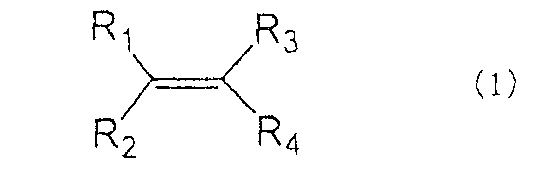
(式(1)において、R1、R2およびR3はそれぞれ独立して水素原子、ハロゲン、炭素数1~4のアルキル基もしくはハロゲン化アルキル基、無置換もしくは置換基のついたフェニル基またはシクロヘキシル基であり、R4は無置換もしくは置換基のついたフェニル基またはシクロヘキシル基である。)
また、本発明は、式(1)で示される化合物が、有機系電解質中に0.05~5重量%配合されていることを特徴とする前記記載の有機系電解質に関する。
また、本発明は、式(1)で示される化合物が1,1-ジフェニルエチレンであることを特徴とする前記のいずれかに記載の有機系電解質に関する。
また、本発明は、式(1)で示される化合物が1,1-ジフェニルエチレンであることを特徴とする前記のいずれかに記載の有機系電解質に関する。
また、本発明は、前記のいずれかに記載の有機系電解質を用いたことを特徴とする有機系電解質蓄電池に関する。
また、本発明は、パウチ型蓄電池であることを特徴とする前記記載の有機系電解質蓄電池に関する。
また、本発明は、パウチ型蓄電池であることを特徴とする前記記載の有機系電解質蓄電池に関する。
式(1)で示される化合物を含有させた本発明の有機系電解質を用いることにより、蓄電池の初期蓄電容量、および高温保存後の蓄電容量を増加させることができる。したがって、本発明の有機系電解質を用いた蓄電池を電気自動車へ搭載、もしくは定置型蓄電池として利用することにより、高温などの環境下での利用による劣化を抑制することができ、蓄電池の利用期間を延ばすことが可能となる。
以下、本発明について詳述する。
本発明は、下記式(1)で示される化合物で示される化合物を含有することを特徴とする有機系電解質である。
本発明は、下記式(1)で示される化合物で示される化合物を含有することを特徴とする有機系電解質である。
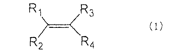
式(1)において、R1、R2およびR3はそれぞれ独立して水素原子、ハロゲン、炭素数1~4のアルキル基もしくはハロゲン化アルキル基、無置換もしくは置換基のついたフェニル基またはシクロヘキシル基であり、R4は無置換もしくは置換基のついたフェニル基またはシクロヘキシル基である。
かかる式(1)で示される化合物としては、具体的には1,1-ジフェニルエチレン、シス-1,2-ジフェニルエチレン、トランス-1,2-ジフェニルエチレン、1-フェニル-1-(3、4-ジメチルフェニル)エチレン、1-フェニル-1-(2、4-ジメチルフェニル)エチレン、1-フェニル-1-(2、5-ジメチルフェニル)エチレン、1-フェニル-1-(2-エチルフェニル)エチレン、1-フェニル-1-(3-エチルフェニル)エチレン、1-フェニル-1-(4-エチルフェニル)エチレン、1-フェニル-1-(2-メチルフェニル)エチレン、1-フェニル-1-(3-メチルフェニル)エチレン、1-フェニル-1-(4-メチルフェニル)エタン、1-(2-メチルフェニル)-1-(4-メチルフェニル)エチレン、1-(2-メチルフェニル)-1-(3-メチルフェニル)エチレン、1-(3-メチルフェニル)-1-(4-メチルフェニル)エチレン、1-フェニル-1-(4-イソブチルフェニル)エチレン、1-フェニル-1-(2-イソブチルフェニル)エチレン、1-フェニル-1-(3-イソブチルフェニル)エチレン、1-フェニル-1-(4-イソプロピルフェニル)エチレン、1-フェニル-1-(2-イソプロピルフェニル)エチレン、1-フェニル-1-(3-イソプロピルフェニル)エチレン、シス-1-(3、4-ジメチルフェニル)-2-フェニルエチレン、トランス-1-(3、4-ジメチルフェニル)-2-フェニルエチレン、シス-1-(2、4-ジメチルフェニル)-2-フェニルエチレン、トランス-1-(2、4-ジメチルフェニル)-2-フェニルエチレン、シス-1-(2、5-ジメチルフェニル)-2-フェニルエチレン、トランス-1-(2、5-ジメチルフェニル)-2-フェニルエチレン、シス-1-(2-エチルフェニル)-2-フェニルエチレン、トランス-1-(2-エチルフェニル)-2-フェニルエチレン、シス-1-(3-エチルフェニル)-2-フェニルエチレン、トランス-1-(3-エチルフェニル)-2-フェニルエチレン、シス-1-(4-エチルフェニル)-2-フェニルエチレン、トランス-1-(4-エチルフェニル)-2-フェニルエチレン、シス-1-(2-メチルフェニル)-2-フェニルエチレン、トランス-1-(2-メチルフェニル)-2-フェニルエチレン、シス-1-(3-メチルフェニル)-2-フェニルエチレン、トランス-1-(3-メチルフェニル)-2-フェニルエチレン、シス-1-(4-メチルフェニル)-2-フェニルエチレン、トランス-1-(4-メチルフェニル)-2-フェニルエチレン、シス-1-(2-メチルフェニル)-2-(4-メチルフェニル)エチレン、トランス-1-(2-メチルフェニル)-2-(4-メチルフェニル)エチレン、シス-1-(2-メチルフェニル)-2-(3-メチルフェニル)エチレン、トランス-1-(2-メチルフェニル)-2-(3-メチルフェニル)エチレン、シス-1-(3-メチルフェニル)-2-(4-メチルフェニル)エチレン、トランス-1-(3-メチルフェニル)-2-(4-メチルフェニル)エチレン、シス-1-(4-イソブチルフェニル)-2-フェニルエチレン、トランス-1-(4-イソブチルフェニル)-2-フェニルエチレン、シス-1-(2-イソブチルフェニル)-2-フェニルエチレン、トランス-1-(2-イソブチルフェニル)-2-フェニルエチレン、シス-1-(3-イソブチルフェニル)-2-フェニルエチレン、トランス-1-(3-イソブチルフェニル)-2-フェニルエチレン、シス-1-(4-イソプロピルフェニル)-2-フェニルエチレン、トランス-1-(4-イソプロピルフェニル
)-2-フェニルエチレン、シス-1-(2-イソプロピルフェニル)-2-フェニルエチレン、トランス-1-(2-イソプロピルフェニル)-2-フェニルエチレン、シス-1-(3-イソプロピルフェニル)-2-フェニルエチレン、トランス-1-(3-イソプロピルフェニル)-2-フェニルエチレン、1,1-ジシクロヘキシルエチレン、シス-1,2-ジシクロヘキシルエチレン、トランス-1,2-ジシクロヘキシルエチレンなどが挙げられる。
)-2-フェニルエチレン、シス-1-(2-イソプロピルフェニル)-2-フェニルエチレン、トランス-1-(2-イソプロピルフェニル)-2-フェニルエチレン、シス-1-(3-イソプロピルフェニル)-2-フェニルエチレン、トランス-1-(3-イソプロピルフェニル)-2-フェニルエチレン、1,1-ジシクロヘキシルエチレン、シス-1,2-ジシクロヘキシルエチレン、トランス-1,2-ジシクロヘキシルエチレンなどが挙げられる。
本発明においては、有機系電解質に前記式(1)で示される化合物を1種以上含有する。
式(1)で示される化合物の含有量は、有機系電解質中に0.05重量%以上、好ましくは0.1重量%以上、より好ましくは0.5重量%以上であり、上限は5重量%以下、好ましくは3重量%以下、より好ましくは2重量%以下である。式(1)で示される化合物の含有量が0.05重量%より少ないと、本発明による効果が得られず、一方5重量%より多いと電極と過剰に反応するなどし、蓄電池の容量が低下する可能性がある。
なお、式(1)で示される化合物が1,1-ジフェニルエチレンの場合、その含有量の上限は1重量%未満であることが好ましい。
なお、式(1)で示される化合物が1,1-ジフェニルエチレンの場合、その含有量の上限は1重量%未満であることが好ましい。
なお、式 (1)で示される化合物の純度は、それぞれ95%以上であることが好ましく、より好ましくは97%以上、さらに好ましくは99%以上である。純度が95%より低い場合には、本発明の効果が得られないおそれがある。
有機系電解質は、主として有機溶媒と電解質塩から構成され、該有機溶媒としては高誘電率溶媒および低粘度溶媒が用いられる。
有機系電解質における高誘電率溶媒の含有割合は5~45容量%であることが好ましく、より好ましくは10~40容量%、さらに好ましくは15~38容量%である。
また有機系電解質における低粘度溶媒の含有割合は55~95容量%であることが好ましく、より好ましくは60~90容量%、さらに好ましくは62~85容量%である。
有機系電解質における高誘電率溶媒の含有割合は5~45容量%であることが好ましく、より好ましくは10~40容量%、さらに好ましくは15~38容量%である。
また有機系電解質における低粘度溶媒の含有割合は55~95容量%であることが好ましく、より好ましくは60~90容量%、さらに好ましくは62~85容量%である。
前記高誘電率溶媒としては、エチレンカーボネート、プロピレンカーボネートの他に、例えば、ブチレンカーボネート、γ―ブチルラクトン、γ―バレロラクトン、テトラヒドロフラン、1,4-ジオキサン、N-メチル-2-ピロリドン、N-メチル-2-オキサゾリジノン、スルホラン、2-メチルスルホランなどが挙げられる。
前記低粘度溶媒としては、ジメチルカーボネート、ジエチルカーボネート、エチルメチルカーボネートの他に例えば、メチルプロピルカーボネート、メチルイソプロピルカーボネート、エチルプロピルカーボネート、ジプロピルカーボネート、メチルブチルカーボネート、ジブチルカーボネート、ジメトキシエタン、酢酸メチル、酢酸エチル、酢酸プロピル、酢酸イソプロピル、酢酸ブチル、酢酸イソブチル、プロピオン酸メチル、プロピオン酸エチル、ギ酸メチル、ギ酸エチル、酪酸メチル、イソ酪酸メチルなどが挙げられる。
電解質塩としては、例えば、六フッ化リン酸リチウム(LiPF6)、四フッ化ホウ酸リチウム(LiBF4)、六フッ化ヒ酸リチウム(LiAsF6)、六フッ化アンチモン酸リチウム(LiSbF6)、過塩素酸リチウム(LiClO4)および四塩化アルミニウム酸リチウム(LiAlCl4)などの無機リチウム塩、並びにトリフルオロメタンスルホン酸リチウム(CF3SO3Li)、リチウムビス(トリフルオロメタンスルホン)イミド[(CF3SO2)2NLi]、リチウムビス(ペンタフルオロエタンスルホン)イミド[(C2F5SO2)2NLi]およびリチウムトリス(トリフルオロメタンスルホン)メチド[(CF3SO2)3CLi]などのパーフルオロアルカンスルホン酸誘導体のリチウム塩が挙げられる。電解質塩は1種を単独で用いてもよく、複数種を混合して用いてもよい。
電解質塩は、通常、0.5~3モル/リットル、好ましくは0.8~2モル/リットル、より好ましくは1.0~1.6モル/リットルの濃度で有機系電解質中に含まれていることが望ましい。
電解質塩は、通常、0.5~3モル/リットル、好ましくは0.8~2モル/リットル、より好ましくは1.0~1.6モル/リットルの濃度で有機系電解質中に含まれていることが望ましい。
また、本発明は、式(1)で示される化合物を含有する有機系電解質を用いた有機系電解質蓄電池を提供する。
本発明の有機系電解質蓄電池において、正極活物質としてはリチウムを吸蔵、放出可能な材料であれば用いることができる。例えば、リチウム含有複合酸化物LiMO2(MはMn、Fe、Co、Niなどの金属より選ばれる1種のみ、または2種以上の混合物であり、一部をMg、Al、Tiなどその他カチオンで置換してもよい)、LiMn2O4、LiMn0.5Ni1.5O4などや、LiFePO4、LiMnPO4などに代表されるオリビン型材料を用いることもできる。その他、Li2MnO3、Li2MSiO4(Mは金属)などのリチウム過剰系材料も用いることができる。
正極としては、リチウムと遷移金属が含まれるものが好ましく、特にコバルトを含む層状酸化物が含まれることが好ましい。
正極としては、リチウムと遷移金属が含まれるものが好ましく、特にコバルトを含む層状酸化物が含まれることが好ましい。
負極には、人造黒鉛または天然黒鉛を含む炭素系負極材料が用いられる。
負極活物質としては、リチウムが挿入可能なもしくはリチウムと反応する負極活物質が用いられる。かかる負極活物質としては、黒鉛を主体とするが、非晶質炭素などの炭素材料、あるいはLi金属、Si、Sn、Al、などのLiと合金を形成する材料、Si酸化物、SiとSi以外の他金属元素を含むSi複合酸化物、Sn酸化物、SnとSn以外の他金属元素を含むSn複合酸化物、Li4Ti5O12などを混合して用いてもよい。
負極活物質としては、リチウムが挿入可能なもしくはリチウムと反応する負極活物質が用いられる。かかる負極活物質としては、黒鉛を主体とするが、非晶質炭素などの炭素材料、あるいはLi金属、Si、Sn、Al、などのLiと合金を形成する材料、Si酸化物、SiとSi以外の他金属元素を含むSi複合酸化物、Sn酸化物、SnとSn以外の他金属元素を含むSn複合酸化物、Li4Ti5O12などを混合して用いてもよい。
セパレータは、電気絶縁性の多孔体から形成されていればよく、例えば、ポリエチレン、ポリプロピレン等のポリオレフィン、ポリエステル、ポリエチレンテレフタレート、ポリイミドなどのポリマー製の膜または繊維不織布が挙げられる。材質は、単独でもよく複数種を用いてもよい。また、セパレータは単層でも良く、多層(複合化膜)であっても良い。また、セラミックなどの無機材料ナノ粒子を含有しても良い。
また、セパレータの両面にポリフッ化ビニリデン等の高分子化合物を塗布して用いても良い。
また、セパレータの両面にポリフッ化ビニリデン等の高分子化合物を塗布して用いても良い。
本発明の有機系電解質蓄電池では、有機溶媒により膨潤して有機系電解質を保持する保持体となる高分子化合物を含むことによりゲル状となった電解質を用いてもよい。有機溶媒により膨潤する高分子化合物を含むことにより高いイオン伝導率を得ることができ、優れた充放電効率が得られると共に、電池の漏液を防止することができるからである。有機系電解質に高分子化合物が含有されている場合、高分子化合物の含有量は、0.1質量%以上10質量%以下の範囲内とすることが好ましい。
また、セパレータの両面にポリフッ化ビニリデン等の高分子化合物を塗布して用いる場合は、有機系電解質と高分子化合物の質量比を50:1~10:1の範囲内とすることが好ましい。この範囲内とすることにより、より高い充放電効率が得られる。
前記高分子化合物としては、例えば、ポリビニルホルマール、ポリエチレンオキサイド並びにポリエチレンオキサイドを含む架橋体などのエーテル系高分子化合物、ポリメタクリレートなどのエステル系高分子化合物、アクリレート系高分子化合物、およびポリフッ化ビニリデン、並びにフッ化ビニリデンとヘキサフルオロプロピレンとの共重合体などのフッ化ビニリデンの重合体が挙げられる。高分子化合物は1種を単独で用いてもよく、複数種を混合して用いてもよい。特に、高温保存時の膨潤防止効果の観点からは、ポリフッ化ビニリデンなどのフッ素系高分子化合物を用いることが望ましい。
以下、実施例、比較例により本発明をさらに具体的に説明するが、本発明はこれらの実施例に限定されるものではない。
なお、ここでは図1を用いてコイン型の有機系電解質蓄電池について説明するが、本発明の有機系電解質蓄電池のタイプはコイン型に限定されるものではなく、例えば、ボタン型、パウチ型、角型、あるいはスパイラル構造を有する筒型などの有機系電解質蓄電池に適用することもできる。また、有機系電解質蓄電池の大きさも任意であり、大型、小型または薄型としてもよい。
なお、ここでは図1を用いてコイン型の有機系電解質蓄電池について説明するが、本発明の有機系電解質蓄電池のタイプはコイン型に限定されるものではなく、例えば、ボタン型、パウチ型、角型、あるいはスパイラル構造を有する筒型などの有機系電解質蓄電池に適用することもできる。また、有機系電解質蓄電池の大きさも任意であり、大型、小型または薄型としてもよい。
(実施例1)
図1は、コイン型の有機系電解質蓄電池の構造を示す模式断面図である。この電池は、正極12と負極14とがセパレータ15を介して積層されたものである。正極12、負極14およびセパレータ15はいずれも円板状であり、金属製の外装部品11および外装部品13によって画成される空間内に収容されている。外装部品11,13の内部は有機系電解質が満たされており、外装部品11,13の周縁部はシールガスケット17を介してかしめられることにより密閉されている。なお、外装部品13と負極14の間には金属製のバネ18とスペーサ19が配置されている。
図1は、コイン型の有機系電解質蓄電池の構造を示す模式断面図である。この電池は、正極12と負極14とがセパレータ15を介して積層されたものである。正極12、負極14およびセパレータ15はいずれも円板状であり、金属製の外装部品11および外装部品13によって画成される空間内に収容されている。外装部品11,13の内部は有機系電解質が満たされており、外装部品11,13の周縁部はシールガスケット17を介してかしめられることにより密閉されている。なお、外装部品13と負極14の間には金属製のバネ18とスペーサ19が配置されている。
正極は以下のように作製した。活物質:コバルト酸リチウム85重量パーセント、導電助剤:アセチレンブラック5重量パーセント、結着材:ポリ(フッ化ビニリデン)(以下、PVDFと略す)10重量パーセントの混合物にN-メチルピロリドン(以下、NMPと略す)を加え、混練し、スラリーを作製した。作製したスラリーをアルミニウム集電体上に滴下し、マイクロメーター付フィルムアプリケーターおよび自動塗工機を用いて製膜し、オーブン中110℃、窒素雰囲気下にて乾燥させた。作製した正極を直径15mmの円形に打ち抜いた後、プレスを行った。正極活物質量は約23mgであった。
負極は以下のように作製した。活物質:人造黒鉛94重量パーセント、導電助剤:アセチレンブラック1重量パーセント、結着材:PVDF5重量パーセントの混合物にNMPを加え、混練し、スラリーを作製した。作製したスラリーを銅集電体上に滴下し、マイクロメーター付フィルムアプリケーターおよび自動塗工機を用いて製膜し、オーブン中110℃、窒素雰囲気下にて乾燥させた。作製した負極を直径15mmの円形に打ち抜いた後、プレスを行った。負極活物質量は約14mgであった。
上述の方法で作製した正極、負極と円形に打ち抜いた、厚さ25マイクロメートルのポリプロピレン製のセパレータ、および種々調製した有機系電解質を用いてコイン型蓄電池を作製した。有機溶媒には、高誘電率溶媒としてエチレンカーボネート(以下、ECと略す)、低粘度溶媒としてジメチルカーボネート(以下、DMCと略す)を使用し、これらをそれぞれ体積比3:7で混合した溶媒にLiPF6を1モル/リットルの割合で溶解させた。また化合物の純度は全て99%以上とした。
以下の表1に示すように化合物を混合して有機系電解質を調製し、前記記載のようにコイン型蓄電池を作製した。

(実施例2)
負極活物質に天然黒鉛を用い、活物質:天然黒鉛91重量パーセント、導電助剤:アセチレンブラック1重量パーセント、結着材:PVDF8重量パーセントとして、その他は実施例1と同様にコイン型蓄電池を作製した。負極活物質量は約12mgであった。
負極活物質に天然黒鉛を用い、活物質:天然黒鉛91重量パーセント、導電助剤:アセチレンブラック1重量パーセント、結着材:PVDF8重量パーセントとして、その他は実施例1と同様にコイン型蓄電池を作製した。負極活物質量は約12mgであった。
以下の表2に示すように化合物を混合し、前記記載のようにコイン型蓄電池を作製した。

(実施例3)
上記記載の方法と同様に塗布、乾燥し、作製した正極および負極(負極活物質は人造黒鉛)をロールプレスによりプレス成形し、正極端子22(図2)、負極端子21(図2)となる電極集電体部(未塗布部)も残し、電極塗布部が約30mm×約40mmになるようにカットすることにより正極シート、負極シートをそれぞれ作製した。正極および負極の活物質量はそれぞれ約160mg、約100mgであった。同正極、負極シート、厚さ25マイクロメートルのポリプロピレン製のセパレータを積層し、これを厚さ約100マイクロメートルのアルミラミネートフィルムで包み、内部に種々調製した有機系電解質を注入、減圧下で熱融着封止することによりパウチ型蓄電池を作製した。本パウチ型蓄電池の概略図を図2に示した。なお、有機溶媒には、高誘電率溶媒としてEC、低粘度溶媒としてDMCを使用し、これらをそれぞれ体積比3:7で混合した溶媒にLiPF6を1モル/リットルの割合で溶解させた。また化合物の純度は全て99%以上とした。
上記記載の方法と同様に塗布、乾燥し、作製した正極および負極(負極活物質は人造黒鉛)をロールプレスによりプレス成形し、正極端子22(図2)、負極端子21(図2)となる電極集電体部(未塗布部)も残し、電極塗布部が約30mm×約40mmになるようにカットすることにより正極シート、負極シートをそれぞれ作製した。正極および負極の活物質量はそれぞれ約160mg、約100mgであった。同正極、負極シート、厚さ25マイクロメートルのポリプロピレン製のセパレータを積層し、これを厚さ約100マイクロメートルのアルミラミネートフィルムで包み、内部に種々調製した有機系電解質を注入、減圧下で熱融着封止することによりパウチ型蓄電池を作製した。本パウチ型蓄電池の概略図を図2に示した。なお、有機溶媒には、高誘電率溶媒としてEC、低粘度溶媒としてDMCを使用し、これらをそれぞれ体積比3:7で混合した溶媒にLiPF6を1モル/リットルの割合で溶解させた。また化合物の純度は全て99%以上とした。
以下の表3に示すように化合物を混合し、前記記載のようにパウチ型蓄電池を作製した。

(比較例1)
以下の表4に示すように1、1-ジフェニルエタンを加えたコイン型蓄電池および化合物を加えないものを実施例1と同様に作製した。

以下の表4に示すように1、1-ジフェニルエタンを加えたコイン型蓄電池および化合物を加えないものを実施例1と同様に作製した。
(比較例2)
以下の表5に示すように1、1-ジフェニルエタンを加えたコイン型蓄電池および化合物を加えないものを実施例2と同様に作製した。

以下の表5に示すように1、1-ジフェニルエタンを加えたコイン型蓄電池および化合物を加えないものを実施例2と同様に作製した。
(比較例3)
以下の表6に示すように1、1-ジフェニルエタンを加えたパウチ型蓄電池および化合物を加えないものを実施例3と同様に作製した。
以下の表6に示すように1、1-ジフェニルエタンを加えたパウチ型蓄電池および化合物を加えないものを実施例3と同様に作製した。

(比較例4)
以下の表7に示すようにビニレンカーボネートを加えたコイン型蓄電池および化合物を加えないものを実施例1と同様に作製した。
以下の表7に示すようにビニレンカーボネートを加えたコイン型蓄電池および化合物を加えないものを実施例1と同様に作製した。

(比較例5)
以下の表8に示すようにビニレンカーボネートを加えたコイン型蓄電池および化合物を加えないものを実施例2と同様に作製した。
以下の表8に示すようにビニレンカーボネートを加えたコイン型蓄電池および化合物を加えないものを実施例2と同様に作製した。

(比較例6)
以下の表9に示すようにビニレンカーボネートを加えたパウチ型蓄電池および化合物を加えないものを実施例3と同様に作製した。
以下の表9に示すようにビニレンカーボネートを加えたパウチ型蓄電池および化合物を加えないものを実施例3と同様に作製した。

上述の方法で作製したコイン型蓄電池およびパウチ型蓄電池を25℃の恒温器内に設置し、充放電試験を行った。まず0.875mAの定電流、4.20Vの定電圧にて8時間充電を行った後、0.875mAの定電流で3.00Vまで放電を行った。この時の放電容量を初期蓄電容量とする。電池1-1、1-2、2-1、2-2、3-1、3-2、および比較例4~6の各電池に関しては高温保存試験を実施した。すなわち、初期充放電後、再び1.75mAの定電流、4.20Vの定電圧にて4時間充電を行った後、電池を60℃の恒温器内に設置した。13日間放置した後、電池を取り出し、25℃の恒温器に設置し、充放電試験を行った。先ず、1.75mAの定電流で3.00Vまで放電を行い、その後1.75mAの定電流、4.20Vの定電圧にて4時間充電を行い、再度1.75mAの定電流で3.00Vまで放電を行った。この時の放電容量、平均電圧をそれぞれ保存後蓄電容量、保存後放電平均電圧とする。パウチ型蓄電池の場合には、0.875mAの代わりに6.00mA、1.75mAの代わりに12.0mAの定電流を用いた。
各電池における初期蓄電容量および比較例(添加なし)の容量を100としたときの各電池の容量比を表10にまとめた(実施例1に対しては比較1-2、実施例2に対しては比較2-2、実施例3に対しては比較3-2の容量をそれぞれ100とした)。

また、電池1-1、1-2、2-1、2-2、3-1、3-2、比較例の保存後蓄電容量、保存後放電平均電圧、および比較例(添加なし)の容量(保存後)を100としたときの各電池の容量比を表11にまとめた(電池1-1および1-2に対しては比較4-2、電池2-1および2-2に対しては比較5-2、電池3-1および電池3-2に対しては比較6-2の保存後蓄電容量をそれぞれ100とした)。

以上の結果より、本発明に係る化合物を有機溶媒に適切な量加えることにより、初期蓄電容量を増加させ、高温保存後の蓄電容量および平均電圧の低下(出力の低下)を抑制する効果があることが明らかである。
本発明の有機系電解質は蓄電池の初期蓄電容量の増加、高温保存後の蓄電容量および平均電圧(出力)を低下を抑制させることができため、本発明の有機系電解質を用いた蓄電池を電気自動車に搭載すれば走行可能距離を伸ばすことが可能であるし、定置型蓄電池に搭載すれば、高温下などの過酷な状況下でも劣化を抑制することが可能である。
Claims (5)
- 下記式(1)で示される化合物を含有することを特徴とする有機系電解質。

- 式(1)で示される化合物が、有機系電解質中に0.05~5重量%配合されていることを特徴とする請求項1に記載の有機系電解質。
- 式(1)で示される化合物が1,1-ジフェニルエチレンであることを特徴とする請求項1~2のいずれかに記載の有機系電解質。
- 請求項1~3のいずれかに記載の有機系電解質を用いたことを特徴とする有機系電解質蓄電池。
- パウチ型蓄電池であることを特徴とする請求項4に記載の有機系電解質蓄電池。
Applications Claiming Priority (2)
| Application Number | Priority Date | Filing Date | Title |
|---|---|---|---|
| JP2012253884A JP2014102961A (ja) | 2012-11-20 | 2012-11-20 | 有機系電解質および有機系電解質蓄電池 |
| JP2012-253884 | 2012-11-20 |
Publications (1)
| Publication Number | Publication Date |
|---|---|
| WO2014080752A1 true WO2014080752A1 (ja) | 2014-05-30 |
Family
ID=50775938
Family Applications (1)
| Application Number | Title | Priority Date | Filing Date |
|---|---|---|---|
| PCT/JP2013/079861 Ceased WO2014080752A1 (ja) | 2012-11-20 | 2013-11-05 | 有機系電解質および有機系電解質蓄電池 |
Country Status (3)
| Country | Link |
|---|---|
| JP (1) | JP2014102961A (ja) |
| TW (1) | TW201440283A (ja) |
| WO (1) | WO2014080752A1 (ja) |
Citations (5)
| Publication number | Priority date | Publication date | Assignee | Title |
|---|---|---|---|---|
| JP2005142157A (ja) * | 2003-10-31 | 2005-06-02 | Samsung Sdi Co Ltd | リチウム二次電池用電解液及びこれを含むリチウム二次電池 |
| JP2009211941A (ja) * | 2008-03-04 | 2009-09-17 | Sony Corp | 非水電解液二次電池 |
| JP2009272170A (ja) * | 2008-05-08 | 2009-11-19 | Sanyo Electric Co Ltd | 非水電解質二次電池 |
| WO2013094603A1 (ja) * | 2011-12-22 | 2013-06-27 | Jx日鉱日石エネルギー株式会社 | 有機系電解質および有機系電解質蓄電池 |
| WO2013094602A1 (ja) * | 2011-12-22 | 2013-06-27 | Jx日鉱日石エネルギー株式会社 | 有機系電解質および有機系電解質蓄電池 |
-
2012
- 2012-11-20 JP JP2012253884A patent/JP2014102961A/ja active Pending
-
2013
- 2013-11-05 WO PCT/JP2013/079861 patent/WO2014080752A1/ja not_active Ceased
- 2013-11-19 TW TW102142101A patent/TW201440283A/zh unknown
Patent Citations (5)
| Publication number | Priority date | Publication date | Assignee | Title |
|---|---|---|---|---|
| JP2005142157A (ja) * | 2003-10-31 | 2005-06-02 | Samsung Sdi Co Ltd | リチウム二次電池用電解液及びこれを含むリチウム二次電池 |
| JP2009211941A (ja) * | 2008-03-04 | 2009-09-17 | Sony Corp | 非水電解液二次電池 |
| JP2009272170A (ja) * | 2008-05-08 | 2009-11-19 | Sanyo Electric Co Ltd | 非水電解質二次電池 |
| WO2013094603A1 (ja) * | 2011-12-22 | 2013-06-27 | Jx日鉱日石エネルギー株式会社 | 有機系電解質および有機系電解質蓄電池 |
| WO2013094602A1 (ja) * | 2011-12-22 | 2013-06-27 | Jx日鉱日石エネルギー株式会社 | 有機系電解質および有機系電解質蓄電池 |
Also Published As
| Publication number | Publication date |
|---|---|
| JP2014102961A (ja) | 2014-06-05 |
| TW201440283A (zh) | 2014-10-16 |
Similar Documents
| Publication | Publication Date | Title |
|---|---|---|
| CN103797634B (zh) | 非水电解液电池用电解液及非水电解液电池 | |
| JP5573313B2 (ja) | 非水電解液電池用電解液及びこれを用いる非水電解液電池 | |
| CN104396080B (zh) | 具有提高的寿命特性的锂二次电池 | |
| JP2019057356A (ja) | 非水電解液電池用電解液、及びこれを用いた非水電解液電池 | |
| JP6109746B2 (ja) | 有機系電解質および有機系電解質蓄電池 | |
| EP2840640A1 (en) | Electrolyte for lithium secondary battery and lithium secondary battery containing same | |
| TWI487164B (zh) | 用於二次電池之電解質及包含其之鋰二次電池 | |
| KR101865440B1 (ko) | 비수 전해액 및 이를 갖는 리튬 이차전지 | |
| CN102136601A (zh) | 锂离子电池 | |
| US20230411693A1 (en) | Non-aqueous electrolyte and secondary battery, battery module, battery pack and electrical device containing the same | |
| KR20230056000A (ko) | 전해액, 이차전지와 전기장치 | |
| JP6031450B2 (ja) | 有機系電解質および有機系電解質蓄電池 | |
| WO2013094603A1 (ja) | 有機系電解質および有機系電解質蓄電池 | |
| CN103326065B (zh) | 钛酸锂电池及其电解液 | |
| KR101744245B1 (ko) | 고전압 리튬 이차전지 | |
| WO2014080752A1 (ja) | 有機系電解質および有機系電解質蓄電池 | |
| WO2016027588A1 (ja) | 有機系電解質および有機系電解質蓄電池 | |
| KR20080035824A (ko) | 고온 저장 성능을 향상시키는 전해액 및 이를 포함하는이차 전지 | |
| EP2838149A1 (en) | Organic electrolyte and organic electrolyte storage cell using same |
Legal Events
| Date | Code | Title | Description |
|---|---|---|---|
| 121 | Ep: the epo has been informed by wipo that ep was designated in this application |
Ref document number: 13857346 Country of ref document: EP Kind code of ref document: A1 |
|
| NENP | Non-entry into the national phase |
Ref country code: DE |
|
| 122 | Ep: pct application non-entry in european phase |
Ref document number: 13857346 Country of ref document: EP Kind code of ref document: A1 |