WO2014077102A1 - ガラス板積層体及びその製造方法 - Google Patents
ガラス板積層体及びその製造方法 Download PDFInfo
- Publication number
- WO2014077102A1 WO2014077102A1 PCT/JP2013/078862 JP2013078862W WO2014077102A1 WO 2014077102 A1 WO2014077102 A1 WO 2014077102A1 JP 2013078862 W JP2013078862 W JP 2013078862W WO 2014077102 A1 WO2014077102 A1 WO 2014077102A1
- Authority
- WO
- WIPO (PCT)
- Prior art keywords
- glass plate
- laser
- glass
- fusing
- glass plates
- Prior art date
Links
- 239000011521 glass Substances 0.000 title claims abstract description 244
- 238000004519 manufacturing process Methods 0.000 title claims abstract description 26
- 230000002093 peripheral effect Effects 0.000 claims abstract description 27
- 238000007789 sealing Methods 0.000 claims abstract description 24
- 230000003746 surface roughness Effects 0.000 claims abstract description 11
- 238000010030 laminating Methods 0.000 claims abstract description 8
- 238000005520 cutting process Methods 0.000 claims description 32
- 239000012298 atmosphere Substances 0.000 claims description 4
- 230000001678 irradiating effect Effects 0.000 claims description 3
- 238000003698 laser cutting Methods 0.000 abstract description 11
- 239000007789 gas Substances 0.000 description 81
- 238000010583 slow cooling Methods 0.000 description 50
- 238000007493 shaping process Methods 0.000 description 40
- 238000002347 injection Methods 0.000 description 33
- 239000007924 injection Substances 0.000 description 33
- 239000006060 molten glass Substances 0.000 description 17
- 238000000034 method Methods 0.000 description 13
- 238000002844 melting Methods 0.000 description 10
- 230000008018 melting Effects 0.000 description 10
- 230000004048 modification Effects 0.000 description 7
- 238000012986 modification Methods 0.000 description 7
- 230000008569 process Effects 0.000 description 7
- 238000003466 welding Methods 0.000 description 6
- 230000009471 action Effects 0.000 description 5
- 239000000853 adhesive Substances 0.000 description 5
- 230000001070 adhesive effect Effects 0.000 description 5
- 230000015572 biosynthetic process Effects 0.000 description 5
- 239000003795 chemical substances by application Substances 0.000 description 5
- 239000005340 laminated glass Substances 0.000 description 5
- 238000007665 sagging Methods 0.000 description 5
- 230000000694 effects Effects 0.000 description 4
- 238000010438 heat treatment Methods 0.000 description 4
- 230000003287 optical effect Effects 0.000 description 4
- 238000013459 approach Methods 0.000 description 3
- 238000006297 dehydration reaction Methods 0.000 description 3
- 239000001257 hydrogen Substances 0.000 description 3
- 229910052739 hydrogen Inorganic materials 0.000 description 3
- 239000000155 melt Substances 0.000 description 3
- 125000006850 spacer group Chemical group 0.000 description 3
- 238000005411 Van der Waals force Methods 0.000 description 2
- 230000006835 compression Effects 0.000 description 2
- 238000007906 compression Methods 0.000 description 2
- 238000001816 cooling Methods 0.000 description 2
- 238000010586 diagram Methods 0.000 description 2
- 238000005304 joining Methods 0.000 description 2
- 125000005372 silanol group Chemical group 0.000 description 2
- 239000000126 substance Substances 0.000 description 2
- 241000283014 Dama Species 0.000 description 1
- OAICVXFJPJFONN-UHFFFAOYSA-N Phosphorus Chemical compound [P] OAICVXFJPJFONN-UHFFFAOYSA-N 0.000 description 1
- 238000006124 Pilkington process Methods 0.000 description 1
- 230000001154 acute effect Effects 0.000 description 1
- 239000000654 additive Substances 0.000 description 1
- 230000000996 additive effect Effects 0.000 description 1
- QVGXLLKOCUKJST-UHFFFAOYSA-N atomic oxygen Chemical compound [O] QVGXLLKOCUKJST-UHFFFAOYSA-N 0.000 description 1
- 230000004888 barrier function Effects 0.000 description 1
- 238000007664 blowing Methods 0.000 description 1
- 239000006059 cover glass Substances 0.000 description 1
- 230000006837 decompression Effects 0.000 description 1
- JNSGIVNNHKGGRU-JYRVWZFOSA-N diethoxyphosphinothioyl (2z)-2-(2-amino-1,3-thiazol-4-yl)-2-methoxyiminoacetate Chemical compound CCOP(=S)(OCC)OC(=O)C(=N/OC)\C1=CSC(N)=N1 JNSGIVNNHKGGRU-JYRVWZFOSA-N 0.000 description 1
- 238000009826 distribution Methods 0.000 description 1
- 230000004927 fusion Effects 0.000 description 1
- 230000006872 improvement Effects 0.000 description 1
- 239000004973 liquid crystal related substance Substances 0.000 description 1
- 229910001416 lithium ion Inorganic materials 0.000 description 1
- 239000000463 material Substances 0.000 description 1
- 238000007500 overflow downdraw method Methods 0.000 description 1
- 239000001301 oxygen Substances 0.000 description 1
- 229910052760 oxygen Inorganic materials 0.000 description 1
- 238000003825 pressing Methods 0.000 description 1
- 230000009467 reduction Effects 0.000 description 1
- 239000011347 resin Substances 0.000 description 1
- 229920005989 resin Polymers 0.000 description 1
- 238000000926 separation method Methods 0.000 description 1
- 230000035939 shock Effects 0.000 description 1
- 238000001179 sorption measurement Methods 0.000 description 1
- 239000007921 spray Substances 0.000 description 1
- 238000004544 sputter deposition Methods 0.000 description 1
- 239000000758 substrate Substances 0.000 description 1
- 238000001771 vacuum deposition Methods 0.000 description 1
- 238000007740 vapor deposition Methods 0.000 description 1
- 238000004804 winding Methods 0.000 description 1
Images


Classifications
-
- C—CHEMISTRY; METALLURGY
- C03—GLASS; MINERAL OR SLAG WOOL
- C03B—MANUFACTURE, SHAPING, OR SUPPLEMENTARY PROCESSES
- C03B33/00—Severing cooled glass
- C03B33/08—Severing cooled glass by fusing, i.e. by melting through the glass
- C03B33/082—Severing cooled glass by fusing, i.e. by melting through the glass using a focussed radiation beam, e.g. laser
-
- C—CHEMISTRY; METALLURGY
- C03—GLASS; MINERAL OR SLAG WOOL
- C03B—MANUFACTURE, SHAPING, OR SUPPLEMENTARY PROCESSES
- C03B23/00—Re-forming shaped glass
- C03B23/20—Uniting glass pieces by fusing without substantial reshaping
- C03B23/24—Making hollow glass sheets or bricks
- C03B23/245—Hollow glass sheets
-
- C—CHEMISTRY; METALLURGY
- C03—GLASS; MINERAL OR SLAG WOOL
- C03B—MANUFACTURE, SHAPING, OR SUPPLEMENTARY PROCESSES
- C03B25/00—Annealing glass products
- C03B25/02—Annealing glass products in a discontinuous way
- C03B25/025—Glass sheets
-
- C—CHEMISTRY; METALLURGY
- C03—GLASS; MINERAL OR SLAG WOOL
- C03B—MANUFACTURE, SHAPING, OR SUPPLEMENTARY PROCESSES
- C03B33/00—Severing cooled glass
- C03B33/07—Cutting armoured, multi-layered, coated or laminated, glass products
-
- H—ELECTRICITY
- H10—SEMICONDUCTOR DEVICES; ELECTRIC SOLID-STATE DEVICES NOT OTHERWISE PROVIDED FOR
- H10K—ORGANIC ELECTRIC SOLID-STATE DEVICES
- H10K50/00—Organic light-emitting devices
- H10K50/80—Constructional details
- H10K50/84—Passivation; Containers; Encapsulations
- H10K50/844—Encapsulations
-
- H—ELECTRICITY
- H10—SEMICONDUCTOR DEVICES; ELECTRIC SOLID-STATE DEVICES NOT OTHERWISE PROVIDED FOR
- H10K—ORGANIC ELECTRIC SOLID-STATE DEVICES
- H10K50/00—Organic light-emitting devices
- H10K50/80—Constructional details
- H10K50/84—Passivation; Containers; Encapsulations
- H10K50/841—Self-supporting sealing arrangements
-
- H—ELECTRICITY
- H10—SEMICONDUCTOR DEVICES; ELECTRIC SOLID-STATE DEVICES NOT OTHERWISE PROVIDED FOR
- H10K—ORGANIC ELECTRIC SOLID-STATE DEVICES
- H10K71/00—Manufacture or treatment specially adapted for the organic devices covered by this subclass
- H10K71/40—Thermal treatment, e.g. annealing in the presence of a solvent vapour
- H10K71/421—Thermal treatment, e.g. annealing in the presence of a solvent vapour using coherent electromagnetic radiation, e.g. laser annealing
Definitions
- the present invention relates to a technique for improving a glass plate laminate formed by laminating and integrating a plurality of glass plates, and particularly to a glass plate laminate used as a glass package containing elements therein.
- glass packages in which elements such as organic light emitting diodes (OLEDs) are housed between glass plates have been widely used.
- OLEDs organic light emitting diodes
- the glass plate laminate constituting the glass package has high gas barrier properties derived from the glass plate. That is, since an element such as an OLED is easily deteriorated when exposed to oxygen or moisture in the surrounding environment, the element is sealed with a glass plate.
- this type of glass package is usually manufactured by housing an element between two glass plates and sealing the periphery of the element with a frit.
- Patent Document 1 discloses that a frit is heated and melted by a laser in a state where an element is accommodated between two glass plates to form a sealed structure.
- an object of the present invention is to provide a glass plate laminate that can reliably ensure the airtightness of the internal space while reducing the manufacturing cost.
- the present invention devised to solve the above problems is a method for producing a glass plate laminate formed by laminating and integrating a plurality of glass plates, the surface of the plurality of glass plates including a planned cutting line.
- a surface contact portion is formed by surface-contacting each other to form a surface contact portion, and the surface roughness Ra of the surface contact portion is set to 2.0 nm or less, along the planned cutting line included in the surface contact portion. It is characterized by laser cutting and processing the sealing end surface of the surface contact portion into a curved surface and sealing with heat at the time of laser cutting.
- the plurality of glass plates are laminated in a state in which the surfaces including the planned cutting lines are in surface contact with each other.
- the surface roughness Ra of the surface contact portions of the plurality of glass plates is set to 2.0 nm or less, the surface contact portions can be peeled but are brought into close contact without requiring an adhesive or the like.
- This adhesion force is considered to be caused by van der Waals force between opposing glass surface molecules or hydrogen bonds between silanol groups formed by moisture adsorption in the air. Then, when the surface contact portion thus tightly fixed is laser-cut, the surface contact portion is completely sealed by the heat at the time of laser cutting.
- the region affected by the heat at the time of laser fusing in addition to the portion to be joined at a temperature equal to or higher than the softening point (hereinafter sometimes referred to as “welded portion”), the softening point.
- a part to be joined at the following temperature hereinafter, sometimes referred to as “quasi-welded part”. Therefore, sealing of the surface contact portion is promoted.
- the reason why the quasi-welded portion occurs is considered to be that a dehydration reaction occurs between silanol groups forming hydrogen bonds on the opposing glass surfaces, resulting in stronger covalent bonds.
- the glass plate is cut while melting, so that the cut end surface of the glass plate can be processed into a curved surface. Therefore, the end face strength can be sufficiently ensured even if the chamfering process is not separately performed afterwards.
- a functional member may be accommodated between the plurality of glass plates, and the surface contact portion may be formed around the functional member, and then the laser fusing may be performed.
- the functional member refers to a material or an element that can exhibit a predetermined function, such as a phosphor, a liquid crystal, an organic EL, an ITO film, a solar battery, a Li ion battery, and an antireflection film.
- the periphery of the functional member can be temporarily sealed by the surface contact portion without applying heat before laser cutting.
- the surface contact portion is laser-cut, as described above, the glass of the surface contact portion is melted and the periphery of the functional member can be completely sealed.
- the heating range of the glass plate is limited to a narrow range where the laser is irradiated, so that the functional member can be prevented from being deteriorated by heat. .
- the surface contact portion is pressure-bonded before the laser fusing.
- the surface contact portion may be formed under a reduced pressure atmosphere.
- the plurality of glass plates may be composed of three or more glass plates.
- the total thickness of the plurality of glass plates is preferably 0.5 mm or less.
- the present invention devised to solve the above problems is a glass plate laminate formed by laminating and integrating a plurality of glass plates, and the outer peripheral portion of the glass plate laminate is a fire-making surface comprising a curved surface. And a sealing portion is formed in the vicinity of the outer peripheral portion in which the plurality of glass plates are hermetically sealed, and the sealing surfaces are made in order from the outer peripheral portion side so that the glass surfaces cannot be separated from each other. It is characterized by including the 1st junction part integrated directly, and the 2nd junction part to which the glass surfaces whose surface roughness Ra is 2.0 nm or less were closely_contact
- “directly” means that no other member such as an adhesive is interposed between the glass surfaces.
- the glass plate laminate produced by the production method already described has such a specific configuration.
- the first joint portion includes a weld portion joined at a temperature equal to or higher than the softening point and a semi-weld portion joined at a temperature equal to or lower than the softening point.
- the outer peripheral portion is formed with a fire-making surface formed of a single arc.
- a functional member may be accommodated between the plurality of glass plates, and the periphery thereof may be surrounded by the sealing portion.
- the present invention it is possible to simultaneously perform the sealing operation of the gaps between the glass plates in the laminated state and the chamfering processing of the end surfaces of the glass plates. Therefore, the airtightness of the internal space can be reliably ensured while the manufacturing cost is reduced.
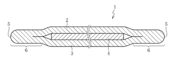
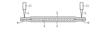
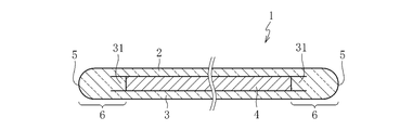
- the glass plate laminated body 1 which concerns on 1st Embodiment of this invention laminated
- the functional member 4 is accommodated in an airtight state therein.
- the outer peripheral part 5 of the glass plate laminated body 1 is formed with the fire-making surface which consists of a curved surface.
- the outer peripheral part 5 is comprised by the curved surface which consists of a substantially single circular arc which continues smoothly.
- a sealed portion 6 is formed in which a plurality of glass plates 2 and 3 are sealed with each other.
- the sealing portion 6 is formed on the entire circumference of the glass plate laminate 1.
- the shape of the glass plate laminate 1 in plan view is generally a quadrangle with four corners chamfered, but may be, for example, a triangle, other polygons, or a circle. The reason why the degree of freedom of the shape is high is that the outer peripheral portion 5 of the glass plate laminate 1 is formed by laser fusing, as will be described later.
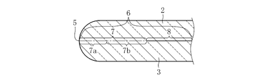
- the sealing portion 6 includes, in order from the outer peripheral portion 5 side, a first joint portion 7 in which glass surfaces are directly integrated so as not to be peeled, and a glass surface having a surface roughness Ra of 2.0 nm or less. It is comprised from the 2nd junction part 8 which mutually contact
- the first joint portion 7 includes, sequentially from the outer peripheral portion 5 side, a weld portion 7a joined at a temperature equal to or higher than a softening point (for example, 700 to 1000 ° C.) and a semi-weld portion 7b joined at a temperature equal to or lower than the softening point. . That is, the 1st junction part 7 (welding part 7a and semi-welding part 7b) is joined firmly by receiving a thermal influence. In this embodiment, the interface between the glass plates 2 and 3 cannot be confirmed at the welded portion 7a and the semi-welded portion 7b. Of course, the semi-welded portion 7 b may have an interface between the glass plates 2 and 3.
- a softening point for example, 700 to 1000 ° C.
- the second bonding portion 8 is bonded only by the adhesive force derived from the surface properties of the smooth glass surface without using an adhesive or the like. This adhesion force is considered to be caused by van der Waals force or hydrogen bond. That is, the second joint portion 8 is not affected by heat and maintains a joined state. In this embodiment, the interface between the glass plates 2 and 3 can be confirmed at the second joint 8.
- the surface roughness Ra of the glass surface in the second bonding portion 8 is preferably 1.0 nm or less, and more preferably 0.5 nm or less (particularly 0.2 nm or less).
- the sealing portion is generally formed in an area of about 3 to 5 mm from the periphery of the outer peripheral portion.
- the sealing portion 6 of this embodiment has a width from the outer peripheral portion 5, for example. It is also possible to form it in an area of about 0.05 to 1 mm.
- the size of the region of the sealing portion 6 can be appropriately changed by adjusting the irradiation heat of a fusing laser or a slow cooling laser described later.
- the plate thickness of the glass plates 2 and 3 is, for example, 0.2 mm or less.
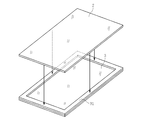
- moderate flexibility can be imparted to the glass plates 2 and 3, so that the glass plates 2 and 3 are accommodated in a state in which the functional member 4 is accommodated therein as shown in FIG.
- These end portions can be deformed so as to be pulled toward the center in the thickness direction and sealed.
- the deformation amount of the glass plates 2 and 3 is exaggerated.
- the functional member 4 examples include a light emitting layer used for organic EL lighting, an organic EL display, and the like.
- the functional member 4 may be omitted as appropriate, or a resin film or the like may be interposed instead of the functional member 4. In the latter case, for example, it can be used as a cover glass of an electronic device such as a mobile phone.
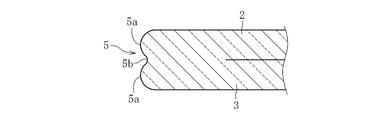
- the shape of the outer peripheral portion 5 of the glass plate laminate 1 may be, for example, a curved surface shape as shown in FIGS.
- a plurality (two in the illustrated example) of peak portions 5a may be smoothly continuous via the valley portions 5b.
- part may be sufficient.
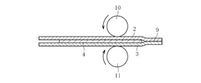
- two glass plates 2 and 3 having a surface roughness Ra of 2.0 nm or less are prepared.
- the glass plates 2 and 3 can be formed by, for example, an overflow down draw method.
- the functional member 4 is formed or arrange
- the glass surfaces of the two glass plates 2 and 3 that have protruded to the outside of the functional member 4 are brought into close contact with each other to form a surface contact portion 9 around the functional member 4.
- the surface roughness Ra of the glass plates 2 and 3 may be 2.0 nm or less over the entire front and back surfaces, but only the glass surface constituting the surface contact portion 9 may be 2.0 nm or less. .
- the glass plates 2 and 3 are pressed while being sandwiched between the pair of rollers 10 to press the surface contact portion 9.
- the decompression process is a part of the process such as vapor deposition inside the vacuum chamber used for the process when the functional film such as AR film is formed on the surface of the glass plates 2 and 3 by low temperature vacuum deposition or low temperature sputtering.
- a laser for example, CO2 laser
- CO2 laser CO2 laser
- This laser fusing is performed over the entire circumference of the glass plates 2 and 3.
- the sealing part 6 is formed in the manufactured glass plate laminated body 1 along the outer peripheral part.
- the sealing portion 6 is formed by laser fusing the surface contact portion 9 in a special close contact state, and thus shows a characteristic sealed state derived from the surface contact portion 9. That is, in this case, the glass surfaces can be bonded together at a temperature equal to or lower than the softening point, so that the first bonded portion 7 is bonded at a temperature equal to or higher than the softening point. And a semi-welded portion 7b joined at a temperature of.
- the outer peripheral portion (fused end surface) 5 of the glass plate laminate 1 becomes a fire-making surface formed of a curved surface. Therefore, end face strength can be sufficiently ensured without performing chamfering separately.
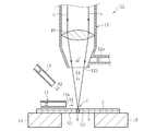
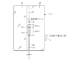
- the laser fusing device 11 includes a laser beam L toward the surface of the processing table 15 on which the two glass plates 2 and 3 are stacked and the upper glass plate 2.
- the assist gas injection nozzle 13 for injecting the assist gas A 2 for scattering the molten glass M melted by the heating of the laser L, and the glass plate 2.
- a shaping gas injection nozzle 14 for injecting the shaping gas A3 along the surface.
- the glass plate 2 may be referred to as “upper glass plate” and the glass plate 3 may be referred to as “lower glass plate”, but the orientation of the surfaces of the glass plates 2 and 3 is limited to the vertical direction. Is not to be done.
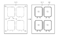
- the glass plates 2 and 3 are divided into the product part G1 and the non-product part G2, the product part G1 becomes the above-mentioned glass plate laminated body 1.
- the laser irradiator 12 is installed at a fixed position, and includes a cylindrical base end portion and a mortar-shaped tip end portion.
- a lens 16 that collects a laser beam L emitted from a laser oscillator (not shown) and irradiates it toward the surface of the upper glass plate 2 is attached to the inner peripheral wall of the base end portion.
- a gas introduction pipe 12a for introducing the gas A1 injected along the irradiation direction of the laser L into the laser irradiator 12 is connected to the tip portion, and the laser L and the gas A1 are irradiated and injected.
- An irradiating port 12b for this purpose is formed.
- the assist gas injection nozzle 13 is installed at a fixed position in the same manner as the laser irradiator 12 and is installed in an inclined posture with respect to the surface of the upper glass plate 2.
- the shape is formed in a cylindrical shape, and the assist gas A2 compressed by a gas compression device (for example, an air compressor) (not shown) passes through the inside and is injected toward the irradiation part C of the laser L. It is comprised so that.
- the shaping gas injection nozzle 14 is installed at a fixed position in the same manner as the laser irradiator 12 and the assist gas injection nozzle 13 and is in a posture parallel to the surface of the upper glass plate 2 and in the surface direction of the glass plate 2. It is installed in a direction orthogonal to the extended planned cutting line CL.
- tip is formed in the substantially rectangular shape, and the injection port 14a is wide in the direction along the cutting projected line CL.
- the shaping gas A3 compressed by the gas compression apparatus not shown is configured to pass through the inside thereof and be injected in parallel with the surface of the upper glass plate 2 from the injection port 14a.
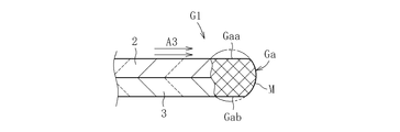
- this shaping gas A3 is injected toward the side used as the non-product part G2 from the side used as the product part G1 among the cut glass plates 2 and 3.
- FIG. Note that the planned cutting line CL is preferably formed of a closed circuit (for example, a circle or a rectangle) in which the start end and the end end are continuous when the glass plate is viewed in plan.
- a pair of processing tables 15 are installed in parallel across the planned cutting line CL. Moreover, both the process bases 15 become a structure which can move synchronizing with the T direction (direction parallel to the cutting projected line CL) shown in FIG. 7 in the state in which the glass plates 2 and 3 were mounted. ing.
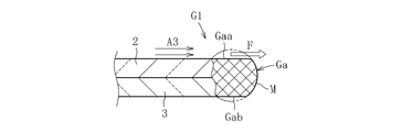
- the laser irradiator 12 moves along the planned cutting line CL along with the movement of the processing table 15 on which the glass plates 2 and 3 are placed in the T direction. Are continuously irradiated with laser L. Then, the molten glass M melted by the irradiation part C of the laser L is removed by blowing off and scattering the assist gas A2 ejected from the assist gas spray nozzle 13. After that, the shaping gas A3 injected from the shaping gas injection nozzle 14 passes along the surface of the upper glass plate 2 through the fusing end Ga formed sequentially on the glass plates 2 and 3 with the removal of the molten glass M. And it is comprised so that it may pass orthogonally to the advancing direction of cutting. Further, the dross scattered when the molten glass M is removed is prevented from adhering to the lens 16 by the pressure of the gas A1 ejected from the laser irradiator 12.
- the injection pressures of the gas A1, the assist gas A2, and the shaping gas A3 are the gas A1: 0.0 to 0.02 MPa, the assist gas A2: 0.00 to 0.25 MPa, and the shaping gas A3: 0.01, respectively. It is preferably ⁇ 1.00 MPa. Further, the separation distance between the injection port 14a formed in the shaping gas injection nozzle 14 and the planned cutting line CL is preferably 1 to 30 mm, and more preferably 1 to 10 mm. Furthermore, the angle formed by the injection direction of the assist gas A2 and the surface of the upper glass plate 2 is preferably 25 to 60 °.
- the molten glass M tends to be rounded by the action of the surface tension, and the surface Gaa and the back surface Gab of the fused end portion Ga protrude (this state is also referred to as “dama”). .)
- a force F that pushes the protrusion in the surface direction of the glass plate 2 acts on the protrusion to be formed on the surface Gaa by the pressure of the shaping gas A3.
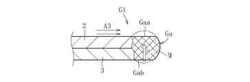
- the surface Gaa side of the fusing end Ga is placed under a state where the atmospheric pressure is lower than that of the back Gab side because the shaping gas A3 passes through the surface Gaa side. Therefore, as shown in FIG. 8C, a force P acts to push the protrusion to be formed on the back surface Gab from the back surface Gab side having a high atmospheric pressure to the front surface Gaa side having a low atmospheric pressure.
- a force P acts to push the protrusion to be formed on the back surface Gab from the back surface Gab side having a high atmospheric pressure to the front surface Gaa side having a low atmospheric pressure.
- the shaping gas A3 is injected in parallel with the surface of the upper glass plate 2, so that the flow velocity of the injected shaping gas A3 is changed to the shaping gas A3 and the upper glass plate.
- the occurrence of a situation where the vehicle is decelerated due to a collision with 2 can be prevented as much as possible.
- the higher the flow velocity of the shaping gas A3 passing through the fusing end Ga the higher the pressure of the shaping gas A3 that acts on the ledge that is to be formed on the surface Gaa side, and the pressure difference between the surface Gaa side and the back surface Gab side. Becomes larger.
- the injection port 14a formed in the shaping gas injection nozzle 14 is wide in the direction along the surface of the upper glass plate 2, the injected shaping gas A3 follows the shape of the injection port 14a. Thus, it spreads over a wide range of the melted end Ga. For this reason, it becomes possible to prevent the formation of the bulge at the melted end portion Ga more stably.
- the assist gas A2 is sprayed toward the irradiation part C of the laser L, the molten glass M melted in the irradiation part C can be scattered and removed by the pressure of the assist gas A2, Removal of the molten glass M can be performed more quickly and smoothly.
- the shape of the melted end portion Ga is poorly formed due to an excessive amount of the molten glass M such as formation of lumps.
- the injected shaping gas A3 passes through the fusing end Ga along the surface of the upper glass plate 2, the fusing end Ga is moved from the front surface Gaa side to the back surface Gab side by the shaping gas A3. It is also possible to prevent strong pressing. For this reason, no sagging is formed in the cut end portion Ga by the shaping gas A3.
- sagging refers to a state in which the melted end portion Ga is formed in a state of hanging downward as compared with other portions.
- dross generated when the glass plates 2 and 3 are cut easily scatters toward the injection destination side of the shaping gas A3. Therefore, it becomes difficult for dross to adhere to the melted end portion Ga of the product portion G1 located on the injection source side of the shaping gas A3 in the glass plates 2 and 3 after cutting, and the product portion G1 is made of high quality. be able to.
- the cutting progress direction and the direction in which the shaping gas passes through the laser irradiation section are orthogonal to each other, but these may be intersected without being orthogonal to each other. It may be good or parallel. That is, the shaping gas may be injected in any direction as long as the injected shaping gas passes through the laser irradiation section along the surface of the glass plate. Further, the shaping gas is not necessarily injected in parallel with the surface of the glass plate, and may be injected from a direction inclined with respect to the surface of the upper glass plate 2 as shown in FIG. In this case, the angle ⁇ formed by the injection direction of the shaping gas and the surface of the upper glass plate 2 is preferably 0 to 25 °.
- the shaping gas is injected so as to pass only on the surface side of the fusing end along the surface of the glass plate.
- the shaping gas A3 may be injected not only on the front surface Gaa side but also on the back surface Gab side. In this case, it is preferable that the shaping gas A3 injected to the back surface Gab side is injected so that the flow velocity passing through the fusing end Ga is slower than the shaping gas A3 injected to the front surface Gaa side.
- the pressure on the back surface Gab side is maintained higher than that on the front surface Gaa side, there is a risk that the action of pushing the protrusion to be formed on the back surface Gab from the back surface Gab side to the front surface Gaa side may be lost. Can be eliminated.
- the shaping gas A3 may be injected so as to pass through the back surface Gab, the shaping gas A3 may be injected from a direction inclined with respect to the back surface of the lower glass plate 3.
- the shaping gas A3 may be injected only on the back surface Gab side of the melted end portion Ga of the lower glass plate 3, and even in this case, there is a certain effect of preventing the occurrence of lumps and sagging.
- the laser fusing device described above has a configuration in which molten glass is scattered and removed by jetting the assist gas, but it is possible to remove the molten glass without jetting the assist gas. In this case, moisture and volatile components in the glass, or energy when the glass itself vaporizes and expands, becomes a driving force for removing the molten glass, whereby the molten glass is scattered and removed.
- the shape of the injection port formed in the shaping gas injection nozzle is rectangular in the above example, but is not limited thereto, and may be formed in any shape.
- the shaping gas injected from the injection port has a shape that spreads over a wide range of the melted end, and such a shape has, for example, a long diameter in a direction parallel to the surface of the glass plate. An ellipse or the like is assumed.
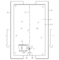
- the laser fusing device 21 includes a fusing laser irradiator 22, a slow cooling laser irradiator 23, and an assist gas injection nozzle 24. .
- the shaping gas injection nozzle 14 described in the first embodiment is omitted.
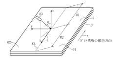
- the fusing laser irradiator 22 irradiates the fusing laser LB1 substantially vertically onto the planned cutting line CL formed on the two laminated glass plates 2 and 3.
- a first irradiation region SP1 is formed in a part of the planned cutting line CL of the glass plates 2 and 3.
- the first irradiation is performed by moving the glass plates 2 and 3 in the transport direction (in the direction of arrow A in the figure) by a processing table (not shown) (for example, a transport belt that sucks and holds the glass plates 2 and 3).
- the region SP1 is scanned along the planned cutting line CL, and the laminated glass plates 2 and 3 are continuously laser fused.
- a fusing gap S is formed between the fusing end face Ga1 on the side to be the product part G1 and the fusing end face Gb1 on the side to be the non-product part G2.
- the slow cooling laser irradiator 23 irradiates the slow cooling laser LB2 obliquely from the upper side of the non-product part G2 toward the planned cutting line CL.
- a second irradiation region SP2 serving as a slow cooling execution part is formed in a part of the planned cutting line CL of the glass plates 2 and 3.
- the second irradiation region SP2 is a long and narrow region (for example, an ellipse) along the planned cutting line CL, and the dimension of the second irradiation region SP2 is the fusing progress direction along the planned cutting line CL.
- the dimension is larger than the dimension of the first irradiation region SP1 of the fusing laser LB1.
- region SP2 has overlapped with 1st irradiation area
- the glass plates 2 and 3 are heated in the second irradiation region SP2, the glass plates 2 and 3 are blown at a fusing temperature (for example, 1300 to 3000 ° C.) in a region continuous before and after the fusing progress direction of the first irradiation region SP1. It is heated at a lower temperature (for example, 100 to 1000 ° C.). That is, in the second irradiation region SP2, the glass plates 2 and 3 are preheated in the region SP2a on the front side in the fusing progress direction of the first irradiation region SP1, and the region on the rear side in the fusing direction of the first irradiation region SP1. The glass plates 2 and 3 are gradually cooled at SP2b. Then, by moving the glass plates 2 and 3 as described above, the second irradiation region SP2 is scanned along the planned cutting line CL, and the glass plates 2 and 3 are preheated and gradually cooled before and after fusing. Is applied continuously.
- the assist gas injection nozzle 24 injects the assist gas AG from above to the first irradiation region SP1 in order to blow away the molten glass M generated in the first irradiation region SP1.
- the assist gas injection nozzle 24 is disposed above the product part G1 side, and the assist gas AG is injected obliquely downward with respect to the first irradiation region SP1.
- the position of the assist gas injection nozzle 24 is not particularly limited.
- the assist gas injection nozzle 24 is disposed immediately above the planned cutting line CL, and the assist gas is disposed substantially perpendicular to the glass plates 2 and 3 together with the fusing laser. You may make it inject AG.
- the assist gas injection nozzle 24 may be disposed in the lower space of the glass plates 2 and 3 so as to blow the molten glass from below. These assist gases AG are for efficient fusing, but may be omitted.
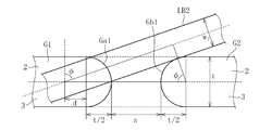
- the laser irradiator 23 for slow cooling is disposed at an upper position on the side that becomes the non-product part G2 of the unfinished part R2.
- the slow cooling laser LB2 emitted from the slow cooling laser irradiator 23 is inclined so as to approach the glass plates 2 and 3 as it moves from the uncut portion R2 side to the blow completed portion R1 side. Yes.
- the slow cooling laser LB2 may be inclined so as to approach the glass plates 2 and 3 as it moves from the fusing completion portion R1 side to the fusing incomplete portion R2 side. That is, the slow cooling laser LB2 has an azimuth angle ⁇ and a polar angle ⁇ as shown in the figure. Therefore, as shown in FIG.
- the second irradiation region SP2 projected on the glass plates 2 and 3 has an oval shape.
- the direction of the major axis of the oval shape changes depending on the magnitude of the azimuth angle ⁇ , but has a component in the fusing progress direction.
- the cross-sectional shape orthogonal to the optical axis of the slow cooling laser LB2 may be shaped in advance into an oval shape so that the direction of the major axis of the oval is along the fusing direction.
- an optical component such as a cylindrical lens, a slit light shielding mask, or the like can be used.
- the azimuth angle ⁇ and polar angle ⁇ of the slow cooling laser LB2 are preferably in the following ranges. That is, the azimuth angle ⁇ is preferably in the range of 0 ⁇ ⁇ ⁇ ⁇ .
- the effect of irradiation is the same in any range of 0 ⁇ ⁇ ⁇ ⁇ / 2 and ⁇ / 2 ⁇ ⁇ ⁇ ⁇ with respect to the azimuth angle ⁇ .
- the glass plates 2 and 3 are defocused irradiated at a position below the condensing point, 0 ⁇ ⁇ ⁇ ⁇ / 2 is an appropriate range, and conversely, the glass plates 2 and 3 are located above the condensing point.
- ⁇ / 2 ⁇ ⁇ ⁇ ⁇ is an appropriate range.
- the polar angle ⁇ preferably satisfies the following range when a parallel beam is used as the slow cooling laser LB2.
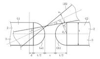
- the polar angle ⁇ is 0 ⁇ ⁇ cos -1 [where the beam diameter of the slow cooling laser LB2 is w2, the total thickness of the laminated glass plates 2 and 3 is t, and the adjustment amount of the irradiation position is d. It is preferable to satisfy the range of (t + w2) / ⁇ 2 (s + t + d) ⁇ ]. Further, as shown in FIG. 14B, the polar angle ⁇ preferably satisfies the following range when a focused beam is adopted as the slow cooling laser LB2 and is irradiated with defocusing. .
- the polar angle ⁇ is the beam diameter w2 at the contact point when the slow cooling laser LB2 is in contact with the non-product part G2, the condensing angle ⁇ , the thickness t of the glass plates 2 and 3, and the irradiation position.
- the adjustment amount is d, it is preferable to satisfy the range of 0 ⁇ ⁇ cos ⁇ 1 [(tcos ⁇ + w 2) / ⁇ 2 (s + t + d) ⁇ ].
- the polar angle ⁇ is preferably set to an angle range that does not interfere with the vicinity of the melted end face Ga1 of the non-product part G2 that is close to and faces the melted end face Ga1 of the product part G1.
- the irradiation position of the slow cooling laser LB2 is preferably adjusted according to the position of the tensile stress generated in the vicinity of the fusing end face Ga1 of the product part G1 before the slow cooling, and the adjustment amount d is, for example, ⁇ 0.5 t ⁇ d ⁇ 2.5t is adjusted.
- the slow cooling laser LB2 is shaped so that the cross section orthogonal to the optical axis is elliptical, the second irradiation region SP2 having a long overall length can be obtained without increasing the inclination angle (polar angle ⁇ ). Can be formed.
- the glass plates 2 and 3 are irradiated with the laser LB1 for fusing from the fusing laser irradiator 22 while the glass plates 2 and 3 are conveyed. Thereby, the glass plates 2 and 3 are fused.
- the assist gas AG is injected from the assist gas injection nozzle 24 into the first irradiation region SP1 of the fusing laser LB1, and the molten glass M is blown off from the first irradiation region SP1.
- the glass plates 2 and 3 are irradiated with the laser LB2 for slow cooling from the laser irradiator 23 for slow cooling.
- the second irradiation region SP2 of the slow cooling laser LB2 overlaps the first irradiation region SP1 so as to straddle the fusing progress direction of the first irradiation region SP1 of the fusing laser LB1. Due to this overlap, preheating is performed in the region SP2a on the front side in the fusing progress direction of the first irradiation region SP1 in the second irradiation region SP2, and slow cooling is performed in the region SP2b on the rear side in the fusing progress direction. Is done.
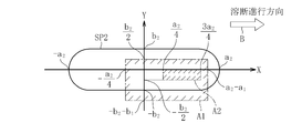
- the line extending through the center position in the direction orthogonal to the fusing progress direction of the second irradiation region SP2 and extending in the fusing direction is the X axis, and the fusing of the X axis and the second irradiation region SP2 is performed.
- Y-axis a line perpendicular at the center position in the traveling direction, 2a 2 a X-axis dimension of the second irradiation region SP2, 2b 2 a Y-axis dimension of the second irradiation region SP2, X-axis direction of the first irradiation region SP1
- the dimension is 2a 1
- the Y-axis direction dimension of the first irradiation area SP1 is 2b 1
- the center coordinates of the first irradiation area SP1 are (x, y), the first irradiation area SP1 and the second irradiation area SP2
- the preferred relationship between is:
- the relationship between the spot diameters of the first irradiation region SP1 and the second irradiation region SP2 is a 1 ⁇ a 2 and b 1 ⁇ b 2 . 50a 1 ⁇ a 2 30b 1 ⁇ b 2 (1) It is preferable that The center coordinates (x, y) of the first irradiation region SP1 are -A 2/4 ⁇ x ⁇ a 2 -a 1 -B 2 -b 1 ⁇ y ⁇ b 2/2 ⁇ (2) It is preferable to satisfy the relationship (region indicated by A1 in FIG. 15B), a 2/4 ⁇ x ⁇ 3a 2/4 -B 2/2 ⁇ y ⁇ 0 ⁇ (3) It is more preferable to satisfy the relationship (region indicated by A2 in FIG. 15B).
- the size relationship and the positional relationship between the first irradiation region SP1 and the second irradiation region SP2 become optimal, and the product portion G1 of the glass plates 2 and 3 Generation of thermal residual strain can be reliably reduced.
- the second irradiation region SP2 is formed so as to be biased toward the product part G1 side rather than the non-product part G2 side, and the center position of the second irradiation region SP2 in the fusing progress direction ( The first irradiation region SP1 overlaps the second irradiation region SP2 on the front side of the Y-axis position).
- the thermal residual distortion of the product part G1 is reduced. It becomes possible to reduce more reliably.
- the dimension in the fusing progress direction of the region SP2b where the slow cooling is performed becomes longer than the dimension in the fusing progress direction of the region SP2a where the preheating is performed. Since thermal residual strain is caused by rapid cooling after fusing, it is preferable to lengthen the region for slow cooling and reduce the cooling rate as described above in order to remove the thermal residual strain. It becomes.
- the melting of the glass plates 2 and 3 is completed by melting from the upper surface side of the upper glass plate 2 by the fusing laser LB1, and the cutting groove formed by the melting penetrates downward.
- the fusing end surface Ga1 of the product part G1 is more strongly affected by the irradiation heat supplied at the time of fusing as it approaches the upper surface, and the thermal residual strain of the fusing end surface Ga1 is relatively large on the upper surface side. It is considered a thing. Therefore, in order to remove the residual strain of the blown end face Ga1 of the product part G1, it is preferable to supply a larger amount of heat to the upper surface side of the cut end face Ga1 and perform a slow cooling process. Therefore, as shown in FIGS.
- the slow cooling laser LB2 directly irradiates the upper part (for example, the upper half region) of the melted end face Ga1 of the product part G1.
- the laser LB2 for slow cooling is irradiated obliquely from above to the melted end surface Ga1 to be gradually cooled through the melted gap S between the melted end surfaces Ga1 and Gb1 formed by melting.
- the wavelengths of the two lasers are made different by using lasers oscillated by different oscillators as the fusing laser and the slow cooling laser. In this way, a continuous interference fringe is not formed temporally by the fusing laser and the slow cooling laser, and it becomes easy to sufficiently control the energy distribution given to the glass plate.
- region SP2 may be isolate
- the surface contact portion 9 is more than in the case where the fusing laser LB1 is irradiated alone.
- the dehydration reaction occurs in a wide range. Therefore, the formation range of the 2nd welding part 7b can be expanded, and higher airtightness can be ensured.
- the formation range of the 2nd welding part 7b can be suitably changed by adjustment of laser LB2 for slow cooling.
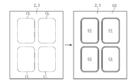
- the start point S and the end point E of the planned cutting line CL may be formed outside the region defining the product part G1. Further, the start point S and the end point E do not have to coincide with each other.
- each contact part of the surface of the glass plates 2 and 3 and the surface of the glass plate 31 used as a spacer comprises a surface contact part.
- the glass plate laminated body 1 which has the sealing part 6 containing the outer peripheral part 5 which consists of a fusion
- the laser fusing method and the like are the same as those in the first and second embodiments, and a detailed description thereof will be omitted.
- the glass plate laminate according to the present invention can be manufactured under the laser fusing and slow cooling conditions shown in Table 1 below.
- the number of laminated glass plates is two, and in Example 2, the number of laminated glass plates is three.
- board thickness of a glass plate shall be 0.1 mm in any Example.
Landscapes
- Chemical & Material Sciences (AREA)
- Engineering & Computer Science (AREA)
- Materials Engineering (AREA)
- Organic Chemistry (AREA)
- Physics & Mathematics (AREA)
- Optics & Photonics (AREA)
- Health & Medical Sciences (AREA)
- Toxicology (AREA)
- Laser Beam Processing (AREA)
- Re-Forming, After-Treatment, Cutting And Transporting Of Glass Products (AREA)
- Ceramic Engineering (AREA)
- Life Sciences & Earth Sciences (AREA)
- Chemical Kinetics & Catalysis (AREA)
- General Chemical & Material Sciences (AREA)
- Geochemistry & Mineralogy (AREA)
- Joining Of Glass To Other Materials (AREA)
- Electroluminescent Light Sources (AREA)
Priority Applications (4)
| Application Number | Priority Date | Filing Date | Title |
|---|---|---|---|
| EP13854877.1A EP2921462B1 (en) | 2012-11-13 | 2013-10-24 | Glass sheet laminate and method for producing same |
| CN201380056195.5A CN104854045B (zh) | 2012-11-13 | 2013-10-24 | 玻璃板层叠体及其制造方法 |
| KR1020157000944A KR102071366B1 (ko) | 2012-11-13 | 2013-10-24 | 유리판 적층체 및 그 제조 방법 |
| US14/442,498 US9701565B2 (en) | 2012-11-13 | 2013-10-24 | Glass sheet laminate and method for producing same |
Applications Claiming Priority (2)
| Application Number | Priority Date | Filing Date | Title |
|---|---|---|---|
| JP2012-249305 | 2012-11-13 | ||
| JP2012249305A JP5958823B2 (ja) | 2012-11-13 | 2012-11-13 | ガラス板積層体及びその製造方法 |
Publications (1)
| Publication Number | Publication Date |
|---|---|
| WO2014077102A1 true WO2014077102A1 (ja) | 2014-05-22 |
Family
ID=50731020
Family Applications (1)
| Application Number | Title | Priority Date | Filing Date |
|---|---|---|---|
| PCT/JP2013/078862 WO2014077102A1 (ja) | 2012-11-13 | 2013-10-24 | ガラス板積層体及びその製造方法 |
Country Status (7)
Cited By (1)
| Publication number | Priority date | Publication date | Assignee | Title |
|---|---|---|---|---|
| JP2017186204A (ja) * | 2016-04-07 | 2017-10-12 | 英興株式会社 | シリカガラス溶接方法 |
Families Citing this family (10)
| Publication number | Priority date | Publication date | Assignee | Title |
|---|---|---|---|---|
| JP6243641B2 (ja) * | 2013-07-02 | 2017-12-06 | 三菱電線工業株式会社 | ガラス構造体の製造方法 |
| JP6631935B2 (ja) * | 2015-01-05 | 2020-01-15 | 日本電気硝子株式会社 | ガラス板の製造方法 |
| US11243192B2 (en) | 2016-09-27 | 2022-02-08 | Vaon, Llc | 3-D glass printable hand-held gas chromatograph for biomedical and environmental applications |
| US10821707B2 (en) * | 2018-05-17 | 2020-11-03 | Vaon, Llc | Multi-layer, flat glass structures |
| US11203183B2 (en) | 2016-09-27 | 2021-12-21 | Vaon, Llc | Single and multi-layer, flat glass-sensor structures |
| JP6963754B2 (ja) * | 2016-10-05 | 2021-11-10 | 日本電気硝子株式会社 | ガラス樹脂積層体の製造方法及びガラス樹脂積層体 |
| CN110177766B (zh) * | 2017-02-07 | 2021-12-10 | 日本电气硝子株式会社 | 玻璃膜的制造方法 |
| JP6931919B2 (ja) * | 2017-08-31 | 2021-09-08 | 三星ダイヤモンド工業株式会社 | ガラス基板の残留応力低減方法及びガラス基板の残留応力低減装置 |
| JP6931918B2 (ja) * | 2017-08-31 | 2021-09-08 | 三星ダイヤモンド工業株式会社 | ガラス基板の端面処理方法及びガラス基板の端面処理装置 |
| CN110627380A (zh) * | 2019-09-16 | 2019-12-31 | 深圳市裕展精密科技有限公司 | 玻璃复合件、玻璃复合件的制备方法以及激光焊接设备 |
Citations (5)
| Publication number | Priority date | Publication date | Assignee | Title |
|---|---|---|---|---|
| JPH0768395A (ja) * | 1993-09-01 | 1995-03-14 | Hitachi Cable Ltd | ガラスの切断方法およびその装置 |
| JP2005281126A (ja) * | 2004-03-02 | 2005-10-13 | Nippon Electric Glass Co Ltd | タブレット一体型ガラス管及びその製造方法 |
| JP2006524419A (ja) | 2003-04-16 | 2006-10-26 | コーニング インコーポレイテッド | フリットにより密封されたガラスパッケージおよびその製造方法 |
| WO2010097908A1 (ja) * | 2009-02-25 | 2010-09-02 | セイコーインスツル株式会社 | 接合ガラスの切断方法、パッケージの製造方法、パッケージ、圧電振動子、発振器、電子機器及び電波時計 |
| JP2011037685A (ja) * | 2009-08-17 | 2011-02-24 | Nippon Electric Glass Co Ltd | 素子封止体及びその製造方法並びに素子の封止方法 |
Family Cites Families (11)
| Publication number | Priority date | Publication date | Assignee | Title |
|---|---|---|---|---|
| DE4444547C2 (de) * | 1994-12-14 | 1997-02-27 | Schott Rohrglas Gmbh | Verfahren zum wärmeweichen Trennen von dünnwandigen Glasrohren oder -platten |
| JP2000281368A (ja) * | 1999-03-31 | 2000-10-10 | Shin Meiwa Ind Co Ltd | ガラス板の製造方法 |
| WO2001057638A1 (en) * | 2000-01-31 | 2001-08-09 | Touch Panel Systems K.K. | Touch panel and method for using the same |
| CN1693244A (zh) * | 2005-04-29 | 2005-11-09 | 陶礼德 | 玻璃真空板及其制造方法 |
| JP5522881B2 (ja) | 2006-09-06 | 2014-06-18 | イムラ アメリカ インコーポレイテッド | 材料を接合するための方法 |
| DE102007008540A1 (de) * | 2007-02-21 | 2008-08-28 | Friedrich-Schiller-Universität Jena | Verfahren zum Laser-gestützten Bonden, derart gebondete Substrate und deren Verwendung |
| JP5733600B2 (ja) * | 2009-07-03 | 2015-06-10 | 日本電気硝子株式会社 | 素子封止体の製造方法、及び素子封止体 |
| TWI572480B (zh) * | 2011-07-25 | 2017-03-01 | 康寧公司 | 經層壓及離子交換之強化玻璃疊層 |
| US9010151B2 (en) * | 2011-09-15 | 2015-04-21 | Nippon Electric Glass Co., Ltd. | Glass sheet cutting method |
| US9162919B2 (en) * | 2012-02-28 | 2015-10-20 | Corning Incorporated | High strain point aluminosilicate glasses |
| US9914657B2 (en) * | 2013-04-30 | 2018-03-13 | Corning Incorporated | Apparatus and method for thermal profile control in an isopipe |
-
2012
- 2012-11-13 JP JP2012249305A patent/JP5958823B2/ja active Active
-
2013
- 2013-10-24 CN CN201380056195.5A patent/CN104854045B/zh active Active
- 2013-10-24 US US14/442,498 patent/US9701565B2/en active Active
- 2013-10-24 KR KR1020157000944A patent/KR102071366B1/ko active Active
- 2013-10-24 EP EP13854877.1A patent/EP2921462B1/en active Active
- 2013-10-24 WO PCT/JP2013/078862 patent/WO2014077102A1/ja active Application Filing
- 2013-11-06 TW TW102140197A patent/TWI579139B/zh active
Patent Citations (5)
| Publication number | Priority date | Publication date | Assignee | Title |
|---|---|---|---|---|
| JPH0768395A (ja) * | 1993-09-01 | 1995-03-14 | Hitachi Cable Ltd | ガラスの切断方法およびその装置 |
| JP2006524419A (ja) | 2003-04-16 | 2006-10-26 | コーニング インコーポレイテッド | フリットにより密封されたガラスパッケージおよびその製造方法 |
| JP2005281126A (ja) * | 2004-03-02 | 2005-10-13 | Nippon Electric Glass Co Ltd | タブレット一体型ガラス管及びその製造方法 |
| WO2010097908A1 (ja) * | 2009-02-25 | 2010-09-02 | セイコーインスツル株式会社 | 接合ガラスの切断方法、パッケージの製造方法、パッケージ、圧電振動子、発振器、電子機器及び電波時計 |
| JP2011037685A (ja) * | 2009-08-17 | 2011-02-24 | Nippon Electric Glass Co Ltd | 素子封止体及びその製造方法並びに素子の封止方法 |
Non-Patent Citations (1)
| Title |
|---|
| See also references of EP2921462A4 |
Cited By (1)
| Publication number | Priority date | Publication date | Assignee | Title |
|---|---|---|---|---|
| JP2017186204A (ja) * | 2016-04-07 | 2017-10-12 | 英興株式会社 | シリカガラス溶接方法 |
Also Published As
| Publication number | Publication date |
|---|---|
| KR20150084755A (ko) | 2015-07-22 |
| JP2014097905A (ja) | 2014-05-29 |
| EP2921462A1 (en) | 2015-09-23 |
| CN104854045A (zh) | 2015-08-19 |
| EP2921462A4 (en) | 2016-09-14 |
| TWI579139B (zh) | 2017-04-21 |
| KR102071366B1 (ko) | 2020-01-30 |
| JP5958823B2 (ja) | 2016-08-02 |
| US9701565B2 (en) | 2017-07-11 |
| US20160272532A1 (en) | 2016-09-22 |
| EP2921462B1 (en) | 2018-03-28 |
| CN104854045B (zh) | 2017-12-19 |
| TW201425014A (zh) | 2014-07-01 |
Similar Documents
| Publication | Publication Date | Title |
|---|---|---|
| JP5958823B2 (ja) | ガラス板積層体及びその製造方法 | |
| CN103619765B (zh) | 玻璃板切断方法及玻璃板切断装置 | |
| JP5861864B2 (ja) | ガラス板切断方法およびガラス板切断装置 | |
| JP4935325B2 (ja) | 脆性材料の割断方法およびその装置 | |
| WO2014030521A1 (ja) | 複合シートの切断方法、ガラスシートの切断方法、複合シートの切断片 | |
| JP2012209133A (ja) | 気密容器、画像表示装置及びこれらの製造方法 | |
| KR101073459B1 (ko) | 접합 기판의 단자 가공 방법 | |
| WO2015031435A2 (en) | Method of separating a glass sheet from a carrier | |
| JP2011144093A (ja) | 板状ガラスの製造方法及びその装置 | |
| KR20130045166A (ko) | 유리 기판의 스크라이브 방법 및 가공 장치 | |
| WO2013122099A1 (ja) | レーザ切断方法およびレーザ切断装置 | |
| JP2009187823A (ja) | 気密容器の製造方法 | |
| CN104364208B (zh) | 玻璃基板的切割方法及玻璃基板的制造方法 | |
| US9725353B2 (en) | Laser fusion-cutting method for plate glass | |
| KR100910047B1 (ko) | 유연성 레이저 조사영역을 이용한 평판 디스플레이 패널의실링방법 | |
| US20160176748A1 (en) | A sealing method for the glass plate | |
| JP2013063864A (ja) | ガラス板切断方法およびガラス板切断装置 | |
| TWI651279B (zh) | 利用雷射光之玻璃基板熔接方法及雷射加工裝置 | |
| JP2005338281A (ja) | 薄膜デバイスの製造方法およびガラス基板の貼り合わせ方法 | |
| JP2013075769A (ja) | ガラス板切断方法およびガラス板切断装置 | |
| JP5884691B2 (ja) | ガラス板切断方法 | |
| JP2014048432A (ja) | セル基板の加工方法 | |
| JP2006150642A (ja) | セル及びセルの製造方法 | |
| JP2013216541A (ja) | ガラス溶着方法 | |
| JP6327580B2 (ja) | ガラスフィルム積層体および電子デバイスの製造方法 |
Legal Events
| Date | Code | Title | Description |
|---|---|---|---|
| 121 | Ep: the epo has been informed by wipo that ep was designated in this application |
Ref document number: 13854877 Country of ref document: EP Kind code of ref document: A1 |
|
| ENP | Entry into the national phase |
Ref document number: 20157000944 Country of ref document: KR Kind code of ref document: A |
|
| NENP | Non-entry into the national phase |
Ref country code: DE |
|
| WWE | Wipo information: entry into national phase |
Ref document number: 14442498 Country of ref document: US |
|
| WWE | Wipo information: entry into national phase |
Ref document number: 2013854877 Country of ref document: EP |