WO2014073304A1 - 成形物製造装置、および成形物製造方法 - Google Patents
成形物製造装置、および成形物製造方法 Download PDFInfo
- Publication number
- WO2014073304A1 WO2014073304A1 PCT/JP2013/077166 JP2013077166W WO2014073304A1 WO 2014073304 A1 WO2014073304 A1 WO 2014073304A1 JP 2013077166 W JP2013077166 W JP 2013077166W WO 2014073304 A1 WO2014073304 A1 WO 2014073304A1
- Authority
- WO
- WIPO (PCT)
- Prior art keywords
- pressure
- mold
- temperature
- resin
- control unit
- Prior art date
- Legal status (The legal status is an assumption and is not a legal conclusion. Google has not performed a legal analysis and makes no representation as to the accuracy of the status listed.)
- Ceased
Links
Images




Classifications
-
- B—PERFORMING OPERATIONS; TRANSPORTING
- B29—WORKING OF PLASTICS; WORKING OF SUBSTANCES IN A PLASTIC STATE IN GENERAL
- B29C—SHAPING OR JOINING OF PLASTICS; SHAPING OF MATERIAL IN A PLASTIC STATE, NOT OTHERWISE PROVIDED FOR; AFTER-TREATMENT OF THE SHAPED PRODUCTS, e.g. REPAIRING
- B29C43/00—Compression moulding, i.e. applying external pressure to flow the moulding material; Apparatus therefor
- B29C43/32—Component parts, details or accessories; Auxiliary operations
- B29C43/58—Measuring, controlling or regulating
-
- B—PERFORMING OPERATIONS; TRANSPORTING
- B29—WORKING OF PLASTICS; WORKING OF SUBSTANCES IN A PLASTIC STATE IN GENERAL
- B29C—SHAPING OR JOINING OF PLASTICS; SHAPING OF MATERIAL IN A PLASTIC STATE, NOT OTHERWISE PROVIDED FOR; AFTER-TREATMENT OF THE SHAPED PRODUCTS, e.g. REPAIRING
- B29C35/00—Heating, cooling or curing, e.g. crosslinking or vulcanising; Apparatus therefor
- B29C35/02—Heating or curing, e.g. crosslinking or vulcanizing during moulding, e.g. in a mould
-
- B—PERFORMING OPERATIONS; TRANSPORTING
- B29—WORKING OF PLASTICS; WORKING OF SUBSTANCES IN A PLASTIC STATE IN GENERAL
- B29C—SHAPING OR JOINING OF PLASTICS; SHAPING OF MATERIAL IN A PLASTIC STATE, NOT OTHERWISE PROVIDED FOR; AFTER-TREATMENT OF THE SHAPED PRODUCTS, e.g. REPAIRING
- B29C35/00—Heating, cooling or curing, e.g. crosslinking or vulcanising; Apparatus therefor
- B29C35/02—Heating or curing, e.g. crosslinking or vulcanizing during moulding, e.g. in a mould
- B29C35/0288—Controlling heating or curing of polymers during moulding, e.g. by measuring temperatures or properties of the polymer and regulating the process
-
- B—PERFORMING OPERATIONS; TRANSPORTING
- B29—WORKING OF PLASTICS; WORKING OF SUBSTANCES IN A PLASTIC STATE IN GENERAL
- B29C—SHAPING OR JOINING OF PLASTICS; SHAPING OF MATERIAL IN A PLASTIC STATE, NOT OTHERWISE PROVIDED FOR; AFTER-TREATMENT OF THE SHAPED PRODUCTS, e.g. REPAIRING
- B29C37/00—Component parts, details, accessories or auxiliary operations, not covered by group B29C33/00 or B29C35/00
- B29C37/0003—Discharging moulded articles from the mould
-
- B—PERFORMING OPERATIONS; TRANSPORTING
- B29—WORKING OF PLASTICS; WORKING OF SUBSTANCES IN A PLASTIC STATE IN GENERAL
- B29C—SHAPING OR JOINING OF PLASTICS; SHAPING OF MATERIAL IN A PLASTIC STATE, NOT OTHERWISE PROVIDED FOR; AFTER-TREATMENT OF THE SHAPED PRODUCTS, e.g. REPAIRING
- B29C43/00—Compression moulding, i.e. applying external pressure to flow the moulding material; Apparatus therefor
- B29C43/003—Compression moulding, i.e. applying external pressure to flow the moulding material; Apparatus therefor characterised by the choice of material
-
- B—PERFORMING OPERATIONS; TRANSPORTING
- B29—WORKING OF PLASTICS; WORKING OF SUBSTANCES IN A PLASTIC STATE IN GENERAL
- B29C—SHAPING OR JOINING OF PLASTICS; SHAPING OF MATERIAL IN A PLASTIC STATE, NOT OTHERWISE PROVIDED FOR; AFTER-TREATMENT OF THE SHAPED PRODUCTS, e.g. REPAIRING
- B29C43/00—Compression moulding, i.e. applying external pressure to flow the moulding material; Apparatus therefor
- B29C43/02—Compression moulding, i.e. applying external pressure to flow the moulding material; Apparatus therefor of articles of definite length, i.e. discrete articles
- B29C43/021—Compression moulding, i.e. applying external pressure to flow the moulding material; Apparatus therefor of articles of definite length, i.e. discrete articles characterised by the shape of the surface
-
- B—PERFORMING OPERATIONS; TRANSPORTING
- B29—WORKING OF PLASTICS; WORKING OF SUBSTANCES IN A PLASTIC STATE IN GENERAL
- B29C—SHAPING OR JOINING OF PLASTICS; SHAPING OF MATERIAL IN A PLASTIC STATE, NOT OTHERWISE PROVIDED FOR; AFTER-TREATMENT OF THE SHAPED PRODUCTS, e.g. REPAIRING
- B29C43/00—Compression moulding, i.e. applying external pressure to flow the moulding material; Apparatus therefor
- B29C43/02—Compression moulding, i.e. applying external pressure to flow the moulding material; Apparatus therefor of articles of definite length, i.e. discrete articles
- B29C43/021—Compression moulding, i.e. applying external pressure to flow the moulding material; Apparatus therefor of articles of definite length, i.e. discrete articles characterised by the shape of the surface
- B29C2043/023—Compression moulding, i.e. applying external pressure to flow the moulding material; Apparatus therefor of articles of definite length, i.e. discrete articles characterised by the shape of the surface having a plurality of grooves
- B29C2043/025—Compression moulding, i.e. applying external pressure to flow the moulding material; Apparatus therefor of articles of definite length, i.e. discrete articles characterised by the shape of the surface having a plurality of grooves forming a microstructure, i.e. fine patterning
-
- B—PERFORMING OPERATIONS; TRANSPORTING
- B29—WORKING OF PLASTICS; WORKING OF SUBSTANCES IN A PLASTIC STATE IN GENERAL
- B29C—SHAPING OR JOINING OF PLASTICS; SHAPING OF MATERIAL IN A PLASTIC STATE, NOT OTHERWISE PROVIDED FOR; AFTER-TREATMENT OF THE SHAPED PRODUCTS, e.g. REPAIRING
- B29C43/00—Compression moulding, i.e. applying external pressure to flow the moulding material; Apparatus therefor
- B29C43/32—Component parts, details or accessories; Auxiliary operations
- B29C43/58—Measuring, controlling or regulating
- B29C2043/5808—Measuring, controlling or regulating pressure or compressing force
-
- B—PERFORMING OPERATIONS; TRANSPORTING
- B29—WORKING OF PLASTICS; WORKING OF SUBSTANCES IN A PLASTIC STATE IN GENERAL
- B29C—SHAPING OR JOINING OF PLASTICS; SHAPING OF MATERIAL IN A PLASTIC STATE, NOT OTHERWISE PROVIDED FOR; AFTER-TREATMENT OF THE SHAPED PRODUCTS, e.g. REPAIRING
- B29C43/00—Compression moulding, i.e. applying external pressure to flow the moulding material; Apparatus therefor
- B29C43/32—Component parts, details or accessories; Auxiliary operations
- B29C43/58—Measuring, controlling or regulating
- B29C2043/5816—Measuring, controlling or regulating temperature
-
- B—PERFORMING OPERATIONS; TRANSPORTING
- B29—WORKING OF PLASTICS; WORKING OF SUBSTANCES IN A PLASTIC STATE IN GENERAL
- B29L—INDEXING SCHEME ASSOCIATED WITH SUBCLASS B29C, RELATING TO PARTICULAR ARTICLES
- B29L2011/00—Optical elements, e.g. lenses, prisms
- B29L2011/0016—Lenses
Definitions
- the present invention relates to a molded product manufacturing apparatus and a manufacturing method for manufacturing a molded product using a mold, and more particularly to a manufacturing apparatus and a manufacturing method of a wafer level lens array using a resin.
- the manufacture of a molded product using a mold is widely used when mass-producing molded products having a predetermined shape using resin, glass, metal, or the like as a main material.
- resin optical lenses used in various electronic devices such as optical pickups for optical disk (CD, DVD, etc.) drives and small cameras mounted on portable terminal devices also use molds. It is manufactured. Many of these lenses are manufactured by applying or pouring a resin (optical polymer) into a mold and performing a curing reaction in the mold.
- the mobile terminal device by using a lens that is mass-produced using a mold, the mobile terminal device can be reduced in weight and size, and the manufacturing cost can be reduced.
- a method for manufacturing a small number of lenses there is known a method for manufacturing a wafer level lens array by applying or pouring a resin as a lens material into a mold having a plurality of lens molds arranged.
- the wafer level lens array is a molded product having a configuration in which a substrate portion and a lens are integrally formed. Generally, a plurality of formed lenses are connected to each other through the substrate portion.
- the wafer level lens array is peeled from the mold (release), and the substrate portion between the lenses is cut to separate the individual lenses, so that the lenses can be mass-produced.
- the wafer level lens array (molded product) may adhere strongly to the mold and cannot be released smoothly.
- the external force applied when releasing the formed lens may cause damage to the lens, scratches on the surface, or distortion of the lens spherical surface (causing lens aberration), which may impair the optical characteristics of the lens. There is sex. For this reason, it is important to release the wafer level lens array smoothly in order to ensure the quality and productivity of the lens.
- Patent Document 1 A method of manufacturing a wafer level lens array including a step of releasing a molded product by applying ultrasonic vibration to a mold is described.
- Patent Document 2 in a molding method in which a resin material is sandwiched between two molds and a resin molded product is molded, one mold is cooled by a predetermined temperature, and the resin molded product is separated from the cooled mold.
- a molding method including a mold release step of a resin molded product is disclosed.
- Patent Document 3 a flat plate-shaped vibrator is brought into direct contact with a molded resin molded product, and vibrations of sound waves or ultrasonic waves are transmitted to the resin molded product, and this vibration is also indirectly applied to the casting mold.
- a mold release method for facilitating mold release of a resin molded product by telling it is disclosed.
- Patent Document 4 discloses a method for manufacturing a glass optical lens and a press molding die for an optical lens used for manufacturing an annular type diffractive lens having a plurality of concentric annular zones.
- the optical lens press mold has a diffraction transfer surface and a step transfer surface. And the surface roughness of the step transfer surface is formed to be rougher than the surface roughness of the diffractive transfer surface, reducing the stress generated in the lens material at the time of mold release, and the glass becomes a press molding die for optical lenses. Suppresses adhesion.
- vibration is transmitted by directly contacting the vibrator with the molded product, and therefore there is a possibility that the contacted vibrator or the transmitted vibration may damage the lens. is there.
- the mold release method described in Patent Document 4 is limited in the shape of the mold, and is difficult to apply to applications other than the production of an annular type diffractive lens having a plurality of concentric annular zones. is there.
- the present invention has been made in view of the above-described problems, and its object is to adhere strongly to a mold in a method for manufacturing a wafer level lens array having excellent optical characteristics such as high light transmittance and high refraction.
- An object is to realize a molded product manufacturing method and a manufacturing apparatus capable of releasing a lens smoothly and without degrading the quality and productivity of the lens.
- a molded product manufacturing apparatus includes a molding die for molding a thermosetting resin, a pressure control unit that controls pressure applied to the molding die, and the molding die.
- the temperature control unit advances the curing reaction of the thermosetting resin while maintaining the heating temperature in the mold at a constant temperature.
- the pressure control unit is characterized in that the pressure applied to the molding die is reduced in a stepwise manner during a temperature lowering process for lowering the temperature in the molding die.
- the molding manufacturing method which concerns on 1 aspect of this invention is the molding manufacturing method which manufactures a molding by putting a thermosetting resin in a shaping
- the temperature reduction step of lowering the temperature of the molding die after the molding reaction of the thermosetting resin proceeds while maintaining the heating temperature of the molding die at a constant temperature the molding die is added to the molding die. It is characterized by gradually reducing the pressure.
- the mold can be released smoothly and easily without deteriorating the quality and productivity of the molded product.
- FIG. 1 It is a figure showing the structure of the wafer level lens array manufacturing apparatus which concerns on 1 aspect of this invention. It is a figure showing shaping
- FIG. 6 is a diagram schematically showing temporal changes in pressure (pressing pressure) applied to the resin and mold temperature (mold temperature) in the manufacturing process of the wafer level lens array shown in FIG. 5. It is a figure explaining the main hardening behavior of resin in each process of a press and hardening during temperature rising in the wafer level lens array manufacturing method of FIG. It is a figure which shows corresponding to each process which manufactures a wafer level lens array about the relationship between the state change and specific volume of resin which has the property which the crosslinking reaction of a molecule
- FIG. 1 is a diagram illustrating a configuration example of a wafer level lens array manufacturing apparatus 1 according to the present embodiment including a DSC (Differential Scanning Calorimetry) apparatus 50.
- DSC Different Scanning Calorimetry
- the Z-axis direction is the vertical direction (vertical direction) in FIG. 1 and is orthogonal to the X-axis direction, the Y-axis direction, and the C-axis direction. That is, in the plane orthogonal to the Z-axis direction, both the X-axis direction and the Y-axis direction are linear directions orthogonal to each other.
- the C-axis direction is a rotation direction when rotating around a rotation axis parallel to the Z-axis direction.
- the X axis is the left-right direction in FIG. 1
- the Y axis is a direction orthogonal to the X axis.
- a vertically downward direction in the Z-axis direction is defined as a first direction
- a direction orthogonal to the Z-axis direction is defined as a second direction.
- the wafer level lens array manufacturing apparatus 1 includes an upper base member 2, a lower base member 3 disposed below the upper base member 2, a plurality of support columns 4 connecting the upper base member 2 and the lower base member 3, and movable up and down.
- a support 7 disposed, an upper mold holding portion 8 disposed on the surface of the support 7 facing the lower base member 3, and a table 9 disposed on the surface of the lower base member 3 facing the support 7. I have.
- the wafer level lens array manufacturing apparatus 1 includes a ball screw 6 for moving the support 7 and the upper mold holding unit 8 in the Z-axis direction, a servo motor (first driving unit) 11, and a table 9 as the X-axis and An X-axis servo motor mechanism 12 and a Y-axis servo motor mechanism 13, a load cell 15 and a control unit 20 for moving in the Y-axis direction are provided. Further, the table 9 moves in the C-axis direction in addition to the X-axis direction and the Y-axis direction. Although not shown, the wafer level lens array manufacturing apparatus 1 includes a C-axis moving mechanism for moving the table 9 in the C-axis direction.
- the control unit 20 is a control unit for controlling the driving of each driving unit of the wafer level lens array manufacturing apparatus 1.
- the control unit 20 includes a motor control unit 21, a pressing pressure reduction instruction unit 22, a glass transition point calculation unit 26, a temperature control unit 31, a position detection unit 41, a transmission / reception unit 23, a pressure control unit 24, and a timer 25. .
- the motor control unit 21 controls the movement of the servo motor 11 in the servo motor 11 X-axis servo motor mechanism 12 and the Y-axis servo motor mechanism 13 in the C-axis direction of the drive table 9. The description regarding the motor control unit 21 will be described later together with the configuration of the timer 25 and the like.
- the pressure control unit 24 is a control unit for controlling the pressure applied to the resin component W.
- the pressure control unit 24 acquires the magnitude of the pressure (pressing pressure) applied to the resin component W from the load cell 15 described later, and sends an instruction to the motor control unit 21 so that this pressure becomes a predetermined pressing pressure. At this time, it is desirable not to change the relative positions of the resin component W, the upper mold MU, and the lower mold ML.
- the temperature control unit 31 is a control unit for controlling the temperature of the upper mold MU and the lower mold ML.
- the wafer level lens array manufacturing apparatus 1 includes means for measuring the temperature of the resin component W.
- the pressing pressure reduction instruction unit 22 obtains the temperatures of the upper mold MU and the lower mold ML controlled by the temperature control unit 31, and whether or not the temperature reduces the pressing pressure, and the resin component W should be released. It may be determined whether the temperature.
- the pressing pressure reduction instruction unit 22 reduces the pressing pressure applied to the resin with respect to the pressure control unit 24.
- the temperature of the resin component W is acquired from, for example, a temperature sensor (not shown) of the table 9.
- the glass transition point calculation unit 26 uses the glass transition point (Tg) of the resin component W as a relationship between the reaction rate (unreacted rate) of the curing reaction of the resin component W and the glass transition point (Tg) (see FIG. 4). Calculate based on
- the glass transition point calculation unit 26 acquires the reaction rate of the resin part W calculated by the reaction rate calculation unit 54 of the DSC device 50 described later as the reaction rate (unreaction rate) of the resin component W, The glass transition point (Tg) corresponding to the reaction rate is calculated. The calculated glass transition point (Tg) is sent to the pressing pressure reduction instruction unit 22 and the pressure control unit 24.
- the position detection unit 41 acquires the XY coordinate position of the table 9 from the linear scales of the X-axis servomotor mechanism 12 and the Y-axis servomotor mechanism 13.
- the upper mold MU and the lower mold ML are molds for molding a resin.
- the upper mold MU and the lower mold ML are a pair, and a resin part W that is a molded product arranged between the upper mold MU and the lower mold ML is sandwiched between the upper mold MU and the lower mold ML, and the resin part W is molded.
- Wafer level lens array manufacturing apparatus 1 molds resin part W by sandwiching resin part W between upper mold MU and lower mold ML.
- the upper mold MU is arranged on the surface of the upper mold holding unit 8 facing the table 9.
- a lower mold ML is disposed on a surface facing the upper mold holding portion 8 of the table 9.
- the plurality of support columns 4 are arranged on the lower base member 3 with the Z-axis direction as the extending direction, and support the upper base member 2. For example, a total of four support columns 4 are arranged so as to connect the mutually opposing corners of the lower base member 3 and the upper base member 2.
- pillar 4 should just be the number of the grade which can support the upper base member 2, and is not specifically limited to four.
- Servo motor 11 and ball screw 6 are drive units for moving support 7 and upper mold holding unit 8 in the Z-axis direction.
- Servo motor 11 is driven by an instruction from motor control unit 21 to rotate ball screw 6.
- the servo motor 11 is disposed on the upper surface of the upper base member 2.
- the ball screw 6 is arranged directly below or via the load cell 15 below the upper base member 2 with the Z axis as the extending direction.
- the support 7 supports the upper mold holding portion 8 from above. Each of the four corners of the support 7 is provided with a support column 4 penetrating therethrough.
- a ball screw 6 is inserted into the inside of the support body 7 from the upper surface side of the support body 7. As the ball screw 6 rotates, the support 7 moves up and down along the extending direction of the ball screw 6, that is, the Z-axis direction.
- the upper mold holding unit 8 and the upper mold MU also move in the Z-axis direction.
- the upper mold holding unit 8 holds the upper mold MU from above. Moreover, although not shown in figure, the upper mold
- the load cell 15 detects a pressure (pressing pressure) when the resin part W is pressed by the upper mold MU, and outputs the detected pressing pressure to the pressure control unit 24 of the control unit 20.
- the load cell 15 is disposed, for example, on the lower surface of the upper base member 2 (the surface facing the support body 7).
- the table 9 moves in the X-axis direction, the Y-axis direction, and the C-axis direction.
- the lower mold ML is disposed on the upper surface of the table 9 (the surface facing the upper mold holding portion 8).
- the table 9 includes a heat source and a temperature sensor.
- the table 9 raises the temperature of the heat source and transfers the heat to the lower mold ML according to an instruction from the temperature control unit 31.
- the curing reaction of the resin component W that is a thermosetting resin proceeds and is cured.
- the table 9 outputs temperature information of the lower mold ML detected by the temperature sensor to the temperature control unit 31 according to an instruction from the temperature control unit 31.
- the X-axis servo motor mechanism 12 and the Y-axis servo motor mechanism 13 are arranged below the table 9 and between the table 9 and the lower base member 3. Either the X-axis servomotor mechanism 12 or the Y-axis servomotor mechanism 13 may be arranged above and below. As an example, it is assumed that the X-axis servomotor mechanism 12 is disposed below and the Y-axis servomotor mechanism 13 is disposed above.
- the X-axis servo motor mechanism 12 is a drive unit for moving the table 9 and the lower mold ML in the X-axis direction according to an instruction from the motor control unit 21.
- the X-axis servomotor mechanism 12 includes a servomotor 12a and an X-axis linear scale 12b.
- the X-axis position of the table 9 can be detected by the X-axis linear scale 12b.
- the X-axis linear scale 12 b outputs the detected X-axis position of the table 9 to the position detection unit 41.
- the Y-axis servo motor mechanism 13 is a drive unit for moving the table 9 and the lower mold ML in the Y-axis direction according to an instruction from the motor control unit 21.
- the Y-axis servomotor mechanism 13 includes a servomotor 13a and a Y-axis linear scale 13b.
- the Y-axis position of the table 9 can be detected by the Y-axis linear scale 13b.
- the Y-axis linear scale 13 b outputs the detected Y-axis position of the table 9 to the position detection unit 41.
- the motor control unit 21 controls driving of the servo motors 12a and 13a of the servo motor 11, the X-axis servo motor mechanism 12 and the Y-axis servo motor mechanism 13, and the C-axis moving mechanism. It is a controller.
- the motor control unit 21 drives the servo motors 12a and 13a by causing current to flow through the servo motors 11, 12a, and 13a.
- the motor control unit 21 can also stop (fix) driving in the X, Y, and Z axis directions by controlling the currents flowing to the servomotors 11, 12a, and 13a.
- the motor control unit 21 drives the servo motor 11 to lower the support 7, the upper mold holding unit 8, and the upper mold MU in the Z-axis direction.
- the motor control unit 21 lowers the upper mold MU in the Z-axis direction until it acquires information from the load cell 15 that the pressure control unit 24 has reached a certain pressing pressure. And if the motor control part 21 acquires the information to the effect that the pressure control part 24 became fixed pressure from the load cell 15, it will stop descent
- the motor control unit 21 controls the drive of the servo motors 12a and 13a, thereby adjusting the XY coordinate position of the table 9 and adjusting the relative position between the upper mold MU and the lower mold ML.
- the motor control unit 21 applies a constant current to the servo motors 12a and 13a, thereby applying a holding force to the table 9. Thereby, the XY coordinate position of the table 9 is fixed.
- the timer 25 starts counting at the same time when the temperature control unit 31 starts heating the heat sources of the upper mold holding unit 8 and the table 9. Then, the timer 25 outputs the elapsed time after the start of counting to the transmission / reception unit 23.
- the timer 25 may determine the curing reaction of the resin part W. Specifically, a desired curing point (point P in FIG. 8) can be determined in advance based on the properties of the resin component W, the heating temperature, and the time. Therefore, by setting the heating condition of the resin component W constant, the curing reaction rate and the curing degree of the resin component W may be determined based only on the time when the resin component W is heated. .
- the DSC device 50 of the wafer level lens array manufacturing apparatus 1 is connected to be communicable via the control unit 20 of the wafer level lens array manufacturing apparatus 1, for example.
- the transmission / reception unit 23 functions as an interface with the DSC device 50.
- the transmission / reception unit 23 is connected online with a transmission / reception unit 51 which is an interface unit of the DSC device 50.
- the method for connecting the transmission / reception unit 23 and the transmission / reception unit 51 may be either wired or wireless.
- the transmission / reception unit 23 outputs the elapsed time acquired from the timer 25 and the temperature information acquired from the temperature control unit 31 to the transmission / reception unit 51 of the DSC device 50. In addition, when the transmission / reception unit 23 acquires the servo-free instruction information output from the transmission / reception unit 51 of the DSC device 50, the transmission / reception unit 23 outputs the acquired servo-free instruction information to the motor control unit 21.
- the motor control unit 21 When the motor control unit 21 obtains the servo-free instruction information from the transmission / reception unit 23, the motor control unit 21 stops the output of the current flowing through the servo motors 12a and 13a and releases the holding force of the table 9 in the X-axis and Y-axis directions. In other words, servo free.
- the temperature control unit 31 controls the temperatures of the upper mold MU and the lower mold ML by controlling the driving of heat sources (not shown) disposed in the upper mold holding unit 8 and the table 9, respectively.
- the temperature control unit 31 acquires temperature information of each of the upper mold MU and the lower mold ML from the temperature sensors arranged in the upper mold holding unit 8 and the table 9 respectively. Further, the temperature control unit 31 outputs temperature information obtained from the upper mold MU and the lower mold ML to the transmission / reception unit 23.
- the position detection unit 41 acquires the X coordinate position of the table 9 by acquiring information from the linear scale 12b at a predetermined time interval, and acquires the information from the linear scale 13b to acquire Y of the table 9. Get the coordinate position.
- the movement amount per unit time of the table 9 is compared with other periods. Get smaller.
- the position detection unit 41 detects a curing point before the resin component W is released by observing the amount of movement of the table 9 during molding per unit time.
- the position detection unit 41 has a movement amount of the XY coordinate position per unit time of the table 9 from the XY coordinate position acquired per unit time from the linear scales 12b and 13b is equal to or less than a predetermined value. It is determined that the movement amount equal to or less than a predetermined value has continued a predetermined number of times. Thereby, it can be determined that the resin component W has reached the curing point.
- the position detection unit 41 determines that the resin component W has reached the curing point, the position detection unit 41 outputs information indicating that the curing point of the resin component W has been detected to the motor control unit 21.
- the DSC apparatus 50 calculates the heat generation amount of the resin part W and calculates the reaction rate in order to see the cured state of the resin part W molded by the wafer level lens array manufacturing apparatus 1. That is, the cure point before the resin part W is released is detected by calculating the DSC device 50 reaction rate.
- the DSC device 50 is not particularly limited as long as it is a device that can measure the cured state of the resin component W molded by the wafer level lens array manufacturing apparatus 1. That is, an apparatus using any measurement means may be used as an alternative to the DSC apparatus 50.
- the DSC device 50 includes a transmission / reception unit 51, a storage unit 52, a calorific value calculation unit 53, and a reaction rate calculation unit (curing determination unit) 54.
- the transmission / reception unit 51 functions as an interface with the control unit 20.
- the transmission / reception unit 51 acquires the servo-free instruction information from the reaction rate calculation unit 54
- the transmission / reception unit 51 outputs the acquired servo-free instruction information to the transmission / reception unit 23.
- the transmission / reception unit 51 acquires the elapsed time and temperature information from the transmission / reception unit 23
- the transmission / reception unit 51 outputs the acquired elapsed time and temperature information to the heat generation amount calculation unit 53.
- the storage unit 52 stores in advance a calorific value (referred to as a calorific value REF) necessary for curing the resin material of the resin part W.
- the calorific value REF stored in the storage unit 52 is measured in advance using, for example, the DSC device 50.
- the heat generation amount REF is a heat generation amount considered that the resin material of the resin component W is sufficiently cured, and is a heat generation amount before the resin component W is released from the upper mold MU and the lower mold ML.
- the calorific value calculation unit 53 acquires the elapsed time and temperature information output from the transmission / reception unit 51, the calorific value of the resin component W being molded (referred to as a calorific value SAM) from the acquired elapsed time and temperature information. ) In real time.
- the calorific value calculation unit 53 outputs the calculated calorific value SAM to the reaction rate calculation unit 54.
- the reaction rate calculator 54 calculates the reaction rate of the resin material of the resin part W being molded. That is, when it is detected that the amount of heat generated by the resin of the resin part W sandwiched between the upper mold MU and the lower mold ML exceeds a predetermined value, it is determined that the resin is cured, and the reaction rate of the curing reaction is calculated.
- the reaction rate calculation unit 54 calculates the reaction rate of the resin component W being molded from the heat generation amount SAM calculated by the heat generation amount calculation unit 53 and the heat generation amount REF stored in the storage unit 52. To do.
- the reaction rate calculator 54 calculates this reaction rate as shown in the following (Equation 1).
- (Reaction rate) (1 ⁇ (Heat generation amount SAM) / (Heat generation amount REF)) ⁇ 100 (Formula 1)
- the reaction rate calculation unit 54 regards the resin part W as cured, and outputs servo-free instruction information, which is information indicating that a curing point has been detected, to the transmission / reception unit 51. To do.
- the reaction rate calculation unit 54 outputs the calculated reaction rate to the glass transition point calculation unit 26 when the calculation result of the reaction rate is 80% or more.
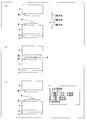
- FIG. 2 is a diagram illustrating a molding operation of the wafer level lens array manufacturing apparatus 1.
- FIG. 3 is a flowchart showing a flow from molding and releasing a wafer level lens array using the wafer level lens array manufacturing method according to one aspect of the present invention.
- a resin part W which is a material to be molded, is disposed on the lower mold ML on the table 9 by, for example, applying or injecting it.
- the temperature (mold temperature) between the upper mold MU and the lower mold ML is a standby temperature, and the resin component W is supplied to the standby temperature (step 101 in FIG. 3, hereinafter abbreviated as S101).
- Alignment of the upper mold MU and the lower mold ML is performed so that the upper mold MU and the lower mold ML appropriately form the molded product with the resin part W interposed therebetween (S102 in FIG. 3).
- the motor control unit 21 lowers the upper mold holding unit 8 in the Z-axis direction (S103 in FIG. 3), thereby contacting the upper mold MU and the resin component W. Then, the resin part W is sandwiched between the upper mold MU and the lower mold ML, and the lowering of the upper mold MU stops (S104 in FIG. 3).
- the pressure control unit 24 controls the force from the servo motor 11 so that the upper mold holding unit 8 and the upper mold MU have a constant pressing pressure P1 (first pressure, initial pressure) vertically downward.
- the control unit 21 is instructed (S105 in FIG. 3). Further, the table 9 and the lower mold ML are given holding force for fixing their positions so as not to move in the X direction and the Y direction by the X axis servo motor mechanism 12 and the Y axis servo motor mechanism 13. .
- the predetermined temperature for example, the mold temperature T2 in FIG. 5
- the predetermined temperature is maintained and the curing reaction of the resin component W proceeds (FIG. 3).
- the upper mold MU and the lower mold ML start to rise toward the set temperature, and keep the temperature constant in order to advance the curing of the resin part W when the set temperature (T2) is reached.
- resin shrinkage also referred to as molding shrinkage
- negative pressure is generated in the upper mold MU and the lower mold ML.
- the pressure control unit 24 instructs the motor control unit 21 to change the set value of the pressing force in the vertically downward direction of the upper mold MU from the pressing pressure P1 to the pressing pressure P2 (first 2 pressure) (see FIG. 6 described later) (S108 in FIG. 3).
- the resin part W is pressed against the upper mold MU and the lower mold ML, and the shapes of the upper mold MU and the lower mold ML are transferred to the resin part W.
- the resin component W is cured.
- Servo-free instruction information which is information indicating that a curing point has been detected, is output to the transmission / reception unit 51.
- the motor control unit 21 releases the holding force of the servo motors 12a and 13a for moving the X axis and Y axis on the table 9 side (makes the servo free) (S110 in FIG. 3).
- the lower mold ML of the table 9 whose holding force is released follows the upper mold MU by the vertical pressing force of the upper mold holding unit 8.
- the timing for making the servo free is determined based on, for example, the resin characteristics (PVT characteristics) shown in FIG.
- the change in the specific volume of the resin part W will be described in detail later.
- the process starts cooling (S111 in FIG. 3).
- a method of turning the lower mold ML and the upper mold MU to cooling at least one of the upper mold holding unit 8 that supports the upper mold MU or the table 9 that supports the lower mold ML is provided with a cooling medium (not shown).
- a method of lowering the mold temperature by supplying (refrigerant) is preferable.
- a means for managing and controlling the temperature and flow rate of the cooling medium is provided. It is desirable to configure.
- the glass transition point (Tg) of the resin part W depends on the reaction rate of the resin part W.
- the resin part W having a reaction rate of 80%
- the resin part W is added to the resin part W until the temperature of the resin part W decreases to about 80 ° C. (glass transition point (Tg): see FIG. 8).
- the applied pressure is reduced from the pressing pressure P2 to the pressing pressure P3 (details will be described later with reference to FIG. 4). At this time, the relative position between the lower mold ML and the upper mold MU is maintained.
- the pressure reduction is not limited to one step from the pressing pressure P2 to the pressing pressure P3, and two or more steps may be performed.
- Cooling is further advanced in a state where the pressing pressure P3 is maintained (S113 in FIG. 3), and desirably, until the temperature of the resin component W is lowered to the release temperature (release point R: see FIG. 8), When the temperature of the resin part W falls below the glass transition point (Tg), the pressing pressure is reduced from the pressing pressure P3 to the pressing pressure P1 (S114 in FIG. 3). During this time, the relative position between the lower mold ML and the upper mold MU is maintained.
- the pressure is not limited to one step from the pressing pressure P3 to the pressing pressure P1, and two or more steps may be performed.
- the pressure (pressing pressure) applied to the resin component W is reduced stepwise. Specifically, the pressing pressure is reduced until the temperature of the resin part W decreases to the glass transition point (Tg), and the temperature of the resin part W further decreases from the glass transition point (Tg) to release the release point R. The pressure is reduced before reaching.
- the motor control unit 21 drives the servo motor 11 as shown in FIG.
- the upper mold holding unit 8 and the upper mold MU are moved vertically upward (S116 in FIG. 3). Thereby, the molded resin part W (molded product) is completed and can be taken out.
- the glass transition point is the temperature at which the resin changes to an amorphous glassy solid.
- the glass transition point is measured as follows, for example.
- the DAC device 50 of the wafer level lens array manufacturing apparatus 1 calculates the reaction rate of the resin component W based on the principle of the differential scanning calorimetry described above.
- the unreacted rate (%) of the resin part W indicates the degree to which the curing reaction of the resin part W is not completed in percent (%).
- FIG. 4 shows the relationship between the unreacted rate (%) of the resin and the glass transition point (° C.).
- the glass transition point is about 80 ° C., and when the unreacted rate is 10% (that is, the reacted rate is 90%). %) Shows that the glass transition point is approximately 115 ° C. Thus, it can be seen that the greater the unreacted rate (%) of the resin part W, the lower the glass transition point Tg, and the relationship between the two is substantially linear.
- the above-described distortion of the resin part W is a main factor that deteriorates the optical properties of the lens when the resin molding made from the resin part W is a lens, for example.
- the temperature of the lower mold ML and the upper mold MU is cooled when the curing reaction rate of the resin component W becomes 80% or more.
- the pressure applied to the resin component W is reduced from the pressing pressure P2 to the pressing pressure P3 at the time before the temperature of the resin component W is cooled to, for example, the glass transition point (Tg).
- the relative position between the lower mold ML and the upper mold MU is maintained.
- the unreacted rate (%) is, for example, a functional group whose structure is changed by a cross-linking reaction between molecules in the chemical structure of the molecule that is the main component of the resin component W (for example, cleaved by cross-linking between molecules). It may be determined by measuring the content of an epoxy ring or the like that disappears.
- the unreacted rate (%) of the resin part W can be obtained as follows. First, the content ⁇ of the functional group R before the start of the curing reaction of the resin part W and the content ⁇ of the functional group R in the resin part W after the curing reaction is completely advanced are measured. The difference ( ⁇ ) in the content of the functional group R before and after the curing reaction is the amount of change in the content of the functional group R when the reaction rate of the curing reaction is 100%. Next, measure the content ⁇ ( ⁇ ⁇ ⁇ ) of the functional group R of the resin part W for which the unreacted rate (%) is to be calculated, and calculate ( ⁇ ) / ( ⁇ ) ⁇ 100. Thus, the unreacted rate (%) of the resin component W can be obtained.
- Raman spectroscopy or infrared spectroscopy is preferably used. can do.
- the wafer level lens array manufacturing apparatus 1 may include means for calculating the reaction rate by a measurement method focusing on the chemical structure of the resin part W as described above, as an alternative to the DSC apparatus 50.
- the intermolecular force is an attractive force acting between molecules on the surface of the mold that contacts the resin and molecules on the surface of the molded product.
- the mold shape is the total area of the contact surface between the mold and the molded product, and the shape of the unevenness provided on the contact surface.
- the vacuum suction force means that when the molded product is peeled from the mold, the air pressure in the gap between the molded product and the mold is lower than the external environment. It is a force that works so as to push in again.
- the electrostatic force is an attractive force by which static electricity generated on both surfaces attracts each other when the molded product is separated from the mold.
- Mold shrinkage is a phenomenon in which the volume of a molded product shrinks when a resin or the like is cured from a liquid state. Compared with the change in the size (for example, volume) of the mold, the contraction of the molded product is large, which causes the molded product to strongly adhere to the unevenness of the mold.
- the most difficult to release the molded product is (5) molding shrinkage.
- the lens may be deformed or broken. Therefore, it is important to release the lens strongly adhered to the mold without causing the lens quality and productivity to deteriorate.
- FIG. 5 shows a reaction rate of a curing reaction of a resin (for example, resin component W, wafer level lens array, etc.) and a mold (for example, the lower mold described above) in the manufacturing process of the wafer level lens array according to an aspect of the present invention. It is the figure which showed typically about the time change of the temperature (mold temperature) of ML and upper mold
- a resin for example, resin component W, wafer level lens array, etc.
- a mold for example, the lower mold described above
- a resin that has not started a curing reaction before heating is applied or injected into a mold (S101 in FIG. 3). Heating is performed between time Z1 and time Z2, and the temperature of the mold is increased from temperature T1 to temperature T2 at a constant temperature increase rate (broken line) (S106 in FIG. 3).
- the curing reaction of the resin in the mold starts and progresses during this temperature rising process.
- FIG. 6 is a diagram schematically showing the time change of the pressure (pressing pressure) applied to the resin and the temperature (mold temperature) of the mold in the manufacturing process of the wafer level lens array shown in FIG.
- a resin that has not started a curing reaction before heating is applied or poured into a mold. Heating is performed between time Z1 and time Z2, and the mold temperature is raised from temperature T1 to temperature T2 at a constant rate of temperature rise (dashed lines in FIGS. 5 and 6). At this time, a pressing pressure P1 is applied to the resin (S105).
- the pressure is increased to the pressing pressure P2 applied to the resin until the time Z3 (see FIG. 5) when the reaction rate of the resin curing reaction reaches 80 to 90% from when this negative pressure is generated, and the resin is applied to the mold. Press firmly. As a result, the shape of the mold is well transferred to the resin (S108 in FIG. 3).
- the mold temperature is lowered and cooling of the resin is started (S111 in FIG. 3).
- the pressure P2 is applied to the resin at time Z3. To the pressing pressure P3 (S112 in FIG. 3).
- the pressure applied to the resin at time Z5 until the cooling of the resin proceeds and the temperature of the resin decreases to the temperature at which the resin is released (release point R in FIG. 8) (S113 in FIG. 3). Is reduced from the pressing pressure P3 to the pressing pressure P1 (S114 in FIG. 3).
- the pressure is gradually reduced from the pressing pressure P2 to the pressing pressure P1.
- a pressing pressure P3 that is an intermediate pressure between the pressing pressure P2 and the pressing pressure P1 is set, and the pressing pressure P2 is changed to the pressing pressure P1.
- An example of reducing the pressure in two stages was shown.
- the method of reducing the pressing pressure in the middle of lowering the mold temperature is not limited to the two-stage pressure reduction exemplified here, and the pressing pressure is reduced in multiple stages (two or more stages). May be.
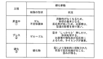
- FIG. 7 is a diagram for explaining the main curing behavior of the resin in each step of pressing and curing during temperature rise in the method for manufacturing the wafer level lens array shown in FIG.
- the resin being heated is a gel or an amorphous solid. Since fluidity is lost, it becomes the basis of the shape of the molded product. Since the reaction rate is still low, the specific volume is susceptible to mold temperature.
- the resin to which a high pressing pressure is applied at a high temperature after the temperature rises is a gel or a rubber.
- FIG. 8 is a diagram showing the relationship between the change in the state of a resin having a property of curing by a molecular cross-linking reaction by heating and the specific volume corresponding to each process of manufacturing a wafer level lens array. .
- the vertical axis in FIG. 8 represents the specific volume of the resin, and the horizontal axis represents the temperature.
- the specific volume is the volume of the resin per unit mass and is the reciprocal of the density of the resin. That is, an increase in specific volume means resin expansion, and conversely, a decrease in specific volume means resin shrinkage.
- a resin is applied or poured into a mold, and the mold is heated to heat the resin (point L).
- the heated resin expands slowly.
- the resin molecules are connected to each other, the degree of freedom of molecular motion is reduced, and the resin gels (point G).
- the glass transition point Tg exists in the middle of resin solidifying (curing point P) from a gel-like state (point G). That is, as shown in FIG. 8, the glass transition point (Tg) of the resin is between point G and point P, and when arranged in order of increasing temperature, point P> Tg> point G.
- the glass transition point Tg is not determined and changes.
- the glass transition point Tg changes so as to increase, as can be seen from the graph of FIG.
- the temperature of the resin part W is cooled from the curing point P, the final curing rate decreases, and as can be seen from the graph of FIG.
- the resin that has become a molded product gradually contracts in the process of cooling from point P to point S. As the cooling proceeds, the temperature of the resin decreases to the temperature at which the resin is released (release point R) (S115 in FIG. 3). The molded product is further cooled from the release point R to the point S to complete the manufacture of the wafer level lens array (S116 in FIG. 3).
- a molded product manufacturing apparatus (wafer level lens array manufacturing apparatus 1) according to an aspect of the present invention includes a molding die (upper mold MU and lower mold ML) for molding a thermosetting resin (resin part W), and the molding mold.
- a molded product manufacturing apparatus comprising a pressure control unit (pressure control unit 24) for controlling a pressure (pressing pressure) to be applied to and a temperature control unit (temperature control unit 31) for controlling the temperature in the mold.
- the pressure control unit is characterized in that the pressure applied to the mold is gradually reduced (S112 and S114).
- the molded product manufacturing method according to one aspect of the present invention is the molded product manufacturing method for manufacturing a molded product by placing a thermosetting resin in a mold and heating and pressurizing. While maintaining a constant temperature, after the molding reaction of the thermosetting resin proceeds, the pressure applied to the mold is gradually reduced during the temperature lowering process in which the temperature of the mold is lowered. It is a feature.
- the pressure control unit applies a second pressure (pressing pressure P2) higher than the first pressure (pressing pressure P1) as an initial pressure at the start of molding.
- the temperature control unit applies heat less than an amount necessary for the thermosetting resin to be completely cured to the thermosetting resin, and the pressure control unit performs the second pressure.
- the temperature control unit cools the mold while applying a third pressure (pressing pressure P3) lower than and higher than the first pressure to the mold.
- heating is stopped at a curing reaction rate necessary for producing a molded product. Then, the pressure applied to the mold is not reduced at once, but is reduced step by step.
- the heating temperature in the mold is maintained at the constant temperature in a state where the second pressure is applied to the mold by the pressure control unit.
- the degree of cure (curing reaction rate, curing reaction rate) of the thermosetting resin that reaches in between is desirably 80% or more and less than 100%.
- the temperature control unit causes the temperature in the mold to vary from a certain temperature to a glass transition temperature (glass) corresponding to the degree of curing of the thermosetting resin.
- the pressure control unit reduces the pressure applied to the mold from the second pressure to the third pressure by at least one stage until it is cooled to the transition point (Tg)). It is desirable to do.
- At least 1 pressure is applied to the molded product before the temperature of the resin cured in the mold after the temperature starts to decrease is lower than the glass transition temperature of the resin. Perform staged pressure reduction.
- the molded product is a lens
- the temperature lowering process until the molded product after being cured is cooled and released from mold, the generation and remaining of distortion, which are the main factors that deteriorate the optical properties, or Mitigation can be suitably performed.
- the pressure control unit preferably performs at least one level of pressure reduction so as to reduce the pressure applied to the mold from the third pressure to the first pressure.
- the pressure applied to the molded article can be suitably reduced, and an excessive pressure is applied to the resin component W having a high elastic modulus. This can be avoided accurately.
- the pressure control unit reduces the pressure applied to the mold from the second pressure to the third pressure when reducing the pressure from the second pressure to the first pressure. After the pressure is reduced, it is preferable to perform at least two steps of reduction so as to reduce the third pressure to the first pressure.
- the pressure applied to the mold can be suitably reduced rather than reduced all at once.
- the molded product can be released smoothly and easily without degrading the quality and productivity of the molded product.
- each block of the wafer level lens array manufacturing apparatus 1, particularly the control unit 20, and the calorific value calculation unit 53 and the reaction rate calculation unit 54 included in the DSC apparatus 50 are formed on an integrated circuit (IC chip).
- IC chip integrated circuit
- it may be realized by hardware using a logic circuit, or may be realized by software using a CPU (Central Processing Unit).
- the wafer level lens array manufacturing apparatus 1 includes a CPU that executes program instructions for realizing each function, a ROM (Read Only Memory) that stores the program, a RAM (Random Access Memory) that expands the program, A storage device (recording medium) such as a memory for storing the program and various data is provided.
- the object of the present invention is to record the program code (execution format program, intermediate code program, source program) of the control program of the wafer level lens array manufacturing apparatus 1 which is software for realizing the above-described functions so that it can be read by a computer. This can also be achieved by supplying a recording medium to the wafer level lens array manufacturing apparatus 1 and reading and executing the program code recorded on the recording medium by the computer (or CPU or MPU).
- Examples of the recording medium include non-transitory tangible media, such as magnetic tapes and cassette tapes, magnetic disks such as floppy (registered trademark) disks / hard disks, and CD-ROM / MO.
- Discs including optical disks such as / MD / DVD / CD-R, cards such as IC cards (including memory cards) / optical cards, and semiconductor memories such as mask ROM / EPROM / EEPROM (registered trademark) / flash ROM
- logic circuits such as PLD (Programmable logic device) and FPGA (Field Programmable Gate array) can be used.
- the wafer level lens array manufacturing apparatus 1 may be configured to be connectable to a communication network, and the program code may be supplied via the communication network.
- the communication network is not particularly limited as long as it can transmit the program code.
- the Internet intranet, extranet, LAN, ISDN, VAN, CATV communication network, virtual private network (Virtual Private Network), telephone line network, mobile communication network, satellite communication network, etc. can be used.
- the transmission medium constituting the communication network may be any medium that can transmit the program code, and is not limited to a specific configuration or type.
- wired lines such as IEEE 1394, USB, power line carrier, cable TV line, telephone line, ADSL (Asymmetric Digital Subscriber Line) line, infrared rays such as IrDA and remote control, Bluetooth (registered trademark), IEEE 802.11 wireless, HDR ( It can also be used wirelessly such as High Data Rate, NFC (Near Field Communication), DLNA (registered trademark) (Digital Living Network Alliance), mobile phone network, satellite line, and digital terrestrial network.
- the present invention can also be realized in the form of a computer data signal embedded in a carrier wave in which the program code is embodied by electronic transmission.
- the present invention can be used in a technique for mass-producing a molded product having a predetermined shape using a molding die.
Landscapes
- Engineering & Computer Science (AREA)
- Mechanical Engineering (AREA)
- Physics & Mathematics (AREA)
- Health & Medical Sciences (AREA)
- Oral & Maxillofacial Surgery (AREA)
- Thermal Sciences (AREA)
- Casting Or Compression Moulding Of Plastics Or The Like (AREA)
- Moulds For Moulding Plastics Or The Like (AREA)
Abstract
Description
(ウェハレベルレンズアレイ製造装置の概略構成)
図1を用いてウェハレベルレンズアレイ製造装置1の構成について説明する。図1は、DSC(示差走査熱量測定)装置50を備える、本実施の形態に係るウェハレベルレンズアレイ製造装置1の構成例を表す図である。
(反応率)=(1-(発熱量SAM)/(発熱量REF))×100 (式1)
そして、反応率演算部54は、反応率の算出結果が80%以上となると、樹脂部品Wは硬化したと見なし、硬化点を検出した旨の情報であるサーボフリー指示情報を送受信部51に出力する。
次に、図2、および図3を用いてウェハレベルレンズアレイ製造装置1の動作の概略について説明する。
ここでは、図4を用いて、樹脂部品Wの未反応率(%)と、ガラス転移点(℃)とについて簡単に説明する。その前に、まず、ガラス転移点、および未反応率について簡単に説明する。
成形物(例えば、樹脂部品W,ウェハレベルレンズアレイなど)を成形型(例えば、前述の下型MLおよび上型MU)に対して強く付着させて、成形物の離型を困難にする原因として、(1)分子間力、(2)金型形状、(3)真空吸引力、(4)静電気力、(5)成形収縮、などが挙げられる。
図5と図6を用いて、ウェハレベルレンズアレイの製造方法の実施例を説明する。
図7は、図6に記載のウェハレベルレンズアレイ製造方法における、昇温中、プレス、硬化の各工程における樹脂の主な硬化挙動を説明する図である。
本発明の一態様に係る成形物製造装置(ウェハレベルレンズアレイ製造装置1)は、熱硬化性樹脂(樹脂部品W)を成形する成形型(上型MUおよび下型ML)と、上記成形型に加える圧力(押し圧)を制御する圧力制御部(圧力制御部24)と、上記成形型内の温度を制御する温度制御部(温度制御部31)とを備えた成形物製造装置において、上記温度制御部によって、上記成形型内の加熱温度を一定温度(温度T2)に保持しながら、上記熱硬化性樹脂の硬化反応を進ませ成形した後、成形型内の温度を下降させる温度降下工程中に、上記圧力制御部は、上記成形型に加えていた圧力を段階的に減じる(S112およびS114)ことを特徴としている。
最後に、ウェハレベルレンズアレイ製造装置1の各ブロック、特に制御部20と、DSC装置50に含まれる発熱量演算部53および反応率演算部54とは、集積回路(ICチップ)上に形成された論理回路によってハードウェア的に実現してもよいし、CPU(Central Processing Unit)を用いてソフトウェア的に実現してもよい。
6 ボールネジ
8 上型保持部
9 テーブル
11 サーボモータ(第1の駆動部)
12a・13a サーボモータ(第2の駆動部)
12b・13b リニアスケール
15 ロードセル
20 制御部
21 モータ制御部
22 押し圧低減指示部
24 圧力制御部
25 タイマー
26 ガラス転移点演算部
31 温度制御部
41 位置検出部(硬化判定部)
50 DSC装置
51 送受信部
52 記憶部
53 発熱量演算部
54 反応率演算部(硬化判定部)
ML 下型(成形型)
MU 上型(成形型)
P 硬化点
R 離型点
Tg ガラス転移点
W 樹脂部品(熱硬化性樹脂)
P1 押し圧(第1圧力、初期圧力)
P2 押し圧(第2圧力)
P3 押し圧(第3圧力)
Claims (7)
- 熱硬化性樹脂を成形する成形型と、上記成形型に加える圧力を制御する圧力制御部と、上記成形型内の温度を制御する温度制御部とを備えた成形物製造装置において、
上記温度制御部によって、上記成形型内の加熱温度を一定温度に保持しながら、上記熱硬化性樹脂の硬化反応を進ませ成形した後、成形型内の温度を下降させる温度降下工程中に、
上記圧力制御部は、上記成形型に加えていた圧力を段階的に減じることを特徴とする成形物製造装置。 - 成形開始時の初期圧力としての第1圧力よりも高い第2圧力を上記圧力制御部によって上記成形型に加えた状態で、上記温度制御部は、上記熱硬化性樹脂が完全に硬化するために必要な量未満の熱を上記熱硬化性樹脂に加え、
上記圧力制御部が、上記第2圧力よりも低く、かつ上記第1圧力よりも高い、第3圧力を上記成形型に加えながら、上記温度制御部が上記成形型を冷却することを特徴とする、請求項1に記載の成形物製造装置。 - 上記圧力制御部によって上記第2圧力を上記成形型に加えた状態で、上記成形型内の加熱温度を上記一定温度に保持している間に到達する上記熱硬化性樹脂の硬化度は、80%以上100%未満であることを特徴とする、請求項2に記載の成形物製造装置。
- 上記温度制御部によって、上記成形型内の温度が、上記一定温度から上記熱硬化性樹脂の上記硬化度に対応したガラス転移温度にまで冷却されるまでの間に、上記圧力制御部は、上記成形型に加える圧力を上記第2圧力から上記第3圧力へ低減するように、少なくとも1段階の圧力低減を行うことを特徴とする、請求項3に記載の成形物製造装置。
- 上記温度制御部によって、上記成形型内の温度が、上記熱硬化性樹脂の上記硬化度に対応したガラス転移温度を下回ったときに、上記圧力制御部は、上記成形型に加える圧力を上記第3圧力から上記第1圧力へ低減するように、少なくとも1段階の圧力低減を行うことを特徴とする、請求項3または4に記載の成形物製造装置。
- 上記圧力制御部は、上記成形型に加える圧力を上記第2圧力から上記第1圧力へ低減するにあたって、上記第2圧力から上記第3圧力へ低減した後、上記第3圧力から第1圧力へ低減するように、少なくとも2段階の低減を行うことを特徴とする、請求項2から5のいずれか1項に記載の成形物製造装置。
- 熱硬化性樹脂を成形型に入れて加熱および加圧することによって、成形物を製造する成形物製造方法において、
上記成形型の加熱温度を一定温度に保持しながら、上記熱硬化性樹脂の硬化反応を進ませ成形した後、成形型の温度を下降させる温度降下工程中に、上記成形型に加えていた圧力を段階的に減じることを特徴とする成形物製造方法。
Priority Applications (3)
| Application Number | Priority Date | Filing Date | Title |
|---|---|---|---|
| CN201380004091.XA CN103958150B (zh) | 2012-11-09 | 2013-10-04 | 成形物制造装置以及成形物制造方法 |
| US14/353,703 US9452554B2 (en) | 2012-11-09 | 2013-10-04 | Molded product manufacturing apparatus, and molded product manufacturing method |
| JP2014508413A JP5538640B1 (ja) | 2012-11-09 | 2013-10-04 | 成形物製造装置、および成形物製造方法 |
Applications Claiming Priority (2)
| Application Number | Priority Date | Filing Date | Title |
|---|---|---|---|
| JP2012247845 | 2012-11-09 | ||
| JP2012-247845 | 2012-11-09 |
Publications (1)
| Publication Number | Publication Date |
|---|---|
| WO2014073304A1 true WO2014073304A1 (ja) | 2014-05-15 |
Family
ID=50684421
Family Applications (1)
| Application Number | Title | Priority Date | Filing Date |
|---|---|---|---|
| PCT/JP2013/077166 Ceased WO2014073304A1 (ja) | 2012-11-09 | 2013-10-04 | 成形物製造装置、および成形物製造方法 |
Country Status (5)
| Country | Link |
|---|---|
| US (1) | US9452554B2 (ja) |
| JP (1) | JP5538640B1 (ja) |
| CN (1) | CN103958150B (ja) |
| TW (1) | TWI474914B (ja) |
| WO (1) | WO2014073304A1 (ja) |
Families Citing this family (11)
| Publication number | Priority date | Publication date | Assignee | Title |
|---|---|---|---|---|
| GB2554218A (en) * | 2015-03-17 | 2018-03-28 | Harvard College | Automated membrane fabrication system |
| KR102266461B1 (ko) * | 2015-06-08 | 2021-06-17 | 닛코-매터리얼즈 가부시키가이샤 | 적층 장치 |
| JP6710107B2 (ja) * | 2016-06-10 | 2020-06-17 | アサヒ・エンジニアリング株式会社 | 樹脂封止装置 |
| US10773430B2 (en) | 2017-04-25 | 2020-09-15 | The Boeing Company | Thermoplastic composite part manufacturing system and method |
| TWI725300B (zh) * | 2018-04-10 | 2021-04-21 | 中原大學 | 射出成型設備及射出成型方法 |
| CN109483782A (zh) * | 2018-12-04 | 2019-03-19 | 威海光威复合材料股份有限公司 | 橡胶态树脂浇铸体制备方法 |
| JP6717517B1 (ja) * | 2020-01-08 | 2020-07-01 | 株式会社浅野研究所 | 熱成形装置 |
| JP6736117B1 (ja) * | 2020-02-20 | 2020-08-05 | 株式会社浅野研究所 | 熱成形装置 |
| US11485124B1 (en) * | 2021-07-29 | 2022-11-01 | Nikko-Materials Co., Ltd. | Laminating apparatus and laminating method using same |
| JP7360426B2 (ja) * | 2021-08-12 | 2023-10-12 | Towa株式会社 | 樹脂成形装置、及び樹脂成形品の製造方法 |
| CN119546435A (zh) * | 2022-06-03 | 2025-02-28 | 迈图高新材料有限责任公司 | 通过模塑或挤出的部件生产及系统 |
Citations (5)
| Publication number | Priority date | Publication date | Assignee | Title |
|---|---|---|---|---|
| JPS6038117A (ja) * | 1983-08-11 | 1985-02-27 | Inax Corp | 熱硬化性樹脂材料の成形進行状態の検知方法及びこの検知方法を用いた成形制御方法並びに成形装置 |
| JP2008200928A (ja) * | 2007-02-19 | 2008-09-04 | Konica Minolta Opto Inc | 樹脂の成形方法及び樹脂成形物 |
| JP2010264652A (ja) * | 2009-05-14 | 2010-11-25 | Fujifilm Corp | 造形物の製造方法及び製造装置 |
| JP2013006398A (ja) * | 2011-06-27 | 2013-01-10 | Fujifilm Corp | 成形装置及び成形方法 |
| JP2013075499A (ja) * | 2011-09-30 | 2013-04-25 | Sharp Corp | 光学素子の製造装置および製造方法、並びに制御プログラム |
Family Cites Families (9)
| Publication number | Priority date | Publication date | Assignee | Title |
|---|---|---|---|---|
| CA1284007C (en) * | 1986-02-13 | 1991-05-14 | Robert V. Kromrey | Molding method and apparatus using a solid, flowable, polymer medium |
| US4940563A (en) * | 1986-02-13 | 1990-07-10 | United Technologies Corporation | Molding method and apparatus using a solid flowable, polymer medium |
| JP3935406B2 (ja) | 2002-08-12 | 2007-06-20 | シチズン電子株式会社 | 樹脂成形品の離型方法 |
| JP4672635B2 (ja) * | 2006-11-01 | 2011-04-20 | トヨタ自動車株式会社 | 樹脂封止方法及びモータ |
| JP5202361B2 (ja) | 2009-01-29 | 2013-06-05 | シャープ株式会社 | 成形方法、成形装置、成形金型、光学素子アレイ板の製造方法、電子素子モジュールの製造方法、電子情報機器 |
| JP5401168B2 (ja) | 2009-05-14 | 2014-01-29 | 富士フイルム株式会社 | ウェハレベルレンズアレイの製造方法、ウェハレベルレンズアレイ、レンズモジュール及び撮像ユニット |
| JP5390357B2 (ja) | 2009-12-04 | 2014-01-15 | パナソニック株式会社 | 光学レンズ用プレス成形金型、ガラス製光学レンズ、及びガラス製光学レンズの製造方法 |
| GB201000138D0 (en) * | 2010-01-06 | 2010-02-24 | Seddon Mark | Moulded plastic articles and method and apparatus of moulding thermosetting plastics |
| JP5292445B2 (ja) * | 2010-11-26 | 2013-09-18 | 株式会社芦田製作所 | オートクレーブ成形方法及びオートクレーブ成形装置 |
-
2013
- 2013-10-04 CN CN201380004091.XA patent/CN103958150B/zh active Active
- 2013-10-04 US US14/353,703 patent/US9452554B2/en active Active
- 2013-10-04 WO PCT/JP2013/077166 patent/WO2014073304A1/ja not_active Ceased
- 2013-10-04 JP JP2014508413A patent/JP5538640B1/ja not_active Expired - Fee Related
- 2013-10-16 TW TW102137359A patent/TWI474914B/zh active
Patent Citations (5)
| Publication number | Priority date | Publication date | Assignee | Title |
|---|---|---|---|---|
| JPS6038117A (ja) * | 1983-08-11 | 1985-02-27 | Inax Corp | 熱硬化性樹脂材料の成形進行状態の検知方法及びこの検知方法を用いた成形制御方法並びに成形装置 |
| JP2008200928A (ja) * | 2007-02-19 | 2008-09-04 | Konica Minolta Opto Inc | 樹脂の成形方法及び樹脂成形物 |
| JP2010264652A (ja) * | 2009-05-14 | 2010-11-25 | Fujifilm Corp | 造形物の製造方法及び製造装置 |
| JP2013006398A (ja) * | 2011-06-27 | 2013-01-10 | Fujifilm Corp | 成形装置及び成形方法 |
| JP2013075499A (ja) * | 2011-09-30 | 2013-04-25 | Sharp Corp | 光学素子の製造装置および製造方法、並びに制御プログラム |
Also Published As
| Publication number | Publication date |
|---|---|
| JP5538640B1 (ja) | 2014-07-02 |
| CN103958150B (zh) | 2017-09-19 |
| JPWO2014073304A1 (ja) | 2016-09-08 |
| TW201420308A (zh) | 2014-06-01 |
| US20150021829A1 (en) | 2015-01-22 |
| US9452554B2 (en) | 2016-09-27 |
| TWI474914B (zh) | 2015-03-01 |
| CN103958150A (zh) | 2014-07-30 |
Similar Documents
| Publication | Publication Date | Title |
|---|---|---|
| JP5538640B1 (ja) | 成形物製造装置、および成形物製造方法 | |
| CN104582940B (zh) | 退火方法、退火夹具和退火装置 | |
| JP4022923B2 (ja) | 光学素子の成形方法 | |
| CN101574840B (zh) | 模仁的制造方法 | |
| CN1778729B (zh) | 非球面模造玻璃制造方法及其装置 | |
| JP5623673B2 (ja) | 成型装置、成型装置ユニット及び成形方法 | |
| CN116639866A (zh) | 非等温步进式热压方法及步进式热压装置 | |
| Zhou et al. | Study on nonisothermal glass molding press for aspherical lens | |
| JP4781001B2 (ja) | 複合レンズの製造方法 | |
| JP2013014455A (ja) | ガラス光学素子の製造方法 | |
| JP2016010950A (ja) | 光学素子の製造システム、光学素子の製造方法、及びプログラム | |
| CN114685033A (zh) | 通过获得温度的标定曲线进行模压的方法 | |
| JP2013075499A (ja) | 光学素子の製造装置および製造方法、並びに制御プログラム | |
| Yin et al. | Numerical simulation on two-step isothermal glass lens molding | |
| JP6032951B2 (ja) | 光学素子の製造方法 | |
| JP5724156B2 (ja) | インプリント方法 | |
| US8641934B2 (en) | Method for fabricating light guide plate | |
| JPH02196039A (ja) | ガラス光学素子の成形方法 | |
| JP2819866B2 (ja) | ガラスレンズ成形装置およびその熱緩衝材 | |
| JP2004331471A (ja) | 光学素子の成形方法及び成形装置 | |
| JP2006206394A (ja) | 光学素子成形型およびその製造方法、並びにこれを用いた光学素子の製造方法 | |
| Kang et al. | Design and fabrication of micro optical components for optical data storage by micromolding | |
| TWI232207B (en) | Core removal method for precision glass molding and molding device | |
| JPH10180893A (ja) | プラスチックレンズとその製造方法及び装置 | |
| JP5372071B2 (ja) | 微細構造転写成形方法 |
Legal Events
| Date | Code | Title | Description |
|---|---|---|---|
| ENP | Entry into the national phase |
Ref document number: 2014508413 Country of ref document: JP Kind code of ref document: A |
|
| WWE | Wipo information: entry into national phase |
Ref document number: 14353703 Country of ref document: US |
|
| 121 | Ep: the epo has been informed by wipo that ep was designated in this application |
Ref document number: 13854116 Country of ref document: EP Kind code of ref document: A1 |
|
| NENP | Non-entry into the national phase |
Ref country code: DE |
|
| 122 | Ep: pct application non-entry in european phase |
Ref document number: 13854116 Country of ref document: EP Kind code of ref document: A1 |