WO2014073147A1 - サファイア単結晶の製造方法及び種結晶 - Google Patents
サファイア単結晶の製造方法及び種結晶 Download PDFInfo
- Publication number
- WO2014073147A1 WO2014073147A1 PCT/JP2013/005830 JP2013005830W WO2014073147A1 WO 2014073147 A1 WO2014073147 A1 WO 2014073147A1 JP 2013005830 W JP2013005830 W JP 2013005830W WO 2014073147 A1 WO2014073147 A1 WO 2014073147A1
- Authority
- WO
- WIPO (PCT)
- Prior art keywords
- seed crystal
- crystal
- single crystal
- melt
- sapphire single
- Prior art date
- Legal status (The legal status is an assumption and is not a legal conclusion. Google has not performed a legal analysis and makes no representation as to the accuracy of the status listed.)
- Ceased
Links
Images



Classifications
-
- C—CHEMISTRY; METALLURGY
- C30—CRYSTAL GROWTH
- C30B—SINGLE-CRYSTAL GROWTH; UNIDIRECTIONAL SOLIDIFICATION OF EUTECTIC MATERIAL OR UNIDIRECTIONAL DEMIXING OF EUTECTOID MATERIAL; REFINING BY ZONE-MELTING OF MATERIAL; PRODUCTION OF A HOMOGENEOUS POLYCRYSTALLINE MATERIAL WITH DEFINED STRUCTURE; SINGLE CRYSTALS OR HOMOGENEOUS POLYCRYSTALLINE MATERIAL WITH DEFINED STRUCTURE; AFTER-TREATMENT OF SINGLE CRYSTALS OR A HOMOGENEOUS POLYCRYSTALLINE MATERIAL WITH DEFINED STRUCTURE; APPARATUS THEREFOR
- C30B15/00—Single-crystal growth by pulling from a melt, e.g. Czochralski method
- C30B15/36—Single-crystal growth by pulling from a melt, e.g. Czochralski method characterised by the seed, e.g. its crystallographic orientation
-
- C—CHEMISTRY; METALLURGY
- C30—CRYSTAL GROWTH
- C30B—SINGLE-CRYSTAL GROWTH; UNIDIRECTIONAL SOLIDIFICATION OF EUTECTIC MATERIAL OR UNIDIRECTIONAL DEMIXING OF EUTECTOID MATERIAL; REFINING BY ZONE-MELTING OF MATERIAL; PRODUCTION OF A HOMOGENEOUS POLYCRYSTALLINE MATERIAL WITH DEFINED STRUCTURE; SINGLE CRYSTALS OR HOMOGENEOUS POLYCRYSTALLINE MATERIAL WITH DEFINED STRUCTURE; AFTER-TREATMENT OF SINGLE CRYSTALS OR A HOMOGENEOUS POLYCRYSTALLINE MATERIAL WITH DEFINED STRUCTURE; APPARATUS THEREFOR
- C30B29/00—Single crystals or homogeneous polycrystalline material with defined structure characterised by the material or by their shape
- C30B29/10—Inorganic compounds or compositions
- C30B29/16—Oxides
- C30B29/20—Aluminium oxides
-
- C—CHEMISTRY; METALLURGY
- C30—CRYSTAL GROWTH
- C30B—SINGLE-CRYSTAL GROWTH; UNIDIRECTIONAL SOLIDIFICATION OF EUTECTIC MATERIAL OR UNIDIRECTIONAL DEMIXING OF EUTECTOID MATERIAL; REFINING BY ZONE-MELTING OF MATERIAL; PRODUCTION OF A HOMOGENEOUS POLYCRYSTALLINE MATERIAL WITH DEFINED STRUCTURE; SINGLE CRYSTALS OR HOMOGENEOUS POLYCRYSTALLINE MATERIAL WITH DEFINED STRUCTURE; AFTER-TREATMENT OF SINGLE CRYSTALS OR A HOMOGENEOUS POLYCRYSTALLINE MATERIAL WITH DEFINED STRUCTURE; APPARATUS THEREFOR
- C30B15/00—Single-crystal growth by pulling from a melt, e.g. Czochralski method
- C30B15/10—Crucibles or containers for supporting the melt
Definitions
- the present invention relates to a method for producing a sapphire single crystal by the Czochralski method (CZ method).
- the heating method is exclusively high-frequency heating.
- an oxide heat insulating material such as zirconia or alumina is used.
- the high melting point metal having high oxidation resistance used for the crucible is limited to very expensive iridium, the yield of the c-axis crystal is high but the cost is high.
- Patent Document 1 In case of changing to tungsten or molybdenum crucible to reduce the cost in the CZ method capable of producing c-axis crystals (Patent Document 1), use a carbon-based heat insulating material because it has lower oxidation resistance than iridium. become. Since carbon is a good conductor, the high-frequency heating method has poor thermal efficiency and inevitably uses a resistance heater.
- the temperature inside the furnace is equalized to a temperature higher than that of the melt and the crucible, compared to high-frequency heating in which only the iridium crucible is directly heated.
- a seed crystal cut out from a sapphire single crystal with a band saw or a wire saw is placed in the melt and then pulled up. At this time, in the case where the melt is heated by the resistance heater as described above, there is a problem that it melts not from the bottom surface of the seed crystal but from the side surface before landing on the melt.
- the surface roughness of the cutting surface of the seed crystal is several ⁇ m and is in a semitransparent state.
- the sapphire single crystal is originally colorless and transparent as used as an optical material, and is a material having a very high infrared transmittance even in a temperature range exceeding 2000 ° C.
- the surface is rough, it is easy to absorb infrared rays on the surface of the seed crystal, so even if the melt temperature is adjusted to the optimum temperature for seeding, it is not the bottom of the seed crystal before landing on the melt.
- the present inventors have found that it melts from the side.
- the present invention has been made in view of the above problems, and when a sapphire single crystal is manufactured by an apparatus using a resistance heater, it is seeded well so that the seed crystal does not melt before landing.
- An object is to provide a method capable of
- the present invention provides a melt obtained by heating and melting a raw material with a resistance heater in a crucible mainly composed of tungsten or molybdenum or both tungsten and molybdenum by the CZ method.
- a method for producing a sapphire single crystal by depositing and pulling a seed crystal, wherein the seed crystal that has been ground is used as the seed crystal to be deposited on the melt.
- a method for producing a single crystal is provided.
- the transmittance of infrared rays from the resistance heater is high, so that the seed crystal melts before landing without causing the seed crystal to rise in temperature. Therefore, the productivity of the sapphire single crystal can be improved.
- a seed crystal whose side surface is polished is used as a seed crystal to be deposited on the melt.
- a seed crystal with such a side polished the endotherm on the side surface is suppressed, and the side surface melts down before landing and melting the seed crystal more effectively. can do.
- a seed crystal whose entire surface is polished as a seed crystal to be deposited on the melt.
- the infrared transmittance is further increased, and it is possible to reliably prevent the seed crystal from being melted before landing.
- a seed crystal that has been subjected to polishing and has a surface roughness Ra value of 100 nm or less as a seed crystal to be deposited on the melt.
- the present invention also provides a seed crystal used when producing a sapphire single crystal by the CZ method, wherein the seed crystal has been subjected to polishing.
- the surface on which the seed crystal has been polished preferably has a surface roughness Ra value of 100 nm or less.
- Such surface roughness provides a seed crystal that has a sufficiently high infrared transmittance and can more effectively prevent melting by heat.
- FIG. 4 shows the transmittance of sapphire by wavelength range.
- FIG. 5 shows the temperature dependence of the absorption coefficient of sapphire. As shown in FIG. 4, at room temperature, sapphire has a transmittance of about 85% in the wavelength range of 0.5 ⁇ m to 5 ⁇ m. Moreover, as shown in FIG. 5, although it will become easy to absorb if temperature rises, it still has very little absorbed heat. However, in the case of a seed crystal cut out from a band saw or a wire saw, it is considered that infrared rays do not easily transmit because the surface is rough, and the surface layer temperature becomes high, resulting in melting damage.
- the inventors have performed a polishing process using, for example, diamond abrasive grains on the cut seed crystal, thereby suppressing infrared absorption on the surface of the seed crystal, thereby preventing melting.
- the present invention has been completed by finding that it can be prevented.
- FIG. 1 is a schematic view showing an example of the seed crystal of the present invention.
- a seed crystal is deposited on a melt obtained by heating and melting a raw material with a resistance heater in a crucible mainly composed of tungsten or molybdenum or both tungsten and molybdenum by the CZ method. This is a method for producing a sapphire single crystal by pulling up.
- a seed crystal that has been subjected to polishing is used as the seed crystal that is deposited on the melt.
- the infrared transmittance from the resistance heater can be increased close to the original transmittance of sapphire.
- a cuboid single crystal as shown in FIG. 1 is cut out from a sapphire single crystal with a band saw or a wire saw, and the surface thereof is polished by a polishing apparatus using, for example, diamond abrasive grains.
- Crystal 10 is assumed.
- the shape of the seed crystal is not limited to this, and a cylindrical shape or the like can also be used.
- a seed crystal 10 whose side surface is polished.
- the side surface is easy to receive heat from the resistance heater, and when the side surface melts, the bottom of the seed crystal melts together with the bottom surface on which the liquid is deposited. For example, by polishing only the side surface, Melting loss can be prevented.
- a seed crystal 10 whose entire surface is polished.
- the infrared transmittance of the seed crystal can be further increased, and melting damage can be more effectively prevented.
- a seed crystal that has been subjected to polishing and has a surface roughness Ra value of 100 nm or less, particularly 10 nm or less. With such a surface roughness, the infrared transmittance is sufficiently high, and the seed crystal can be more effectively prevented from being melted by the heat from the resistance heater.
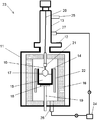
- a single crystal manufacturing apparatus as shown in FIG. 2 can be used.
- the single crystal manufacturing apparatus 23 of FIG. 2 is an apparatus that pulls up and manufactures the sapphire single crystal 17 from the melt 15 obtained by heating and melting the alumina raw material in the crucible 14 by the CZ method.
- the crucible 14 is mainly composed of tungsten or molybdenum, or both tungsten and molybdenum. These are cheaper than iridium and are advantageous for cost reduction.
- the single crystal manufacturing apparatus 23 includes a crucible 14 in the main chamber 11 and a resistance heater 22 that surrounds the crucible 14 and heats the raw material in the crucible 14. Furthermore, a pull chamber 13 connected to the main chamber 11 so as to be partitioned by a gate valve 12 may be provided. By having such a pull chamber 13, the raw material can be charged without turning off the power of the resistance heater 22.
- the single crystal manufacturing apparatus 23 includes a gas introduction pipe 25 and a gas discharge pipe 26.
- a gas introduction pipe 25 For example, during operation such as single crystal growth, inert gas or the like is supplied from above the pull chamber 13.
- the gas is introduced into the furnace through the gas introduction pipe 25, and the introduced gas can be discharged out of the furnace from the gas discharge pipe 26 at the bottom of the main chamber 11 by the vacuum pump 24 or the like.
- the gate valve 12 is closed and the work is performed in the pull chamber 13, and then the gas in the pull chamber 13 is replaced by using the gas discharge pipe 27 and the gas introduction pipe 25 for the pull chamber. Then, by setting the pull chamber 13 to the same condition as the main chamber 11 and then opening the gate valve 12, the single crystal growth step can be performed subsequently.
- the single crystal manufacturing apparatus 23 includes a heat insulating material 16 such as a graphite felt material surrounding the crucible 14 and the resistance heater 22, a pulling shaft 20 used for pulling up the sapphire single crystal 17, and a seed holder for holding the seed crystal 10. 21, a metal holder 18 such as molybdenum that supports the crucible 14, and a crucible support shaft 19 made of, for example, molybdenum that supports the crucible 14 via a metal holder 18 such as molybdenum.
- a heat insulating material 16 such as a graphite felt material surrounding the crucible 14 and the resistance heater 22
- a pulling shaft 20 used for pulling up the sapphire single crystal 17
- a seed holder for holding the seed crystal 10.
- a metal holder 18 such as molybdenum that supports the crucible 14
- a crucible support shaft 19 made of, for example, molybdenum that supports the crucible 14 via a metal holder 18 such as molybdenum.
- the sapphire single crystal 17 can be grown by using the single crystal production apparatus 23 as described above to attach the seed crystal 10 of the present invention to the melt 15 and pull it up. According to the present invention, even if the temperature distribution using the resistance heater 22 is easy to be uniform in the furnace, it is possible to effectively prevent the seed crystal 10 from being melted during seeding. The yield can be improved.
- Example and a comparative example are shown and this invention is demonstrated more concretely, this invention is not limited to these.
- Examples and comparative examples Using the apparatus shown in FIG. 2, a molybdenum crucible containing 15 kg of high-purity alumina is set in a furnace using isotropic graphite and carbon fiber molded heat insulating material, and heated and melted with a resistance heater. did. Thereafter, a 10-mm square ⁇ 100-mm long cuboidal c-axis seed crystal was slowly lowered and seeded by landing.
- Two types of seed crystals are used, one having a cut surface as it is (Comparative Example) and one having a polished surface obtained by polishing with diamond abrasive grains on the cut surface (Example).
- the temperature of the seed crystal was changed at three levels to compare the erosion status of the seed crystals. The results are shown in Table 1.
- the surface roughness of the polished surface was about 10 nm in terms of Ra value.
- the optimum temperature of the melt in Table 1 means the melt temperature at which a meniscus is formed after seeding and the crystal does not grow in the radial direction thereafter.
- the present invention is not limited to the above embodiment.
- the above-described embodiment is an exemplification, and the present invention has substantially the same configuration as the technical idea described in the claims of the present invention, and any device that exhibits the same function and effect is the present invention. It is included in the technical scope of the invention.
Landscapes
- Chemical & Material Sciences (AREA)
- Engineering & Computer Science (AREA)
- Crystallography & Structural Chemistry (AREA)
- Materials Engineering (AREA)
- Metallurgy (AREA)
- Organic Chemistry (AREA)
- Inorganic Chemistry (AREA)
- Crystals, And After-Treatments Of Crystals (AREA)
Abstract
本発明は、CZ法により、タングステン又はモリブデン、あるいはタングステンとモリブデンの両方を主成分とするルツボ内で原料を抵抗加熱ヒータによって加熱溶融して得られた融液に、種結晶を着液させて引上げることによりサファイア単結晶を製造する方法であって、前記融液に着液させる種結晶として、研磨加工が施された種結晶を用いるサファイア単結晶の製造方法である。これにより、抵抗加熱ヒータを用いた装置によりサファイア単結晶を製造する際に、側面等が溶けないように種結晶を良好に種付けすることができる方法が提供される。
Description
本発明は、チョクラルスキー法(CZ法)によりサファイア単結晶を製造する方法に関する。
サファイア単結晶の製造方法には様々なものがある。Kyropoulos法は、タングステンもしくはモリブデンルツボに高純度アルミナを入れ、その外側に配置した抵抗加熱ヒータで溶融を行った後、融液の上方からサファイア単結晶の種結晶を下降させて着液し、以後、温度を徐々に低下させることで種結晶から下方に単結晶を成長させる方法である。
この方法は原料全てを単結晶化させるため、非常に歩留まりの高い製法ではあるが、GaN基板に用いられるc軸結晶の製作が難しいため、一般にはa軸結晶を製作した後、a軸と垂直なc軸にインゴットを刳り抜く作業が必要となり、このため、LED用c軸結晶基板を製造する場合には、その歩留まりは低くなってしまう。
この方法は原料全てを単結晶化させるため、非常に歩留まりの高い製法ではあるが、GaN基板に用いられるc軸結晶の製作が難しいため、一般にはa軸結晶を製作した後、a軸と垂直なc軸にインゴットを刳り抜く作業が必要となり、このため、LED用c軸結晶基板を製造する場合には、その歩留まりは低くなってしまう。
一方、c軸結晶の製造が可能なCZ法においては、その加熱方式は専ら高周波加熱である。この方法では金属ルツボのみを発熱させるため、ジルコニアやアルミナといった酸化物系の断熱材が使用される。その場合、ルツボに使用される耐酸化性の高い高融点金属は非常に高価なイリジウムに限定されるため、c軸結晶の歩留まりは高いが、高コストになっていた。
c軸結晶の製造が可能なCZ法において、そのコストを下げるためタングステンやモリブデンルツボに変更する場合(特許文献1)、イリジウムに比べて耐酸化性が低いため、カーボン系断熱材を使用することになる。カーボンは良導体であるため、高周波加熱方式では熱効率が悪く、必然的に抵抗加熱ヒータを使用することになる。
このような単結晶製造装置において、抵抗加熱ヒータを用いた場合には、イリジウムルツボのみを直接加熱する高周波加熱に比べ、融液やルツボ以外にも炉内の温度が均熱化して高温になる。
CZ法では、原料である高純度アルミナを溶解した後、サファイア単結晶からバンドソー又はワイヤーソーで切り出された種結晶を融液に着液させてから引上げを行う。この際、上記のような抵抗加熱ヒータにより融液を加熱する場合には、融液に着液する前に、種結晶の底面ではなく、側面から溶け落ちるという問題が発生した。
CZ法では、原料である高純度アルミナを溶解した後、サファイア単結晶からバンドソー又はワイヤーソーで切り出された種結晶を融液に着液させてから引上げを行う。この際、上記のような抵抗加熱ヒータにより融液を加熱する場合には、融液に着液する前に、種結晶の底面ではなく、側面から溶け落ちるという問題が発生した。
種結晶の切削面の表面粗さは数μmであり半透明な状態にある。サファイア単結晶は光学材料としても利用されている通り本来は無色透明であり、2000℃を超える温度域においても赤外線の透過率が非常に高い材料である。しかし、表面が粗いと種結晶の表層で赤外線を吸収しやすくなるため、融液温度を種付けに最適な温度に調整していても、融液に着液する前に、種結晶の底面ではなく、側面から溶け落ちてしまうということを本発明者らは見出した。
本発明は、上記問題点に鑑みてなされたものであって、抵抗加熱ヒータを用いた装置によりサファイア単結晶を製造する際に、着液前に種結晶が溶けないように良好に種付けすることができる方法を提供することを目的とする。
上記目的を達成するために、本発明は、CZ法により、タングステン又はモリブデン、あるいはタングステンとモリブデンの両方を主成分とするルツボ内で原料を抵抗加熱ヒータによって加熱溶融して得られた融液に、種結晶を着液させて引上げることによりサファイア単結晶を製造する方法であって、前記融液に着液させる種結晶として、研磨加工が施された種結晶を用いることを特徴とするサファイア単結晶の製造方法を提供する。
このように、研磨加工が施された種結晶であれば、抵抗加熱ヒータからの赤外線の透過率が高いため、種結晶が高温化することなく、着液前に種結晶が溶け落ちることを効果的に防止することができ、サファイア単結晶の生産性を向上させることができる。
このとき、前記融液に着液させる種結晶として、側面に研磨加工が施された種結晶を用いることが好ましい。
このような側面に研磨加工が施された種結晶を用いることで、側面における吸熱を抑制し、種結晶の底面を着液させて溶融する前に側面が溶け落ちることを、より効果的に防止することができる。
このような側面に研磨加工が施された種結晶を用いることで、側面における吸熱を抑制し、種結晶の底面を着液させて溶融する前に側面が溶け落ちることを、より効果的に防止することができる。
このとき、前記融液に着液させる種結晶として、全面に研磨加工が施された種結晶を用いることが好ましい。
このような全面に研磨加工が施された種結晶を用いることで、赤外線の透過率がさらに高く、着液前に種結晶が溶けることを確実に防止することができる。
このような全面に研磨加工が施された種結晶を用いることで、赤外線の透過率がさらに高く、着液前に種結晶が溶けることを確実に防止することができる。
このとき、前記融液に着液させる種結晶として、研磨加工が施されて表面粗さRa値を100nm以下とした種結晶を用いることが好ましい。
このような表面粗さの種結晶を用いることで、赤外線の透過率が十分に高く、熱により種結晶が溶けることを、より効果的に防止できる。
このような表面粗さの種結晶を用いることで、赤外線の透過率が十分に高く、熱により種結晶が溶けることを、より効果的に防止できる。
また、本発明は、CZ法によりサファイア単結晶を製造する際に用いられる種結晶であって、該種結晶は、研磨加工が施されたものであることを特徴とする種結晶を提供する。
このように、研磨加工が施されたものであれば、赤外線の透過率が高く、種付けの際、着液前に側面が溶け落ちることを効果的に防止することができ、サファイア単結晶の生産性を向上させることができる種結晶となる。
このとき、前記種結晶の研磨加工が施された面は、表面粗さRa値が100nm以下であることが好ましい。
このような表面粗さであれば、赤外線の透過率が十分に高く、熱により溶けることをより効果的に防止できる種結晶となる。
このような表面粗さであれば、赤外線の透過率が十分に高く、熱により溶けることをより効果的に防止できる種結晶となる。
以上のように、本発明によれば、種付けの際、着液前に側面が溶け落ちることを効果的に防止することができ、サファイア単結晶の生産性を向上させることができる。
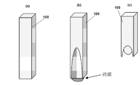
抵抗加熱ヒータを用いた装置で、種結晶を融液に着液して引上げることによりサファイア単結晶をCZ法によって製造する際、図3(a)のような形状の種結晶100を融液に着液させる前に、図3(b)のように側面が溶けて、その後、図3(c)のように種結晶100の下部が溶け落ちてしまうという問題が発生した。
このような問題に対して、本発明者らは以下のような検討を行った。
このような問題に対して、本発明者らは以下のような検討を行った。
半透明材料に対する輻射伝熱量は、表面での反射と材料を透過する分を除いた量として計算される。図4に波長域によるサファイアの透過率を示す。図5にサファイアの吸収係数の温度依存性を示す。
図4に示すように、室温において、サファイアは、0.5μmから5μmの波長域で85%程度の透過率を有する。また、図5に示すように、温度が上がると吸収しやすくはなるが、それでも吸収熱量はごく僅かである。しかし、バンドソーやワイヤーソーから切り出された種結晶の場合、その表面が粗いために赤外線が透過しにくく、表層温度が高くなってしまい溶損に至るものと考えられる。本発明者らは、この問題を解決するため、切削された種結晶に、例えばダイヤモンド砥粒を用いた研磨処理を施すことで、種結晶の表面での赤外線吸収を抑制して、溶損を防止できることを見出して、本発明を完成させた。
図4に示すように、室温において、サファイアは、0.5μmから5μmの波長域で85%程度の透過率を有する。また、図5に示すように、温度が上がると吸収しやすくはなるが、それでも吸収熱量はごく僅かである。しかし、バンドソーやワイヤーソーから切り出された種結晶の場合、その表面が粗いために赤外線が透過しにくく、表層温度が高くなってしまい溶損に至るものと考えられる。本発明者らは、この問題を解決するため、切削された種結晶に、例えばダイヤモンド砥粒を用いた研磨処理を施すことで、種結晶の表面での赤外線吸収を抑制して、溶損を防止できることを見出して、本発明を完成させた。
以下、本発明について、実施態様の一例として、図を参照しながら詳細に説明するが、本発明はこれに限定されるものではない。
図1は、本発明の種結晶の一例を示す概略図である。
図1は、本発明の種結晶の一例を示す概略図である。
本発明は、CZ法により、タングステン又はモリブデン、あるいはタングステンとモリブデンの両方を主成分とするルツボ内で原料を抵抗加熱ヒータによって加熱溶融して得られた融液に、種結晶を着液させて引上げることによりサファイア単結晶を製造する方法である。
そして、本発明では、融液に着液させる種結晶として、研磨加工が施された種結晶を用いる。
そして、本発明では、融液に着液させる種結晶として、研磨加工が施された種結晶を用いる。
このように種結晶を研磨して透明化することで、抵抗加熱ヒータからの赤外線の透過率をサファイア本来の透過率に近づけて高くすることができる。このような種結晶を用いることで、種付けの着液前に側面等が溶け落ちることを効果的に防止することができ、サファイア単結晶の生産性を向上させることができる。
本発明の種結晶としては、サファイア単結晶から、図1に示すような直方体の単結晶をバンドソーやワイヤーソーにより切り出して、その表面を例えばダイヤモンド砥粒を用いた研磨装置で研磨して、種結晶10とする。なお、種結晶の形状としては、これに限定されず、円柱形状等のものを用いることもできる。
このとき、側面に研磨加工が施された種結晶10を用いることが好ましい。
側面は、抵抗加熱ヒータからの熱を受けやすく、また、側面が溶けると着液させる底面とともに種結晶の下部が溶け落ちてしまうため、例えば側面のみを研磨することで、効率的に種結晶の溶損を防止することができる。
側面は、抵抗加熱ヒータからの熱を受けやすく、また、側面が溶けると着液させる底面とともに種結晶の下部が溶け落ちてしまうため、例えば側面のみを研磨することで、効率的に種結晶の溶損を防止することができる。
また、さらに全面に研磨加工が施された種結晶10を用いることが好ましい。
上記のように全面を研磨することで、種結晶の赤外線透過率をより高くすることができ、溶損をより効果的に防止することができる。
上記のように全面を研磨することで、種結晶の赤外線透過率をより高くすることができ、溶損をより効果的に防止することができる。
このとき、研磨加工が施されて表面粗さRa値を100nm以下、特には10nm以下とした種結晶を用いることが好ましい。
このような表面粗さであれば、赤外線の透過率が十分に高く、種結晶が抵抗加熱ヒータからの熱で溶けることをより効果的に防止できる。
このような表面粗さであれば、赤外線の透過率が十分に高く、種結晶が抵抗加熱ヒータからの熱で溶けることをより効果的に防止できる。
上記のような本発明の種結晶を用いてサファイア単結晶を引上げる際には、例えば図2に示すような単結晶製造装置を用いることができる。
図2の単結晶製造装置23は、CZ法により、ルツボ14内でアルミナ原料を加熱溶融して得られた融液15からサファイア単結晶17を引上げて製造する装置である。ルツボ14は、タングステン又はモリブデン、あるいはタングステンとモリブデンの両方を主成分とするものである。これらは、イリジウムより安価で、コスト低減に有利である。
単結晶製造装置23は、メインチャンバー11内にルツボ14と、ルツボ14を囲繞し、ルツボ14内の原料を加熱する抵抗加熱ヒータ22とを備えたものである。さらに、メインチャンバー11上にゲートバルブ12で仕切り可能に接続されたプルチャンバー13を備えることもできる。このようなプルチャンバー13を有することで、抵抗加熱ヒータ22の電源を落とすことなく原料のチャージを行うことができる。
単結晶製造装置23は、メインチャンバー11内にルツボ14と、ルツボ14を囲繞し、ルツボ14内の原料を加熱する抵抗加熱ヒータ22とを備えたものである。さらに、メインチャンバー11上にゲートバルブ12で仕切り可能に接続されたプルチャンバー13を備えることもできる。このようなプルチャンバー13を有することで、抵抗加熱ヒータ22の電源を落とすことなく原料のチャージを行うことができる。
図2に示すように、この単結晶製造装置23は、ガス導入管25とガス排出管26を有し、例えば、単結晶成長時等の操業時はプルチャンバー13の上方から不活性ガス等を炉内にガス導入管25を介して導入し、この導入したガスを、メインチャンバー11の底部のガス排出管26から真空ポンプ24等により炉外へ排出することができる。一方、原料チャージ等の際には、ゲートバルブ12を閉めてプルチャンバー13内で作業を行い、その後、プルチャンバー13内をプルチャンバー用のガス排出管27とガス導入管25を用いてガス置換して、プルチャンバー13をメインチャンバー11と同じ条件にしてからゲートバルブ12を開くことで、引き続いて単結晶育成工程を行うことができる。
また、単結晶製造装置23は、ルツボ14や抵抗加熱ヒータ22を囲む黒鉛系フェルト材等の断熱材16と、サファイア単結晶17の引上げに用いる引上げ軸20と、種結晶10を保持する種ホルダー21と、ルツボ14を支えるモリブデン等の金属製保持具18と、ルツボ14をモリブデン等の金属製保持具18を介して支持する例えばモリブデン製のルツボ支持軸19とを備える。
上記のような単結晶製造装置23を用いて、本発明の種結晶10を融液15に着液させて引上げることで、サファイア単結晶17を育成することができる。本発明であれば、たとえ抵抗加熱ヒータ22を用いた温度分布が均一になり易い炉内構造であっても、種付けの際の種結晶10の溶損を効果的に防止できるため、サファイア単結晶の歩留まりを向上することができる。
以下、実施例及び比較例を示して本発明をより具体的に説明するが、本発明はこれらに限定されるものではない。
(実施例、比較例)
図2の装置を用いて、等方性黒鉛ならびに、炭素繊維を成型した断熱材を用いた炉内に、15kgの高純度アルミナを入れたモリブデンルツボをセットし、抵抗加熱ヒータで加熱して溶融した。その後、10mm角×100mm長さの直方体のc軸種結晶をゆっくりと降ろしていき、着液させて種付けを行った。
(実施例、比較例)
図2の装置を用いて、等方性黒鉛ならびに、炭素繊維を成型した断熱材を用いた炉内に、15kgの高純度アルミナを入れたモリブデンルツボをセットし、抵抗加熱ヒータで加熱して溶融した。その後、10mm角×100mm長さの直方体のc軸種結晶をゆっくりと降ろしていき、着液させて種付けを行った。
種結晶としては、切削面をそのまま有するもの(比較例)、及び、切削面に、ダイヤモンド砥粒を用いた研磨を施した研磨面を有するもの(実施例)を2種類用い、また、融液温度を3水準で変えて種結晶の溶損状況を比較した。結果を表1に示す。
また、上記研磨した研磨面の表面粗さは、Ra値で10nm程度であった。なお、表1における融液の最適温度とは、種付け後にメニスカスが形成され、なおかつ、その後、半径方向に結晶成長しない状態となる融液温度を意味する。

表1に示すように、研磨を施した種結晶は、いずれの温度でも種結晶の下部が溶け落ちる溶損は生じなかった。温度が最適温度+5℃の場合には、わずかに側面が溶けたが、種付けは実施可能であった。一方、研磨を施さなかった種結晶は、種結晶の下部が溶け落ちて溶損が生じた。
なお、本発明は、上記実施形態に限定されるものではない。上記実施形態は、例示であり、本発明の特許請求の範囲に記載された技術的思想と実質的に同一な構成を有し、同様な作用効果を奏するものは、いかなるものであっても本発明の技術的範囲に包含される。
Claims (6)
- CZ法により、タングステン又はモリブデン、あるいはタングステンとモリブデンの両方を主成分とするルツボ内で原料を抵抗加熱ヒータによって加熱溶融して得られた融液に、種結晶を着液させて引上げることによりサファイア単結晶を製造する方法であって、
前記融液に着液させる種結晶として、研磨加工が施された種結晶を用いることを特徴とするサファイア単結晶の製造方法。 - 前記融液に着液させる種結晶として、側面に研磨加工が施された種結晶を用いることを特徴とする請求項1に記載のサファイア単結晶の製造方法。
- 前記融液に着液させる種結晶として、全面に研磨加工が施された種結晶を用いることを特徴とする請求項1に記載のサファイア単結晶の製造方法。
- 前記融液に着液させる種結晶として、研磨加工が施されて表面粗さRa値を100nm以下とした種結晶を用いることを特徴とする請求項1乃至請求項3のいずれか一項に記載のサファイア単結晶の製造方法。
- CZ法によりサファイア単結晶を製造する際に用いられる種結晶であって、該種結晶は、研磨加工が施されたものであることを特徴とする種結晶。
- 前記種結晶の研磨加工が施された面は、表面粗さRa値が100nm以下であることを特徴とする請求項5に記載の種結晶。
Applications Claiming Priority (2)
| Application Number | Priority Date | Filing Date | Title |
|---|---|---|---|
| JP2012-246100 | 2012-11-08 | ||
| JP2012246100A JP5915506B2 (ja) | 2012-11-08 | 2012-11-08 | サファイア単結晶の製造方法及び種結晶 |
Publications (1)
| Publication Number | Publication Date |
|---|---|
| WO2014073147A1 true WO2014073147A1 (ja) | 2014-05-15 |
Family
ID=50684276
Family Applications (1)
| Application Number | Title | Priority Date | Filing Date |
|---|---|---|---|
| PCT/JP2013/005830 Ceased WO2014073147A1 (ja) | 2012-11-08 | 2013-10-01 | サファイア単結晶の製造方法及び種結晶 |
Country Status (3)
| Country | Link |
|---|---|
| JP (1) | JP5915506B2 (ja) |
| TW (1) | TW201425662A (ja) |
| WO (1) | WO2014073147A1 (ja) |
Citations (4)
| Publication number | Priority date | Publication date | Assignee | Title |
|---|---|---|---|---|
| JPH08104595A (ja) * | 1994-09-30 | 1996-04-23 | Hitachi Chem Co Ltd | 単結晶の育成方法 |
| JP2009280411A (ja) * | 2008-05-19 | 2009-12-03 | Tokuyama Corp | フッ化金属単結晶体製造用の種結晶体 |
| JP2012020923A (ja) * | 2010-06-17 | 2012-02-02 | Sumco Corp | サファイアシードおよびその製造方法、ならびにサファイア単結晶の製造方法 |
| JP2012193061A (ja) * | 2011-03-15 | 2012-10-11 | Sumco Corp | シード軸とシードホルダとの連結構造 |
-
2012
- 2012-11-08 JP JP2012246100A patent/JP5915506B2/ja not_active Expired - Fee Related
-
2013
- 2013-10-01 WO PCT/JP2013/005830 patent/WO2014073147A1/ja not_active Ceased
- 2013-10-11 TW TW102136788A patent/TW201425662A/zh unknown
Patent Citations (4)
| Publication number | Priority date | Publication date | Assignee | Title |
|---|---|---|---|---|
| JPH08104595A (ja) * | 1994-09-30 | 1996-04-23 | Hitachi Chem Co Ltd | 単結晶の育成方法 |
| JP2009280411A (ja) * | 2008-05-19 | 2009-12-03 | Tokuyama Corp | フッ化金属単結晶体製造用の種結晶体 |
| JP2012020923A (ja) * | 2010-06-17 | 2012-02-02 | Sumco Corp | サファイアシードおよびその製造方法、ならびにサファイア単結晶の製造方法 |
| JP2012193061A (ja) * | 2011-03-15 | 2012-10-11 | Sumco Corp | シード軸とシードホルダとの連結構造 |
Also Published As
| Publication number | Publication date |
|---|---|
| JP2014094847A (ja) | 2014-05-22 |
| JP5915506B2 (ja) | 2016-05-11 |
| TW201425662A (zh) | 2014-07-01 |
Similar Documents
| Publication | Publication Date | Title |
|---|---|---|
| CN104372408B (zh) | 常压下提拉法生长大尺寸氧化镓单晶的方法 | |
| JP5839117B2 (ja) | SiC単結晶及びその製造方法 | |
| WO2011001905A1 (ja) | サファイア単結晶の製造方法、及び当該方法で得られたサファイア単結晶 | |
| CN102586866A (zh) | 在采用导模法生长片状蓝宝石过程中抑制气泡的方法 | |
| CN102758249A (zh) | 一种无色刚玉单晶的制备方法 | |
| CN105229208A (zh) | β-Ga2O3系单晶的培育方法以及β-Ga2O3系单晶基板及其制造方法 | |
| CN104066874A (zh) | 单晶制造装置所使用的籽晶保持轴以及单晶制造方法 | |
| JP2012131679A (ja) | 炭化珪素単結晶インゴットの製造装置 | |
| JP2014221707A (ja) | β−Ga2O3系単結晶の育成方法、並びにβ−Ga2O3系単結晶基板及びその製造方法 | |
| TWI580827B (zh) | Sapphire single crystal nucleus and its manufacturing method | |
| JP5318365B2 (ja) | シリコン結晶素材及びこれを用いたfzシリコン単結晶の製造方法 | |
| JP4473769B2 (ja) | 炭化珪素単結晶の焼鈍方法 | |
| JP2015182944A (ja) | サファイア単結晶の製造方法 | |
| JP5761264B2 (ja) | SiC基板の製造方法 | |
| JP5915506B2 (ja) | サファイア単結晶の製造方法及び種結晶 | |
| CN104499049B (zh) | 一种铸锭过程中去除多晶硅硬质夹杂的方法 | |
| WO2023230243A1 (en) | Enclosed crystal growth | |
| JP5949601B2 (ja) | 多層型熱反射板およびこれを用いた酸化物単結晶育成装置 | |
| JP2014224041A (ja) | β−Ga2O3系単結晶基板 | |
| KR101293706B1 (ko) | 사파이어 단결정의 제조장치 | |
| JP2010265150A (ja) | サファイア単結晶の製造方法及び種結晶の製造方法 | |
| WO2013125161A1 (ja) | 単結晶製造装置及び単結晶製造方法 | |
| JP2006342029A (ja) | フッ化金属単結晶を熱処理するために用いるアニール炉及びフッ化金属単結晶のアニール方法 | |
| JP2014162698A (ja) | サファイア単結晶の製造方法 | |
| JP2014162668A (ja) | 単結晶製造装置 |
Legal Events
| Date | Code | Title | Description |
|---|---|---|---|
| 121 | Ep: the epo has been informed by wipo that ep was designated in this application |
Ref document number: 13853518 Country of ref document: EP Kind code of ref document: A1 |
|
| NENP | Non-entry into the national phase |
Ref country code: DE |
|
| 122 | Ep: pct application non-entry in european phase |
Ref document number: 13853518 Country of ref document: EP Kind code of ref document: A1 |