WO2014073142A1 - 電磁クラッチ、電磁クラッチの制御装置及び電磁クラッチの制御方法 - Google Patents
電磁クラッチ、電磁クラッチの制御装置及び電磁クラッチの制御方法 Download PDFInfo
- Publication number
- WO2014073142A1 WO2014073142A1 PCT/JP2013/005669 JP2013005669W WO2014073142A1 WO 2014073142 A1 WO2014073142 A1 WO 2014073142A1 JP 2013005669 W JP2013005669 W JP 2013005669W WO 2014073142 A1 WO2014073142 A1 WO 2014073142A1
- Authority
- WO
- WIPO (PCT)
- Prior art keywords
- rotor
- armature
- electromagnetic coil
- electromagnetic clutch
- electromagnetic
- Prior art date
- Legal status (The legal status is an assumption and is not a legal conclusion. Google has not performed a legal analysis and makes no representation as to the accuracy of the status listed.)
- Ceased
Links
Images






Classifications
-
- F—MECHANICAL ENGINEERING; LIGHTING; HEATING; WEAPONS; BLASTING
- F16—ENGINEERING ELEMENTS AND UNITS; GENERAL MEASURES FOR PRODUCING AND MAINTAINING EFFECTIVE FUNCTIONING OF MACHINES OR INSTALLATIONS; THERMAL INSULATION IN GENERAL
- F16D—COUPLINGS FOR TRANSMITTING ROTATION; CLUTCHES; BRAKES
- F16D48/00—External control of clutches
- F16D48/06—Control by electric or electronic means, e.g. of fluid pressure
- F16D48/064—Control of electrically or electromagnetically actuated clutches
-
- F—MECHANICAL ENGINEERING; LIGHTING; HEATING; WEAPONS; BLASTING
- F16—ENGINEERING ELEMENTS AND UNITS; GENERAL MEASURES FOR PRODUCING AND MAINTAINING EFFECTIVE FUNCTIONING OF MACHINES OR INSTALLATIONS; THERMAL INSULATION IN GENERAL
- F16D—COUPLINGS FOR TRANSMITTING ROTATION; CLUTCHES; BRAKES
- F16D27/00—Magnetically- or electrically- actuated clutches; Control or electric circuits therefor
- F16D27/10—Magnetically- or electrically- actuated clutches; Control or electric circuits therefor with an electromagnet not rotating with a clutching member, i.e. without collecting rings
- F16D27/108—Magnetically- or electrically- actuated clutches; Control or electric circuits therefor with an electromagnet not rotating with a clutching member, i.e. without collecting rings with axially movable clutching members
- F16D27/112—Magnetically- or electrically- actuated clutches; Control or electric circuits therefor with an electromagnet not rotating with a clutching member, i.e. without collecting rings with axially movable clutching members with flat friction surfaces, e.g. discs
-
- F—MECHANICAL ENGINEERING; LIGHTING; HEATING; WEAPONS; BLASTING
- F16—ENGINEERING ELEMENTS AND UNITS; GENERAL MEASURES FOR PRODUCING AND MAINTAINING EFFECTIVE FUNCTIONING OF MACHINES OR INSTALLATIONS; THERMAL INSULATION IN GENERAL
- F16D—COUPLINGS FOR TRANSMITTING ROTATION; CLUTCHES; BRAKES
- F16D2500/00—External control of clutches by electric or electronic means
- F16D2500/10—System to be controlled
- F16D2500/102—Actuator
- F16D2500/1021—Electrical type
- F16D2500/1022—Electromagnet
-
- F—MECHANICAL ENGINEERING; LIGHTING; HEATING; WEAPONS; BLASTING
- F16—ENGINEERING ELEMENTS AND UNITS; GENERAL MEASURES FOR PRODUCING AND MAINTAINING EFFECTIVE FUNCTIONING OF MACHINES OR INSTALLATIONS; THERMAL INSULATION IN GENERAL
- F16D—COUPLINGS FOR TRANSMITTING ROTATION; CLUTCHES; BRAKES
- F16D2500/00—External control of clutches by electric or electronic means
- F16D2500/50—Problem to be solved by the control system
- F16D2500/51—Relating safety
- F16D2500/5108—Failure diagnosis
-
- F—MECHANICAL ENGINEERING; LIGHTING; HEATING; WEAPONS; BLASTING
- F16—ENGINEERING ELEMENTS AND UNITS; GENERAL MEASURES FOR PRODUCING AND MAINTAINING EFFECTIVE FUNCTIONING OF MACHINES OR INSTALLATIONS; THERMAL INSULATION IN GENERAL
- F16D—COUPLINGS FOR TRANSMITTING ROTATION; CLUTCHES; BRAKES
- F16D2500/00—External control of clutches by electric or electronic means
- F16D2500/50—Problem to be solved by the control system
- F16D2500/51—Relating safety
- F16D2500/5114—Failsafe
-
- F—MECHANICAL ENGINEERING; LIGHTING; HEATING; WEAPONS; BLASTING
- F16—ENGINEERING ELEMENTS AND UNITS; GENERAL MEASURES FOR PRODUCING AND MAINTAINING EFFECTIVE FUNCTIONING OF MACHINES OR INSTALLATIONS; THERMAL INSULATION IN GENERAL
- F16D—COUPLINGS FOR TRANSMITTING ROTATION; CLUTCHES; BRAKES
- F16D2500/00—External control of clutches by electric or electronic means
- F16D2500/70—Details about the implementation of the control system
- F16D2500/704—Output parameters from the control unit; Target parameters to be controlled
- F16D2500/70402—Actuator parameters
- F16D2500/70418—Current
-
- F—MECHANICAL ENGINEERING; LIGHTING; HEATING; WEAPONS; BLASTING
- F16—ENGINEERING ELEMENTS AND UNITS; GENERAL MEASURES FOR PRODUCING AND MAINTAINING EFFECTIVE FUNCTIONING OF MACHINES OR INSTALLATIONS; THERMAL INSULATION IN GENERAL
- F16D—COUPLINGS FOR TRANSMITTING ROTATION; CLUTCHES; BRAKES
- F16D2500/00—External control of clutches by electric or electronic means
- F16D2500/70—Details about the implementation of the control system
- F16D2500/704—Output parameters from the control unit; Target parameters to be controlled
- F16D2500/70402—Actuator parameters
- F16D2500/7042—Voltage
-
- F—MECHANICAL ENGINEERING; LIGHTING; HEATING; WEAPONS; BLASTING
- F16—ENGINEERING ELEMENTS AND UNITS; GENERAL MEASURES FOR PRODUCING AND MAINTAINING EFFECTIVE FUNCTIONING OF MACHINES OR INSTALLATIONS; THERMAL INSULATION IN GENERAL
- F16D—COUPLINGS FOR TRANSMITTING ROTATION; CLUTCHES; BRAKES
- F16D2500/00—External control of clutches by electric or electronic means
- F16D2500/70—Details about the implementation of the control system
- F16D2500/71—Actions
- F16D2500/7107—Others
- F16D2500/7109—Pulsed signal; Generating or processing pulsed signals; PWM, width modulation, frequency or amplitude modulation
Definitions
- the present disclosure relates to an electromagnetic clutch that performs intermittent transmission of power using an electromagnet, an electromagnetic clutch control device, and an electromagnetic clutch control method.
- Electromagnetic clutches are used when power transmission is interrupted using electromagnetic coils in the drive mechanism of a compressor for a vehicle air conditioner.
- An armature is fixed to the tip of the rotating shaft of the compressor, and a rotor driven by an engine or the like is attached to the rotating shaft adjacent to the armature via a bearing so that it can rotate with respect to the rotating shaft. It has become.
- a recess is formed in the rotor in a ring shape from the compressor side, and a stator including an electromagnetic coil is inserted into the recess with a gap between the recess and the inner wall. The armature can move to the rotor side.
- the armature When the electromagnetic coil is energized, the armature is attracted to the rotor side and fixed to the rotor by the magnetic flux passing between the rotor and the armature. A friction plate is provided on the contact surface of the rotor with the armature. When the armature is fixed to the rotor, the rotation of the rotor is transmitted to the rotation shaft of the compressor via the armature, and the compressor rotates.
- an armature is separated into an inner armature and an outer armature by a slit that circulates in the circumferential direction, and the inner armature and the outer armature are connected by a connecting portion (bridge) that divides the slit into a plurality of portions in the circumferential direction.
- the rotor that is magnetically coupled to the armature is provided with two slits in the circumferential direction so as not to overlap the armature slit, and the rotor is divided into the outer rotor, the central rotor, and the inner rotor by the two slits.
- the outer rotor and the central rotor, and the central rotor and the inner rotor are connected by a connecting portion that divides the slit into a plurality of portions in the circumferential direction.
- a connecting portion that divides the slit into a plurality of portions in the circumferential direction.
- the magnetic flux is blocked by the slit, so that the magnetic flux enters the inner armature from the inner rotor through the first facing surface. . Since the magnetic flux entering the inner armature is also blocked by the slit, it enters the central rotor through the second opposing surface, then enters the outer armature through the third opposing surface, and returns to the outer rotor through the fourth opposing surface.
- the magnetic flux penetrates between the rotor and the armature in a path (magnetic path) of the inner rotor ⁇ inner armature ⁇ center rotor ⁇ outer armature ⁇ outer rotor so that the attractive force between the rotor and the armature becomes strong.
- the armature is provided with two slits in the circumferential direction
- the rotor is provided with three slits in the circumferential direction so as not to overlap the slits of the armature, so that the opposing surface between the armature and the rotor is 6
- An electromagnetic clutch as a location has also been proposed (see, for example, Patent Document 1).
- An electromagnetic clutch having six opposing surfaces between the armature and the rotor requires only about 2/3 of the magnetic flux to obtain the same transmission torque when the electromagnetic coil is energized, compared to an electromagnetic clutch having four opposing surfaces.
- There is a feature and power consumption can be kept low.
- the thickness of the iron part which comprises the magnetic circuit of an electromagnetic coil can also be made thin, the electromagnetic clutch can be reduced in weight, and the fuel consumption performance of a vehicle improves.
- the facing surface on which the magnetic path is formed is called an attracting surface or a magnetic pole.
- the facing surface has four electromagnetic clutches with double flux and the facing surface has six electromagnetic surfaces.
- the clutch is called a triple flux electromagnetic clutch. In the present application, hereinafter, a description will be given by assuming that a portion (opposing surface) where the magnetic flux crosses the air gap between the rotor and the armature is an opposing magnetic path.
- the electromagnetic clutch can generate a higher transmission torque when the counter magnetic path between the rotor and the armature is provided at six places than when the counter magnetic path is provided at four places.
- the magnetic path across the air gap between the rotor and the armature becomes longer.
- the electromagnetic attractive force at the start of energization of the electromagnetic coil that is, the operating attractive force for switching the electromagnetic clutch from the OFF state to the ON state is small, and the operability (starting characteristics) of the electromagnetic clutch may be deteriorated. It was.
- the present disclosure provides an electromagnetic clutch, an electromagnetic clutch control device, and an electromagnetic clutch control method that improve the starting characteristics of the electromagnetic clutch and improve the operability of the electromagnetic clutch while suppressing the power consumption of the electromagnetic clutch. It is to provide.
- the armature attached to the rotating shaft, at least two non-magnetic portions provided in the armature and having different radii in the circumferential direction, and the rotating shaft by the external force
- An electromagnetic clutch control device includes an armature attached to a rotating shaft, at least two non-magnetic portions having different radii in the circumferential direction, and the rotation by an external force.
- a rotor that rotates with respect to the shaft, a friction plate that is provided on the rotor so as to face the armature, and a friction plate that is provided on the friction plate so as not to overlap the non-magnetic portion with different circumferential radii.
- a control device for an electromagnetic clutch wherein when an energization start command is issued to the electromagnetic coil, the magnetomotive force of the electromagnetic coil is increased, and the armature is electromagnetically attracted before When fixed to the rotor, it comprises a magnetomotive force change unit that returns the magnetomotive force magnetomotive force in the normal operation of the electromagnetic coil.
- the armature attached to the rotation shaft, the armature provided with at least two non-magnetic portions having different radii in the circumferential direction, and the rotation by the external force.
- a stator an electromagnetic coil that is provided in the stator, applies magnetic flux generated by energization to the friction plate, and electromagnetically attracts the armature to be fixed to the rotor, and the electromagnetic coil
- a control device that controls the energization of the electromagnetic clutch, wherein when the energization start command is issued to the electromagnetic coil, the electromagnetic coil is supplied to the control device.
- the armature when being electromagnetic attraction fixed to the rotor, to perform the operation of returning to the magnetomotive force in the normal operation of the magnetomotive force of the electromagnetic coil to the controller.
- FIG. 1B is a configuration diagram of an example of an electromagnetic clutch including a cross-sectional configuration of the electromagnetic clutch according to the first embodiment of the present disclosure attached to the compressor of the car air conditioner system illustrated in FIG. 1A.
- FIG. 2 is a partial configuration diagram showing a configuration of a modified embodiment of the embodiment described with reference to FIG. 2A, in which a PWM control circuit is used instead of a DC-DC converter.
- (B) is a schematic cross-sectional view showing the state of the armature and rotor in the case (on), and (b) is the armature in the case where the gap between the opposed magnetic paths of the electromagnetic clutch shown in (a) is 0.5 mm (off).
- Schematic cross-sectional view showing the state of the rotor (c) is an armature having two ring-shaped non-magnetic portions on the armature and three clutch-shaped non-magnetic portions on the friction plate of the rotor between the opposing magnetic paths.
- FIG. 2B is a waveform diagram for explaining an example of the operation of the DC-DC converter shown in FIG. 2A.
- FIG. 2B It is a wave form diagram explaining an example of operation
- FIG. 9B is a partial configuration diagram showing an embodiment in which a PWM control circuit is used instead of a DC-DC converter, showing a configuration of a modified embodiment of the embodiment described in FIG. 9A. It is the front view and sectional drawing of a rotor and an armature which show a slit arrangement and a connecting part position of a rotor provided with four slits, and an armature provided with three slits.
- FIG. 1A shows an example of the configuration of a car air conditioner system 80 when the electromagnetic clutch 100 of the present disclosure is installed in a compressor (compressor) 71 of an air conditioner (car air conditioner) 70 for an automobile.
- the car air conditioner 70 cools and dehumidifies the air in the passenger compartment to keep it comfortable, and includes a compressor 71, a condenser 72, a storage 73, an expansion valve 74, an evaporator 75, and a refrigerant passage 76 connecting them. Yes.
- the refrigerant sealed in the refrigerant passage 76 is compressed by the compressor 71 to be a high temperature / high pressure gas, cooled by the condenser 72 and liquefied, and then temporarily stored in the storage 73.
- the refrigerant coming out of the storage 73 becomes a low-pressure / low-temperature mist in the expansion valve 74, vaporized in the evaporator 75, takes heat from the surroundings, becomes a complete gaseous refrigerant, and returns to the compressor 71.
- the air in the vehicle interior or the outside air is cooled by passing through the evaporator 75, and the temperature in the vehicle interior is adjusted by blowing the air into the vehicle interior by adjusting the temperature through a heater core provided separately.
- the compressor 71 is driven by the engine 60, and the belt 62 is stretched between the pulley 61 attached to the rotating shaft 67 of the engine 60 and the pulley 14 attached to the rotating shaft 7 of the compressor 71. Driven by.
- the electromagnetic clutch 100 transmits or blocks the rotation of the pulley 14 to the rotating shaft 7 of the compressor 71.
- the electromagnetic clutch 100 transmits the driving force of the engine 60 to the compressor 71 when the electromagnetic coil 3 is energized and shuts off the driving force of the engine 60 when the electromagnetic coil 3 is not energized.
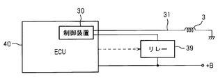
- the electromagnetic coil 3 is connected to the vehicle-mounted battery 38 through the control device 30 and the relay 39.
- the relay 39 When the relay 39 is turned on and the current value (magnetomotive force of the electromagnetic coil) is determined by the control device 30, the current from the battery 38 is It flows through the electromagnetic coil 3.
- the controller 30 is provided with a magnetomotive force changing circuit (magnetomotive force changing unit) 10, and the magnetomotive force applied to the electromagnetic coil 3 can be changed by the magnetomotive force changing circuit 10.
- the relay 39 can be turned on / off and the magnetomotive force can be changed by the magnetomotive force changing circuit 10 by an air conditioner computer (ECU) 40 that issues a command indicated by a broken line to the relay 39 and the control device 30.
- ECU air conditioner computer
- the vehicle-side ECU need not be changed.
- the control device 30 can also be built in the ECU 40 as in the modified embodiment shown in FIG. 1B.
- + B indicates a + terminal (battery power supply) of the battery 38 shown in FIG. 1A.
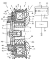
- FIG. 2A shows a configuration of an example of the electromagnetic clutch 100 including a cross-sectional configuration of the electromagnetic clutch 100 of the first embodiment of the present disclosure attached to the compressor 71 of the car air conditioner system 80 shown in FIG. 1A.
- the rotor 1 composed mostly of a magnetic material such as iron is fixed to a housing 77 of a compressor 71 through a bearing 6 so as to be freely rotatable.
- 79B is a retaining ring that fixes the bearing 6 to the housing 77 of the compressor 71.
- the inner hub 5 is fixed to the front end portion of the rotating shaft 7 of the compressor 71 by a bolt 15.
- An outer hub 17 is attached to the outer peripheral portion of the inner hub 5 via a damper rubber 16.
- the armature 4 which is mostly made of a magnetic material, is fixed to the surface of the outer hub 17 on the rotor 1 side by a mounting member 19.
- the inner hub 5, the damper rubber 16, the outer hub 17 and the armature 4 rotate together with the rotating shaft 7. At this time, the armature 4 is elastically held by the action of the damper rubber 16 with respect to the inner hub 5 and can move to the rotor 1 side.
- the end plate on the armature 4 side is a friction plate 8, and the friction surface on the surface of the friction plate 8 is connected to and cut off from the armature 4.
- the outer peripheral part of the rotor 1 becomes the pulley 14 shown to FIG. 1A, and the V protrusion of the belt which is not shown in figure engages with the several V groove provided in the pulley 14.
- the rotor 1 is formed with a ring-shaped recess 18 that opens to the housing 77 side of the compressor 71, and the rotor 1 has a U-shaped cross section.
- the stator 2 fixed to the housing 77 of the compressor 71 is inserted into the recess 18.
- the stator 2 includes an electromagnetic coil 3 wound in a ring-shaped spool 21, a yoke portion 22 provided around the spool 21, and a mounting plate 78 to which the yoke portion 22 is fixed.
- the mounting plate 78 is fixed to the housing 77 of the compressor 71 by a retaining ring 79A.
- the spool 21 is formed by resin molding using an electrically insulating resin as a constituent material.
- the yoke portion 22 of the stator 2 has a through hole 22a, and both end portions of the electromagnetic coil 3 are drawn out by lead wires 31 through the through hole 22a.
- a DC-DC converter (voltage changing unit) 11 that boosts the voltage of the battery power source + B is built in the controller 30 as a magnetomotive force changing circuit 10.
- a PWM control circuit (duty ratio changing unit) 12 shown in FIG. 2B can be used instead of the DC-DC converter 11.
- the friction plate 8 on the armature 4 side of the rotor 1 of the present disclosure is provided with three or more ring-shaped slits having different radii as nonmagnetic portions that are magnetic shielding portions. This slit links the magnetic flux generated by the electromagnetic coil 3 built in the stator 2 to the armature 4 side.
- the friction plate 8 of this embodiment is provided with three ring-shaped slits 81, 82, 83 having different radii in order from the bearing 6 side.
- the friction plate 8 is divided into the first rotor portion 8A, the second rotor portion 8B, the third rotor portion 8C, and the fourth rotor portion 8D from the rotary shaft 7 side by the slits 81, 82, 83.
- the first rotor portion 8A and the second rotor portion 8B, the second rotor portion 8B and the third rotor portion 8C, and the third rotor portion 8C and the fourth rotor portion 8D. are connected to the slits 81, 82, 83.
- This connecting portion will be described later.
- the non-magnetic ring is formed by filling the gaps of the slits 81, 82, and 83 with a non-magnetic material such as copper or stainless steel, a connecting portion is unnecessary.
- the armature 4 which is an annular plate-shaped member facing the friction plate 8, has two ring-shaped slits as nonmagnetic portions that are magnetic shielding portions in order to link the magnetic flux to the friction plate 8 side. Articles or more are provided.
- the radius of the slit provided in the armature 4 is different from the radius of the slit in the friction plate 8.
- the armature 4 of this embodiment is provided with two ring-shaped slits 41 and 42 having different radii in order from the rotating shaft 7 side.
- the armature 4 is divided into a first ring portion 4A, a second ring portion 4B, and a third ring portion 4C from the rotary shaft 7 side by the slits 41 and 42.
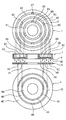
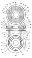
- FIG. 3 shows a schematic configuration of the rotor 1 provided with the three slits 81, 82, 83 used in the present disclosure and the armature 4 provided with the two slits 41, 42. 42, the relationship between the slits 81, 82, 83 and the connecting portion will be described.
- the connecting portions 85, 86, 87 are provided every 120 degrees with respect to the center of the rotor 1.
- the friction plate 8 is divided into the first rotor portion 8A, the second rotor portion 8B, the third rotor portion 8C, and the fourth rotor portion 8D from the inside by the slits 81, 82, 83.
- the opposing armature 4 is provided with the slits 41, 42 at the portions facing the second rotor portion 8B and the third rotor portion 8C, respectively. . Accordingly, the radii of the slits 41 and 42 are different from the radii of the slits 81, 82, and 83.
- the two slits 41 and 42 are provided in the armature 4, three connection portions 44 and 45 are provided in each of the slits 41 and 42.
- the connecting portions 44 and 45 are provided every 120 degrees with respect to the center of the armature 4. The number and position of the connecting portions 44 and 45 are not limited to this embodiment.
- the armature 4 is divided into a first ring portion 4A, a second ring portion 4B, and a third ring portion 4C from the inside by the slits 41 and 42.
- the first ring portion 4A faces the first rotor portion 8A and the second rotor portion 8B, and the second ring portion 4B becomes the second rotor portion 8B and the third rotor.
- the third ring portion 4C faces the third rotor portion 8C and the fourth rotor portion 8D.
- Six opposing magnetic paths are linked with each other along the route of the ring portion 4C ⁇ the fourth rotor portion 8D.
- a stronger attractive force is generated between the rotor 1 and the armature 4 than when there are only four locations.
- the magnetomotive force applied to the electromagnetic coil can be made smaller than when there are only four magnetic paths. This will be described with reference to FIGS.
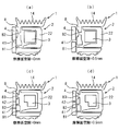
- FIG. 4A shows a friction surface gap (opposing) of an electromagnetic clutch in which the armature 4 has a single ring-shaped nonmagnetic portion 41 and the friction plate 8 of the rotor 1 has two ring-shaped nonmagnetic portions 81 and 82.
- FIG. 4B is a schematic cross-sectional view showing the state of the armature 4 and the rotor 1 when the gap between the opposed magnetic paths is 0.5 mm (when off) in the electromagnetic clutch shown in FIG.
- FIG. 4A shows a friction surface gap (opposing) of an electromagnetic clutch in which the armature 4 has a single ring-shaped nonmagnetic portion 41 and the friction plate 8 of the rotor 1 has two ring-shaped nonmagnetic portions 81 and 82.
- FIG. 4 (c) shows an opposing state of an electromagnetic clutch in which the armature 4 has two ring-shaped nonmagnetic portions 41, 42 and the friction plate 8 of the rotor 1 has three ring-shaped nonmagnetic portions 81, 82, 83.
- FIG. 4D is a schematic cross-sectional view showing the state of the armature 4 and the rotor 1 when the gap between the opposing magnetic paths is 0.5 mm (when off) in the electromagnetic clutch shown in FIG. 4 (a) to 4 (d) correspond to the members indicated by the reference numerals described in FIG.
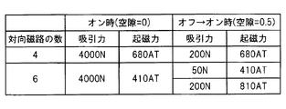
- FIG. 5 compares the number of opposing magnetic paths in the electromagnetic clutch shown in FIGS. 4 (a) to 4 (d) and the magnitude of the attractive force with respect to the magnetomotive force of the electromagnetic coil when on and off ⁇ on. It is a table to show.
- the magnetomotive force is an electric current for obtaining a necessary attractive force.
- the magnetomotive force for obtaining the attractive force 4000N at the on time is 680AT
- the magnetomotive force for obtaining the attractive force 200N at the off ⁇ on is 680AT. It is.
- the magnetomotive force for obtaining the attractive force 4000N at the time of ON may be 410AT. Therefore, the magnetomotive force when holding the electromagnetic clutch in the on state is smaller when the number of opposed magnetic paths is six.
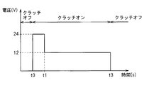
- FIG. 6A is a waveform diagram for explaining an embodiment of the operation of the DC-DC converter 11 shown in FIG. 2A.
- the DC-DC converter 11 raises the battery voltage of 12V to, for example, 24V and applies it to the electromagnetic coil.
- time t1 when the armature of the electromagnetic clutch is attracted by the rotor and the gap becomes zero, the DC-DC converter 11 returns the voltage applied to the electromagnetic coil to the battery voltage of 12V.
- the time t1 when the armature of the electromagnetic clutch is attracted by the rotor and the gap becomes 0 can be detected by providing a sensor in the electromagnetic clutch, but usually a predetermined elapsed time from the detection of the signal for turning on the electromagnetic clutch Can be determined as
- the time for which the armature of the electromagnetic clutch is attracted to the rotor and the gap becomes 0 varies depending on the model, but is between 0.1 and 1 second and may be determined according to the model.
- the power supply voltage is 12 V and a current of 2 A flows through the electromagnetic coil.
- FIG. 6B is a waveform diagram for explaining an embodiment of the operation of the PWM control circuit 12 shown in FIG. 2B.
- the PWM control circuit 12 when the electromagnetic clutch is turned on at time t0 when the electromagnetic clutch is in the off state, the duty ratio of the voltage applied to the electromagnetic coil is controlled by the PWM control circuit 12 to 100%. Then, at time t1 when the armature of the electromagnetic clutch is attracted by the rotor and the gap becomes zero, the duty ratio of the voltage applied to the electromagnetic coil is lowered by the PWM control circuit 12.
- the power supply voltage is 12 V and the duty ratio is 100%.
- the duty ratio is lowered so that a current of 2.3 A flows through the electromagnetic coil.
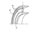
- FIG. 7A illustrates the structure of a ring-shaped slit
- FIG. 7B illustrates the structure of a nonmagnetic ring made of a nonmagnetic material such as copper or stainless steel, which is filled in the slit.
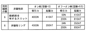
- FIGS. 7A and 7B show the case where the rotor is provided with two slits, but FIG. 8 shows the opposing magnet between the armature of the electromagnetic clutch and the rotor.
- the numerical value when the number of roads is 6 is shown. As shown in FIG.
- the connecting portions 85 and 86 are bridges made of the same material as the rotor 1 that divides the ring-shaped slits 81 and 82 that are nonmagnetic portions provided in the rotor 1 of the electromagnetic clutch.
- the nonmagnetic ring 89 is a ring made of a nonmagnetic material such as copper or stainless steel, which is filled in ring-shaped slits 81 and 82 provided in the rotor 1 of the electromagnetic clutch.
- the nonmagnetic ring 89 is a member that connects both sides of the ring-shaped slits 81 and 82. In the table shown in FIG.
- the number of opposed magnetic paths between the armature of the electromagnetic clutch and the rotor is 6, and when the nonmagnetic part is formed by a slit and when the nonmagnetic part is formed by a nonmagnetic ring, The magnitude of the attractive force with respect to the magnetomotive force of the electromagnetic coil at the time of off to on is shown.
- the slit is filled with a non-magnetic ring rather than the ring-shaped slit provided in the rotor is a gap.
- the magnetomotive force applied to the electromagnetic coil is small.
- the suction force is 50 N when the ring-shaped slit is a gap, and when the electromagnetic clutch is filled with a non-magnetic ring, The force is as small as 34N.
- the DC-DC converter 11 or the PWM control circuit 12 of the present disclosure shown in FIG. 2 is used for control, even if the number of opposed magnetic paths is 6, the ring-shaped slits provided in the rotor are not formed as gaps. It is possible to put to practical use an electromagnetic clutch filled with a non-magnetic ring. Note that the electromagnetic clutch 100 including the DC-DC converter 11 or the PWM control circuit 12 of the present disclosure shown in FIG. 2 can be controlled even when the number of opposed magnetic paths is more than six.
- FIG. 9A is a configuration diagram of an example of the electromagnetic clutch 100A including a cross-sectional configuration of the electromagnetic clutch 100A according to the second embodiment of the present disclosure attached to the compressor of the car air conditioner system illustrated in FIG. 1A.
- the electromagnetic clutch 100A of the second embodiment is different from the electromagnetic clutch 100 of the first embodiment only in the structure of the friction plate 8 and the armature 4 of the rotor 1, and the other structure is the electromagnetic clutch of the first embodiment. It is exactly the same as the clutch 100. Therefore, in the electromagnetic clutch 100A of the second embodiment, constituent members other than the friction plate 8 and the armature 4 are denoted by the same reference numerals as those of the electromagnetic clutch 100 of the first embodiment, and description thereof is omitted.
- the electromagnetic clutch 100 of the first embodiment in order to link the magnetic flux generated by the electromagnetic coil 3 built in the stator 2 to the friction plate 8 to the armature 4 side, the three strips having different radii in order from the bearing 6 side. Ring-shaped slits 81, 82, 83 were provided.
- the friction plate 8 is divided into the first rotor portion 8A, the second rotor portion 8B, the third rotor portion 8C, and the fourth rotor portion 8D from the rotary shaft 7 side by the slits 81, 82, 83.
- the friction plate 8 is provided with four ring-shaped slits 81, 82, 83, and 84 having different radii in order from the bearing 6 side. Then, the slits 81, 82, 83, 84 allow the friction plate 8 to move from the rotating shaft 7 side to the first rotor portion 8 A, the second rotor portion 8 B, the third rotor portion 8 C, the fourth rotor portion 8 D, and the fifth rotor portion. It is divided into 8E.
- connection portions are provided in the slits 81, 82, 83, 84 in order to connect the portion 8D, the fourth rotor portion 8D, and the fifth rotor portion 8E.
- a connecting portion is unnecessary.
- the armature 4 of the first embodiment was provided with two ring-shaped slits 41 and 42 having different radii in order from the rotating shaft 7 side.
- the armature 4 is divided into the first ring portion 4A, the second ring portion 4B, and the third ring portion 4C from the rotary shaft 7 side by the slits 41 and 42.
- the armature 4 is provided with three ring-shaped slits 41, 42, 43 having different radii in order from the rotary shaft 7 side.
- the armature 4 is divided into the first ring portion 4A, the second ring portion 4B, the third ring portion 4C, and the fourth ring portion 4D from the rotary shaft 7 side by the slits 41, 42, and 43.
- the slits 41, 42, 43 are left as gaps
- the non-magnetic ring is formed by filling the gaps of the slits 41, 42, and 43 with a non-magnetic member such as copper or stainless steel, a connecting portion is unnecessary.
- FIG. 9B shows a configuration of a modified example of one example of the electromagnetic clutch 100A of the second embodiment described in FIG. 9A, and the PWM control circuit 12 is used instead of the DC-DC converter 11. It is a partial block diagram which shows an Example. In the electromagnetic clutch 100A of the second embodiment, both the DC-DC converter 11 and the PWM control circuit 12 can be used.
- FIG. 10 shows a schematic configuration of the rotor 1 provided with the four slits 81, 82, 83, 84 and the armature 4 provided with the three slits 41, 42, 43 used in the present disclosure.
- FIG. 10 shows connection portions 44, 45, 46 in the slits 41, 42, 43 and connection portions 85, 86, 87, 88 in the slits 81, 82, 83, 64.
- the four slits 81, 82, 83, 84 are provided in the rotor 1, three connection portions 85, 86, 87, 88 are provided in each of the slits 81, 82, 83, 84.
- the connecting portions 85, 86, 87 and 88 are provided every 120 degrees with respect to the center of the rotor 1.
- the friction plate 8 is divided into the first rotor portion 8A, the second rotor portion 8B, the third rotor portion 8C, the fourth rotor portion 8D, and the fifth rotor portion 8E from the inside by the slits 81, 82, 83, 84. ing.
- the facing armature 4 has a portion facing the second rotor portion 8B, the third rotor portion 8C, and the fourth rotor portion 8D.
- Slits 41, 42, and 43 are provided, respectively. Accordingly, the radii of the slits 41, 42, 43 are different from the radii of the slits 81, 82, 83, 84.
- three connection portions 44, 45, 46 are provided in each of the slits 41, 42, 43.
- the connecting portions 44, 45, 46 are provided every 120 degrees with respect to the center of the armature 4, but the number and positions of the connecting portions 44, 45, 46 are limited to this embodiment. It is not a thing.
- the armature 4 is divided into a first ring portion 4A, a second ring portion 4B, a third ring portion 4C, and a fourth ring portion 4D from the inside by the slits 41, 42, and 43.
- the first ring portion 4A is opposed to the first and second rotor portions 8A and 8B
- the second ring portion 4B is opposed to the second and third rotor portions 8B and 8C
- the third ring portion 4C is third.
- the fourth rotor portion 8C and 8D are opposed to each other, and the fourth ring portion 4D is opposed to the fourth and fifth rotor portions 8D and 8E.
- the magnetic flux emitted from the first rotor portion 8A is, as indicated by a broken line, the first ring portion 4A ⁇ the second rotor portion 8B ⁇ the second ring portion 4B ⁇ the third rotor portion 8C ⁇ the third ring portion 4C.
- the electromagnetic clutch 100 is applied to the compressor of the automotive air conditioner.
- the electromagnetic clutch of the present disclosure can be applied to other rotating devices as well. Therefore, the rotor 1 may be driven by another rotational drive source (for example, a motor) instead of driving the rotor 1 by power from the engine.
- the driven device to which the rotational force is transmitted via the electromagnetic clutch 100 may be other than the compressor.
Landscapes
- Engineering & Computer Science (AREA)
- General Engineering & Computer Science (AREA)
- Physics & Mathematics (AREA)
- Electromagnetism (AREA)
- Mechanical Engineering (AREA)
- Fluid Mechanics (AREA)
- Hydraulic Clutches, Magnetic Clutches, Fluid Clutches, And Fluid Joints (AREA)
- Compressors, Vaccum Pumps And Other Relevant Systems (AREA)
Abstract
Description
Claims (16)
- 回転軸(7)に取り付けられたアーマチャ(4)と、
前記アーマチャ(4)に設けられ、円周方向に半径が異なる少なくとも2条の非磁性部(41,42)と、
外力により前記回転軸(7)に対して回転するロータ(1)と、
前記アーマチャ(4)に対向して前記ロータ(1)に備えられた摩擦板(8)と、
前記摩擦板(8)に設けられ、円周方向の半径を異ならせて前記非磁性部(41,42)に重ならないようにした少なくとも3条の非磁性部(81,82,83)と、
ステータ(2)と、
前記ステータ(2)に備えられ、通電により発生する磁束を前記摩擦板(8)に与えて前記アーマチャ(4)を電磁吸引して前記ロータ(1)に固着させる電磁コイル(3)と、
前記電磁コイル(3)への通電を制御する制御装置(30)と、
前記制御装置(30)に備えられ、前記電磁コイル(3)への通電開始指令が出された時に、前記電磁コイル(3)の起磁力を高めると共に、前記アーマチャ(4)が電磁吸引されて前記ロータ(1)に固着した時に、前記電磁コイル(3)の起磁力を通常動作時の起磁力に戻す起磁力変更部(10)と、を備える
電磁クラッチ。 - 前記アーマチャ(4)には2条の非磁性部(41,42)があり、前記ロータ(1)には3条の非磁性部(81,82,83)が設けられている請求項1に記載の電磁クラッチ。
- 前記非磁性部(41,42、81,82,83)がスリットであり、
前記アーマチャ(4)は、前記2条のスリット(41,42)により、前記回転軸(7)側から第1リング部(4A)、第2リング部(4B)及び第3リング部(4C)に分割されており、前記第1リング部(4A)と第2リング部(4B)との間及び前記第2リング部(4B)と第3リング部(4C)との間は、前記2条のスリット(41,42)を複数に分断する接続部(44,45)によって接続されており、
前記ロータ(1)は、前記3条のスリット(81,82,83)により、前記回転軸(7)側から第1ロータ部(8A)、第2ロータ部(8B)、第3ロータ部(8C)及び第4ロータ部(8D)に分割されており、前記第1ロータ部(8A)と第2ロータ部(8B)との間、前記第2ロータ部(8B)と第3ロータ部(8C)との間及び前記第3ロータ部(8C)と第4ロータ部(8D)との間は、前記3条のスリット(81,82,83)を複数に分断する接続部(85,86,87)によって接続されている請求項2に記載の電磁クラッチ。 - 前記非磁性部(41,42、81,82,83)が非磁性リングであり、
前記アーマチャ(4)は、前記2条の非磁性リング(41,42)により、前記回転軸(7)側から第1リング部(4A)、第2リング部(4B)及び第3リング部(4C)に分割されており、前記第1リング部(4A)と第2リング部(4B)との間及び前記第2リング部(4B)と第3リング部(4C)との間は、前記2条の非磁性リング(41,42)により接続されており、
前記ロータ(1)は、前記3条の非磁性リング(81,82,83)により、前記回転軸(7)側から第1ロータ部(8A)、第2ロータ部(8B)、第3ロータ部(8C)及び第4ロータ部(8D)に分割されており、前記第1ロータ部(8A)と第2ロータ部(8B)との間、前記第2ロータ部(8B)と第3ロータ部(8C)との間及び前記第3ロータ部(8C)と第4ロータ部(8D)との間は、前記3条の非磁性リング(81,82,83)により接続されている請求項2に記載の電磁クラッチ。 - 前記ロータ(1)は、前記摩擦板(8)の裏面側にリング状の凹部(18)を備えており、前記凹部(18)内に前記ステータの電磁コイル(3)が配置されている請求項1から4の何れか1項に記載の電磁クラッチ。
- 前記起磁力変更部(10)は、前記アーマチャ(4)が電磁吸引されて前記ロータ(1)に固着した時を、前記電磁コイル(3)への通電開始指令が出された時からの経過時間で判断する請求項1から5の何れか1項に記載の電磁クラッチ。
- 前記起磁力変更部(10)は、前記電磁コイル(3)への通電開始指令が出された時に、前記電磁コイル(3)に印加する電圧を、前記電磁クラッチ(100)の通常動作時に与える電圧よりも高くし、前記アーマチャ(4)が電磁吸引されて前記ロータ(1)に固着した時に、前記電磁コイル(3)に印加する電圧を、前記電磁クラッチ(100)の通常動作時に与える電圧に戻す電圧変更部(11)を備える請求項1から6の何れか1項に記載の電磁クラッチ。
- 前記起磁力変更部(10)は、前記電磁コイル(3)への通電開始指令が出された時に、前記電磁コイル(3)に供給する電流のデューティ比を、前記電磁クラッチ(100)の通常動作時のデューティ比よりも高くし、前記アーマチャ(4)が電磁吸引されて前記ロータ(1)に固着した時に、前記電磁コイル(3)に供給する電流のデューティ比を、前記電磁クラッチ(100)の通常動作時のデューティ比に戻すデューティ比変更部(12)を備える請求項1から7の何れか1項に記載の電磁クラッチ。
- 回転軸(7)に取り付けられたアーマチャ(4)と、
前記アーマチャ(4)に設けられ、円周方向に半径が異なる少なくとも2条の非磁性部(41,42)と、
外力により前記回転軸(7)に対して回転するロータ(1)と、
前記アーマチャ(4)に対向して前記ロータ(1)に備えられた摩擦板(8)と、
前記摩擦板(8)に設けられ、円周方向の半径を異ならせて前記非磁性部(41,42)に重ならないようにした少なくとも3条の非磁性部(81,82,83)と、
ステータ(2)と、
前記ステータ(2)に備えられ、通電により発生する磁束を前記摩擦板(8)に与えて前記アーマチャ(4)を電磁吸引して前記ロータ(1)に固着させる電磁コイル(3)と、
を備える電磁クラッチ(100)の制御装置(30)であって、
前記電磁コイル(3)への通電開始指令が出された時に、前記電磁コイル(3)の起磁力を高めると共に、前記アーマチャ(4)が電磁吸引されて前記ロータ(1)に固着した時に、前記電磁コイル(3)の起磁力を通常動作時の起磁力に戻す起磁力変更部(10)を備える電磁クラッチの制御装置。 - 前記起磁力変更部(10)は、前記アーマチャ(4)が電磁吸引されて前記ロータ(1)に固着した時を、前記電磁コイル(3)への通電開始指令が出された時からの経過時間で判断する請求項9に記載の電磁クラッチの制御装置。
- 前記起磁力変更部(10)は、前記電磁コイル(3)への通電開始指令が出された時に、前記電磁コイル(3)に印加する電圧を、前記電磁クラッチ(100)の通常動作時に与える電圧よりも高くし、前記アーマチャ(4)が電磁吸引されて前記ロータ(1)に固着した時に、前記電磁コイル(3)に印加する電圧を、前記電磁クラッチ(100)の通常動作時に与える電圧に戻す電圧変更部(11)を備える請求項9又は10に記載の電磁クラッチの制御装置。
- 前記起磁力変更部(10)は、前記電磁コイル(3)への通電開始指令が出された時に、前記電磁コイル(3)に供給する電流のデューティ比を、前記電磁クラッチ(100)の通常動作時のデューティ比よりも高くし、前記アーマチャ(4)が電磁吸引されて前記ロータ(1)に固着した時に、前記電磁コイル(3)に供給する電流のデューティ比を、前記電磁クラッチ(100)の通常動作時のデューティ比に戻すデューティ比変更部(12)を備える請求項9又は10に記載の電磁クラッチの制御装置。
- 回転軸(7)に取り付けられたアーマチャ(4)と、
前記アーマチャ(4)に設けられ、円周方向に半径が異なる少なくとも2条の非磁性部(41,42)と、
外力により前記回転軸(7)に対して回転するロータ(1)と、
前記アーマチャ(4)に対向して前記ロータ(1)に備えられた摩擦板(8)と、
前記摩擦板(8)に設けられ、円周方向の半径を異ならせて前記非磁性部(41,42)に重ならないようにした少なくとも3条の非磁性部(81,82,83)と、
ステータ(2)と、
前記ステータ(2)に備えられ、通電により発生する磁束を前記摩擦板(8)に与えて前記アーマチャ(4)を電磁吸引して前記ロータ(1)に固着させる電磁コイル(3)と、
前記電磁コイル(8)の通電制御を行う制御装置(30)と、
を備える電磁クラッチ(100)の制御方法であって、
前記電磁コイル(3)への通電開始指令が出された時に、前記制御装置(30)に前記電磁コイル(3)の起磁力を高める動作を行わせ、
前記アーマチャ(4)が電磁吸引されて前記ロータ(1)に固着した時に、前記制御装置(30)に前記電磁コイル(3)の起磁力を通常動作時の起磁力に戻す動作を行わせる電磁クラッチの制御方法。 - 前記制御装置(30)は、前記アーマチャ(4)が電磁吸引されて前記ロータ(1)に固着した時を、前記電磁コイル(3)への通電開始指令が出された時からの経過時間で判断する請求項13に記載の電磁クラッチの制御方法。
- 前記制御装置(30)は、前記電磁コイル(3)への通電開始指令が出された時に、前記電磁コイル(3)に印加する電圧を、前記電磁クラッチ(100)の通常動作時に与える電圧よりも高くし、前記アーマチャ(4)が電磁吸引されて前記ロータ(1)に固着した時に、前記電磁コイル(3)に印加する電圧を、前記電磁クラッチ(100)の通常動作時に与える電圧に戻す電圧変更部(11)を備える請求項13又は14に記載の電磁クラッチの制御方法。
- 前記制御装置(30)は、前記電磁コイル(3)への通電開始指令が出された時に、前記電磁コイル(3)に供給する電流のデューティ比を、前記電磁クラッチ(100)の通常動作時のデューティ比よりも高くし、前記アーマチャ(4)が電磁吸引されて前記ロータ(1)に固着した時に、前記電磁コイル(3)に供給する電流のデューティ比を、前記電磁クラッチ(100)の通常動作時のデューティ比に戻すデューティ比変更部(12)を備える請求項13又は14に記載の電磁クラッチの制御方法。
Priority Applications (4)
| Application Number | Priority Date | Filing Date | Title |
|---|---|---|---|
| DE112013005336.5T DE112013005336T5 (de) | 2012-11-08 | 2013-09-25 | Elektromagnetische Kupplung, Vorrichtung zur Steuerung einer elektromagnetischen Kupplung und Verfahren zur Steuerung einer elektromagnetischen Kupplung |
| CN201380057759.7A CN104769305A (zh) | 2012-11-08 | 2013-09-25 | 电磁离合器、电磁离合器的控制装置以及电磁离合器的控制方法 |
| US14/441,438 US20150300427A1 (en) | 2012-11-08 | 2013-09-25 | Electromagnetic clutch, electromagnetic clutch control device, and electromagnetic clutch control method |
| KR1020157008274A KR20150051230A (ko) | 2012-11-08 | 2013-09-25 | 전자 클러치, 전자 클러치의 제어 장치 및 전자 클러치의 제어 방법 |
Applications Claiming Priority (2)
| Application Number | Priority Date | Filing Date | Title |
|---|---|---|---|
| JP2012246086A JP2014095402A (ja) | 2012-11-08 | 2012-11-08 | 電磁クラッチ、電磁クラッチの制御装置及び電磁クラッチの制御方法 |
| JP2012-246086 | 2012-11-08 |
Publications (1)
| Publication Number | Publication Date |
|---|---|
| WO2014073142A1 true WO2014073142A1 (ja) | 2014-05-15 |
Family
ID=50684271
Family Applications (1)
| Application Number | Title | Priority Date | Filing Date |
|---|---|---|---|
| PCT/JP2013/005669 Ceased WO2014073142A1 (ja) | 2012-11-08 | 2013-09-25 | 電磁クラッチ、電磁クラッチの制御装置及び電磁クラッチの制御方法 |
Country Status (6)
| Country | Link |
|---|---|
| US (1) | US20150300427A1 (ja) |
| JP (1) | JP2014095402A (ja) |
| KR (1) | KR20150051230A (ja) |
| CN (1) | CN104769305A (ja) |
| DE (1) | DE112013005336T5 (ja) |
| WO (1) | WO2014073142A1 (ja) |
Families Citing this family (13)
| Publication number | Priority date | Publication date | Assignee | Title |
|---|---|---|---|---|
| WO2016115161A1 (en) * | 2015-01-12 | 2016-07-21 | Decandia Douglas H | Mechanical energy transfer system |
| KR101647787B1 (ko) | 2015-05-22 | 2016-08-11 | (주)미주하이텍 | 에스컬레이터의 완속 제동을 위한 클러치 장치 |
| DE112016003182B4 (de) * | 2015-07-13 | 2023-09-07 | Denso Corporation | Elektromagnetische Kupplung |
| JP6684187B2 (ja) * | 2015-09-09 | 2020-04-22 | 小倉クラッチ株式会社 | 電磁クラッチ |
| JP6754209B2 (ja) | 2016-03-31 | 2020-09-09 | 本田技研工業株式会社 | リニアソレノイドバルブの電流制御方法 |
| JP6645415B2 (ja) * | 2016-12-16 | 2020-02-14 | 株式会社デンソー | 動力伝達装置 |
| CN109027045A (zh) * | 2017-06-08 | 2018-12-18 | 熵零技术逻辑工程院集团股份有限公司 | 一种电磁离合器 |
| JP6680272B2 (ja) * | 2017-06-23 | 2020-04-15 | 株式会社デンソー | 動力伝達装置 |
| KR102170130B1 (ko) * | 2017-08-02 | 2020-10-27 | 한온시스템 주식회사 | 클러치 및 이를 포함하는 압축기 |
| KR102507817B1 (ko) * | 2017-12-21 | 2023-03-08 | 현대자동차주식회사 | 전자석 클러치용 필드코어 유닛 |
| CN109611463B (zh) * | 2018-12-27 | 2020-03-27 | 珠海骏驰科技有限公司 | 一种控制电磁离合器的方法 |
| US11333210B1 (en) | 2021-01-13 | 2022-05-17 | Mahle International Gmbh | Method for controlling air-conditioning compressor, compressor and motor vehicle |
| KR20220165301A (ko) | 2021-06-07 | 2022-12-15 | 두원중공업(주) | 클러치-압축기 어셈블리 |
Citations (6)
| Publication number | Priority date | Publication date | Assignee | Title |
|---|---|---|---|---|
| JPH05157129A (ja) * | 1991-12-04 | 1993-06-22 | Honda Motor Co Ltd | 車両の電磁クラッチ制御装置 |
| JPH07151169A (ja) * | 1993-08-30 | 1995-06-13 | Dana Corp | 電磁継手用の多極継手ディスク |
| JPH0744360U (ja) * | 1993-02-22 | 1995-11-14 | サンデン株式会社 | 電磁クラッチ |
| JP2000018284A (ja) * | 1998-06-30 | 2000-01-18 | Minebea Co Ltd | 電磁機器への電源供給方法とその装置 |
| JP2009180267A (ja) * | 2008-01-30 | 2009-08-13 | Ogura Clutch Co Ltd | 電磁クラッチ |
| WO2013136560A1 (ja) * | 2012-03-14 | 2013-09-19 | 株式会社デンソー | 電磁クラッチ |
Family Cites Families (7)
| Publication number | Priority date | Publication date | Assignee | Title |
|---|---|---|---|---|
| US5159522A (en) * | 1990-02-27 | 1992-10-27 | Dana Corporation | Electric clutch actuator |
| US5242040A (en) * | 1992-03-10 | 1993-09-07 | Sanden Corporation | Structure of rotor of electromagnetic clutch |
| EP0756296A3 (en) * | 1995-07-28 | 1997-03-12 | Dana Corporation | Pole piece for electromagnetic friction clutch |
| US5642797A (en) * | 1996-02-08 | 1997-07-01 | Dana Corporation | Molded plastic rotor assembly for electromagnetic friction clutch |
| DE102008047983A1 (de) * | 2008-09-18 | 2010-03-25 | Licos Trucktec Gmbh | Elektromagnetisch betätigbare Kupplung und Verfahren zum Betrieb einer elektromagnetisch betätigbaren Kupplung |
| US8332098B2 (en) * | 2008-10-24 | 2012-12-11 | GM Global Technology Operations LLC | A/C compressor clutch power management |
| DE102009019139A1 (de) * | 2009-04-29 | 2010-11-04 | Kendrion Linnig Gmbh | Elektromagnetische Reibungskupplung mit oszillierenden Polflächen |
-
2012
- 2012-11-08 JP JP2012246086A patent/JP2014095402A/ja active Pending
-
2013
- 2013-09-25 DE DE112013005336.5T patent/DE112013005336T5/de not_active Ceased
- 2013-09-25 KR KR1020157008274A patent/KR20150051230A/ko not_active Ceased
- 2013-09-25 WO PCT/JP2013/005669 patent/WO2014073142A1/ja not_active Ceased
- 2013-09-25 CN CN201380057759.7A patent/CN104769305A/zh active Pending
- 2013-09-25 US US14/441,438 patent/US20150300427A1/en not_active Abandoned
Patent Citations (6)
| Publication number | Priority date | Publication date | Assignee | Title |
|---|---|---|---|---|
| JPH05157129A (ja) * | 1991-12-04 | 1993-06-22 | Honda Motor Co Ltd | 車両の電磁クラッチ制御装置 |
| JPH0744360U (ja) * | 1993-02-22 | 1995-11-14 | サンデン株式会社 | 電磁クラッチ |
| JPH07151169A (ja) * | 1993-08-30 | 1995-06-13 | Dana Corp | 電磁継手用の多極継手ディスク |
| JP2000018284A (ja) * | 1998-06-30 | 2000-01-18 | Minebea Co Ltd | 電磁機器への電源供給方法とその装置 |
| JP2009180267A (ja) * | 2008-01-30 | 2009-08-13 | Ogura Clutch Co Ltd | 電磁クラッチ |
| WO2013136560A1 (ja) * | 2012-03-14 | 2013-09-19 | 株式会社デンソー | 電磁クラッチ |
Also Published As
| Publication number | Publication date |
|---|---|
| KR20150051230A (ko) | 2015-05-11 |
| US20150300427A1 (en) | 2015-10-22 |
| CN104769305A (zh) | 2015-07-08 |
| JP2014095402A (ja) | 2014-05-22 |
| DE112013005336T5 (de) | 2015-07-16 |
Similar Documents
| Publication | Publication Date | Title |
|---|---|---|
| WO2014073142A1 (ja) | 電磁クラッチ、電磁クラッチの制御装置及び電磁クラッチの制御方法 | |
| CN102086908B (zh) | 离合器机构和具有离合器机构的离合器系统 | |
| US8624448B2 (en) | Electrodynamic linear oscillating motor | |
| JP4623155B2 (ja) | 動力伝達装置 | |
| JP6359695B2 (ja) | アクチュエータをラッチングするための方法およびシステム | |
| CN103821735A (zh) | 用于交通工具的电动离心压缩机 | |
| CN102934189A (zh) | 具有使线匝反向的绕线轴毂体凸起部的螺线管 | |
| JP6081304B2 (ja) | 横方向磁束型回転電機及び車輌 | |
| CN105632842B (zh) | 用于发动机起动器的电磁开关 | |
| JP2014196805A (ja) | クラッチ機構 | |
| JP5700193B2 (ja) | リニアアクチュエータ及びこれを用いたサスペンション装置 | |
| US20150300424A1 (en) | Clutch mechanism | |
| US7419040B2 (en) | External control type fan-coupling device | |
| KR101628595B1 (ko) | 전자 클러치 | |
| JP2016121760A (ja) | 電磁クラッチ | |
| JP2008300404A (ja) | ソレノイド装置 | |
| CN101741211A (zh) | 轴向磁路斯特林制冷机用直线电机 | |
| JP2006160033A (ja) | 車輪への給電構造 | |
| JP3280536B2 (ja) | アクチュエータ | |
| JP2007014105A (ja) | 電磁アクチュエータ及びそれを用いたクラッチ機構及び自動車の動力伝達機構 | |
| JP2014105796A (ja) | クラッチ機構およびクラッチ機構用の永久磁石の製造方法 | |
| CN115667758A (zh) | 电磁悬架 | |
| JP3839738B2 (ja) | 自己電圧制御型永久磁石式発電機 | |
| JP2006342937A (ja) | 電磁クラッチ装置 | |
| WO2021171934A1 (ja) | リニアモータ及びリニアモータを搭載した圧縮機、並びにこの圧縮機を備えた冷蔵庫及び車両用エアサスペンション |
Legal Events
| Date | Code | Title | Description |
|---|---|---|---|
| 121 | Ep: the epo has been informed by wipo that ep was designated in this application |
Ref document number: 13853329 Country of ref document: EP Kind code of ref document: A1 |
|
| ENP | Entry into the national phase |
Ref document number: 20157008274 Country of ref document: KR Kind code of ref document: A |
|
| WWE | Wipo information: entry into national phase |
Ref document number: 14441438 Country of ref document: US |
|
| WWE | Wipo information: entry into national phase |
Ref document number: 112013005336 Country of ref document: DE Ref document number: 1120130053365 Country of ref document: DE |
|
| 122 | Ep: pct application non-entry in european phase |
Ref document number: 13853329 Country of ref document: EP Kind code of ref document: A1 |