WO2014069409A1 - 発電システム - Google Patents
発電システム Download PDFInfo
- Publication number
- WO2014069409A1 WO2014069409A1 PCT/JP2013/079151 JP2013079151W WO2014069409A1 WO 2014069409 A1 WO2014069409 A1 WO 2014069409A1 JP 2013079151 W JP2013079151 W JP 2013079151W WO 2014069409 A1 WO2014069409 A1 WO 2014069409A1
- Authority
- WO
- WIPO (PCT)
- Prior art keywords
- compressed air
- sofc
- air supply
- compressor
- supply line
- Prior art date
- Legal status (The legal status is an assumption and is not a legal conclusion. Google has not performed a legal analysis and makes no representation as to the accuracy of the status listed.)
- Ceased
Links
Images

Classifications
-
- F—MECHANICAL ENGINEERING; LIGHTING; HEATING; WEAPONS; BLASTING
- F02—COMBUSTION ENGINES; HOT-GAS OR COMBUSTION-PRODUCT ENGINE PLANTS
- F02C—GAS-TURBINE PLANTS; AIR INTAKES FOR JET-PROPULSION PLANTS; CONTROLLING FUEL SUPPLY IN AIR-BREATHING JET-PROPULSION PLANTS
- F02C6/00—Plural gas-turbine plants; Combinations of gas-turbine plants with other apparatus; Adaptations of gas-turbine plants for special use
- F02C6/04—Gas-turbine plants providing heated or pressurised working fluid for other apparatus, e.g. without mechanical power output
-
- F—MECHANICAL ENGINEERING; LIGHTING; HEATING; WEAPONS; BLASTING
- F01—MACHINES OR ENGINES IN GENERAL; ENGINE PLANTS IN GENERAL; STEAM ENGINES
- F01K—STEAM ENGINE PLANTS; STEAM ACCUMULATORS; ENGINE PLANTS NOT OTHERWISE PROVIDED FOR; ENGINES USING SPECIAL WORKING FLUIDS OR CYCLES
- F01K13/00—General layout or general methods of operation of complete plants
- F01K13/02—Controlling, e.g. stopping or starting
-
- F—MECHANICAL ENGINEERING; LIGHTING; HEATING; WEAPONS; BLASTING
- F01—MACHINES OR ENGINES IN GENERAL; ENGINE PLANTS IN GENERAL; STEAM ENGINES
- F01K—STEAM ENGINE PLANTS; STEAM ACCUMULATORS; ENGINE PLANTS NOT OTHERWISE PROVIDED FOR; ENGINES USING SPECIAL WORKING FLUIDS OR CYCLES
- F01K23/00—Plants characterised by more than one engine delivering power external to the plant, the engines being driven by different fluids
- F01K23/02—Plants characterised by more than one engine delivering power external to the plant, the engines being driven by different fluids the engine cycles being thermally coupled
- F01K23/06—Plants characterised by more than one engine delivering power external to the plant, the engines being driven by different fluids the engine cycles being thermally coupled combustion heat from one cycle heating the fluid in another cycle
- F01K23/10—Plants characterised by more than one engine delivering power external to the plant, the engines being driven by different fluids the engine cycles being thermally coupled combustion heat from one cycle heating the fluid in another cycle with exhaust fluid of one cycle heating the fluid in another cycle
-
- F—MECHANICAL ENGINEERING; LIGHTING; HEATING; WEAPONS; BLASTING
- F02—COMBUSTION ENGINES; HOT-GAS OR COMBUSTION-PRODUCT ENGINE PLANTS
- F02C—GAS-TURBINE PLANTS; AIR INTAKES FOR JET-PROPULSION PLANTS; CONTROLLING FUEL SUPPLY IN AIR-BREATHING JET-PROPULSION PLANTS
- F02C3/00—Gas-turbine plants characterised by the use of combustion products as the working fluid
- F02C3/20—Gas-turbine plants characterised by the use of combustion products as the working fluid using a special fuel, oxidant, or dilution fluid to generate the combustion products
-
- F—MECHANICAL ENGINEERING; LIGHTING; HEATING; WEAPONS; BLASTING
- F02—COMBUSTION ENGINES; HOT-GAS OR COMBUSTION-PRODUCT ENGINE PLANTS
- F02C—GAS-TURBINE PLANTS; AIR INTAKES FOR JET-PROPULSION PLANTS; CONTROLLING FUEL SUPPLY IN AIR-BREATHING JET-PROPULSION PLANTS
- F02C3/00—Gas-turbine plants characterised by the use of combustion products as the working fluid
- F02C3/20—Gas-turbine plants characterised by the use of combustion products as the working fluid using a special fuel, oxidant, or dilution fluid to generate the combustion products
- F02C3/30—Adding water, steam or other fluids for influencing combustion, e.g. to obtain cleaner exhaust gases
-
- F—MECHANICAL ENGINEERING; LIGHTING; HEATING; WEAPONS; BLASTING
- F02—COMBUSTION ENGINES; HOT-GAS OR COMBUSTION-PRODUCT ENGINE PLANTS
- F02C—GAS-TURBINE PLANTS; AIR INTAKES FOR JET-PROPULSION PLANTS; CONTROLLING FUEL SUPPLY IN AIR-BREATHING JET-PROPULSION PLANTS
- F02C6/00—Plural gas-turbine plants; Combinations of gas-turbine plants with other apparatus; Adaptations of gas-turbine plants for special use
-
- F—MECHANICAL ENGINEERING; LIGHTING; HEATING; WEAPONS; BLASTING
- F02—COMBUSTION ENGINES; HOT-GAS OR COMBUSTION-PRODUCT ENGINE PLANTS
- F02C—GAS-TURBINE PLANTS; AIR INTAKES FOR JET-PROPULSION PLANTS; CONTROLLING FUEL SUPPLY IN AIR-BREATHING JET-PROPULSION PLANTS
- F02C6/00—Plural gas-turbine plants; Combinations of gas-turbine plants with other apparatus; Adaptations of gas-turbine plants for special use
- F02C6/18—Plural gas-turbine plants; Combinations of gas-turbine plants with other apparatus; Adaptations of gas-turbine plants for special use using the waste heat of gas-turbine plants outside the plants themselves, e.g. gas-turbine power heat plants
-
- H—ELECTRICITY
- H01—ELECTRIC ELEMENTS
- H01M—PROCESSES OR MEANS, e.g. BATTERIES, FOR THE DIRECT CONVERSION OF CHEMICAL ENERGY INTO ELECTRICAL ENERGY
- H01M8/00—Fuel cells; Manufacture thereof
- H01M8/04—Auxiliary arrangements, e.g. for control of pressure or for circulation of fluids
- H01M8/04082—Arrangements for control of reactant parameters, e.g. pressure or concentration
- H01M8/04089—Arrangements for control of reactant parameters, e.g. pressure or concentration of gaseous reactants
- H01M8/04111—Arrangements for control of reactant parameters, e.g. pressure or concentration of gaseous reactants using a compressor turbine assembly
-
- H—ELECTRICITY
- H01—ELECTRIC ELEMENTS
- H01M—PROCESSES OR MEANS, e.g. BATTERIES, FOR THE DIRECT CONVERSION OF CHEMICAL ENERGY INTO ELECTRICAL ENERGY
- H01M8/00—Fuel cells; Manufacture thereof
- H01M8/04—Auxiliary arrangements, e.g. for control of pressure or for circulation of fluids
- H01M8/04082—Arrangements for control of reactant parameters, e.g. pressure or concentration
- H01M8/04201—Reactant storage and supply, e.g. means for feeding, pipes
-
- H—ELECTRICITY
- H01—ELECTRIC ELEMENTS
- H01M—PROCESSES OR MEANS, e.g. BATTERIES, FOR THE DIRECT CONVERSION OF CHEMICAL ENERGY INTO ELECTRICAL ENERGY
- H01M8/00—Fuel cells; Manufacture thereof
- H01M8/10—Fuel cells with solid electrolytes
- H01M8/12—Fuel cells with solid electrolytes operating at high temperature, e.g. with stabilised ZrO2 electrolyte
- H01M2008/1293—Fuel cells with solid oxide electrolytes
-
- H—ELECTRICITY
- H01—ELECTRIC ELEMENTS
- H01M—PROCESSES OR MEANS, e.g. BATTERIES, FOR THE DIRECT CONVERSION OF CHEMICAL ENERGY INTO ELECTRICAL ENERGY
- H01M2250/00—Fuel cells for particular applications; Specific features of fuel cell system
- H01M2250/40—Combination of fuel cells with other energy production systems
- H01M2250/402—Combination of fuel cell with other electric generators
-
- Y—GENERAL TAGGING OF NEW TECHNOLOGICAL DEVELOPMENTS; GENERAL TAGGING OF CROSS-SECTIONAL TECHNOLOGIES SPANNING OVER SEVERAL SECTIONS OF THE IPC; TECHNICAL SUBJECTS COVERED BY FORMER USPC CROSS-REFERENCE ART COLLECTIONS [XRACs] AND DIGESTS
- Y02—TECHNOLOGIES OR APPLICATIONS FOR MITIGATION OR ADAPTATION AGAINST CLIMATE CHANGE
- Y02B—CLIMATE CHANGE MITIGATION TECHNOLOGIES RELATED TO BUILDINGS, e.g. HOUSING, HOUSE APPLIANCES OR RELATED END-USER APPLICATIONS
- Y02B90/00—Enabling technologies or technologies with a potential or indirect contribution to GHG emissions mitigation
- Y02B90/10—Applications of fuel cells in buildings
-
- Y—GENERAL TAGGING OF NEW TECHNOLOGICAL DEVELOPMENTS; GENERAL TAGGING OF CROSS-SECTIONAL TECHNOLOGIES SPANNING OVER SEVERAL SECTIONS OF THE IPC; TECHNICAL SUBJECTS COVERED BY FORMER USPC CROSS-REFERENCE ART COLLECTIONS [XRACs] AND DIGESTS
- Y02—TECHNOLOGIES OR APPLICATIONS FOR MITIGATION OR ADAPTATION AGAINST CLIMATE CHANGE
- Y02E—REDUCTION OF GREENHOUSE GAS [GHG] EMISSIONS, RELATED TO ENERGY GENERATION, TRANSMISSION OR DISTRIBUTION
- Y02E20/00—Combustion technologies with mitigation potential
- Y02E20/16—Combined cycle power plant [CCPP], or combined cycle gas turbine [CCGT]
-
- Y—GENERAL TAGGING OF NEW TECHNOLOGICAL DEVELOPMENTS; GENERAL TAGGING OF CROSS-SECTIONAL TECHNOLOGIES SPANNING OVER SEVERAL SECTIONS OF THE IPC; TECHNICAL SUBJECTS COVERED BY FORMER USPC CROSS-REFERENCE ART COLLECTIONS [XRACs] AND DIGESTS
- Y02—TECHNOLOGIES OR APPLICATIONS FOR MITIGATION OR ADAPTATION AGAINST CLIMATE CHANGE
- Y02E—REDUCTION OF GREENHOUSE GAS [GHG] EMISSIONS, RELATED TO ENERGY GENERATION, TRANSMISSION OR DISTRIBUTION
- Y02E60/00—Enabling technologies; Technologies with a potential or indirect contribution to GHG emissions mitigation
- Y02E60/30—Hydrogen technology
- Y02E60/50—Fuel cells
Definitions
- the present invention relates to a power generation system that combines a fuel cell, a gas turbine, and a steam turbine.
- Solid oxide fuel cells Solid Oxide Fuel Cells: hereinafter referred to as SOFC
- SOFC Solid Oxide Fuel Cells
- this SOFC has a high operating temperature in order to increase the ionic conductivity, it can be used as air (oxidant) that supplies air discharged from the compressor of the gas turbine to the air electrode side.
- the SOFC can use high-temperature fuel that could not be used as fuel in the combustor of the gas turbine.
- Patent Document 1 various types of power generation systems that can achieve high-efficiency power generation have been proposed in which SOFCs, gas turbines, and steam turbines are combined.
- the combined system described in Patent Document 1 includes an SOFC, a gas turbine combustor that burns exhaust fuel gas and exhaust air discharged from the SOFC, and a compressor that compresses air and supplies the compressed fuel to the SOFC.
- a gas turbine is provided.
- the air compressed by the gas turbine compressor during steady operation is supplied to the combustor of the gas turbine and a part thereof is supplied to the SOFC and used as an oxidant.
- the pressure of the air compressed by the compressor varies depending on the operating state of the gas turbine
- the pressure of the compressed air supplied to the SOFC also varies depending on the operating state of the gas turbine.
- the stable operating state of the SOFC cannot be maintained.
- the generator is operated by driving the gas turbine.
- the gas turbine performs output control so as to maintain the frequency at a predetermined frequency. That is, the gas turbine adjusts the output by adjusting the fuel supply amount.
- the pressure of the compressed air at the outlet of the compressor varies, and the pressure of the compressed air supplied to the SOFC also varies.
- This invention solves the subject mentioned above, and aims at providing the electric power generation system which can drive
- a power generation system includes a gas turbine having a compressor and a combustor, and a first compressed air supply line that supplies the first compressed air compressed by the compressor to the combustor.
- a fuel cell having an air electrode and a fuel electrode, a compressed air supply unit capable of generating second compressed air, and a second compressed air supply for supplying the second compressed air compressed by the compressed air supply unit to the fuel cell And a line.
- a compressed air supply unit is provided separately from the gas turbine compressor, and the first compressed air compressed by the gas turbine compressor is supplied to the combustor by the first compressed air supply line and compressed by the compressed air supply unit.
- the 2 compressed air is supplied to the fuel cell through the second compressed air supply line. Therefore, even if the pressure of the air supplied to the combustor varies according to the operating state of the gas turbine, the pressure of the air supplied to the fuel cell does not vary. As a result, the fuel cell can be stably operated regardless of the operating state of the gas turbine.
- an exhaust heat recovery boiler that generates steam from the exhaust gas from the gas turbine, and a steam turbine that is driven by the steam generated by the exhaust heat recovery boiler are provided, and the compressed air supply unit is And a fuel cell compressor driven by steam, and a steam supply line for supplying the steam generated by the exhaust heat recovery boiler to the fuel cell compressor.
- the fuel cell compressor is driven by the steam to generate the second compressed air.
- Two compressed air is supplied to the fuel cell.
- the power generation system is a combination of a fuel cell, a gas turbine, and a steam turbine.
- the fuel cell compressor is driven by the steam generated in the system to generate second compressed air, and the second compressed air is used as fuel. It will supply to a battery, and the whole system efficiency can be improved.
- the compressed air supply unit includes a fuel cell compressor and a drive motor that drives the fuel cell compressor.
- the fuel cell compressor is driven by the drive motor to generate the second compressed air, and this compressed air is supplied to the fuel cell.
- the second compressed air can be supplied to the fuel cell independently of the gas turbine, and stable operation of the fuel cell can be ensured with a simple configuration. it can.
- a first on-off valve capable of opening and closing the second compressed air supply line, a bypass line connecting the first compressed air supply line and the second compressed air supply line, and the bypass line And a second on-off valve that opens and closes.
- the second compressed air generated by driving the fuel cell compressor can be supplied to the combustor from the bypass line, and the amount of compressed air can be adjusted according to the operating state of the gas turbine or the fuel cell. Can do.
- a control unit capable of opening and closing the first on-off valve and the second on-off valve is provided, and the control unit closes the first on-off valve when the fuel cell is stopped, The second open / close valve is opened.
- the first on-off valve is closed to stop the supply of the second compressed air from the compressed air supply unit to the fuel cell, and the second on-off valve is opened to start the gas turbine from the compressed air supply unit.
- Supply of the 2nd compressed air to a combustor will be started, the amount of compressed air in a gas turbine is ensured, and a gas turbine can be operated stably.
- the first compressed air compressed by the compressor can be supplied to the combustor, and the second compressed air compressed by the compressed air supply unit can be supplied to the fuel cell.
- the fuel cell can be stably operated regardless of the operation state of the turbine.
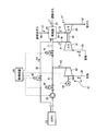
- FIG. 1 is a schematic diagram illustrating a compressed air supply line in a power generation system according to Embodiment 1 of the present invention.
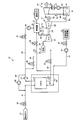
- FIG. 2 is a schematic configuration diagram illustrating a power generation system according to the first embodiment.
- FIG. 3 is a schematic diagram illustrating a compressed air supply line in the power generation system according to the second embodiment of the present invention.
- the power generation system of Example 1 is a triple combined cycle (registered trademark) that combines a solid oxide fuel cell (hereinafter referred to as SOFC), a gas turbine, and a steam turbine.
- SOFC solid oxide fuel cell
- gas turbine gas turbine
- steam turbine a steam turbine.
- This triple combined cycle realizes extremely high power generation efficiency because electricity can be taken out in three stages of SOFC, gas turbine, and steam turbine by installing SOFC upstream of gas turbine combined cycle power generation (GTCC). can do.
- GTCC gas turbine combined cycle power generation
- FIG. 1 is a schematic diagram showing a compressed air supply line in a power generation system according to a first embodiment of the present invention
- FIG. 2 is a schematic configuration diagram showing the power generation system of the first embodiment.
- the power generation system 10 includes a gas turbine 11 and a generator 12, a SOFC 13, a steam turbine 14 and a generator 15.
- the power generation system 10 is configured to obtain high power generation efficiency by combining power generation by the gas turbine 11, power generation by the SOFC 13, and power generation by the steam turbine 14.
- the gas turbine 11 includes a compressor 21, a combustor 22, and a turbine 23, and the compressor 21 and the turbine 23 are coupled to each other by a rotary shaft 24 so as to be integrally rotatable.
- the compressor 21 compresses the air A taken in from the air intake line 25.
- the combustor 22 mixes the compressed air (first compressed air) A1 supplied from the compressor 21 through the first compressed air supply line 26 and the fuel gas L1 supplied from the first fuel gas supply line 27. Burn.
- the turbine 23 is rotated by exhaust gas (combustion gas) G supplied from the combustor 22 through the exhaust gas supply line 28.
- the turbine 23 is supplied with compressed air A1 compressed by the compressor 21 through the passenger compartment, and cools the blades and the like using the compressed air A1 as cooling air.
- the generator 12 is provided on the same axis as the turbine 23 and can generate electric power when the turbine 23 rotates.
- liquefied natural gas LNG is used as the fuel gas L1 supplied to the combustor 22.
- the SOFC 13 generates power by reacting at a predetermined operating temperature by being supplied with high-temperature fuel gas as a reducing agent and high-temperature air (oxygen gas) as an oxidant.
- the SOFC 13 is configured by accommodating an air electrode, a solid electrolyte, and a fuel electrode in a pressure vessel. Compressed air is supplied to the air electrode, and fuel gas is supplied to the fuel electrode to generate power.
- liquefied natural gas LNG
- LNG liquefied natural gas
- the SOFC 13 is connected to a compressed air supply device (compressed air supply unit) 61 via a second compressed air supply line 31, and the compressed air (second compressed air) A ⁇ b> 2 compressed by the compressed air supply device 61 is aired. It can be supplied to the introduction part of the pole.
- the second compressed air supply line 31 is provided with a control valve (first on-off valve) 32 capable of adjusting the amount of air to be supplied and a blower 33 capable of increasing the pressure of the compressed air A2 along the air flow direction.
- the SOFC 13 is connected to an exhaust air line 34 that exhausts exhaust air A3 used at the air electrode.
- the exhaust air line 34 is branched into an exhaust line 35 for exhausting the exhaust air A3 used at the air electrode to the outside, and a compressed air circulation line 36 connected to the combustor 22.
- the discharge line 35 is provided with a control valve 37 capable of adjusting the amount of air discharged
- the compressed air circulation line 36 is provided with a control valve 38 capable of adjusting the amount of air circulated.
- the SOFC 13 is provided with a second fuel gas supply line 41 for supplying the fuel gas L2 to the introduction portion of the fuel electrode.
- the second fuel gas supply line 41 is provided with a control valve 42 that can adjust the amount of fuel gas to be supplied.
- the SOFC 13 is connected to an exhaust fuel line 43 that exhausts the exhaust fuel gas L3 used at the fuel electrode.
- the exhaust fuel line 43 is branched into an exhaust line 44 that discharges to the outside and an exhaust fuel gas supply line 45 that is connected to the combustor 22.
- the discharge line 44 is provided with a control valve 46 capable of adjusting the amount of fuel gas to be discharged.
- the exhaust fuel gas supply line 45 is provided with a control valve 47 capable of adjusting the amount of fuel gas to be supplied, and a blower 48 capable of boosting fuel. Is provided along the flow direction of the fuel gas L3.
- the SOFC 13 is provided with a fuel gas recirculation line 49 that connects the exhaust fuel line 43 and the second fuel gas supply line 41.
- the fuel gas recirculation line 49 is provided with a recirculation blower 50 that recirculates the exhaust fuel gas L3 of the exhaust fuel line 43 to the second fuel gas supply line 41.
- the steam turbine 14 rotates the turbine 52 with the steam generated by the exhaust heat recovery boiler (HRSG) 51.
- the exhaust heat recovery boiler 51 is connected to an exhaust gas line 53 from the gas turbine 11 (the turbine 23), and generates steam S by exchanging heat between the air and the high temperature exhaust gas G.
- the steam turbine 14 (turbine 52) is provided with a steam supply line 54 and a water supply line 55 between the exhaust heat recovery boiler 51.
- the water supply line 55 is provided with a condenser 56 and a water supply pump 57.
- the generator 15 is provided coaxially with the turbine 52 and can generate electric power when the turbine 52 rotates.
- the exhaust gas from which heat has been recovered by the exhaust heat recovery boiler 51 is released to the atmosphere after removing harmful substances.
- a compressed air supply device (compressed air supply unit) 61 that can generate compressed air and the compressed air compressed by the compressed air supply device 61 are supplied to the SOFC 13.
- a second compressed air supply line 31 is provided.
- a compressed air supply device 61 that can be driven independently is provided, and the compressor 21 is compressed air only to the combustor 22 (the turbine 23) by the first compressed air supply line 26.
- the compressed air supply device 61 supplies compressed air only to the SOFC 13 through the second compressed air supply line 31. Then, the entire amount of compressed air compressed by the compressor 21 is sent to the combustor 22 and the turbine 23, and the entire amount of compressed air compressed by the compressed air supply device 61 is sent to the SOFC 13. Therefore, fluctuations in the operation state in the gas turbine 11 are not transmitted to the SOFC 13, and the SOFC 13 can be operated stably.
- the SOFC 13 generates power by supplying the compressed air A2 to the air electrode and supplying the fuel gas L2 to the fuel electrode.
- the compressed air A2 and the fuel gas L2 flow between the air electrode and the fuel electrode, and the temperature fluctuates.
- the compressed air A1 compressed by the compressor 21 is not supplied to the SOFC 13, but only the compressed air A2 compressed by the compressed air supply device 61 is supplied to the SOFC 13. Therefore, the SOFC 13 is the air electrode. The pressure does not fluctuate and the SOFC 13 can be stably operated.
- the compressed air supply device 61 is configured by connecting a SOFC compressor (fuel cell compressor) 62 and a SOFC steam turbine (fuel cell steam turbine) 63 so as to be integrally rotatable by a connecting shaft 64.
- the second compressed air supply line 31 has one end connected to the SOFC compressor 62 and the other end connected to the SOFC 13.
- the SOFC compressor 62 receives the air taken in from the air intake line 65. Compress. Further, the SOFC compressor 62 can be driven by rotating the SOFC steam turbine 63 by the steam generated by the exhaust heat recovery boiler 51 to compress the air.
- one end of the steam supply line 66 is connected to the steam supply line 54 that supplies steam from the exhaust heat recovery boiler 51 to the steam turbine 14 (turbine 52), and the other end is connected to the SOFC steam turbine 63. Yes.
- the steam supply line 66 is provided with a control valve 67 capable of adjusting the amount of steam to be supplied.
- the control device 68 can adjust at least the opening degrees of the control valve 32 and the control valve 67 and can control the drive and stop of the blower 33. Therefore, the control device 68 opens the control valves 32 and 67 during the steady operation of the SOFC 13 and supplies the steam generated in the exhaust heat recovery boiler 51 to the SOFC steam turbine 63 from the steam supply line 54 to compress the SOFC.
- the machine 62 is driven.
- a bypass line 71 that connects the first compressed air supply line 26 and the second compressed air supply line 31 is provided, and a control valve (second on-off valve) 72 that can adjust the flow rate of the compressed air to the bypass line 71.
- the control device 68 can adjust the opening degree of the control valve 72. Specifically, the control device 68 closes the control valve 72 during the steady operation of the SOFC 13 so that the compressed air A2 generated by the compressed air supply device 61 is not supplied to the gas turbine 11, but only to the SOFC 13. Supplied. On the other hand, when the SOFC 13 is stopped, the control valve 72 is opened while the control valve 32 is closed, so that the compressed air generated by the compressed air supply device 61 is not supplied to the SOFC 13 but supplied only to the gas turbine 11. Is done.
- the control device 68 can control not only the control valve 32 and the control valve 67 but also other control valves.
- the compressor 21 compresses the air A
- the combustor 22 mixes and burns the compressed air A1 and the fuel gas L1
- the turbine 23 is rotated by the exhaust gas G. 12 starts power generation.
- the turbine 52 is rotated by the steam S generated by the exhaust heat recovery boiler 51, whereby the generator 15 starts power generation.
- the control valve 67 is opened to supply the steam generated in the exhaust heat recovery boiler 51 from the steam supply line 66 to the SOFC steam turbine 63 of the compressed air supply device 61. Then, the SOFC steam turbine 63 starts rotating by the supplied steam, and the SOFC compressor 62 is driven to rotate synchronously, thereby compressing the air A taken in from the air intake line 65. Then, the SOFC compressor 62 supplies the compressed air A2 from the second compressed air supply line 31 to the SOFC 13 and starts pressure increase.
- control valve 37 of the discharge line 35 and the control valve 38 of the compressed air circulation line 36 are closed, and the control valve 32 is opened while the blower 33 of the second compressed air supply line 31 is stopped.
- the compressed air A2 compressed by the compressed air supply device 61 is supplied from the second compressed air supply line 31 to the SOFC 13 side.
- the pressure on the SOFC 13 side increases as the compressed air A2 is supplied.
- the fuel gas L2 is supplied to the fuel electrode side and pressure increase is started.
- the control valve 46 of the exhaust line 44 and the control valve 47 of the exhaust fuel gas supply line 45 closed and the blower 48 stopped, the control valve 42 of the second fuel gas supply line 41 is opened and the fuel gas is recirculated.
- the recirculation blower 50 of the line 49 is driven.
- the fuel gas L2 is supplied from the second fuel gas supply line 41 to the SOFC 13 side, and the exhaust fuel gas L3 is recirculated by the fuel gas recirculation line 49.
- the pressure on the SOFC 13 side is increased by supplying the fuel gas L2.
- the control valve 32 When the pressure on the air electrode side of the SOFC 13 reaches a predetermined pressure, the control valve 32 is fully opened and the blower 33 is driven. At the same time, the control valve 37 is opened and the exhaust air A3 from the SOFC 13 is exhausted from the exhaust line 35. Then, the compressed air A2 is supplied to the SOFC 13 side by the blower 33. At the same time, the control valve 46 is opened, and the exhaust fuel gas L3 from the SOFC 13 is discharged from the discharge line 44. When the pressure on the air electrode side and the pressure on the fuel electrode side in the SOFC 13 reach the target pressure, the pressure increase of the SOFC 13 is completed.
- the compressed air supply device 61 and the blower 33 are provided.
- the blower 33 may be eliminated by controlling the compressed air supply device 61. That is, by adjusting the opening of the control valve 67, the amount of steam supplied to the SOFC steam turbine 63 is adjusted, and the amount of compressed air A2 generated by the SOFC compressor 62 is adjusted, thereby returning to the SOFC 13.
- the SOFC 13 may be boosted by adjusting the supply amount of the compressed air A2.
- the opening / closing control of the control valve 32 and the start-up control of the blower 33 are unnecessary, and the cost can be reduced.
- the control valve 37 is closed and the control valve 38 is opened.
- the exhaust air A3 from the SOFC 13 is supplied to the combustor 22 from the compressed air circulation line 36.
- the control valve 46 is closed, while the control valve 47 is opened to drive the blower 48.
- the exhaust fuel gas L3 from the SOFC 13 is supplied from the exhaust fuel gas supply line 45 to the combustor 22.
- the fuel gas L1 supplied from the first fuel gas supply line 27 to the combustor 22 is reduced.
- the combustor 22 and the turbine 23 of the gas turbine 11 are supplied with the entire amount of compressed air A1 compressed by the compressor 21, and the SOFC 13 is supplied with the entire amount of compressed air A2 compressed by the compressed air supply device 61. . Therefore, even if the output fluctuation occurs in the gas turbine 11 and the pressure of the air A1 compressed by the compressor 21 fluctuates, the pressure of the air A2 supplied to the SOFC 13 does not fluctuate. Therefore, in the SOFC 13, the pressure of the air electrode does not fluctuate, the pressure of the air electrode and the pressure of the fuel electrode are almost equal, and the SOFC 13 is stably operated regardless of the operating state of the gas turbine 11.
- the control device 68 opens the control valve 72 while the SOFC 13 is stopped, and closes the control valve 32 so that the compressed air A2 generated by the compressed air supply device 61 is generated.
- the gas turbine 11 is supplied without being supplied to the SOFC 13.
- the compressed air A2 generated by the compressed air supply device 61 is supplied to the SOFC 13, and the used exhaust air A3 is supplied from the compressed air circulation line 36 to the combustor 22 of the gas turbine 11. . Therefore, when the operation of the SOFC 13 is stopped, the compressed air A2 generated by the compressed air supply device 61 is supplied directly from the bypass line 71 to the combustor 22 of the gas turbine 11 without being supplied to the SOFC 13.
- the gas turbine 11 is supplied with substantially the same amount of compressed air A2 when the SOFC 13 is in steady operation and when it is stopped, and stable power generation is possible by enabling full-load operation.
- the exhaust fuel gas is not supplied from the SOFC 13 to the combustor 22 of the gas turbine 11, so that it is necessary to increase the amount of fuel gas from the first fuel gas supply line 27.
- the gas turbine 11 including the compressor 21, the combustor 22, and the turbine 23, and the first compressed air that supplies the compressed air compressed by the compressor 21 to the combustor 22.
- Supply line 26, SOFC 13 having air electrode and fuel electrode, compressed air supply device 61 capable of generating compressed air, and second compressed air supply line 31 for supplying compressed air compressed by compressed air supply device 61 to SOFC 13 And are provided.
- the compressed air supply device 61 is provided separately from the compressor 21 of the gas turbine 11, and the air A 1 compressed by the compressor 21 is supplied to the combustor 22 through the first compressed air supply line 26, and the compressed air supply device 61.
- the compressed air A2 is supplied to the SOFC 13 through the second compressed air supply line 31. Therefore, even if the pressure of the air supplied to the combustor 22 fluctuates according to the operating state of the gas turbine 11, the pressure of the air supplied to the SOFC 13 does not fluctuate. As a result, the pressure of the air electrode does not fluctuate in the SOFC 13, the pressure of the air electrode and the pressure of the fuel electrode are almost equal, and the SOFC 13 can be stably operated regardless of the operating state of the gas turbine 11. .
- the exhaust heat recovery boiler 51 that generates steam from the exhaust gas from the gas turbine 11 and the steam turbine 14 that is driven by the steam generated in the exhaust heat recovery boiler 51 are provided, and the compressed air supply device 61 is provided.
- a SOFC compressor 62 and a steam supply line 66 for supplying steam generated by the exhaust heat recovery boiler 51 to the SOFC steam turbine 63 are provided. Therefore, when the steam generated in the exhaust heat recovery boiler 51 is supplied to the SOFC steam turbine 63 through the steam supply line 66, the SOFC steam turbine 63 drives the SOFC compressor 62 by being driven by the steam. Thus, compressed air A2 is generated, and this compressed air A2 is supplied to the SOFC 13.
- the power generation system 10 is a combination of the SOFC 13, the gas turbine 11, and the steam turbine 14, and the compressed air A 2 is generated by driving the SOFC compressor 62 with the steam generated in the system of the power generation system 10. Is supplied to the SOFC 13, and the overall system efficiency can be improved.
- a control valve 32 that can open and close the second compressed air supply line 31, a bypass line 71 that connects the first compressed air supply line 36 and the second compressed air supply line 31, and a bypass line A control valve 72 for opening and closing 71 is provided. Therefore, the compressed air A2 generated by driving the SOFC compressor 62 can be supplied to the combustor 22 from the bypass line 71, and the amount of compressed air is adjusted according to the operating state of the gas turbine 11 and the SOFC 13. be able to.
- a control device 68 capable of opening and closing the control valve 32 and the control valve 72 is provided.
- the control device 68 closes the control valve 32 when the SOFC 13 is stopped, and opens the control valve 72. ing. Therefore, when the SOFC 13 is stopped, the control valve 32 is closed to stop the supply of the compressed air A2 from the compressed air supply device 61 to the SOFC 13, and the control valve 72 is opened to combust the gas turbine 11 from the compressed air supply device 61.
- the supply of the compressed air A2 to the vessel 22 is started, the amount of compressed air in the gas turbine 11 is ensured, and the gas turbine 11 can be operated stably.
- FIG. 3 is a schematic view showing a compressed air supply line in the power generation system according to Embodiment 2 of the present invention.
- the basic configuration of the power generation system of the present embodiment is substantially the same as that of the first embodiment described above, and will be described with reference to FIG. 2 and the member having the same function as that of the first embodiment described above. Are denoted by the same reference numerals, and detailed description thereof is omitted.
- the SOFC 13 is connected to a compressed air supply device (compressed air supply unit) 81 via a second compressed air supply line 31.
- the compressed air A2 compressed by the supply device 81 can be supplied to the introduction portion of the air electrode. That is, separately from the compressor 21 of the gas turbine 11, a compressed air supply device 81 that can be driven independently is provided, and the compressor 21 is compressed air only to the combustor 22 (the turbine 23) by the first compressed air supply line 26. A1 is supplied, and the compressed air supply device 81 supplies the compressed air A2 only to the SOFC 13 through the second compressed air supply line 31.
- the entire amount of compressed air compressed by the compressor 21 is sent to the combustor 22 and the turbine 23, and the entire amount of compressed air compressed by the compressed air supply device 81 is sent to the SOFC 13. Therefore, fluctuations in the operation state in the gas turbine 11 are not transmitted to the SOFC 13, and the SOFC 13 can be operated stably.
- the compressed air supply device 81 is configured by connecting a SOFC compressor (fuel cell compressor) 82 and a drive motor 83 by a connecting shaft 84.
- the second compressed air supply line 31 has one end connected to the SOFC compressor 82 and the other end connected to the SOFC 13.
- the SOFC compressor 82 receives the air taken in from the air intake line 85. Compress.
- the SOFC compressor 82 is driven by supplying electric power to the drive motor 83 and can compress air.
- the control device 68 can adjust at least the opening degrees of the control valve 32 and the control valve 72 and can control the driving and stopping of the driving motor 63. Therefore, the control device 68 opens the control valves 32 and 67 and drives the drive motor 63 to drive the SOFC compressor 82 during steady operation of the SOFC 13.
- a bypass line 71 for connecting the first compressed air supply line 26 and the second compressed air supply line 31 is provided, and a control valve 72 capable of adjusting the flow rate of the compressed air is provided in the bypass line 71.
- the control device 68 closes the control valve 72 during the steady operation of the SOFC 13 so that the compressed air generated by the compressed air supply device 81 is not supplied to the gas turbine 11 but is supplied only to the SOFC 13.
- the control valve 72 is opened while the control valve 32 is closed, so that the compressed air generated by the compressed air supply device 81 is not supplied to the SOFC 13 but supplied only to the gas turbine 11. Is done.
- the gas turbine 11, the steam turbine 14, and the SOFC 13 are started in this order, but the SOFC 13 may be started before the gas turbine 11 is started.
- the SOFC compressor 82 When the SOFC 13 is operated, by driving the drive motor 83, the SOFC compressor 82 is rotationally driven to compress the air A taken in from the air intake line 85.
- the SOFC compressor 82 supplies the compressed air A2 from the second compressed air supply line 31 to the SOFC 13.
- the fuel gas L2 is supplied from the second fuel gas supply line 41 to the SOFC 13. Then, the compressed air A2 and the fuel gas L2 react with each other in the SOFC 13 to generate power.
- the combustor 22 and the turbine 23 of the gas turbine 11 are supplied with the entire amount of air A1 compressed by the compressor 21, and the SOFC 13 is supplied with the entire amount of air A2 compressed by the compressed air supply device 81. Therefore, even if the output fluctuation occurs in the gas turbine 11 and the pressure of the air A1 compressed by the compressor 21 fluctuates, the pressure of the air A2 supplied to the SOFC 13 does not fluctuate, and the operating state of the gas turbine 11 Regardless, the SOFC 13 is stably operated.
- the gas turbine 11 including the compressor 21, the combustor 22, and the turbine 23, and the first compressed air that supplies the compressed air compressed by the compressor 21 to the combustor 22.
- the compressed air supply device 81 is provided separately from the compressor 21 of the gas turbine 11, and the air A 1 compressed by the compressor 21 is supplied to the combustor 22 through the first compressed air supply line 26, and the compressed air supply device 81.
- the compressed air A2 is supplied to the SOFC 13 through the second compressed air supply line 31. Therefore, even if the pressure of the air supplied to the combustor 22 fluctuates according to the operating state of the gas turbine 11, the pressure of the air supplied to the SOFC 13 does not fluctuate. As a result, the SOFC 13 can be stably operated regardless of the operation state of the gas turbine 11.
- an SOFC compressor 82 and a drive motor 83 that drives the SOFC compressor 82 are provided as the compressed air supply device 81. Accordingly, the drive motor 83 drives the SOFC compressor 82 to generate the compressed air A2, and the compressed air A2 is supplied to the SOFC 13.
- the compressed air A2 can be supplied to the SOFC 13 independently of the gas turbine 11, and stable operation of the SOFC 13 can be ensured with a simple configuration.
- the first on-off valve and the second on-off valve of the present invention are the control valves 32 and 72 capable of adjusting the flow rate, but may be shut-off valves that cannot adjust the flow rate.
Landscapes
- Engineering & Computer Science (AREA)
- Chemical & Material Sciences (AREA)
- Combustion & Propulsion (AREA)
- Mechanical Engineering (AREA)
- General Engineering & Computer Science (AREA)
- Manufacturing & Machinery (AREA)
- Life Sciences & Earth Sciences (AREA)
- Sustainable Development (AREA)
- Sustainable Energy (AREA)
- Chemical Kinetics & Catalysis (AREA)
- Electrochemistry (AREA)
- General Chemical & Material Sciences (AREA)
- Fuel Cell (AREA)
- Engine Equipment That Uses Special Cycles (AREA)
Abstract
Description
11 ガスタービン
12 発電機
13 固体酸化物形燃料電池(SOFC)
14 蒸気タービン
15 発電機
21 圧縮機
22 燃焼器
23 タービン
26 第1圧縮空気供給ライン
27 第1燃料ガス供給ライン
31 第2圧縮空気供給ライン
32 制御弁(第1開閉弁)
33 ブロワ
34 排空気ライン
36 圧縮空気循環ライン
41 第2燃料ガス供給ライン
42 制御弁
43 排燃料ライン
45 排燃料ガス供給ライン
49 燃料ガス再循環ライン
61 圧縮空気供給装置(圧縮空気供給部)
62 SOFC用圧縮機(燃料電池用圧縮機)
63 SOFC用蒸気タービン(燃料電池用蒸気タービン)
66 蒸気供給ライン
67 制御弁
71 バイパスライン
72 制御弁(第2開閉弁)
Claims (5)
- 圧縮機と燃焼器を有するガスタービンと、
前記圧縮機で圧縮した第1圧縮空気を前記燃焼器に供給する第1圧縮空気供給ラインと、
空気極及び燃料極を有する燃料電池と、
第2圧縮空気を生成可能な圧縮空気供給部と、
前記圧縮空気供給部で圧縮した第2圧縮空気を前記燃料電池に供給する第2圧縮空気供給ラインと、
を有することを特徴とする発電システム。 - 前記ガスタービンからの排ガスにより蒸気を生成する排熱回収ボイラと、前記排熱回収ボイラで生成された蒸気により駆動する蒸気タービンとが設けられ、前記圧縮空気供給部は、蒸気による駆動する燃料電池用圧縮機と、前記排熱回収ボイラで生成された蒸気を前記燃料電池用圧縮機に供給する蒸気供給ラインとを有することを特徴とする請求項1に記載の発電システム。
- 前記圧縮空気供給部は、燃料電池用圧縮機と、前記燃料電池用圧縮機を駆動する駆動モータとを有することを特徴とする請求項1に記載の発電システム。
- 前記第2圧縮空気供給ラインを開閉可能な第1開閉弁と、前記第1圧縮空気供給ラインと前記第2圧縮空気供給ラインとを接続するバイパスラインと、前記バイパスラインを開閉する第2開閉弁とが設けられることを特徴とする請求項1から3のいずれか一つに記載の発電システム。
- 前記第1開閉弁及び第2開閉弁を開閉制御可能な制御部が設けられ、前記制御部は、前記燃料電池の停止時に前記第1開閉弁を閉止する一方、前記第2開閉弁を開放することを特徴とする請求項4に記載の発電システム。
Priority Applications (6)
| Application Number | Priority Date | Filing Date | Title |
|---|---|---|---|
| KR1020157011133A KR101680503B1 (ko) | 2012-10-31 | 2013-10-28 | 발전 시스템 |
| DE112013005205.9T DE112013005205B4 (de) | 2012-10-31 | 2013-10-28 | Stromerzeugungssystem |
| KR1020167023015A KR101688376B1 (ko) | 2012-10-31 | 2013-10-28 | 발전 시스템 |
| CN201380056427.7A CN104755723B (zh) | 2012-10-31 | 2013-10-28 | 发电系统 |
| US14/439,073 US9777629B2 (en) | 2012-10-31 | 2013-10-28 | Power generation system |
| US15/609,799 US10533495B2 (en) | 2012-10-31 | 2017-05-31 | Power generation system |
Applications Claiming Priority (2)
| Application Number | Priority Date | Filing Date | Title |
|---|---|---|---|
| JP2012-240726 | 2012-10-31 | ||
| JP2012240726A JP6109529B2 (ja) | 2012-10-31 | 2012-10-31 | 発電システム |
Related Child Applications (2)
| Application Number | Title | Priority Date | Filing Date |
|---|---|---|---|
| US14/439,073 A-371-Of-International US9777629B2 (en) | 2012-10-31 | 2013-10-28 | Power generation system |
| US15/609,799 Continuation US10533495B2 (en) | 2012-10-31 | 2017-05-31 | Power generation system |
Publications (1)
| Publication Number | Publication Date |
|---|---|
| WO2014069409A1 true WO2014069409A1 (ja) | 2014-05-08 |
Family
ID=50627314
Family Applications (1)
| Application Number | Title | Priority Date | Filing Date |
|---|---|---|---|
| PCT/JP2013/079151 Ceased WO2014069409A1 (ja) | 2012-10-31 | 2013-10-28 | 発電システム |
Country Status (6)
| Country | Link |
|---|---|
| US (2) | US9777629B2 (ja) |
| JP (1) | JP6109529B2 (ja) |
| KR (2) | KR101688376B1 (ja) |
| CN (2) | CN104755723B (ja) |
| DE (1) | DE112013005205B4 (ja) |
| WO (1) | WO2014069409A1 (ja) |
Families Citing this family (12)
| Publication number | Priority date | Publication date | Assignee | Title |
|---|---|---|---|---|
| JP6109529B2 (ja) * | 2012-10-31 | 2017-04-05 | 三菱日立パワーシステムズ株式会社 | 発電システム |
| DE112013005578B4 (de) * | 2012-11-21 | 2022-05-05 | Mitsubishi Heavy Industries, Ltd. | Energieerzeugungssystem, Antriebsverfahren für Energieerzeugungssystem |
| CA2956120C (en) * | 2014-07-24 | 2019-05-14 | Nissan Motor Co., Ltd. | Fuel cell system |
| JP5778369B1 (ja) * | 2015-05-13 | 2015-09-16 | 隆逸 小林 | 高密度空気の製造方法及び利用方法 |
| US10907640B2 (en) * | 2016-02-16 | 2021-02-02 | Apgn Inc. | Gas turbine blower/pump |
| US11008938B2 (en) | 2016-02-16 | 2021-05-18 | Apgn Inc. | Gas turbine blower/pump |
| CN108886153B (zh) * | 2016-03-22 | 2019-11-29 | 日产自动车株式会社 | 燃料电池系统以及燃料电池系统的控制方法 |
| KR102423941B1 (ko) * | 2016-12-08 | 2022-07-22 | 아틀라스 콥코 콤텍트, 엘엘씨 | 폐열 회수 시스템 |
| US10724432B2 (en) * | 2017-11-07 | 2020-07-28 | General Electric Company | Integrated fuel cell and engine combustor assembly |
| AT521209B1 (de) * | 2018-05-03 | 2020-11-15 | Avl List Gmbh | Brennstoffzellensystem, stationäres Kraftwerk sowie Verfahren zum Betreiben eines Brennstoffzellensystems |
| CN109361000B (zh) * | 2018-09-04 | 2020-11-06 | 新地能源工程技术有限公司 | 整体煤气化固体氧化物燃料电池-蒸汽轮机联合发电系统及工艺 |
| WO2020101929A1 (en) | 2018-11-14 | 2020-05-22 | Precision Combustion, Inc. | Integrated power generation system |
Citations (2)
| Publication number | Priority date | Publication date | Assignee | Title |
|---|---|---|---|---|
| JPH1012255A (ja) * | 1996-06-17 | 1998-01-16 | Tokyo Electric Power Co Inc:The | 燃料電池発電システム及び複合発電プラント |
| JP2003036872A (ja) * | 2001-07-19 | 2003-02-07 | Mitsubishi Heavy Ind Ltd | 複合発電システム |
Family Cites Families (48)
| Publication number | Priority date | Publication date | Assignee | Title |
|---|---|---|---|---|
| JPH0112255Y2 (ja) * | 1979-09-18 | 1989-04-11 | ||
| JPH0789494B2 (ja) | 1986-05-23 | 1995-09-27 | 株式会社日立製作所 | 複合発電プラント |
| JPH0286926A (ja) * | 1988-09-26 | 1990-03-27 | Hitachi Ltd | Lngから発生するbogの有効な処理方法、及び、lngを燃料とする複合発電プラント |
| JPH02172159A (ja) * | 1988-12-24 | 1990-07-03 | Ishikawajima Harima Heavy Ind Co Ltd | 溶融炭酸塩型燃料電池発電方法及び装置 |
| JPH0491324A (ja) * | 1990-08-06 | 1992-03-24 | Central Res Inst Of Electric Power Ind | 二酸化炭素回収型火力発電システム |
| US5968680A (en) * | 1997-09-10 | 1999-10-19 | Alliedsignal, Inc. | Hybrid electrical power system |
| JP3072630B2 (ja) * | 1997-12-15 | 2000-07-31 | 溶融炭酸塩型燃料電池発電システム技術研究組合 | 燃料電池複合発電装置 |
| JP2000123846A (ja) * | 1998-10-19 | 2000-04-28 | Aisin Seiki Co Ltd | 燃料電池システム |
| US6655325B1 (en) * | 1999-02-01 | 2003-12-02 | Delphi Technologies, Inc. | Power generation system and method with exhaust side solid oxide fuel cell |
| US6230494B1 (en) * | 1999-02-01 | 2001-05-15 | Delphi Technologies, Inc. | Power generation system and method |
| JP2001052727A (ja) * | 1999-08-04 | 2001-02-23 | Mitsubishi Heavy Ind Ltd | 燃料電池発電システム |
| JP4508338B2 (ja) * | 2000-02-17 | 2010-07-21 | 電源開発株式会社 | 発電システム |
| US20020100836A1 (en) * | 2001-01-31 | 2002-08-01 | Hunt Robert Daniel | Hydrogen and oxygen battery, or hudrogen and oxygen to fire a combustion engine and/or for commerce. |
| US6499303B1 (en) * | 2001-04-18 | 2002-12-31 | General Electric Company | Method and system for gas turbine power augmentation |
| JP2003045444A (ja) * | 2001-07-31 | 2003-02-14 | Japan Climate Systems Corp | 燃料電池の排気活用装置 |
| US6641084B1 (en) * | 2002-06-21 | 2003-11-04 | The Boeing Company | Solid oxide fuel cell as auxiliary power source installation in transport aircraft |
| US7410713B2 (en) * | 2002-12-23 | 2008-08-12 | General Electric Company | Integrated fuel cell hybrid power plant with re-circulated air and fuel flow |
| US7153599B2 (en) * | 2002-12-23 | 2006-12-26 | General Electric Company | Cooled turbine integrated fuel cell hybrid power plant |
| JP4579560B2 (ja) * | 2003-06-30 | 2010-11-10 | 川崎重工業株式会社 | 燃料電池・常圧タービン・ハイブリッドシステム |
| US7604883B2 (en) * | 2003-07-17 | 2009-10-20 | Chrysler Group Llc | Thermal integration of pressurized fuel cell systems with an expander and a heat exchanger coupled to the fuel cell for receiving waste heat from the housing of the fuel cell |
| US7150143B2 (en) * | 2003-07-21 | 2006-12-19 | General Electric Company | Hybrid fuel cell-pulse detonation power system |
| US7344787B2 (en) * | 2003-10-29 | 2008-03-18 | General Motors Corporation | Two-stage compression for air supply of a fuel cell system |
| JP2006114373A (ja) * | 2004-10-15 | 2006-04-27 | Dainippon Printing Co Ltd | 単室型固体酸化物形燃料電池発電システム |
| EP1804322B1 (en) * | 2004-10-19 | 2011-12-14 | Central Research Institute of Electric Power Industry | Combined power generation equipment |
| US7184875B2 (en) * | 2004-12-14 | 2007-02-27 | General Electric Company | High temperature protection of hybrid fuel cell system combustor and other components VIA water or water vapor injection |
| DE102008006953B4 (de) * | 2008-01-31 | 2010-09-02 | Airbus Deutschland Gmbh | System und Verfahren zur Reduktion von Schadstoffen in Triebwerksabgasen |
| JP5185657B2 (ja) | 2008-02-27 | 2013-04-17 | 三菱重工業株式会社 | コンバインドシステム |
| JP2009283178A (ja) * | 2008-05-20 | 2009-12-03 | Sanden Corp | 燃料電池システム |
| JP2010146934A (ja) | 2008-12-22 | 2010-07-01 | Mitsubishi Heavy Ind Ltd | 固体酸化物形燃料電池および固体酸化物形燃料電池システム |
| GB2469043B (en) | 2009-03-30 | 2011-02-23 | Lotus Car | A reheated gas turbine system having a fuel cell |
| US9083020B2 (en) * | 2009-09-04 | 2015-07-14 | Lg Fuel Cell Systems Inc. | Reducing gas generators and methods for generating reducing gas |
| CN102456898B (zh) * | 2010-10-20 | 2017-06-30 | 上海新奥能源科技有限公司 | 燃料电池燃气轮机热电联产系统 |
| JP2011229961A (ja) | 2011-07-13 | 2011-11-17 | Sammy Corp | 弾球遊技機 |
| US9979033B2 (en) * | 2012-10-31 | 2018-05-22 | Mitsubishi Hitachi Power Systems, Ltd. | Power generation system and method for activating fuel cell in power generation system |
| JP6071430B2 (ja) * | 2012-10-31 | 2017-02-01 | 三菱日立パワーシステムズ株式会社 | 発電システム及び発電システムの運転方法 |
| JP6109529B2 (ja) * | 2012-10-31 | 2017-04-05 | 三菱日立パワーシステムズ株式会社 | 発電システム |
| WO2014069408A1 (ja) * | 2012-10-31 | 2014-05-08 | 三菱重工業株式会社 | 発電システム及び発電システムにおける燃料電池の起動方法並びに運転方法 |
| JP5896885B2 (ja) * | 2012-11-13 | 2016-03-30 | 三菱日立パワーシステムズ株式会社 | 発電システム及び発電システムの運転方法 |
| DE112013005578B4 (de) * | 2012-11-21 | 2022-05-05 | Mitsubishi Heavy Industries, Ltd. | Energieerzeugungssystem, Antriebsverfahren für Energieerzeugungssystem |
| JP6004915B2 (ja) * | 2012-11-22 | 2016-10-12 | 三菱日立パワーシステムズ株式会社 | 発電システム及び発電システムの運転方法 |
| JP5769695B2 (ja) * | 2012-12-25 | 2015-08-26 | 三菱日立パワーシステムズ株式会社 | 発電システム及び発電システムの停止方法 |
| JP6125224B2 (ja) * | 2012-12-25 | 2017-05-10 | 三菱日立パワーシステムズ株式会社 | 発電システム及び発電システムの運転方法 |
| JP6100012B2 (ja) * | 2013-02-06 | 2017-03-22 | 三菱日立パワーシステムズ株式会社 | 発電システム及び発電システムの運転方法 |
| JP6053560B2 (ja) * | 2013-02-20 | 2016-12-27 | 三菱日立パワーシステムズ株式会社 | 発電システム及び発電システムの運転方法 |
| US10622653B2 (en) * | 2013-03-14 | 2020-04-14 | Battelle Memorial Institute | High power density solid oxide fuel cell steam reforming system and process for electrical generation |
| WO2014151214A1 (en) * | 2013-03-15 | 2014-09-25 | Exxonmobil Research And Engineering Company | Integration of molten carbonate fuel cells in fischer-tropsch synthesis |
| US9885283B2 (en) * | 2014-06-05 | 2018-02-06 | Rolls-Royce Corporation | Gas turbine engine driven by supercritical power generation system |
| CN105576268B (zh) * | 2014-10-08 | 2019-02-15 | 通用电气公司 | 用于控制流量比的系统和方法 |
-
2012
- 2012-10-31 JP JP2012240726A patent/JP6109529B2/ja active Active
-
2013
- 2013-10-28 KR KR1020167023015A patent/KR101688376B1/ko active Active
- 2013-10-28 KR KR1020157011133A patent/KR101680503B1/ko active Active
- 2013-10-28 WO PCT/JP2013/079151 patent/WO2014069409A1/ja not_active Ceased
- 2013-10-28 CN CN201380056427.7A patent/CN104755723B/zh active Active
- 2013-10-28 US US14/439,073 patent/US9777629B2/en active Active
- 2013-10-28 CN CN201610444529.1A patent/CN106089342B/zh active Active
- 2013-10-28 DE DE112013005205.9T patent/DE112013005205B4/de active Active
-
2017
- 2017-05-31 US US15/609,799 patent/US10533495B2/en active Active
Patent Citations (2)
| Publication number | Priority date | Publication date | Assignee | Title |
|---|---|---|---|---|
| JPH1012255A (ja) * | 1996-06-17 | 1998-01-16 | Tokyo Electric Power Co Inc:The | 燃料電池発電システム及び複合発電プラント |
| JP2003036872A (ja) * | 2001-07-19 | 2003-02-07 | Mitsubishi Heavy Ind Ltd | 複合発電システム |
Also Published As
| Publication number | Publication date |
|---|---|
| KR20150063504A (ko) | 2015-06-09 |
| KR101680503B1 (ko) | 2016-11-28 |
| KR101688376B1 (ko) | 2016-12-20 |
| CN104755723A (zh) | 2015-07-01 |
| US20170260902A1 (en) | 2017-09-14 |
| JP2014088861A (ja) | 2014-05-15 |
| KR20160103179A (ko) | 2016-08-31 |
| DE112013005205B4 (de) | 2021-09-16 |
| CN106089342B (zh) | 2017-10-13 |
| JP6109529B2 (ja) | 2017-04-05 |
| CN106089342A (zh) | 2016-11-09 |
| DE112013005205T5 (de) | 2015-09-10 |
| US20150345386A1 (en) | 2015-12-03 |
| US9777629B2 (en) | 2017-10-03 |
| CN104755723B (zh) | 2016-06-15 |
| US10533495B2 (en) | 2020-01-14 |
Similar Documents
| Publication | Publication Date | Title |
|---|---|---|
| JP6109529B2 (ja) | 発電システム | |
| US10490832B2 (en) | Power generation system and method for activating fuel cell in power generation system | |
| JP6228752B2 (ja) | 発電システム及び発電システムの起動方法 | |
| JP5185659B2 (ja) | コンバインドシステム | |
| US9806358B2 (en) | Power generation system, and methods for starting and operating fuel cell in power generation system | |
| JP2009205930A (ja) | コンバインドシステム | |
| JP6071428B2 (ja) | 発電システム及び発電システムにおける燃料電池の起動方法 | |
| WO2014069414A1 (ja) | 発電システム及び発電システムの運転方法 | |
| WO2014112210A1 (ja) | 発電システム | |
| JP6049421B2 (ja) | 発電システム及び発電システムの運転方法 | |
| WO2014073547A1 (ja) | 発電システム及び発電システムにおける燃料電池排気の冷却方法 | |
| JP6276880B2 (ja) | 発電システム | |
| JP5730223B2 (ja) | コンバインド発電システム | |
| JP6087591B2 (ja) | 発電システム及び発電システムにおける燃料電池の起動方法 | |
| JP6057670B2 (ja) | 発電システム及び発電システムにおける燃料電池の運転方法 | |
| JP6087585B2 (ja) | 発電システム及び発電システムにおける燃料電池の起動方法 | |
| JP5984709B2 (ja) | 発電システム及び発電システムの駆動方法 |
Legal Events
| Date | Code | Title | Description |
|---|---|---|---|
| 121 | Ep: the epo has been informed by wipo that ep was designated in this application |
Ref document number: 13851816 Country of ref document: EP Kind code of ref document: A1 |
|
| ENP | Entry into the national phase |
Ref document number: 20157011133 Country of ref document: KR Kind code of ref document: A |
|
| WWE | Wipo information: entry into national phase |
Ref document number: 14439073 Country of ref document: US |
|
| WWE | Wipo information: entry into national phase |
Ref document number: 1120130052059 Country of ref document: DE Ref document number: 112013005205 Country of ref document: DE |
|
| 122 | Ep: pct application non-entry in european phase |
Ref document number: 13851816 Country of ref document: EP Kind code of ref document: A1 |