WO2014069283A1 - 放電電極 - Google Patents
放電電極 Download PDFInfo
- Publication number
- WO2014069283A1 WO2014069283A1 PCT/JP2013/078556 JP2013078556W WO2014069283A1 WO 2014069283 A1 WO2014069283 A1 WO 2014069283A1 JP 2013078556 W JP2013078556 W JP 2013078556W WO 2014069283 A1 WO2014069283 A1 WO 2014069283A1
- Authority
- WO
- WIPO (PCT)
- Prior art keywords
- raw material
- discharge electrode
- temperature plasma
- discharge
- electrodes
- Prior art date
Links
- 239000002994 raw material Substances 0.000 claims description 142
- 230000001678 irradiating effect Effects 0.000 claims description 2
- 230000002093 peripheral effect Effects 0.000 abstract description 20
- 239000000463 material Substances 0.000 abstract description 12
- 238000000034 method Methods 0.000 description 7
- 230000005855 radiation Effects 0.000 description 5
- 239000007788 liquid Substances 0.000 description 4
- 239000011888 foil Substances 0.000 description 3
- 239000002184 metal Substances 0.000 description 3
- ATJFFYVFTNAWJD-UHFFFAOYSA-N Tin Chemical compound [Sn] ATJFFYVFTNAWJD-UHFFFAOYSA-N 0.000 description 2
- 230000015572 biosynthetic process Effects 0.000 description 2
- 239000000470 constituent Substances 0.000 description 2
- 238000011109 contamination Methods 0.000 description 2
- 238000001816 cooling Methods 0.000 description 2
- 238000010586 diagram Methods 0.000 description 2
- 230000000694 effects Effects 0.000 description 2
- 239000004065 semiconductor Substances 0.000 description 2
- 239000007787 solid Substances 0.000 description 2
- 230000001276 controlling effect Effects 0.000 description 1
- 238000000605 extraction Methods 0.000 description 1
- -1 for example Substances 0.000 description 1
- 230000005484 gravity Effects 0.000 description 1
- 238000010438 heat treatment Methods 0.000 description 1
- 239000000155 melt Substances 0.000 description 1
- 230000003287 optical effect Effects 0.000 description 1
- 230000001105 regulatory effect Effects 0.000 description 1
- 108010063955 thrombin receptor peptide (42-47) Proteins 0.000 description 1
Images


Classifications
-
- H—ELECTRICITY
- H05—ELECTRIC TECHNIQUES NOT OTHERWISE PROVIDED FOR
- H05B—ELECTRIC HEATING; ELECTRIC LIGHT SOURCES NOT OTHERWISE PROVIDED FOR; CIRCUIT ARRANGEMENTS FOR ELECTRIC LIGHT SOURCES, IN GENERAL
- H05B41/00—Circuit arrangements or apparatus for igniting or operating discharge lamps
- H05B41/14—Circuit arrangements
- H05B41/30—Circuit arrangements in which the lamp is fed by pulses, e.g. flash lamp
-
- H—ELECTRICITY
- H05—ELECTRIC TECHNIQUES NOT OTHERWISE PROVIDED FOR
- H05G—X-RAY TECHNIQUE
- H05G2/00—Apparatus or processes specially adapted for producing X-rays, not involving X-ray tubes, e.g. involving generation of a plasma
- H05G2/001—Production of X-ray radiation generated from plasma
- H05G2/003—Production of X-ray radiation generated from plasma the plasma being generated from a material in a liquid or gas state
- H05G2/005—Production of X-ray radiation generated from plasma the plasma being generated from a material in a liquid or gas state containing a metal as principal radiation generating component
-
- H—ELECTRICITY
- H01—ELECTRIC ELEMENTS
- H01J—ELECTRIC DISCHARGE TUBES OR DISCHARGE LAMPS
- H01J61/00—Gas-discharge or vapour-discharge lamps
- H01J61/02—Details
- H01J61/04—Electrodes; Screens; Shields
- H01J61/06—Main electrodes
-
- H—ELECTRICITY
- H05—ELECTRIC TECHNIQUES NOT OTHERWISE PROVIDED FOR
- H05G—X-RAY TECHNIQUE
- H05G2/00—Apparatus or processes specially adapted for producing X-rays, not involving X-ray tubes, e.g. involving generation of a plasma
- H05G2/001—Production of X-ray radiation generated from plasma
- H05G2/003—Production of X-ray radiation generated from plasma the plasma being generated from a material in a liquid or gas state
-
- H—ELECTRICITY
- H05—ELECTRIC TECHNIQUES NOT OTHERWISE PROVIDED FOR
- H05G—X-RAY TECHNIQUE
- H05G2/00—Apparatus or processes specially adapted for producing X-rays, not involving X-ray tubes, e.g. involving generation of a plasma
- H05G2/001—Production of X-ray radiation generated from plasma
- H05G2/008—Production of X-ray radiation generated from plasma involving an energy-carrying beam in the process of plasma generation
Definitions
- the present invention relates to a discharge electrode used in a light source device such as an extreme ultraviolet light source device, and in particular, generates a plasma by applying pulsed power between the discharge electrodes while rotating the discharge electrode, thereby generating light such as extreme ultraviolet light.
- the present invention relates to a discharge electrode in a light source device that generates the above.
- EUV Extrem ultraviolet light
- EUV radiation species extreme ultraviolet light radiation species
- EUV light source devices employing such a method are classified into LPP (Laser Produced Plasma) type EUV light source devices and DPP (Discharge Produced Plasma) type EUV light source devices, depending on the high temperature plasma generation method. Broadly divided.
- FIG. 10 is a diagram for simply explaining the DPP type EUV light source device described in Patent Document 1
- FIG. 11 is a diagram showing a discharge electrode and a container as viewed from the DD cross section in FIG.
- FIG. 12 is a cross-sectional view taken along the line AA in FIG.
- the EUV light source apparatus has a chamber 1 that is a discharge vessel.
- an EUV condensing unit that houses a discharge unit 1 a that houses a pair of disc-shaped discharge electrodes 2 a and 2 b, a foil trap 5, an EUV condensing mirror 6 that is a condensing optical means, and the like. Part 1b.
- Reference numerals 2a and 2b denote disc-shaped discharge electrodes.
- the discharge electrodes 2a and 2b are separated from each other by a predetermined interval, and rotate about the rotation axes 16c and 16d by the rotation of the rotary motors 16a and 16b, respectively.
- Reference numeral 14 denotes a high-temperature plasma raw material that emits EUV light having a wavelength of 13.5 nm.
- the high temperature plasma raw material 14 is heated molten metal, for example, liquid tin (Sn), and is accommodated in the container 15. As shown in FIG. 11, the temperature of the molten metal is adjusted by temperature adjusting means 15a provided in the container.
- the discharge electrodes 2a and 2b are arranged so that a part of the discharge electrodes 2a and 2b is immersed in a container 15 that contains the high-temperature plasma raw material 14.
- the liquid high-temperature plasma raw material 14 placed on the surfaces of the discharge electrodes 2a and 2b is transported to the discharge space as the discharge electrodes 2a and 2b rotate.
- the high temperature plasma raw material 14 transported to the discharge space is irradiated with laser light 17 from a laser source 17a.
- the high temperature plasma raw material 14 irradiated with the laser beam 17 is vaporized.
- the laser beam is irradiated onto the curved surface portions of the disc-shaped discharge electrodes 2a and 2b.
- the disc-shaped discharge electrode is arranged and rotated so that a part of the disc-shaped discharge electrode is immersed in the container 15 containing the high temperature plasma raw material. Therefore, as shown in FIG. 11, the high-temperature plasma raw material melted in the container adheres in a circular shape to the circular flat portion side of the disc-shaped discharge electrodes 2a and 2b, and the disc-shaped discharge electrodes 2a and 2b. It also adheres to the curved surface side.
- the surface of the curved surface portion to which the high-temperature plasma raw material adheres is a “region necessary for plasma”, and the circle on the circular flat surface portion side.
- a region where the high-temperature plasma raw material is attached in a ring shape is a “region unnecessary for plasma”.
- pulse power is applied to the discharge electrodes 2a and 2b from the power supply means 4, thereby starting pulse discharge between the discharge electrodes 2a and 2b.
- the plasma P by the high temperature plasma raw material 14 is formed.
- the EUV is emitted from the high temperature plasma P.
- pulse power is applied between the discharge electrodes 2a and 2b, the discharge becomes a pulse discharge, and the emitted EUV light becomes pulsed light emitted in a pulse shape.
- EUV light radiated from the high temperature plasma P is collected by the EUV collector mirror 6 at a condensing point (also referred to as an intermediate condensing point) f of the condensing mirror 6, emitted from the EUV extraction unit 7, and connected to the EUV light source device.
- the light enters the exposure device 40 indicated by the dotted line.
- the EUV light source device described in Patent Document 1 has the following advantages because the discharge electrode is rotated. (1) A solid or liquid high-temperature plasma raw material, which is a new high-temperature plasma raw material of EUV generation species, can always be supplied to the discharge region. (2) Since the position on the surface of the discharge electrode where the laser beam is irradiated and the position where the high temperature plasma is generated (the position of the discharge portion) always change, the thermal load on the discharge electrode can be reduced and consumption can be prevented.
- the EUV light source device When such an EUV light source device is employed as an exposure light source, the EUV light source device is required to perform an EUV radiation operation as high as possible from the viewpoint of exposure controllability.
- the EUV light source device In order to constantly change the position where the laser beam is irradiated and the position where the high temperature plasma is generated (the position of the discharge part) on the surface of the discharge electrode, by constantly supplying a high temperature plasma raw material that is a new EUV generation species to the discharge region, As the EUV radiation operation becomes more repeated, it is necessary to rotate the discharge electrode at a higher speed.
- the centrifugal force acting on the outer periphery of the discharge electrode and the vicinity of the outer periphery naturally increases. Therefore, as the rotational speed of the disc-shaped discharge electrode increases, centrifugal force also acts on the high-temperature plasma raw material adhering on the rotating discharge electrode.
- the disc-shaped discharge electrode is immersed not only in “region necessary for plasma generation” but also “region not required for plasma generation” in the high-temperature plasma raw material in the container, as described above.
- the high temperature plasma raw material adheres to the “region unnecessary for plasma generation” of the discharge electrode.
- a part of the high temperature plasma raw material adhering to the “region necessary for plasma” is vaporized by being irradiated with the laser beam, but the high temperature plasma raw material adhering to the “region unnecessary for plasma” Is not vaporized, and as the rotational speed of the discharge electrode increases, it moves toward the peripheral edge of the disc-shaped discharge electrode.
- the depth at which the rotating electrode is immersed in the high temperature plasma raw material accommodated in the container is made as small as possible, and an “area unnecessary for plasma” is formed. It is possible to make it smaller.
- the temperature of the rotating electrode rises due to laser beam irradiation or electric discharge, and when the cooling electrode is not cooled, the material on the surface of the rotating electrode evaporates and deformation occurs.
- the cooling is performed by heat exchange between the rotating electrode and the high temperature plasma raw material that is generated when the heated rotating electrode is immersed in the high temperature plasma raw material housed in the container.
- the container is provided with a high-temperature plasma raw material circulation mechanism (not shown).
- the high temperature plasma raw material whose temperature has been increased by removing heat from the rotating electrode by heat exchange is cooled by passing through a circulation path circulated by a circulation mechanism, and the cooled high temperature plasma raw material is injected again into the container. Is done.
- the present invention has been made in view of the circumstances as described above, and the problem is that even if the number of rotations of the rotating disk-shaped discharge electrode becomes high in order to cope with the repeated operation of the EUV light emission term, Disclosed is a discharge electrode capable of suppressing scattering of high-temperature plasma raw material adhering to the electrode into the chamber, and an extreme ultraviolet light source device using such a discharge electrode.
- a plurality of trapping grooves for capturing the high-temperature plasma raw material adhering to the “region unnecessary for plasma generation” are provided on the disc-shaped discharge electrode. That is, a plurality of trapping grooves are provided concentrically in a region where the raw material of the disc-shaped discharge electrode adheres, and the high temperature plasma raw material that moves to the peripheral edge side of the discharge electrode by rotating the disc is used as the trapping groove. Was captured so that it would not move to the peripheral side.
- the discharge electrode rotates at high speed, and if the electrode thickness is reduced, there is a risk of deformation or breakage, and there is a limit to reducing the thickness of the discharge electrode.
- the present invention a plurality of capture grooves are provided concentrically as described above. Thereby, the high temperature plasma raw material adhering to the “region unnecessary for plasma” can be reliably captured and prevented from moving to the peripheral edge side of the discharge electrode. Further, in order to prevent the high-temperature plasma raw material captured in the capture groove from overflowing, in the present invention, it has a rod shape and the tip can enter and retreat into the capture groove of the discharge electrode. A raw material removal mechanism is provided. Thereby, the high temperature plasma raw material captured in the capturing groove can be removed.
- Each discharge electrode rotates, and a part of each discharge electrode passes through the raw material melt filled in the container, so that the raw material adheres to a part of each discharge electrode.
- a plurality of annular capturing grooves are concentrically provided in a part of the annular region on the two circular surfaces of each discharge electrode where the raw material adheres.
- a raw material removing mechanism having a rod-like shape and having a tip that can enter and retreat into the capturing groove is provided.
- the depth of at least one of the plurality of capturing grooves is made different from the depth of the other capturing grooves.
- the ratio of the depths of the respective trapping grooves is a region where the high temperature plasma raw material adheres to the circular flat portion of the disc-shaped discharge electrode, and is a plane adjacent to the trapping grooves.
- the length is set to be equal to or substantially equal to the ratio of the lengths in the radial direction of the plane portions adjacent to the center side of the circular plane.
- the angle of the side wall portion of the capturing groove portion forms a negative angle with respect to the plane when the circular plane of the discharge electrode is a reference plane.
- the following effects can be obtained. (1) Since a plurality of annular capture grooves are concentrically provided in a part of the annular region of the two circular surfaces of each discharge electrode to which the raw material adheres, it is possible to generate plasma of the discharge electrode. It is possible to reliably capture the high temperature plasma raw material adhering to an unnecessary region. For this reason, even if the rotation speed of the discharge electrode becomes high, scattering of the high-temperature plasma raw material adhering to the electrode into the chamber can be suppressed. (2) Since a plurality of trapping grooves are provided, even if the depth of each groove is shallow and the amount of trapping of the high temperature plasma raw material is small, the high temperature plasma raw material adhering to a region unnecessary for generating plasma is used.
- the captured high temperature plasma raw material can be appropriately removed before the high temperature plasma raw material captured in the capture groove overflows. it can.
- the depth of the trapping groove is varied, and the ratio of the depth of each trapping groove is a region where the high-temperature plasma raw material adheres to the circular plane portion of the disc-shaped discharge electrode, By setting the adjacent planar portions to be equal to or substantially equal to the radial length ratio of the planar portions adjacent to the center side of the circular plane, the high-temperature plasma raw material captured in the capture groove portion Can be equalized.
- (5) By capturing the angle of the side wall of the capture groove with a negative angle with respect to the circular plane of the discharge electrode as a reference plane, unnecessary high-temperature plasma raw material is effectively captured. can do.
- FIG. 2 is a view in the direction of arrow A and a BB cross-sectional view of the discharge electrode in FIG. 1. It is a figure explaining the capture of the high temperature plasma raw material by the groove part for a capture. It is a figure explaining a film thickness adjustment mechanism (CC sectional view in FIG. 2) It is a figure which shows the structural example of the EUV light source device using the discharge electrode of a present Example. It is a figure which shows the example which provided the annular
- FIG. 12 is a cross-sectional view taken along the line AA in FIG.
- FIG. 1 shows discharge electrodes 2a and 2b of the present invention.
- 2A is a view taken in the direction of arrow A in FIG. 1
- FIG. 2B is a cross-sectional view taken along line BB in FIG. 2A.
- FIG. 3 is a view for explaining the capture of the high-temperature plasma raw material by the capture groove
- FIG. 4 is a cross-sectional view taken along the line CC in FIG. 3 and 4 show only the capturing groove 10a.
- FIG. 5 shows a configuration example of an EUV light source device using the discharge electrodes 2a and 2b of the present invention shown in FIG.
- the EUV light source device shown in FIG. 5 has the same components as those shown in FIG.
- the EUV light source device of the present invention shown in FIG. 5 will be briefly described.
- the discharge part 1a in which the discharge electrodes 2a and 2b are accommodated in the chamber 1 and the EUV condensing part 1b in which the foil trap 5 and the EUV condensing mirror 6 are accommodated are provided in the chamber 1 as described above.
- a gas exhaust unit 1c for making the inside of the chamber 1 into a vacuum state is provided.
- the discharge electrodes 2a and 2b rotate about the rotation axes 16c and 16d by the rotation of the rotation motors 16a and 16b, respectively.
- the high temperature plasma raw material 14 is, for example, liquid tin (Sn) and is accommodated in the container 15 as described above.
- the temperature of the molten metal is adjusted by the temperature adjusting means 15a provided in the container 15 as shown in FIG.
- the container 15 containing the high-temperature plasma raw material has a role of removing this heat from the electrodes 2a and 2b and controlling the temperature of the electrodes 2a and 2b.
- the container 15 has a temperature adjusting means 15a, and the high-temperature plasma raw material 14 whose temperature has been increased by removing heat from the electrode in the container 15 is circulated by a circulation mechanism (not shown) attached to the outside.
- the high temperature plasma raw material is cooled in the container and supplied to the container 15 again.
- the discharge electrodes 2a and 2b are arranged so that a part of the discharge electrodes 2a and 2b is immersed in a container 15 that accommodates the high-temperature plasma raw material 14, and the discharge electrodes 2a and 2b rotate, so that the high-temperature plasma raw material 14 is discharged into the discharge space.
- the heat is removed from the discharge electrodes 2a and 2b.
- the laser beam 17 is irradiated from the laser source 17a to the high temperature plasma raw material 14 transported to the discharge space.
- the high temperature plasma raw material 14 irradiated with the laser beam 17 is vaporized.
- the disc-shaped discharge electrodes 2a and 2b of the present invention are provided with a plurality of trapping grooves 10a and 10b concentrically in the vicinity of the periphery for trapping the high temperature plasma raw material. .
- the above-described discharge grooves 10a and 10b are formed when the discharge electrodes 2a and 2b pass through the molten high-temperature plasma raw material accommodated in the container.
- the annular capturing grooves 10a and 10b are provided on both circular plane portions of the disc-shaped discharge electrodes 2a and 2b.
- the high-temperature plasma raw material 14 adhering to the “region unnecessary for plasma” hardly moves.
- the high temperature plasma raw material 14 moves to the peripheral side of the disc-shaped discharge electrodes 2a and 2b as the rotation of the discharge electrodes 2a and 2b becomes a medium speed rotation.
- the one adhering to the inner side (center side of the disc-shaped discharge electrodes 2 a and 2 b) from the capturing grooves 10 a and 10 b is It flows into the capture grooves 10a and 10b and does not move to the outside of the capture grooves 10a and 10b (peripheries of the disc-shaped discharge electrodes 2a and 2b).
- those adhering to the outside of the trapping grooves 10a and 10b move to the periphery of the disc-shaped discharge electrodes 2a and 2b.
- the film thickness of the high temperature plasma raw material 14 at the peripheral portions of the discharge electrodes 2a and 2b does not increase so much.
- the trapping grooves 10a Although it adheres to the inside of 10b, the speed of flowing into the capturing grooves 10a and 10b is increased, but it does not move outward from the capturing grooves 10a and 10b until the capturing grooves 10a and 10b are filled with the high temperature plasma raw material. .
- the rotation of the discharge electrodes 2a and 2b is the medium speed rotation, the discharge electrodes 2a and 2b are attached outside the trapping grooves 10a and 10b in the high-temperature plasma raw material 14 attached to the “region unnecessary for plasma”.
- the disc-shaped discharge electrodes 2a and 2b of the extreme ultraviolet light source device of the present invention are partly immersed in the dissolved high-temperature plasma raw material 14 accommodated in the container 15, and are heated at a high temperature by the rotating operation.
- Annular capture grooves 10a and 10b are provided.
- the high-temperature plasma raw material 14 adhering to the inner side is captured. It flows into the groove portions 10a and 10b and does not move to the outer side (periphery side of the disk-shaped discharge electrodes 2a and 2b) from the capturing groove portions 10a and 10b. Therefore, the amount of the high-temperature plasma raw material 14 that moves to the peripheral side of the discharge electrodes 2a and 2b is reduced as in the conventional discharge electrodes 2a and 2b, and the high-temperature plasma in the peripheral portions of the discharge electrodes 2a and 2b is reduced.
- the increase in the film thickness of the raw material 14 is remarkably reduced, and the formation of droplets of the high temperature plasma raw material 14 that leaves the surfaces of the electrodes 2a and 2b is suppressed. Therefore, it is possible to reduce the contamination of the inner wall of the chamber and each component installed in the chamber due to the high temperature plasma raw material 14 scattered from the discharge electrodes 2a and 2b.
- the film thickness adjusting mechanism 12 omitted in FIG. 10 is for making the thickness of the high-temperature plasma raw material in the film region necessary for plasma in the discharge electrodes 2a and 2b optimal as shown in FIG. . That is, the size of the space above the curved surface portion of the disc-shaped discharge electrodes 2a and 2b irradiated with the laser beam is regulated, and the film thickness of the high temperature plasma raw material adhering to the curved surface portion is adjusted to the optimum thickness.
- the angle of the side wall of the capturing groove 10a in FIG. 3 forms a negative angle with respect to the plane when the circular plane of the discharge electrodes 2a and 2b is the reference plane. It may be perpendicular to the circular plane of the discharge electrodes 2a, 2b.
- the angle of the side wall portion forms a negative angle with respect to the circular plane, the high-temperature plasma raw material adhering to the inside of the capturing groove portions 10a and 10b easily flows into the capturing groove portions 10a and 10b.
- the angle of the side wall portion of the catching groove portion 10a forms a negative angle with respect to the plane when the circular plane of the discharge electrodes 2a and 2b is taken as the reference plane.
- the annular capturing grooves 10a and 10b are concentrically provided at two locations on one circular surface.
- the capturing grooves are formed on the discharge electrode 2a. 2b, a plurality of concentric circular grooves are provided, so that the high temperature plasma raw material adhering to the circular plane side of the disc-shaped discharge electrodes 2a, 2b is compared with the case where one annular capturing groove is provided on the circular plane.
- the trappable volume can be increased. For this reason, it becomes possible to further reduce the contamination of the chamber inner wall and each component installed in the chamber due to the high temperature plasma raw material scattered from the discharge electrodes 2a and 2b during the high speed rotation of the discharge electrodes 2a and 2b.
- the volume of each capturing groove can be reduced, and the depth of the capturing grooves can be reduced. For this reason, it is possible to sufficiently and reliably capture the high-temperature plasma raw material adhering to the “region unnecessary for plasma generation” while suppressing the decrease in the strength of the discharge electrode due to the provision of the capture groove. Become.
- FIG. 1 is a view taken in the direction of arrow A in FIG. 1
- FIG. 6B is a cross-sectional view taken along the line BB in FIG.
- the depths of the plurality of capturing grooves are not necessarily the same.
- the discharge electrodes 2a and 2b may be set so as to become shallower toward the peripheral edge.
- the capture grooves 10a and 10b are provided at two locations on each plane, and the depth D1 of the discharge groove 10a located on the most peripheral side of the discharge electrodes 2a and 2b is: It is shallower than the depth D2 of the adjacent discharge groove 10b.
- the amount of the high temperature plasma raw material captured in each capturing groove is a region where the high temperature plasma raw material adheres to the circular flat surface portions of the disc-shaped discharge electrodes 2a and 2b, and is a plane adjacent to each capturing groove portion 10a. It is considered that the portion is substantially proportional to the area of the region adjacent to the center side of the circular plane. In general, it is considered that it is approximately proportional to the radial length of the adjacent planar portions.
- the radial length of the region adjacent to the center of the circular plane of the discharge groove 10a is L1
- the radial length of the region of the discharge groove 10b adjacent to the center of the circular plane is L2.
- FIG. 7B shows an example in which three capture grooves are provided in each plane, and three capture grooves 10a, 10b, and 10c are provided in each plane, and the most of the discharge electrodes 2a and 2b.
- the depth D1 of the discharge groove 10a located on the peripheral edge side is shallower than the depth D2 of the adjacent discharge groove 10b, and the depth D2 is the depth D3 of the discharge groove 10c adjacent to the discharge groove 10b. It is shallower.
- the length of the radial direction of the region adjacent to the center of the circular plane of the discharge groove 10a is L1
- the length of the radial direction of the region adjacent to the center of the circular plane of the discharge groove 10b is L2.
- D1: D2: D3 L1: L2: L3 or D1: D2: D3 ⁇ L1: L2: L3
- the depths D1, D2, and D3 of the discharge groove 10a may be set so that
- the present invention is not limited to this.
- the plurality of capturing grooves 10a may have the same depth and at least one of the widths may be different.
- the same effect can be obtained by providing protrusions 13 around the discharge electrodes 2a and 2b and providing the trapping recesses 13a in a multistage structure. Is considered to be obtained.
- the multistage structure is not preferable for the following reasons. That is, the discharge electrodes 2a and 2b rotate at a high speed with a thickness of about 5 mm. Therefore, if a multi-stage structure is adopted as shown in FIG. 8 and the vicinity of the center of the discharge electrode is made thin, a load is applied to the material in the vicinity of the rotation axis of the discharge electrodes 2a and 2b at the beginning of rotation, and the electrode is deformed and damaged. It is considered undesirable.
- the inflow amount of the high-temperature plasma raw material flowing into the capturing grooves 10a, 10b,... Provided in the disc-shaped discharge electrodes 2a, 2b also increases.
- the amount of high-temperature plasma raw material that moves to the peripheral edge side of the disc-shaped discharge electrodes 2a, 2b increases.
- the film thickness of the high-temperature plasma raw material at the peripheral portions of 2a and 2b increases, and the formation frequency of droplets of the high-temperature plasma raw material that leaves the surfaces of the electrodes 2a and 2b increases. Therefore, it is desirable to periodically remove the high temperature plasma raw material that has flowed into the capturing groove 10a.
- a raw material removal mechanism 11 that removes the high-temperature plasma raw material that has flowed into the capture grooves 10 a and 10 b may be provided.
- the raw material removal mechanism 11 is provided in a total of four sets for each capture groove formed on each circular plane of the two sets of disc-shaped discharge electrodes 2a, 2b.
- the capture grooves are concentric. In the case of being provided in two places, eight sets are provided.
- the raw material removal mechanism 11 has a rod-like shape, and has a tip that can enter and retreat into the capturing groove 10 a. As shown in FIG.
- the high temperature plasma raw material scraped from the raw material removal mechanism 11 falls in the direction of gravity, but it is desirable to appropriately provide a raw material storage unit for storing the high temperature plasma raw material falling.
- the container for containing the molten high-temperature plasma raw material may be made larger than that in FIG. 10 so as to accommodate the falling high-temperature plasma raw material.
Landscapes
- Physics & Mathematics (AREA)
- Optics & Photonics (AREA)
- Engineering & Computer Science (AREA)
- Plasma & Fusion (AREA)
- X-Ray Techniques (AREA)
- Exposure Of Semiconductors, Excluding Electron Or Ion Beam Exposure (AREA)
- Exposure And Positioning Against Photoresist Photosensitive Materials (AREA)
Abstract
【課題】回転する円盤状の放電電極の回転数が高速になっても、電極に付着している高温プラズマ原料がチャンバ内部へ飛散しないようにする。放電電極2a,2bは、一部がコンテナ15の中に浸され、電極2a,2bが回転することにより電極に付着した高温プラズマ原料14が放電空間に輸送される。高温プラズマ原料14を気化させた状態で、電極2a,2b間にパルス放電を発生させEUV光を放射させる。放電電極2a,2bには周縁近傍に高温プラズマ原料を捕獲するための複数の捕獲用溝部10a,10bが同心円状に設けられ、放電電極2a,2bが回転すると、プラズマの発生に不要な領域に付着している高温プラズマ原料14は捕獲用溝部10a,10bに流れ込む。このため電極の周縁部分における高温プラズマ原料の膜厚はあまり増加せず、高温プラズマ原料がチャンバ内部へ飛散するのを抑制することができる。
Description
本発明は、極端紫外光光源装置等の光源装置に用いられる放電電極に係わり、特に、放電電極を回転させながら放電電極間にパルス電力を印加してプラズマを発生させ、極端紫外光等の光を発生させる光源装置における放電電極に関するものである。
半導体集積回路の微細化、高集積化につれて、露光用光源の短波長化が進められ、次世代の半導体露光用光源として、特に波長13.5nmの極端紫外光(以下、EUV(Extreme Ultra Violet)光ともいう)を放射する極端紫外光光源装置(以下、EUV光源装置ともいう)の開発が進められている。
EUV光源装置において、EUV光を発生させる方法はいくつか知られているが、そのうちの一つに極端紫外光放射種(以下、EUV放射種)を加熱して励起することにより高温プラズマを発生させ、この高温プラズマからEUV光を取り出す方法がある。
このような方法を採用するEUV光源装置は、高温プラズマの生成方式により、LPP(Laser Produced Plasma:レーザ生成プラズマ)方式EUV光源装置とDPP(Discharge Produced Plasma:放電生成プラズマ)方式EUV光源装置とに大きく分けられる。
このような方法を採用するEUV光源装置は、高温プラズマの生成方式により、LPP(Laser Produced Plasma:レーザ生成プラズマ)方式EUV光源装置とDPP(Discharge Produced Plasma:放電生成プラズマ)方式EUV光源装置とに大きく分けられる。
以下、DPP方式のEUV光源装置について簡単に説明する。
図10は、特許文献1記載されたDPP方式のEUV光源装置を簡易的に説明するための図、図11は図10においてD-D断面方向から見た放電電極およびコンテナを示す図である。また、図12は図10のA-A断面図である。
EUV光源装置は、放電容器であるチャンバ1を有する。チャンバ1内には、一対の円板状の放電電極2a,2bなどが収容される放電部1aと、ホイルトラップ5や集光光学手段であるEUV集光鏡6などが収容されるEUV集光部1bとを備えている。
1cは、放電部1a、EUV集光部1bを排気して、チャンバ1内を真空状態にするためのガス排気ユニットである。
2a,2bは円盤状の放電電極である。放電電極2a,2bは所定間隔だけ互いに離間しており、それぞれ回転モータ16a,16bが回転することにより、16c,16dを回転軸として回転する。
14は、波長13.5nmのEUV光を放射する高温プラズマ用原料である。高温プラズマ原料14は、加熱された溶融金属(melted metal)例えば液体状のスズ(Sn)であり、コンテナ15に収容される。溶解金属の温度は、図11に示すように、コンテナ内に設けられた温度調整手段15aにより調整される。
上記放電電極2a,2bは、その一部が高温プラズマ原料14を収容するコンテナ15の中に浸されるように配置される。放電電極2a,2bの表面上に乗った液体状の高温プラズマ原料14は、放電電極2a,2bが回転することにより、放電空間に輸送される。上記放電空間に輸送された高温プラズマ原料14に対してレーザ源17aよりレーザ光17が照射される。レーザ光17が照射された高温プラズマ原料14は気化する。
レーザ光は、例えば図11に示すように、円盤状の放電電極2a,2bの曲面部に照射される。
上記したように、円盤状の放電電極は、その一部が高温プラズマ原料を収容するコンテナ15の中に浸されるように配置されて回転する。よって、図11に示すように、コンテナ内で溶融している高温プラズマ原料は、円盤状放電電極2a,2bの円形平面部側に円輪状に付着するとともに、円盤状の放電電極2a,2bの曲面部側にも付着する。
そのため、レーザビームが円盤状の放電電極2a,2bの曲面部に照射される場合、高温プラズマ原料が付着する当該曲面部表面は「プラズマに必要な領域」であり、上記円形平面部側の円輪状に高温プラズマ原料が付着した領域は「プラズマに不要な領域」となる。
上記したように、円盤状の放電電極は、その一部が高温プラズマ原料を収容するコンテナ15の中に浸されるように配置されて回転する。よって、図11に示すように、コンテナ内で溶融している高温プラズマ原料は、円盤状放電電極2a,2bの円形平面部側に円輪状に付着するとともに、円盤状の放電電極2a,2bの曲面部側にも付着する。
そのため、レーザビームが円盤状の放電電極2a,2bの曲面部に照射される場合、高温プラズマ原料が付着する当該曲面部表面は「プラズマに必要な領域」であり、上記円形平面部側の円輪状に高温プラズマ原料が付着した領域は「プラズマに不要な領域」となる。
高温プラズマ原料14がレーザ光17の照射により気化された状態で、放電電極2a,2bに、電力供給手段4からパルス電力が印加されることにより、両放電電極2a,2b間にパルス放電が開始し、高温プラズマ原料14によるプラズマPが形成される。放電時に流れる大電流によりプラズマが加熱励起され高温化すると、この高温プラズマPからEUVが放射される。
なお、上記したように放電電極2a,2b間にはパルス電力が印加されるので放電はパルス放電となり、放射されるEUV光はパルス状に放射されるパルス光となる。
高温プラズマPから放射したEUV光は、EUV集光鏡6により集光鏡6の集光点(中間集光点ともいう)fに集められ、EUV取出部7から出射し、EUV光源装置に接続された点線で示した露光機40に入射する。
なお、上記したように放電電極2a,2b間にはパルス電力が印加されるので放電はパルス放電となり、放射されるEUV光はパルス状に放射されるパルス光となる。
高温プラズマPから放射したEUV光は、EUV集光鏡6により集光鏡6の集光点(中間集光点ともいう)fに集められ、EUV取出部7から出射し、EUV光源装置に接続された点線で示した露光機40に入射する。
本方式によれば、常温では固体であるSnを放電が発生する放電領域(放電電極間の放電が発生する空間)の近傍で気化させることが容易になる。すなわち、放電領域に効率よく気化したSnを供給できるので、放電後、効果的に波長13.5nmのEUV放射を取り出すことが可能となる。
また、特許文献1に記載されたEUV光源装置においては、放電電極を回転させているので、次のような利点がある。
(1)常に新しいEUV発生種の高温プラズマ原料である固体または液体状の高温プラズマ原料を放電領域に供給することができる。
(2)放電電極表面における、レーザビームが照射される位置、高温プラズマが発生する位置(放電部の位置)が常に変化するので、放電電極の熱負荷が低減し消耗を防ぐことができる。
また、特許文献1に記載されたEUV光源装置においては、放電電極を回転させているので、次のような利点がある。
(1)常に新しいEUV発生種の高温プラズマ原料である固体または液体状の高温プラズマ原料を放電領域に供給することができる。
(2)放電電極表面における、レーザビームが照射される位置、高温プラズマが発生する位置(放電部の位置)が常に変化するので、放電電極の熱負荷が低減し消耗を防ぐことができる。
このようなEUV光源装置を露光用光源として採用する場合、当該EUV光源装置には、露光の制御性の観点からできるだけ高繰り返しのEUV放射動作が要求される。
常に新しいEUV発生種である高温プラズマ原料を放電領域に供給し、放電電極表面における、レーザビームが照射される位置、高温プラズマが発生する位置(放電部の位置)を常に変化させるためには、EUV放射動作がより高繰り返し化されるに従い、より高速に放電電極を回転させる必要がある。
常に新しいEUV発生種である高温プラズマ原料を放電領域に供給し、放電電極表面における、レーザビームが照射される位置、高温プラズマが発生する位置(放電部の位置)を常に変化させるためには、EUV放射動作がより高繰り返し化されるに従い、より高速に放電電極を回転させる必要がある。
放電電極の回転数が増加すると、放電電極外周部や外周部近傍に作用する遠心力も当然ながら増加する。
そのため、円盤状の放電電極の回転数が増加するにつれて、回転している放電電極上に付着している高温プラズマ原料にも遠心力が作用する。
ここで、円盤状の放電電極は、前述したように「プラズマの発生に必要な領域」だけでなく、「プラズマの発生に必要がない領域」もコンテナ内の高温プラズマ原料に浸されるので、放電電極の「プラズマの発生に不要な領域」にまで高温プラズマ原料は付着する。
そして、前記「プラズマに必要な領域」に付着している高温プラズマ原料の一部はレーザビームが照射され気化するが、「プラズマに不要な領域」に付着している高温プラズマ原料は、レーザビームが照射されないので気化されず、放電電極の回転速度が高速になるにつれて、円盤状の放電電極の周縁部側に移動する。
すなわち、図12(a)に示すように、放電電極2aの回転が低速回転の場合は、「プラズマに不要な領域」に付着している高温プラズマ原料14はほとんど移動しないが、図12(b)に示すように、放電電極2aの回転が中速回転となるにつれて上記高温プラズマ原料14は円盤状の放電電極2aの周縁部側に移動し、放電電極2aの周縁部分における高温プラズマ原料14の膜厚が増加する。
そして、図12(c)に示すように、放電電極2aの回転が高速回転となるにつれて、電極表面を離脱する高温プラズマ原料14の液滴(図中の飛散原料)が形成される。これらの液滴は、不随意な方向に飛散し、チャンバ内壁やチャンバ内に設置された各構成要素を汚染してしまう。
そして、図12(c)に示すように、放電電極2aの回転が高速回転となるにつれて、電極表面を離脱する高温プラズマ原料14の液滴(図中の飛散原料)が形成される。これらの液滴は、不随意な方向に飛散し、チャンバ内壁やチャンバ内に設置された各構成要素を汚染してしまう。
なお、このような高温プラズマ原料の液滴の飛散を抑制する方法として、回転電極がコンテナに収容されている高温プラズマ原料に浸漬する深さをできるだけ浅くして、「プラズマに不要な領域」を小さくすることが考えられる。
しかしながら、回転電極はレーザビームの照射や放電により自身の温度が上昇し、冷却を行わない場合、回転電極表面の材料が蒸発し、変形が生じるという不具合が発生する。
上記冷却は、加熱された回転電極がコンテナに収容されている高温プラズマ原料に浸漬されることにより生じる回転電極と高温プラズマ原料との間の熱交換によって行われる。
したがって、回転電極がコンテナに収容されている高温プラズマ原料に浸漬する深さは、回転電極が冷却されるようにある程度確保しておく必要がある。そのため、「プラズマに不要な領域」を小さくすることは困難となる。
なお、コンテナには図示を省略した高温プラズマ原料の循環機構が設けられている。コンテナ中で、熱交換により回転電極の除熱を行い温度上昇した高温プラズマ原料は、循環機構によって循環する循環経路を通過することにより冷却され、冷却された高温プラズマ原料は、再びコンテナ中に注入される。
本発明は上記したような事情に鑑みなされたものであり、その課題は、EUV発光の項繰り返し動作に対応するために、回転する円盤状の放電電極の回転数が高速になっても、当該電極に付着している高温プラズマ原料のチャンバ内部への飛散を抑制できる放電電極、および、そのような放電電極を使用した極端紫外光光源装置を提供することである。
上記課題を解決するため、本発明においては、円盤状の放電電極に上記「プラズマの発生に不要な領域」に付着している高温プラズマ原料を捕獲するための捕獲用溝部を複数設けた。
すなわち、円盤状の放電電極の上記原料が付着する領域に同心円状に複数の捕獲用溝部を設け、円盤が回転することにより放電電極の周縁部側に移動する上記高温プラズマ原料を上記捕獲用溝部で捕獲し、周縁部側に移動しないようにした。
ここで、放電電極は高速で回転しており、電極の厚さを薄くすると変形や破損の恐れがあり、放電電極の厚さを薄くするには限界がある。捕獲用溝部の深さが浅いと、上記「プラズマの発生に不要な領域」に付着している高温プラズマ原料を充分に捕獲することができず、溝部から溢れ出る場合もでてくる。
そこで、本発明においては、捕獲用溝部を上記のように同心円状に複数設けた。これにより、「プラズマに不要な領域」に付着している高温プラズマ原料を確実に捕獲し、放電電極の周縁部側に移動するのを防ぐことができる。
また、上記捕獲用溝部に捕獲された高温プラズマ原料が溢れ出ないようにするために、本発明においては、棒状の形状であって先端が、上記放電電極の捕獲用溝部に進入・退避が可能な原料除去機構が設ける。これにより、捕獲用溝部に捕獲された高温プラズマ原料を除去することができる。
以上に基づき、本発明においては、以下のようにして前記課題を解決する。
(1)互いに離間して配置される一対の円盤状の放電電極と、上記放電電極にパルス電力を供給するパルス電力供給手段と、光を放射させるための原料を前記放電電極上に供給する原料供給手段と、上記放電電極の曲面上の原料にエネルギービームを照射して当該原料を気化するエネルギービーム照射手段とを有し、上記原料供給手段は、上記原料の融液を充填した容器を備え、上記各放電電極が回転し、当該各放電電極の一部が前記容器内に充填された原料融液を通過することにより、上記各放電電極の一部に上記原料が付着するように構成された光源装置における放電電極において、各放電電極の2つの円形表面の、上記原料が付着する円環状の領域の一部に、複数の円環状の捕獲用溝部を同心円状に設ける。
(2)上記(1)において、棒状の形状であって先端が上記捕獲用溝部に進入・退避が可能な原料除去機構を設ける。
(3)上記(1)(2)において、上記複数の捕獲用溝部のうち、少なくとも1つの捕獲用溝部の深さを他の捕獲用溝部の深さと異ならせる。
(4)上記(3)において、上記各捕獲用溝部の深さの比を、円盤状の放電電極の円形平面部に高温プラズマ原料が付着した領域であって、各捕獲用溝部に隣接する平面部のうち、上記円形平面の中心側に隣接する平面部の放射方向の長さの比に等しいか、ほぼ等しいように設定する。
(5)上記(1)(2)(3)(4)において、上記捕獲用溝部の側壁部の角度を、放電電極の円形平面を基準平面としたとき当該平面に対して負の角度を成すようにする。
本発明においては、以下の効果を得ることができる。
(1)各放電電極の2つの円形表面の、上記原料が付着する円環状の領域の一部に、複数の円環状の捕獲用溝部を同心円状に設けたので、放電電極のプラズマの発生に不要な領域に付着している高温プラズマ原料を確実に捕獲することができる。このため、放電電極の回転数が高速になっても、当該電極に付着している高温プラズマ原料のチャンバ内部への飛散を抑制することができる。
(2)捕獲用溝部を複数設けたので、一つ当たりの溝部の深さが浅くて高温プラズマ原料の捕獲量が少なくても、プラズマの発生に不要な領域に付着している高温プラズマ原料を充分に捕獲することができ、溝部から溢れ出るのを防ぐことができる。
(3)捕獲用溝部に進入・退避が可能な原料除去機構を設けることにより、捕獲用溝部に捕獲された高温プラズマ原料が溢れ出る前に、適宜、捕獲された高温プラズマ原料を除去することができる。
(4)捕獲用溝部の深さを異ならせ、各捕獲用溝部の深さの比を、円盤状の放電電極の円形平面部に高温プラズマ原料が付着した領域であって、各捕獲用溝部に隣接する平面部のうち、上記円形平面の中心側に隣接する平面部の放射方向の長さの比に等しいか、ほぼ等しいように設定することにより、捕獲用溝部で捕獲される高温プラズマ原料を均等化することができる。
(5)捕獲用溝部の側壁部の角度を、放電電極の円形平面を基準平面としたとき当該平面に対して負の角度を成すようにすることにより、不要な高温プラズマ原料を効果的に捕獲することができる。
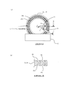
図1に本発明の放電電極2a,2bを示す。図2(a)は図1におけるA方向矢視図であり、図2(b)は図2(a)におけるB-B断面図である。また、図3は捕獲用溝部による高温プラズマ原料の捕獲を説明する図であり、図4は図2におけるC-C断面図である。なお、図3、図4には捕獲用溝部10aのみが示されている。
また、図5に図1に示す本発明の放電電極2a,2bを使用したEUV光源装置の構成例を示す。図5に示すEUV光源装置は、本発明に係る放電電極2a,2b、原料除去機構11および図10で省略した膜厚調整機構12の他は図10に示すものと同様の構成要素を有する。よって、以下で、主として本発明に係る構成要素である放電電極2a,2b、原料除去機構11および膜厚調整機構12を説明し、他の構成要素については簡単に説明する。
また、図5に図1に示す本発明の放電電極2a,2bを使用したEUV光源装置の構成例を示す。図5に示すEUV光源装置は、本発明に係る放電電極2a,2b、原料除去機構11および図10で省略した膜厚調整機構12の他は図10に示すものと同様の構成要素を有する。よって、以下で、主として本発明に係る構成要素である放電電極2a,2b、原料除去機構11および膜厚調整機構12を説明し、他の構成要素については簡単に説明する。
まず図5に示す本発明のEUV光源装置について簡単に説明する。
図5において、前記したようにチャンバ1内に放電電極2a,2bなどが収容される放電部1aと、ホイルトラップ5やEUV集光鏡6などが収容されるEUV集光部1bとが設けられ、チャンバ1内を真空状態にするためのガス排気ユニット1cが設けられる。放電電極2a,2bはそれぞれ回転モータ16a,16bが回転することにより、16c,16dを回転軸として回転する。
高温プラズマ原料14は、例えば液体状のスズ(Sn)であり、前記したようにコンテナ15に収容される。溶解金属の温度は、前記図11に示したようにコンテナ15内に設けられた温度調整手段15aにより調整される。
図5において、前記したようにチャンバ1内に放電電極2a,2bなどが収容される放電部1aと、ホイルトラップ5やEUV集光鏡6などが収容されるEUV集光部1bとが設けられ、チャンバ1内を真空状態にするためのガス排気ユニット1cが設けられる。放電電極2a,2bはそれぞれ回転モータ16a,16bが回転することにより、16c,16dを回転軸として回転する。
高温プラズマ原料14は、例えば液体状のスズ(Sn)であり、前記したようにコンテナ15に収容される。溶解金属の温度は、前記図11に示したようにコンテナ15内に設けられた温度調整手段15aにより調整される。
ここで、回転放電電極2a,2bは、レーザ光17の照射や放電で温度が上昇し、冷却をしない場合に電極表面の材料が蒸発し、変形が生じる。高温プラズマ原料を収納したコンテナ15は、この熱を電極2a,2bから除熱し、電極2a,2bの温度をコントロールする役割を持っている。このための仕組みとして、コンテナ15は温度調整手段15aを有し、コンテナ15中で電極から除熱し温度上昇した高温プラズマ原料14は、外部に取り付けられた循環機構(不図示)で循環し、経路中で高温プラズマ原料を冷却し再びコンテナ15に供給する。
上記放電電極2a,2bは、その一部が高温プラズマ原料14を収容するコンテナ15の中に浸されるように配置され、放電電極2a,2bが回転することにより、高温プラズマ原料14が放電空間に輸送されるとともに、上記の放電電極2a,2bから除熱される。また、放電空間に輸送された高温プラズマ原料14に対してレーザ源17aよりレーザ光17が照射される。レーザ光17が照射された高温プラズマ原料14は気化する。
上記放電電極2a,2bは、その一部が高温プラズマ原料14を収容するコンテナ15の中に浸されるように配置され、放電電極2a,2bが回転することにより、高温プラズマ原料14が放電空間に輸送されるとともに、上記の放電電極2a,2bから除熱される。また、放電空間に輸送された高温プラズマ原料14に対してレーザ源17aよりレーザ光17が照射される。レーザ光17が照射された高温プラズマ原料14は気化する。
高温プラズマ原料14がレーザ光17の照射により気化された状態で、放電電極2a,2bに、電力供給手段4からパルス電力が印加されることにより、両放電電極2a,2b間にパルス放電が開始し、高温プラズマ原料14によるプラズマPが形成される。放電時に流れる大電流によりプラズマが加熱励起され高温化すると、この高温プラズマPからEUVが放射される。このEUV光は、EUV集光鏡6により集光鏡6の集光点(中間集光点ともいう)fに集められ、EUV光出射口7から出射し、EUV光源装置に接続された点線で示した露光機40に入射する。
図1、図2に示すように、本発明の円盤状の放電電極2a,2bは、周縁近傍に高温プラズマ原料を捕獲するための複数の捕獲用溝部10a,10bが同心円状に設けられている。具体的には、上記した放電用溝部10a,10bは、図2に示すように、コンテナに収容されている溶融した高温プラズマ原料中を放電電極2a,2bが通過した際当該放電電極2a,2bの高温プラズマ原料が付着する領域のうち、上記した「プラズマに不要な領域」内に円輪状に設けられる。
この円輪状の捕獲用溝部10a,10bは、円盤状の放電電極2a,2bの両円形平面部に設けられる。
この円輪状の捕獲用溝部10a,10bは、円盤状の放電電極2a,2bの両円形平面部に設けられる。
このような円盤状の放電電極2a,2bを回転させる場合、従来の円盤状の放電電極2a,2bと同様、回転数(回転速度)が増加するにつれて、「プラズマに不要な領域」に付着している高温プラズマ原料14は、遠心力の作用により円盤状の放電電極2a,2bの周縁部側に移動する。
ここで、図3(a)に示すように、放電電極2a,2bの回転が低速回転の場合は、「プラズマに不要な領域」に付着している高温プラズマ原料14はほとんど移動しないが、図3(b)に示すように、放電電極2a,2bの回転が中速回転となるにつれて上記高温プラズマ原料14は円盤状の放電電極2a,2bの周縁部側に移動する。しかしながら、「プラズマに不要な領域」に付着している高温プラズマ原料14の内、捕獲用溝部10a,10bより内側(円盤状の放電電極2a,2bの中心側)に付着しているものは、捕獲用溝部10a,10bに流れ込み、捕獲用溝部10a,10bより外側(円盤状の放電電極2a,2bの周縁部側)には移動しない。
「プラズマに不要な領域」に付着している高温プラズマ原料14の内、捕獲用溝部10a,10bより外側に付着しているものは円盤状の放電電極2a,2bの周縁部側に移動する。しかし、捕獲用溝部10aより内側に付着しているものは移動してこないので、放電電極2a,2bの周縁部分における高温プラズマ原料14の膜厚はあまり増加しない。
「プラズマに不要な領域」に付着している高温プラズマ原料14の内、捕獲用溝部10a,10bより外側に付着しているものは円盤状の放電電極2a,2bの周縁部側に移動する。しかし、捕獲用溝部10aより内側に付着しているものは移動してこないので、放電電極2a,2bの周縁部分における高温プラズマ原料14の膜厚はあまり増加しない。
そして、図3(c)に示すように、放電電極2a,2bの回転が高速回転となるにつれて、「プラズマに不要な領域」に付着している高温プラズマ原料14の内、捕獲用溝部10a,10bより内側に付着しているものの捕獲用溝部10a,10bに流れ込む速度は速くなるが、捕獲用溝部10a,10bが高温プラズマ原料で満たされるまでは捕獲用溝部10a,10bより外側には移動しない。
また、放電電極2a,2bの回転が中速回転のときと同様、「プラズマに不要な領域」に付着している高温プラズマ原料14の内、捕獲用溝部10a,10bより外側に付着しているものは円盤状の放電電極2a,2bの周縁部側に移動する。しかし、捕獲用溝部10aより内側に付着しているものは移動してこないので、放電電極2a,2bの周縁部分における高温プラズマ原料14の膜厚はあまり増加しない。
また、放電電極2a,2bの回転が中速回転のときと同様、「プラズマに不要な領域」に付着している高温プラズマ原料14の内、捕獲用溝部10a,10bより外側に付着しているものは円盤状の放電電極2a,2bの周縁部側に移動する。しかし、捕獲用溝部10aより内側に付着しているものは移動してこないので、放電電極2a,2bの周縁部分における高温プラズマ原料14の膜厚はあまり増加しない。
以上のように、本発明の極端紫外光光源装置の円盤状の放電電極2a,2bは、その一部がコンテナ15に収容された溶解した高温プラズマ原料14に浸漬していて、回転動作により高温プラズマ原料14が付着した部分を放電部に当該高温プラズマ原料を輸送する構造であって、円盤状の放電電極2a,2bの円形表面に付着している円環状の領域の一部に同心円状に円環状の捕獲用溝部10a,10bを設けたものである。
よって、比較的高速に上記放電電極2a,2bを回転したとしても、捕獲用溝部10a,10bより内側(円盤状の放電電極2a,2bの中心側)に付着している高温プラズマ原料14は捕獲用溝部10a,10bに流れ込み、捕獲用溝部10a,10bより外側(円盤状の放電電極2a,2bの周縁部側)には移動しない。
そのため、従来のように回転する放電電極2a,2bのように、放電電極2a,2bの周縁部側に移動する高温プラズマ原料14の量が減少し、放電電極2a,2bの周縁部分における高温プラズマ原料14の膜厚の増加が顕著に小さくなり、電極2a,2b表面を離脱する高温プラズマ原料14の液滴の形成が抑制される。
従って、放電電極2a,2bから飛散する高温プラズマ原料14によるチャンバ内壁やチャンバ内に設置された各構成要素の汚染も小さくすることが可能となる。
なお、前記図10で省略した膜厚調整機構12は、図4に示すように、放電電極2a,2bにおけるプラズマに必要な膜領域における高温プラズマ原料の厚みを最適厚みにするためのものである。すなわち、レーザビームが照射される円盤状の放電電極2a,2bの曲面部上方の空間の大きさを規制して、上記曲面部に付着する高温プラズマ原料の膜厚を最適厚みに調整する
図3に戻り、同図における捕獲用溝部10aの側壁部の角度は放電電極2a,2bの円形平面を基準平面としたとき当該平面に対して負の角度を成しているが、これに限るものではなく放電電極2a,2bの円形平面に対して直角であってもよい。しかし上記側壁部の角度が円形平面に対して負の角度を成している場合、捕獲用溝部10a,10bより内側に付着している高温プラズマ原料が上記捕獲用溝部10a,10bに流れ込みやすく、一旦捕獲用溝部10a,10bに流れ込んだ高温プラズマ原料が外部に流出しにくいという利点を有する。よって、獲用溝部10aの側壁部の角度は放電電極2a,2bの円形平面を基準平面としたとき当該平面に対して負の角度を成している方が好ましい。
図1、図2等に示したように、本発明においては円環状の捕獲用溝部10a,10bを1つの円形表面に二箇所同心円状に設けたが、このように捕獲用溝部を放電電極2a,2bに複数、同心円状に設けることで、円環状の捕獲用溝部を当該円形平面に1つ設ける場合と比較すると、円盤状の放電電極2a,2bの円形平面側に付着した高温プラズマ原料の捕獲可能体積を大きくすることが可能となる。このため、放電電極2a,2bの高速回転時における放電電極2a,2bから飛散する高温プラズマ原料によるチャンバ内壁やチャンバ内に設置された各構成要素の汚染を更に小さくすることが可能となる。
また、捕獲用溝部を複数設けることで、一つ当たりの捕獲用溝部の容積を小さくすることができ、捕獲用溝部の深さを浅くすることが可能となる。このため、捕獲用溝部を設けることによる放電電極の強度の低下を抑制しながら、「プラズマの発生に不要な領域」に付着している高温プラズマ原料を充分にかつ確実に捕獲することが可能となる。
また、捕獲用溝部を複数設けることで、一つ当たりの捕獲用溝部の容積を小さくすることができ、捕獲用溝部の深さを浅くすることが可能となる。このため、捕獲用溝部を設けることによる放電電極の強度の低下を抑制しながら、「プラズマの発生に不要な領域」に付着している高温プラズマ原料を充分にかつ確実に捕獲することが可能となる。
図1、図2等では、円環状の捕獲用溝部10a,10bを1つの円形表面に二箇所同心円状に設けた例を示したが、図6に示すように、円環状の捕獲用溝部10a,10b,10cを1つの円形表面に三箇所同心円状に設けてもよい。なお、図6において、同図(a)は前記図1におけるA方向矢視図であり、同図(b)は同図(a)におけるB-B断面図である。
また、複数の捕獲用溝部の深さは、必ずしも全て同じ深さでなくてもよい。例えば、図7(a)(b)に示すように、放電電極2a,2bの周縁部方向に向かうに従って浅くなるように設定してもよい。図7(a)に示す例では、捕獲用溝部10a,10bが各平面に二箇所設けられていて、放電電極2a,2bの最も周縁部側に位置する放電用溝部10aの深さD1は、その隣の放電用溝部10bの深さD2より浅い。
また、各捕獲用溝部に捕獲される高温プラズマ原料の量は、円盤状の放電電極2a,2bの円形平面部に高温プラズマ原料が付着した領域であって、各捕獲用溝部10aに隣接する平面部のうち、上記円形平面の中心側に隣接する領域の面積にほぼ比例するものと考えられる。そして、概略的には、上記隣接する平面部の放射方向の長さにほぼ比例すると考えられる。
また、各捕獲用溝部に捕獲される高温プラズマ原料の量は、円盤状の放電電極2a,2bの円形平面部に高温プラズマ原料が付着した領域であって、各捕獲用溝部10aに隣接する平面部のうち、上記円形平面の中心側に隣接する領域の面積にほぼ比例するものと考えられる。そして、概略的には、上記隣接する平面部の放射方向の長さにほぼ比例すると考えられる。
よって、例えば放電用溝部10aの上記円形平面の中心側に隣接する領域の放射方向の長さをL1、放電用溝部10bの上記円形平面の中心側に隣接する領域の放射方向の長さをL2とするとき、D1:D2=L1:L2もしくはD1:D2≒L1:L2となるように、上記放電用溝部10a,10bの深さD1、D2を設定してもよい。
また、図7(b)は捕獲用溝部が各平面に三箇所設けられている例では、捕獲用溝部10a,10b,10cが各平面に三箇所設けられていて、放電電極2a,2bの最も周縁部側に位置する放電用溝部10aの深さD1はその隣の放電用溝部10bの深さD2より浅く、上記深さD2は、放電用溝部10bの隣の放電用溝部10cの深さD3より浅くなっている。そして、放電用溝部10aの上記円形平面の中心側に隣接する領域の放射方向の長さをL1、放電用溝部10bの上記円形平面の中心側に隣接する領域の放射方向の長さをL2、放電用溝部10cの上記円形平面の中心側に隣接する領域の放射方向の長さをL3とするとき、D1:D2:D3=L1:L2:L3もしくはD1:D2:D3≒L1:L2:L3となるように、上記放電用溝部10aの深さD1、D2、D3を設定してもよい。
なお、図7に示す例では、複数の捕獲用溝部10aの深さの少なくとも1つが異なる例を示したがこれに限るものではない。例えば、複数の捕獲用溝部10aの深さが同じで、幅の少なくとも1つが異なるように構成してもよい。
なお、捕獲用溝部を複数設ける代わりに、図8に示すように、放電電極2a,2bの周辺部に突起部13を設け、ここに、捕獲用凹部13aを多段構造で設けても同様の効果が得られるものと考えられる。しかしながら多段構造は以下の理由により好ましくない。すなわち、放電電極2a,2bは、5mm程度の厚みで高速に回転している。よって、図8に示すように多段構造を採用して放電電極の中心付近を薄くすると、回転初期に放電電極2a,2bの回転軸付近の材料に負荷が生じ、電極の変形および破損が生じると考えられ望ましくない。
ところで、EUV光源装置の動作時間の経過につれて、円盤状の放電電極2a,2bに設けた捕獲用溝部10a,10b,…,に流入する高温プラズマ原料の流入量も大きくなる。そして、上記流入量が上記捕獲用溝部10a,10b,…,の捕獲可能容量を超えると、円盤状の放電電極2a,2bの周縁部側に移動する高温プラズマ原料の量が大きくなり、放電電極2a,2bの周縁部分における高温プラズマ原料の膜厚が増加し、電極2a,2b表面を離脱する高温プラズマ原料の液滴の形成頻度が大きくなる。そこで、定期的に捕獲用溝部10aに流入した高温プラズマ原料を除去することが望ましい。
そのために、例えば図1、図5、図9に示すように、捕獲用溝部10a,10bに流入した高温プラズマ原料を除去する原料除去機構11を設けてもよい。
同図に示すように、原料除去機構11は、2組の円盤状の放電電極2a,2bの各円形平面に形成された各捕獲用溝部毎に合計4組設けられ、例えば捕獲用溝部が同心円状に2箇所に設けられている場合は8組設けられる。
図9に示すように、原料除去機構11は、棒状の形状であって先端が捕獲用溝部10aに進入・退避が可能な形状となっている。
図9(a)に示すように、捕獲用溝部10aに流入した高温プラズマ原料の量が増加すると、原料除去機構11は捕獲用溝部10aに挿入される方向に進行する。そして、図9(b)に示すように、原料除去機構11の先端は捕獲用溝部10aに挿入される。このとき放電電極2a,2bは回転しているので、捕獲用溝部10aに流入していた高温プラズマ原料は、原料除去機構11と接触しながら徐々に外部に掻き出される。
捕獲用溝部10aに流入していた高温プラズマ原料の量の殆どを外部に掻き出したあと、原料除去機構11は捕獲用溝部10aから退避する方向に進行する。
なお、原料除去機構11から掻き出された高温プラズマ原料は重力方向に落下するが、落下してくる高温プラズマ原料を収容する原料収容部を適宜設けることが望ましい。例えば、図5に示すように、溶融した高温プラズマ原料を収容するコンテナを図10と比較して大きくして、落下してくる高温プラズマ原料を収容可能なように構成してもよい。
1 チャンバ
1a 放電部
1b EUV集光部
1c ガス排気ユニット
2a,2b 放電電極
4 電力供給手段
5 ホイルトラップ
6 EUV集光鏡
10a,10b,10c 捕獲用溝部
11 原料除去機構
12 膜厚調整機構
14 高温プラズマ原料
15 コンテナ
15a 温度調整手段
16a,16b 回転モータ
16c,16d 回転軸
17 レーザ光
17a レーザ源
40 露光機
P 高温プラズマ
1a 放電部
1b EUV集光部
1c ガス排気ユニット
2a,2b 放電電極
4 電力供給手段
5 ホイルトラップ
6 EUV集光鏡
10a,10b,10c 捕獲用溝部
11 原料除去機構
12 膜厚調整機構
14 高温プラズマ原料
15 コンテナ
15a 温度調整手段
16a,16b 回転モータ
16c,16d 回転軸
17 レーザ光
17a レーザ源
40 露光機
P 高温プラズマ
Claims (5)
- 互いに離間して配置される一対の円盤状の放電電極と、上記放電電極にパルス電力を供給するパルス電力供給手段と、光を放射させるための原料を前記放電電極上に供給する原料供給手段と、上記放電電極の曲面上の原料にエネルギービームを照射して当該原料を気化するエネルギービーム照射手段とを有し、上記原料供給手段は、上記原料の融液を充填した容器を備え、上記各放電電極が回転し、当該各放電電極の一部が前記容器内に充填された原料融液を通過することにより、上記各放電電極の一部に上記原料が付着するように構成された光源装置における放電電極であって、
上記各放電電極の2つの円形表面の、上記原料が付着する円環状の領域の一部に、複数の円環状の捕獲用溝部が同心円状に設けられていることを特徴とする放電電極。 - 棒状の形状であって先端が上記捕獲用溝部に進入・退避が可能な原料除去機構が設けられていることを特徴とする請求項1に記載の放電電極。
- 上記複数の捕獲用溝部のうち、少なくとも1つの捕獲用溝部の深さが他の捕獲用溝部の深さと相違することを特徴とする請求項1または請求項2に記載の放電電極。
- 上記各捕獲用溝部の深さの比は、円盤状の放電電極の円形平面部に高温プラズマ原料が付着した領域であって、各捕獲用溝部に隣接する平面部のうち、上記円形平面の中心側に隣接する平面部の放射方向の長さの比に等しいか、ほぼ等しいように設定されている
ことを特徴とする請求項3に記載の放電電極。 - 上記捕獲用溝部の側壁部の角度が、放電電極の円形平面を基準平面としたとき当該平面に対して負の角度を成していることを特徴とする請求項1、2、3または請求項4のいずれか1項に記載の放電電極。
Priority Applications (1)
| Application Number | Priority Date | Filing Date | Title |
|---|---|---|---|
| US14/437,652 US9433068B2 (en) | 2012-10-30 | 2013-10-22 | Discharge electrodes for use in a light source device |
Applications Claiming Priority (2)
| Application Number | Priority Date | Filing Date | Title |
|---|---|---|---|
| JP2012239007A JP5724986B2 (ja) | 2012-10-30 | 2012-10-30 | 放電電極 |
| JP2012-239007 | 2012-10-30 |
Publications (1)
| Publication Number | Publication Date |
|---|---|
| WO2014069283A1 true WO2014069283A1 (ja) | 2014-05-08 |
Family
ID=50627194
Family Applications (1)
| Application Number | Title | Priority Date | Filing Date |
|---|---|---|---|
| PCT/JP2013/078556 WO2014069283A1 (ja) | 2012-10-30 | 2013-10-22 | 放電電極 |
Country Status (3)
| Country | Link |
|---|---|
| US (1) | US9433068B2 (ja) |
| JP (1) | JP5724986B2 (ja) |
| WO (1) | WO2014069283A1 (ja) |
Families Citing this family (6)
| Publication number | Priority date | Publication date | Assignee | Title |
|---|---|---|---|---|
| JP6477179B2 (ja) * | 2015-04-07 | 2019-03-06 | ウシオ電機株式会社 | 放電電極及び極端紫外光光源装置 |
| JP6237825B2 (ja) * | 2016-05-27 | 2017-11-29 | ウシオ電機株式会社 | 高温プラズマ原料供給装置および極端紫外光光源装置 |
| RU2670273C2 (ru) * | 2017-11-24 | 2018-10-22 | Общество с ограниченной ответственностью "РнД-ИСАН" | Устройство и способ для генерации излучения из лазерной плазмы |
| JP7405000B2 (ja) * | 2020-05-15 | 2023-12-26 | ウシオ電機株式会社 | 極端紫外光光源装置および極端紫外光の生成方法 |
| JP2023149176A (ja) * | 2022-03-30 | 2023-10-13 | ウシオ電機株式会社 | 光源装置 |
| JP2024059178A (ja) * | 2022-10-18 | 2024-05-01 | ウシオ電機株式会社 | 光源装置及び原料供給ユニット |
Citations (4)
| Publication number | Priority date | Publication date | Assignee | Title |
|---|---|---|---|---|
| JP2009224182A (ja) * | 2008-03-17 | 2009-10-01 | Ushio Inc | 極端紫外光光源装置 |
| JP2010061903A (ja) * | 2008-09-02 | 2010-03-18 | Ushio Inc | 極端紫外光光源装置および極端紫外光光源装置の残留ガス除去方法 |
| JP2010153563A (ja) * | 2008-12-25 | 2010-07-08 | Ushio Inc | 極端紫外光光源装置 |
| JP2010539637A (ja) * | 2007-09-07 | 2010-12-16 | コーニンクレッカ フィリップス エレクトロニクス エヌ ヴィ | ガス放電光源用の電極デバイス、及びこの電極デバイスをもつガス放電光源を作動させる方法 |
Family Cites Families (2)
| Publication number | Priority date | Publication date | Assignee | Title |
|---|---|---|---|---|
| DE10342239B4 (de) | 2003-09-11 | 2018-06-07 | Fraunhofer-Gesellschaft zur Förderung der angewandten Forschung e.V. | Verfahren und Vorrichtung zum Erzeugen von Extrem-Ultraviolettstrahlung oder weicher Röntgenstrahlung |
| DE102006015641B4 (de) * | 2006-03-31 | 2017-02-23 | Ushio Denki Kabushiki Kaisha | Vorrichtung zur Erzeugung von extrem ultravioletter Strahlung mittels einer elektrisch betriebenen Gasentladung |
-
2012
- 2012-10-30 JP JP2012239007A patent/JP5724986B2/ja active Active
-
2013
- 2013-10-22 WO PCT/JP2013/078556 patent/WO2014069283A1/ja active Application Filing
- 2013-10-22 US US14/437,652 patent/US9433068B2/en active Active
Patent Citations (4)
| Publication number | Priority date | Publication date | Assignee | Title |
|---|---|---|---|---|
| JP2010539637A (ja) * | 2007-09-07 | 2010-12-16 | コーニンクレッカ フィリップス エレクトロニクス エヌ ヴィ | ガス放電光源用の電極デバイス、及びこの電極デバイスをもつガス放電光源を作動させる方法 |
| JP2009224182A (ja) * | 2008-03-17 | 2009-10-01 | Ushio Inc | 極端紫外光光源装置 |
| JP2010061903A (ja) * | 2008-09-02 | 2010-03-18 | Ushio Inc | 極端紫外光光源装置および極端紫外光光源装置の残留ガス除去方法 |
| JP2010153563A (ja) * | 2008-12-25 | 2010-07-08 | Ushio Inc | 極端紫外光光源装置 |
Also Published As
| Publication number | Publication date |
|---|---|
| US20150282285A1 (en) | 2015-10-01 |
| US9433068B2 (en) | 2016-08-30 |
| JP5724986B2 (ja) | 2015-05-27 |
| JP2014089880A (ja) | 2014-05-15 |
Similar Documents
| Publication | Publication Date | Title |
|---|---|---|
| WO2014069283A1 (ja) | 放電電極 | |
| JP6241062B2 (ja) | 極端紫外光光源装置 | |
| KR102597847B1 (ko) | 고휘도 lpp 소스 및 방사선 생성과 잔해 완화를 위한 방법 | |
| US10381216B2 (en) | Continuous-wave laser-sustained plasma illumination source | |
| KR20080011048A (ko) | 극단 자외광 광원 장치 및 극단 자외광 발생 방법 | |
| JP2007200919A (ja) | 極端紫外光光源装置 | |
| JP2008108599A (ja) | 極端紫外光光源装置 | |
| WO2015098031A1 (ja) | 光源装置 | |
| JP6176138B2 (ja) | デブリ低減装置 | |
| JP4952513B2 (ja) | 極端紫外光光源装置 | |
| JP2007103176A (ja) | 放射線源用ターゲット生成供給装置 | |
| KR20100093609A (ko) | 특히 euv 방사선용의 가스 방전 소스 | |
| JP2009104924A (ja) | 極端紫外光光源装置 | |
| JP2016201178A (ja) | 放電電極及び極端紫外光光源装置 | |
| JP2014154271A (ja) | ホイルトラップおよびこのホイルトラップを用いた光源装置 | |
| JP2007305908A (ja) | 極端紫外光光源装置 | |
| JP2009224182A (ja) | 極端紫外光光源装置 | |
| JP2000298200A (ja) | レーザー励起型x線源 | |
| JP4973425B2 (ja) | 極端紫外光光源装置における集光光学手段のクリーニング方法及び極端紫外光光源装置 | |
| JP2009049151A (ja) | レーザプラズマ光源 | |
| US11822258B2 (en) | Foil trap and light source apparatus including the same | |
| JP2023033671A (ja) | 放電プラズマ生成ユニット、及びそれを搭載した光源装置 | |
| WO2023228629A1 (ja) | 光源装置 | |
| WO2024004381A1 (ja) | デブリ低減装置及びこれを備えた光源装置 | |
| JP2010061903A (ja) | 極端紫外光光源装置および極端紫外光光源装置の残留ガス除去方法 |
Legal Events
| Date | Code | Title | Description |
|---|---|---|---|
| 121 | Ep: the epo has been informed by wipo that ep was designated in this application |
Ref document number: 13850299 Country of ref document: EP Kind code of ref document: A1 |
|
| WWE | Wipo information: entry into national phase |
Ref document number: 14437652 Country of ref document: US |
|
| NENP | Non-entry into the national phase |
Ref country code: DE |
|
| 122 | Ep: pct application non-entry in european phase |
Ref document number: 13850299 Country of ref document: EP Kind code of ref document: A1 |