WO2014065406A1 - 超音波プローブ - Google Patents
超音波プローブ Download PDFInfo
- Publication number
- WO2014065406A1 WO2014065406A1 PCT/JP2013/078991 JP2013078991W WO2014065406A1 WO 2014065406 A1 WO2014065406 A1 WO 2014065406A1 JP 2013078991 W JP2013078991 W JP 2013078991W WO 2014065406 A1 WO2014065406 A1 WO 2014065406A1
- Authority
- WO
- WIPO (PCT)
- Prior art keywords
- cross
- longitudinal axis
- sectional shape
- groove
- unit
- Prior art date
Links
Images


Classifications
-
- A—HUMAN NECESSITIES
- A61—MEDICAL OR VETERINARY SCIENCE; HYGIENE
- A61B—DIAGNOSIS; SURGERY; IDENTIFICATION
- A61B17/00—Surgical instruments, devices or methods, e.g. tourniquets
- A61B17/32—Surgical cutting instruments
- A61B17/320068—Surgical cutting instruments using mechanical vibrations, e.g. ultrasonic
-
- A—HUMAN NECESSITIES
- A61—MEDICAL OR VETERINARY SCIENCE; HYGIENE
- A61B—DIAGNOSIS; SURGERY; IDENTIFICATION
- A61B8/00—Diagnosis using ultrasonic, sonic or infrasonic waves
- A61B8/44—Constructional features of the ultrasonic, sonic or infrasonic diagnostic device
- A61B8/4444—Constructional features of the ultrasonic, sonic or infrasonic diagnostic device related to the probe
-
- A—HUMAN NECESSITIES
- A61—MEDICAL OR VETERINARY SCIENCE; HYGIENE
- A61B—DIAGNOSIS; SURGERY; IDENTIFICATION
- A61B18/00—Surgical instruments, devices or methods for transferring non-mechanical forms of energy to or from the body
- A61B18/04—Surgical instruments, devices or methods for transferring non-mechanical forms of energy to or from the body by heating
- A61B18/12—Surgical instruments, devices or methods for transferring non-mechanical forms of energy to or from the body by heating by passing a current through the tissue to be heated, e.g. high-frequency current
- A61B18/14—Probes or electrodes therefor
- A61B18/1442—Probes having pivoting end effectors, e.g. forceps
- A61B18/1445—Probes having pivoting end effectors, e.g. forceps at the distal end of a shaft, e.g. forceps or scissors at the end of a rigid rod
-
- A—HUMAN NECESSITIES
- A61—MEDICAL OR VETERINARY SCIENCE; HYGIENE
- A61B—DIAGNOSIS; SURGERY; IDENTIFICATION
- A61B17/00—Surgical instruments, devices or methods, e.g. tourniquets
- A61B2017/00477—Coupling
-
- A—HUMAN NECESSITIES
- A61—MEDICAL OR VETERINARY SCIENCE; HYGIENE
- A61B—DIAGNOSIS; SURGERY; IDENTIFICATION
- A61B17/00—Surgical instruments, devices or methods, e.g. tourniquets
- A61B17/32—Surgical cutting instruments
- A61B17/320068—Surgical cutting instruments using mechanical vibrations, e.g. ultrasonic
- A61B2017/320069—Surgical cutting instruments using mechanical vibrations, e.g. ultrasonic for ablating tissue
-
- A—HUMAN NECESSITIES
- A61—MEDICAL OR VETERINARY SCIENCE; HYGIENE
- A61B—DIAGNOSIS; SURGERY; IDENTIFICATION
- A61B17/00—Surgical instruments, devices or methods, e.g. tourniquets
- A61B17/32—Surgical cutting instruments
- A61B17/320068—Surgical cutting instruments using mechanical vibrations, e.g. ultrasonic
- A61B2017/32007—Surgical cutting instruments using mechanical vibrations, e.g. ultrasonic with suction or vacuum means
-
- A—HUMAN NECESSITIES
- A61—MEDICAL OR VETERINARY SCIENCE; HYGIENE
- A61B—DIAGNOSIS; SURGERY; IDENTIFICATION
- A61B17/00—Surgical instruments, devices or methods, e.g. tourniquets
- A61B17/32—Surgical cutting instruments
- A61B17/320068—Surgical cutting instruments using mechanical vibrations, e.g. ultrasonic
- A61B2017/320089—Surgical cutting instruments using mechanical vibrations, e.g. ultrasonic node location
-
- A—HUMAN NECESSITIES
- A61—MEDICAL OR VETERINARY SCIENCE; HYGIENE
- A61B—DIAGNOSIS; SURGERY; IDENTIFICATION
- A61B17/00—Surgical instruments, devices or methods, e.g. tourniquets
- A61B17/32—Surgical cutting instruments
- A61B17/320068—Surgical cutting instruments using mechanical vibrations, e.g. ultrasonic
- A61B17/320092—Surgical cutting instruments using mechanical vibrations, e.g. ultrasonic with additional movable means for clamping or cutting tissue, e.g. with a pivoting jaw
- A61B2017/320095—Surgical cutting instruments using mechanical vibrations, e.g. ultrasonic with additional movable means for clamping or cutting tissue, e.g. with a pivoting jaw with sealing or cauterizing means
-
- A—HUMAN NECESSITIES
- A61—MEDICAL OR VETERINARY SCIENCE; HYGIENE
- A61B—DIAGNOSIS; SURGERY; IDENTIFICATION
- A61B2218/00—Details of surgical instruments, devices or methods for transferring non-mechanical forms of energy to or from the body
- A61B2218/001—Details of surgical instruments, devices or methods for transferring non-mechanical forms of energy to or from the body having means for irrigation and/or aspiration of substances to and/or from the surgical site
- A61B2218/002—Irrigation
-
- A—HUMAN NECESSITIES
- A61—MEDICAL OR VETERINARY SCIENCE; HYGIENE
- A61B—DIAGNOSIS; SURGERY; IDENTIFICATION
- A61B2218/00—Details of surgical instruments, devices or methods for transferring non-mechanical forms of energy to or from the body
- A61B2218/001—Details of surgical instruments, devices or methods for transferring non-mechanical forms of energy to or from the body having means for irrigation and/or aspiration of substances to and/or from the surgical site
- A61B2218/007—Aspiration
-
- A—HUMAN NECESSITIES
- A61—MEDICAL OR VETERINARY SCIENCE; HYGIENE
- A61B—DIAGNOSIS; SURGERY; IDENTIFICATION
- A61B2560/00—Constructional details of operational features of apparatus; Accessories for medical measuring apparatus
- A61B2560/04—Constructional details of apparatus
Definitions
- the present invention relates to an ultrasonic probe used in an ultrasonic treatment apparatus such as an ultrasonic suction apparatus.
- Patent Document 1 discloses an ultrasonic treatment apparatus that performs ultrasonic suction as one of the treatments.
- This ultrasonic treatment apparatus includes an ultrasonic probe that transmits ultrasonic vibration from a proximal direction to a distal direction.
- the ultrasonic suction is performed using the tip surface of the ultrasonic probe that is ultrasonically vibrated, and is performed using a physical phenomenon called cavitation.
- cavitation a physical phenomenon that is ultrasonic probe repeats tens of thousands of high-speed vibrations per second due to the ultrasonic vibration, the pressure periodically fluctuates in the vicinity of the tip surface of the ultrasonic probe.
- a minute bubble in the liquid in the body cavity or the liquid sent from the ultrasonic treatment device to the vicinity of the treatment position of the living tissue) Cavity
- the generated bubbles disappear due to the force acting when the pressure in the vicinity of the front end surface increases (compresses).
- Such a physical phenomenon is called a cavitation phenomenon.
- the non-elastic biological tissue such as hepatocytes is shattered and emulsified.
- a suction passage extends from the proximal end to the distal end.
- the crushed and emulsified biological tissue is sucked and collected from the suction port at the tip of the ultrasonic probe through the suction passage.
- a living tissue is excised by continuing the above actions.
- a highly elastic living tissue such as a blood vessel is hardly crushed because the impact is absorbed, and the living tissue is selectively crushed.
- the suction passage penetrates from the proximal end to the distal end (that is, over the entire length in the direction parallel to the longitudinal axis), the ultrasonic probe is formed in a cylindrical shape.
- Patent Document 2 also discloses an ultrasonic probe that transmits ultrasonic vibrations from the proximal direction to the distal direction.
- This ultrasonic probe has a groove-like portion that is recessed toward a first vertical direction perpendicular to the longitudinal axis (axial parallel direction) and that opens toward a second vertical direction that is opposite to the first vertical direction.
- a formed probe main body is provided. Forming the groove-like portion in the probe main body portion is performed in a short time and at a low cost as compared with drilling a columnar member. For this reason, the ultrasonic probe provided with the probe main body part in which the groove-like part is formed has improved work efficiency at the time of manufacture compared to the ultrasonic probe formed in a cylindrical shape over the entire length in the axial parallel direction. In addition, the manufacturing cost is reduced.
- the cylindrical ultrasonic probe used in the ultrasonic treatment apparatus of Patent Document 1 is formed by drilling a columnar member.
- the columnar member that is the material of the ultrasonic probe has a long dimension along the longitudinal axis and a small dimension in a direction perpendicular to the longitudinal axis.
- Such a long and narrow columnar member is drilled for a long time using a dedicated drill. Therefore, the work efficiency at the time of manufacturing the ultrasonic probe is reduced, and the manufacturing cost of the ultrasonic probe is increased.
- the probe main body having the groove-like portion since the probe main body having the groove-like portion is provided, the working efficiency at the time of manufacturing the ultrasonic probe is improved, and the manufacturing cost is reduced.
- the cross-sectional shape perpendicular to the longitudinal axis is asymmetric with respect to the longitudinal axis.
- a cross-sectional area changing portion in which a cross-sectional area perpendicular to the longitudinal axis is changed is provided to increase the amplitude of the ultrasonic vibration.
- the center of gravity of the ultrasonic probe with the longitudinal axis in the cross section perpendicular to the longitudinal axis as the reference position The position is shifted at the cross-sectional area changing portion. That is, the position of the center of gravity of the ultrasonic probe when the longitudinal axis in the cross section perpendicular to the longitudinal axis is the reference position does not match between the proximal direction side of the cross-sectional area changing portion and the distal direction side of the cross-sectional area changing portion.
- the center of gravity position of the ultrasonic probe when the longitudinal axis in the cross section perpendicular to the longitudinal axis is set as the reference position is shifted at the cross-sectional area changing portion, thereby reducing the transmission of ultrasonic vibration and the strength of the ultrasonic probe. Will fall.
- the present invention has been made paying attention to the above-mentioned problems, and its object is to provide a cross-sectional area changing portion that can be manufactured efficiently and at low cost, and whose cross-sectional area perpendicular to the longitudinal axis changes. It is an object of the present invention to provide an ultrasonic probe that can ensure the transmission and strength of ultrasonic vibration even in the case of the occurrence of a problem.
- an aspect of the present invention is an ultrasonic probe capable of transmitting ultrasonic vibration along a longitudinal axis from a proximal direction to a distal direction, wherein the longitudinal probe is exposed to the outside.
- a transmission unit having a unit outer surface provided along an axis, wherein a cross-sectional shape perpendicular to the longitudinal axis is asymmetric with respect to the longitudinal axis, and the longitudinal direction of the transmission unit is perpendicular to the longitudinal axis.
- a groove-shaped portion that is recessed from the outer surface of the unit toward a first vertical direction perpendicular to the axis and opens to the outside in a second vertical direction that is opposite to the first vertical direction.
- an ultrasonic wave that can be manufactured efficiently and at low cost, and is capable of ensuring the transmission and strength of ultrasonic vibration even when a cross-sectional area changing portion whose cross-sectional area is perpendicular to the longitudinal axis is provided.
- a probe can be provided.
- FIG. 1 is a schematic view showing an ultrasonic treatment apparatus according to a first embodiment of the present invention.
- FIG. 3 is a cross-sectional view schematically illustrating a configuration of a vibrator unit according to the first embodiment.
- 1 is a perspective view schematically showing an ultrasonic probe according to a first embodiment. It is a perspective view showing the ultrasonic probe concerning a 1st embodiment roughly disassembled for every member.
- 1 is a cross-sectional view schematically showing an ultrasonic probe according to a first embodiment. It is sectional drawing which shows roughly the structure of the sheath and ultrasonic probe which concern on 1st Embodiment. It is a perspective view which shows roughly the structure of the probe main-body part of the ultrasonic probe which concerns on 1st Embodiment.
- FIG. 9 is a sectional view taken along line IX-IX in FIG. 8.
- FIG. 9 is a sectional view taken along line XX in FIG. 8.
- FIG. 11 is a cross-sectional view taken along line 11-11 in FIG. 6.
- FIG. 19 is a cross-sectional view taken along line 19-19 of FIG.
- FIG. 20 is a sectional view taken along line 20-20 in FIG.
- FIG. 34 is a cross-sectional view taken along line 34-34 of FIG.
- FIG. 35 is a sectional view taken along line 35-35 in FIG. 33. It is a perspective view which shows roughly one transmission unit structure with the probe main-body part which concerns on an 11th modification.
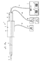
- FIG. 1 is a diagram showing an ultrasonic treatment apparatus 1 of the present embodiment.
- the ultrasonic treatment apparatus 1 of this embodiment is an ultrasonic suction apparatus that selectively crushes and excises living tissue by cavitation generated by ultrasonic vibration and sucks the excised living tissue.
- treatment using a high frequency current is also performed. Therefore, the ultrasonic treatment apparatus 1 is an energy treatment apparatus that performs treatment of a living tissue that is a treatment target using energy such as ultrasonic vibration and high-frequency current.
- the ultrasonic treatment apparatus 1 has a longitudinal axis C.
- one of the directions parallel to the longitudinal axis C (the direction of the arrow C1 in FIG. 1) is the distal direction
- the other of the directions parallel to the longitudinal axis C (the direction of the arrow C2 in FIG. 1) is the proximal direction. is there.
- the distal end direction and the proximal end direction are parallel to the longitudinal axis C.
- the ultrasonic treatment device 1 includes a transducer unit 2, an ultrasonic probe (probe unit) 3, a sheath (sheath unit) 4, and a holding unit 5.
- the vibrator unit 2 includes a vibrator case 11. One end of the cable 6 is connected to the base end of the vibrator case 11. The other end of the cable 6 is connected to the power supply unit 7.
- the power supply unit 7 includes an ultrasonic control unit 8 and a high frequency control unit 9.
- An input unit 10 such as a foot switch is connected to the power supply unit 7.
- FIG. 2 is a diagram showing the configuration of the vibrator unit 2.
- a horn member 12 is provided inside the vibrator case 11.
- the horn member 12 is attached to the vibrator case 11.
- An ultrasonic vibrator 13 including piezoelectric elements 15A to 15C that convert current into ultrasonic vibration is attached to the horn member 12.
- One end of electric signal lines 16A and 16B is connected to the ultrasonic transducer 13.
- the electric signal lines 16 ⁇ / b> A and 16 ⁇ / b> B pass through the inside of the cable 6, and the other end is connected to the ultrasonic control unit 8 of the power supply unit 7.
- the horn member 12 is provided with a cross-sectional area changing portion (horn portion) 18 that expands the amplitude of the ultrasonic vibration.
- the cross-sectional area changing portion 18 is located on the distal direction side with respect to the ultrasonic transducer 13.
- the horn member 12 is formed with a cavity 21 around the longitudinal axis C.
- the cavity 21 extends along the longitudinal axis C from the proximal end to the distal end of the horn member 12.
- a female screw portion 22 is formed at the tip of the inner peripheral surface of the horn member 12.
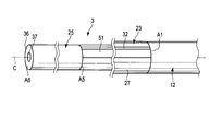
- the ultrasonic probe 3 includes a proximal probe member 23 and a distal probe member 25.
- the proximal-side probe member 23 includes a probe main body 27 that extends along the longitudinal axis C.
- the base end side connection portion 28 is continuous with the base end direction side of the probe main body 27.
- the proximal end side connection portion 28 is formed in a cylindrical shape, and the cross-sectional shape perpendicular to the longitudinal axis C of the proximal end side connection portion 28 is a point-symmetrical shape about the longitudinal axis C. Therefore, the position of the center of gravity of the proximal end side connection portion 28 is located on the longitudinal axis C in the cross section perpendicular to the longitudinal axis C.
- a male screw portion 29 is formed on the outer peripheral portion of the base end side connection portion 28.
- the proximal probe member 23 When the male screw portion 29 is screwed with the female screw portion 22 of the horn member 12, the proximal probe member 23 is connected to the distal direction side of the horn member 12. In a state where the proximal end side probe member 23 is connected to the horn member 12, the proximal end side connection portion 28 is located inside the horn member 12 (hollow portion 21).
- a groove-shaped portion 32 is defined along the longitudinal axis C by a groove defining portion 31 in the probe main body portion 27.
- the groove-like portion 32 extends from the proximal end to the distal end of the probe main body portion 27. That is, the groove-like portion 32 is provided over the entire length of the probe main body portion 27 in the axis parallel direction that is a direction parallel to the longitudinal axis C.
- the groove portion 32 is recessed in a first vertical direction (in the direction of the arrow X1 in FIG. 5) perpendicular to the longitudinal axis C.
- the groove-like portion 32 opens toward the second vertical direction (the direction of the arrow X2 in FIG. 5), which is the direction opposite to the first vertical direction.
- the distal end side connecting portion 33 is continuous with the distal end side of the probe main body 27.
- the distal end side connection portion 33 is formed in a cylindrical shape, and a cross-sectional shape perpendicular to the longitudinal axis C of the distal end side connection portion 33 is a point-symmetric shape with respect to the longitudinal axis C. Therefore, the gravity center position of the distal end side connecting portion 33 is located on the longitudinal axis C in the cross section perpendicular to the longitudinal axis C.
- a male screw portion 35 is formed on the outer peripheral portion of the distal end side connecting portion 33.
- the distal-side probe member 25 is formed in a cylindrical shape, and a cross-sectional shape perpendicular to the longitudinal axis C of the distal-side probe member 25 is a point-symmetric shape with respect to the longitudinal axis C.
- the distal end surface 36 of the distal end side probe member 25 becomes the distal end of the ultrasonic probe 3.
- a hollow portion 37 extends along the longitudinal axis C in the distal probe member 25.
- the hollow portion 37 is open toward the distal end at the distal end surface 36 of the distal end side probe member 25.
- a female screw portion 38 is provided at the proximal end portion of the distal end side probe member 25.
- the distal end side probe member 25 When the male thread portion 35 of the distal end side connection portion 33 is screwed into the female thread portion 38, the distal end side probe member 25 is connected to the distal direction side of the proximal end side probe member 23. In a state where the distal end side probe member 25 is connected to the proximal end side probe member 23, the distal end side connection portion 33 is located inside the distal end side probe member 25 (hollow portion 37).
- the proximal probe member 23 is connected to the horn member 12 and the distal probe member 25 is connected to the proximal probe member 23, whereby the ultrasonic probe 3 is attached to the horn member 12.
- the ultrasonic vibration generated in the ultrasonic transducer 13 is transmitted through the horn member 12, the probe main body 27 (proximal probe member 23), and the distal probe member 25 to the distal end surface of the distal probe member 25.
- ultrasonic vibration is transmitted along the longitudinal axis C from the proximal direction to the distal direction.
- the ultrasonic vibration is longitudinal vibration in which the transmission direction and the vibration direction are parallel to the longitudinal axis C.
- a connection antinode position A1 which is one of antinode positions of ultrasonic vibrations.
- the probe main body 27 is continuous to the distal direction side of the horn member 12.
- connection antinode position A5 which is one of the antinode positions
- the distal end side probe member 25 is continuous with the distal end direction side of the probe main body 27. Therefore, the proximal end of the probe main body 27 is located at the connection antinode position A1, and the tip of the probe main body 27 is located at the connection antinode position A5.
- the groove-like portion 32 extends over the entire length of the probe main body portion 27 in the axis parallel direction. For this reason, in the probe main body portion 27 between the connection antinode position A1 and the connection antinode position A5, the cross-sectional shape perpendicular to the longitudinal axis C is asymmetric with respect to the longitudinal axis C.
- the ultrasonic vibration transmission direction and the cross-sectional shape perpendicular to the vibration direction change. That is, the cross-sectional shape perpendicular to the longitudinal axis C changes from a point-symmetrical shape about the longitudinal axis C to an asymmetrical shape about the longitudinal axis C at the connection antinode position A1.
- the ultrasonic vibration transmission direction and the cross-sectional shape perpendicular to the vibration direction change. That is, the cross-sectional shape perpendicular to the longitudinal axis C changes from an asymmetrical shape about the longitudinal axis C to a symmetrical shape about the longitudinal axis C at the connection antinode position A5.
- the distal end surface 36 (ultrasonic probe) of the distal end side probe member 25 is located at the most distal antinode position A6, which is the antinode position of ultrasonic vibration on the most distal direction side.
- the holding unit 5 includes a holding case 41. Further, the ultrasonic probe 3 is inserted into the sheath 4.
- FIG. 6 is a diagram showing the configuration of the sheath 4 and the ultrasonic probe 3. As shown in FIG. 6, a cavity 42 is formed between the outer peripheral portion (outer surface) of the ultrasonic probe 3 and the inner peripheral portion of the sheath 4.
- a liquid feeding tube 43 extends along the longitudinal axis C in the cavity portion 42. Inside the holding case 41, the distal end portion of the transducer case 11 is attached to the proximal end portion of the sheath 4 via the relay member 45. The liquid feeding tube 43 extends from the cavity 42 to the outside of the sheath 4 at the proximal end portion of the sheath 4.
- the liquid feeding tube 43 extends to the outside of the holding unit 5 and is connected to the liquid feeding unit 47.
- the liquid feeding unit 47 is connected to the input unit 10.
- a liquid such as physiological saline passes through the liquid feeding tube 43.
- liquid feeding to the living tissue or the like is performed from the tip of the liquid feeding tube 43 positioned between the tip of the sheath 4 and the ultrasonic probe 3.
- Cavitation is generated by transmitting ultrasonic vibration to the distal end surface 36 of the distal end side probe member 25 in a state where physiological saline or the like is being delivered in the vicinity of the distal end surface 36.
- Cavitation selectively crushes and emulsifies biological tissue with low elasticity such as hepatocytes. At this time, a highly elastic living tissue such as a blood vessel is not crushed by cavitation. In addition, the bleeding site is confirmed, the body cavity is washed, and the like by liquid feeding to the living tissue.
- the ultrasonic probe 3 includes a tube member 51 that extends along the longitudinal axis C inside the groove-like portion 32.
- the distal end of the tube member 51 is fixed to the inner peripheral portion of the distal end side probe member 25 by adhesion or the like.
- the inside of the tube member 51 communicates with a hollow portion 37 provided inside the distal end side probe member 25.
- the base end of the tube member 51 is fixed to the inner peripheral portion of the horn member 12 by adhesion or the like.
- the inside of the tube member 51 communicates with a cavity portion 21 provided inside the horn member 12.
- one end of a suction tube 53 is connected to the horn member 12.
- the inside of the suction tube 53 communicates with the cavity 21.
- the suction tube 53 extends to the outside of the transducer case 11, and the other end is connected to the suction unit 55.
- the suction unit 55 is connected to the input unit 10.
- the aspiration unit 55 is driven by input from the input unit 10 or the like.
- the suction unit 55 By driving the suction unit 55, the excised living tissue is sucked into the cavity portion 37. Then, the living tissue is sucked up to the suction unit 55 through the inside of the tube member 51, the hollow portion 21, and the inside of the suction tube 53 in order.
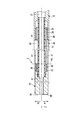
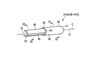
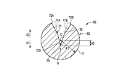
- FIG. 7 is a diagram showing the configuration of the probe main body 27.
- the probe main body 27 includes one or more (four in this embodiment) transmission units 61A to 61D.
- the ultrasonic vibration has three antinode positions A2 to A4 between the connection antinode position A1 where the proximal end of the probe main body 27 is located and the connection antinode position A5 where the tip of the probe main body 27 is located.
- the antinode position A3 is located on the distal direction side of the antinode position A2, and the antinode position A4 is located on the distal direction side of the antinode position A3.
- the transmission unit 61A extends along the longitudinal axis C from the connection antinode position A1 to the antinode position A2, and the transmission unit 61B extends along the longitudinal axis C from the antinode position A2 to the antinode position A3.
- the transmission unit 61C extends along the longitudinal axis C from the antinode position A3 to the antinode position A4, and the transmission unit 61D extends along the longitudinal axis C from the antinode position A4 to the connection antinode position A5.
- the front end of the transmission unit 61A and the base end of the transmission unit 61B are continuous at the antinode position A2, and the front end of the transmission unit 61B and the base end of the transmission unit 61C are continuous at the antinode position A3.
- antinode position A4 between the front-end
- the node position N1 is positioned between the connection antinode position A1 and the antinode position A2, and the node position N2 is positioned between the antinode position A2 and the antinode position A3.
- the node position N3 is located between the antinode position A3 and the antinode position A4, and the node position N4 is located between the antinode position A4 and the connection antinode position A5.
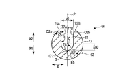
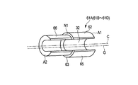
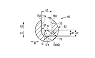
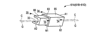
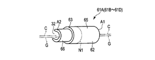
- FIG. 8 is a diagram showing a configuration of a certain transmission unit 61A.
- 9 is a cross-sectional view taken along line IX-IX in FIG. 8
- FIG. 10 is a cross-sectional view taken along line XX in FIG.
- the transmission unit 61A will be described, but the other transmission units 61B to 61D are the same as the transmission unit 61A.
- the transmission unit 61 ⁇ / b> A includes a unit outer surface 62 that is a part of the outer peripheral portion (outer surface) of the probe main body 27.
- the unit outer surface 62 is extended along the longitudinal axis C in a state exposed to the outside.
- the groove-shaped portion 32 is formed over the entire length in the axis parallel direction. Therefore, also in the transmission unit 61 ⁇ / b> A, the groove-shaped portion 32 is defined by the groove defining portion 31 over the entire length in the axis parallel direction. As described above, the groove portion 32 is recessed in the first vertical direction (the direction of the arrow X1 in FIGS.
- the transmission unit 61A includes a cross-sectional area changing unit 63 in which the cross-sectional area of the ultrasonic probe 3 perpendicular to the longitudinal axis C changes.
- the cross-sectional area changing portion 63 is formed in a step shape and is located at the node position N1 of ultrasonic vibration in the axis parallel direction. That is, the node position N1 is a cross-sectional area changing node position at which the cross-sectional area of the ultrasonic probe 3 perpendicular to the longitudinal axis C changes.
- the transmission unit 61A includes a first unit component 65 extending along the longitudinal axis C between the connection antinode position (first antinode position) A1 and the cross sectional area changing portion 63, and a cross sectional area change. And a second unit component 66 extending along the longitudinal axis C between the portion 63 and the antinode position (second antinode position) A2. That is, the first unit component 65 extends between the connection antinode position (first antinode position) A1 and the node position (cross-sectional area changing node position) N1, and the second unit component 66 is the node position.
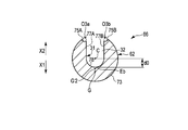
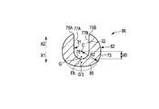
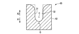
- FIG. 9 shows a cross section perpendicular to the longitudinal axis C in the first unit component 65
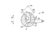
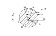
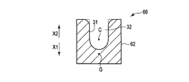
- FIG. 10 shows a cross section perpendicular to the longitudinal axis C in the second unit component 66.
- the first unit component 65 has a first cross-sectional shape having a first cross-sectional area S1 in a cross section perpendicular to the longitudinal axis C.
- the second unit component 66 has a second cross-sectional shape that has a second cross-sectional area S ⁇ b> 2 smaller than the first cross-sectional area S ⁇ b> 1 in a cross-section perpendicular to the longitudinal axis C. . Therefore, in the cross-sectional area changing portion 63, the cross-sectional area of the ultrasonic probe 3 (probe main body portion 27) perpendicular to the longitudinal axis C decreases.
- the amplitude of the ultrasonic vibration is increased in the cross-sectional area changing unit 63. Also at the node positions N2 to N4, the amplitude of the ultrasonic vibration is expanded in the same manner as the node position N1. Thereby, the ultrasonic vibration whose amplitude is enlarged is transmitted to the distal end surface 36 of the ultrasonic probe 3.
- the first unit component 65 of the transmission unit 61B is continuous with the distal direction side of the second unit component 66 of the transmission unit 61A. ing. That is, at the antinode position A2, the cross-sectional area of the ultrasonic probe 3 (probe main body 27) perpendicular to the longitudinal axis C increases from the second cross-sectional area S2 to the first cross-sectional area S1.
- the amplitude of the ultrasonic vibration does not change at the antinode position A2 between the transmission unit 61A and the transmission unit 61B.
- the amplitude of the ultrasonic vibration does not change as in the antinode position A2.
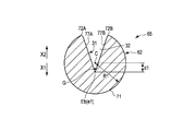
- the first unit component 65 includes a first arcuate surface 71 that is located at a distance of the first radial dimension R1 from the longitudinal axis C in the first cross-sectional shape.
- the first arcuate surface 71 is a part of the unit outer surface 62 and extends in an arcuate shape with the longitudinal axis C as the center.
- the first unit component 65 includes first chamfered portions 72A and 72B that are continuous between the first arcuate surface 71 and the groove defining portion 31 in the first cross-sectional shape.
- the first chamfered portions 72 ⁇ / b> A and 72 ⁇ / b> B are part of the unit outer surface 62.
- the first arcuate surface 71 is continuous in the direction around the longitudinal axis between the first chamfered portion 72A and the first chamfered portion 72B. Therefore, in the first cross-sectional shape, on the first vertical direction side from the longitudinal axis C, the first arcuate surface 71 is continuous as the outer surface (outer peripheral portion).
- the first chamfered portions 72A and 72B are not provided, and the first virtual shape (the shape indicated by the dotted line in FIG. 9)
- the cross-sectional area perpendicular to the longitudinal axis C is reduced by 1 reduction area S′1. That is, the first cross-sectional area S1 of the first cross-sectional shape is a cross-sectional area that is reduced by the first reduced area S′1 from the cross-sectional area of the first virtual shape.
- the first arcuate surface 71 and the groove defining portion 31 are directly continuous (without relaying the first chamfered portions 72A and 72B). .
- the second unit component 66 has a second cross-sectional shape that is located away from the longitudinal axis C by a second radial dimension R2 that is smaller than the first radial dimension R1.
- An arcuate surface 73 is provided.
- the second arcuate surface 73 is a part of the unit outer surface 62 and extends in an arcuate shape with the longitudinal axis C as the center.
- the second unit component 66 includes second chamfered portions 75A and 75B that are continuous between the second arcuate surface 73 and the groove defining portion 31 in the second cross-sectional shape.
- the second chamfered portions 75 ⁇ / b> A and 75 ⁇ / b> B are part of the unit outer surface 62.
- the second arcuate surface 73 is continuous in the direction around the longitudinal axis between the second chamfered portion 75A and the second chamfered portion 75B. Therefore, in the second cross-sectional shape, on the first vertical direction side from the longitudinal axis C, the second arcuate surface 73 is continuous as the outer surface (outer peripheral portion).
- the second chamfered portions 75A and 75B are not provided, and the second virtual shape (the shape indicated by the dotted line in FIG. 10)
- the cross-sectional area perpendicular to the longitudinal axis C is reduced by a reduced area S′2 of 2. That is, the second cross-sectional area S2 of the second cross-sectional shape is a cross-sectional area that is reduced from the cross-sectional area of the second virtual shape by the second reduced area S′2.
- the second arcuate surface 73 and the groove defining portion 31 are directly continuous (without relaying the second chamfered portions 75A and 75B). .
- the groove defining portion 31 extends in a substantially U shape in a cross section perpendicular to the longitudinal axis C. That is, the groove defining portion 31 includes groove side surfaces 77A and 77B (first groove side surface 77A and second groove surface) extending in parallel with the first vertical direction and the second vertical direction in a cross section perpendicular to the longitudinal axis C. A groove side surface 77B) and a groove bottom surface 78 continuous between the groove side surface 77A and the groove side surface 77B in a cross section perpendicular to the longitudinal axis C.
- the groove bottom surface 78 is formed in an arc shape in a cross section perpendicular to the longitudinal axis C.
- the position of the groove bottom surface 78 with the longitudinal axis C as a reference position is aligned over the entire length in the axis parallel direction. Therefore, in the transmission unit 61A (61B to 61D), the position of the groove bottom end Eb with the longitudinal axis C in the cross section perpendicular to the longitudinal axis C as the reference position in the first vertical direction and the second vertical direction is It coincides over the entire length in the axis parallel direction. That is, the position of the groove bottom end Eb with the longitudinal axis C as the reference position changes between the first cross-sectional shape of the first unit component 65 and the second cross-sectional shape of the second unit component 66. do not do.
- the groove bottom end Eb of the groove-shaped portion 32 is located on the first vertical direction side from the longitudinal axis C over the entire length of the transmission unit 61A in the axis parallel direction. Therefore, in this embodiment, the groove bottom end Eb of the groove-shaped portion 32 is separated from the longitudinal axis C by the predetermined bottom end dimension d0 in the first vertical direction over the entire length of the transmission unit 61A in the axis parallel direction. positioned.
- a reference axis P that is parallel to the first vertical direction and the second vertical direction and passes through the longitudinal axis C is defined.
- a direction perpendicular to the longitudinal axis C and perpendicular to the reference axis P (first vertical direction and second vertical direction) is defined as a groove width direction (the direction of arrow B in FIGS. 9 and 10).
- the dimension of the groove-shaped part 32 in the groove width direction is the groove width dimension.
- the first virtual shape has the same predetermined radius as the first cross-sectional shape in the first columnar shape having the same radius as the first radial dimension R1 and point-symmetric about the longitudinal axis.
- This is a shape in which a groove-like portion 32 having a bottom end dimension d0 and a predetermined groove width dimension b0 is formed.
- the first arcuate surface 71 and the groove defining portion 31 are directly continuous.
- the second virtual shape has a predetermined bottom that is the same as the second cross-sectional shape in a second columnar shape having the same radius as the second radial dimension R2 and point-symmetrical about the longitudinal axis.
- the second arcuate surface 73 and the groove defining portion 31 are directly continuous.
- the second columnar shape is a similar shape obtained by reducing the first columnar shape.
- the radial dimension between the longitudinal axis C and the outer surface is the second dimension.
- the second radial dimension R2 of the virtual shape is smaller than the first radial dimension R1 of the first virtual shape.
- the dimensions match.
- the first chamfered portions 72A and 72B are not provided in the first virtual shape, and the second chamfered portions 75A and 75B are not provided in the second virtual shape.
- the second virtual centroid position G′2 which is the centroid position of the second virtual shape, is compared to the first vertical centroid position G′1, which is the centroid position of the first virtual shape. Located on the direction side.
- the first chamfered portions 72A and 72B are provided, and the first chamfered portions 72A and 72B are relayed between the first arcuate surface 71 and the groove defining portion 31. (Indirectly) and continuous.
- the second chamfered portions 75A and 75B are provided, and the second chamfered portions 75A and 75B are relayed between the second arcuate surface 73 and the groove defining portion 31. It is continuous (indirectly).
- the shape of the second chamfered portions 75A and 75B with respect to the first chamfered portions 72A and 72B changes between the first cross-sectional shape and the second cross-sectional shape.
- the second chamfered portions 75A and 75B have the same center-of-gravity position G in the first unit component 65 and the second unit component 66 when the longitudinal axis C in the cross section perpendicular to the longitudinal axis C is the reference position.
- the shape changes to the first chamfered portions 72A and 72B.
- the first chamfered portions 72A and 72B are first curved surface portions formed in an arc shape in the first cross-sectional shape.
- the arc centers O1a, O1b of the first curved surface portions (72A, 72B) are located on the inner circumferential direction side from the unit outer surface 62 (first arc-shaped surface 71).
- the 1st curved surface part (72A, 72B) has the 1st curvature radius r1.
- the second chamfered portions 75A and 75B are second curved surface portions formed in an arc shape in the second cross-sectional shape.
- the arc centers O2a, O2b of the second curved surface portions (75A, 75B) are located on the inner circumferential direction side from the unit outer surface 62 (second arcuate surface 73).
- the 2nd curved surface part (75A, 75B) has the 2nd curvature radius r2 smaller than the 1st curvature radius r1.
- the ratio of the first reduced area S′1 to the first cross-sectional area S1 is defined as the first area ratio.
- the ratio of the second reduced area S′2 to the second cross-sectional area S2 is set as the second area ratio.
- the second curvature radius r2 of the second chamfered portions 75A and 75B is smaller than the first radius of curvature r1 of the first chamfered portions 72A and 72B.
- the second area ratio is smaller than the first area ratio. That is, in the region on the second vertical direction side from the longitudinal axis C, the second virtual area is smaller than the area ratio (first area ratio) that decreases due to the shape change from the first virtual shape to the first cross-sectional shape.
- the center-of-gravity position G when the longitudinal axis C in the section perpendicular to the longitudinal axis C is the reference position is the first unit component between the first sectional shape and the second sectional shape.
- the shape of the second chamfered portions 75A and 75B with respect to the first chamfered portions 72A and 72B is changed to a state in which the second chamfered portion 65A and the second unit constituting portion 66 coincide. That is, between the first cross-sectional shape and the second cross-sectional shape, the center-of-gravity position G when the longitudinal axis C in the cross-section perpendicular to the longitudinal axis C is the reference position is the first unit component 65 and the second cross-sectional shape.
- the shape of the unit outer surface 62 in the cross section perpendicular to the longitudinal axis C changes to a state in which the two unit constituent parts 66 coincide with each other. Since the center of gravity G when the longitudinal axis C in the cross section perpendicular to the longitudinal axis C is the reference position is the same in the first unit component 65 and the second unit component 66, the transmission unit 61A has the longitudinal axis The center-of-gravity position G when the longitudinal axis C in the cross section perpendicular to C is taken as the reference position coincides over the entire length in the axis parallel direction.
- the center-of-gravity position G with the longitudinal axis C in the cross section perpendicular to the longitudinal axis C as the reference position extends over the entire length in the axis parallel direction.
- the center-of-gravity position G when the longitudinal axis C in the cross section perpendicular to the longitudinal axis C is the reference position does not change between the transmission unit 61A and the transmission unit 61B.
- the longitudinal length in the cross section perpendicular to the longitudinal axis C The center-of-gravity position G with the axis C as the reference position does not change. Therefore, the gravity center position G when the longitudinal axis C in the cross section perpendicular to the longitudinal axis C is set as the reference position coincides with the entire length of the probe main body 27 in the axis parallel direction.
- the gravity center position G is located on the reference axis P in the cross section perpendicular to the longitudinal axis C. That is, in the probe main body 27, the gravity center position G is not shifted in the groove width direction with respect to the longitudinal axis C. Further, in the probe main body 27, the gravity center position G is shifted from the longitudinal axis C to the first vertical direction side.
- FIG. 11 is a cross-sectional view taken along line 11-11 in FIG.
- a cylindrical seal member 81 is provided in the cavity 42 between the probe main body 27 and the sheath 4 of the ultrasonic probe 3.
- the seal member 81 is located at any one of the ultrasonic vibration node positions N1 to N4, and in this embodiment, is located at the node position N2.
- an elastic member 82 such as rubber is provided at the node position N2. The elastic member 82 can be engaged with the groove-shaped portion 32 of the probe main body portion 27.
- a cylindrical shape is formed by the probe main body 27 and the elastic member 82 in a cross section perpendicular to the longitudinal axis C.
- the inner peripheral part of the cylindrical seal member 81 is in close contact with the outer peripheral part (outer surface) of the probe main body part 27 and the outer peripheral part of the elastic member 82.
- the outer peripheral portion of the seal member 81 is in close contact with the inner peripheral portion of the sheath 4. Therefore, at the node position N2, the space between the probe main body 27 and the sheath 4 is kept airtight and liquid tight.
- the probe can be obtained even at the node positions (N 1 to N 4) where the cross-sectional shape perpendicular to the longitudinal axis C is located on the probe main body 27 that is asymmetric with respect to the longitudinal axis C.
- the space between the main body 27 and the sheath 4 is kept airtight and liquid tight.
- ultrasonic suction of a living tissue is performed using the ultrasonic treatment apparatus 1
- an ultrasonic current is supplied from the ultrasonic control unit 8 to the ultrasonic transducer 13 via the electric signal lines 16 ⁇ / b> A and 16 ⁇ / b> B.
- Ultrasonic vibration is generated in the vibrator 13.
- the generated ultrasonic vibration is transmitted to the ultrasonic probe 3 through the horn member 12.
- ultrasonic vibration is transmitted from the proximal direction to the distal direction.
- the cross-sectional shape perpendicular to the longitudinal axis C changes from a point-symmetrical shape about the longitudinal axis C to the longitudinal axis C.
- the shape changes to an asymmetrical shape around the center.
- the ultrasonic vibration transmission direction and the cross-sectional shape perpendicular to the vibration direction greatly change at the connection antinode position A1.
- the ultrasonic vibration stress is zero at the ultrasonic vibration antinode position including the connection antinode position A1. Therefore, no stress acts on the ultrasonic vibration at the connection antinode position A1 where the ultrasonic vibration transmission direction and the cross-sectional shape perpendicular to the vibration direction change greatly. Therefore, the vibration mode does not change.
- the ultrasonic vibration transmission direction and the cross-sectional shape perpendicular to the vibration direction are large at the connection antinode position A5 located at the distal end of the probe main body 27 (the proximal end of the distal probe member 25). Change. As described above, the stress due to the ultrasonic vibration is zero at the connection antinode position A5. Accordingly, no stress acts on the ultrasonic vibration at the connection antinode position A5 where the ultrasonic vibration transmission direction and the cross-sectional shape perpendicular to the vibration direction change greatly. Therefore, the vibration mode does not change.
- the position at which the cross-sectional shape perpendicular to the longitudinal axis C changes from a point-symmetrical shape about the longitudinal axis C to an asymmetrical shape about the longitudinal axis C is the ultrasonic probe 3 and the horn member 12. Even when provided, the ultrasonic vibration is not affected by the stress.
- each of the transmission units 61A to 61D of the probe main body 27 is provided with a cross-sectional area changing portion 63.
- the cross-sectional area changing portion 63 is provided at the node positions (N1 to N4) located at the antinode positions of the ultrasonic vibration.
- the cross-sectional area perpendicular to the longitudinal axis C decreases. For this reason, in the cross-sectional area change part 63, the amplitude of ultrasonic vibration is expanded.
- the amplitude of the ultrasonic vibration is increased, whereby the amplitude is increased on the distal end surface 36 of the ultrasonic probe 3. Treatment is performed using ultrasonic vibration.
- each of the transmission units 61A to 61D there is a longitudinal difference between the first cross-sectional shape of the first unit component 65 and the second cross-sectional shape of the second unit component 66.
- the gravity center position G with the axis C as the reference position does not change. That is, in each of the transmission units 61A to 61D, the center-of-gravity position G when the longitudinal axis C in the cross section perpendicular to the longitudinal axis C is used as the reference position is the same over the entire length in the axis parallel direction.
- the longitudinal axis The center-of-gravity position G when the longitudinal axis C in the cross section perpendicular to C is taken as the reference position does not change at the cross-sectional area changing portion 63. That is, in the probe main body 27, the center-of-gravity position G when the longitudinal axis C in the cross section perpendicular to the longitudinal axis C is set as the reference position at positions other than the antinode position of the ultrasonic vibration does not change.
- the cross-sectional area changing portion 63 is provided in each of the transmission units 61A to 61D whose cross-sectional shape perpendicular to the longitudinal axis C is asymmetric with respect to the longitudinal axis C, the ultrasonic vibration is affected by the stress. Not receive.
- the ultrasonic vibration is not affected by the stress. Therefore, the transmission property of the ultrasonic vibration is ensured, and the ultrasonic vibration is appropriately transmitted to the distal end surface 36 of the ultrasonic probe 3 (front end side probe member 25). Further, since the ultrasonic vibration is hardly affected by the stress, the strength of the ultrasonic probe 3 is ensured.
- Cavitation is generated by transmitting ultrasonic vibration to the distal end surface 36 of the distal end side probe member 25 (ultrasonic probe 3).
- ultrasonic vibration By cavitation, biological tissue with low elasticity such as hepatocytes is selectively crushed and excised.
- ultrasonic vibration By appropriately transmitting ultrasonic vibration to the distal end surface 36 of the ultrasonic probe 3, cavitation is more efficiently generated, and treatment such as ultrasonic suction is appropriately performed using the cavitation.
- each of the transmission units 61A to 61D the position of the groove bottom end Eb with the longitudinal axis C in the cross section perpendicular to the longitudinal axis C as the reference position in the first vertical direction and the second vertical direction is axially parallel. Match over the entire length in the direction. For this reason, in each of the transmission units 61A to 61D, the groove portion 32 is easily formed by milling. In addition, the first chamfered portions 72A and 72B and the second chamfered portions 75A and 75B are formed in a short time and at a low cost. Therefore, the transmission units 61A to 61D are formed efficiently and at low cost. Therefore, the probe main body 27 and the ultrasonic probe 3 can be manufactured efficiently and at low cost.
- proximal end side connecting portion 28 for connecting the probe main body portion 27 to the horn member 12 and the distal end side connecting portion 33 for connecting the probe main body portion 27 to the distal end side probe member 25 are formed in a cylindrical shape. That is, in the proximal end side connection portion 28 and the distal end side connection portion 33, the cross-sectional shape perpendicular to the longitudinal axis C is point symmetric about the longitudinal axis C. For this reason, even when the probe main body portion 27 whose cross-sectional shape perpendicular to the longitudinal axis C is asymmetric with respect to the longitudinal axis C is provided, the strength of the proximal end side connection portion and the distal end side connection portion 33 is ensured.
- the elastic member 82 causes the probe main body portion 27 to cross the probe main body portion 27 at the node position (N2) where the cross-sectional shape perpendicular to the longitudinal axis C is located on the probe main body portion 27 that is asymmetric about the longitudinal axis C Airtightness and liquid tightness are maintained between the sheath 4. For this reason, the pressure in the abdominal cavity is maintained in the treatment with the abdominal cavity. Moreover, in the treatment in the abdominal cavity, the outflow of fluid such as body fluid from the abdominal cavity toward the proximal end is effectively prevented.
- the shapes of the first chamfered portions 72A and 72B and the second chamfered portions 75A and 75B are not limited to the shapes of the first embodiment.
- the second chamfered portions 75A and 75B may be formed in an inclined plane shape.
- the second chamfered portions 75A and 75B are inclined with respect to the first vertical direction (the direction of the arrow X1 in FIG. 12) and the second vertical direction (the direction of the arrow X2 in FIG. 12). It is extended by.
- the second chamfered portions 75A and 75B may be formed in a concave curved surface in the second cross-sectional shape of the second unit component 66.
- the second chamfered portions 75A and 75B are formed in an arc shape in which arc centers O3a and O3b are located on the outer peripheral direction side from the unit outer surface 62 (second arcuate surface 73).
- the arc center O3a of the second chamfered portion 75A and the arc center O3b of the second chamfered portion 75B have different positions.
- the second chamfered portions 75A and 75B have the same arc center O4. May be. Also in this modified example, the arc center O4 is located on the outer circumferential direction side from the unit outer surface 62 (second arcuate surface 73), as in the second modified example.
- the second chamfered portions 75A and 75B are provided in the first vertical direction and the second It may be formed in a planar shape perpendicular to the vertical direction.
- the second chamfered portions 75A and 75B are extended in parallel to the groove width direction.
- the first chamfered portions 72A and 72B also have a shape such as an inclined flat surface and a concave curved surface in the first cross-sectional shape of the first unit component 65, similarly to the second chamfered portions 75A and 75B. May be formed.
- the first cross-sectional area S1 of the first cross-sectional shape of the first unit component 65 is provided. Accordingly, the second cross-sectional area S2 of the second cross-sectional shape of the second unit component 66 is small.
- the longitudinal axis C in the second sectional shape is determined from the first radial dimension R1 from the longitudinal axis C in the first sectional shape to the first arcuate surface 71. To the second arcuate surface 73 is small in the second radial dimension R2.
- each of the transmission units 61A to 61D in the cross section perpendicular to the longitudinal axis C, the groove having the longitudinal axis C in the first vertical direction and the second vertical direction as a reference position.
- the position of the bottom end Eb coincides over the entire length in the axis parallel direction.
- the groove width dimension between the groove side surface 77A and the groove side surface 77B is the same over the entire length in the axis parallel direction.
- the second virtual shape (see FIG. 9) is compared to the first virtual center-of-gravity position G′1 of the first virtual shape (the shape indicated by the dotted line in FIG. 9).
- the second virtual center-of-gravity position G′2 of the shape shown by the dotted line in FIG. 12 to FIG. 15 is located on the first vertical direction side. Therefore, in the first to fourth modified examples, as in the first embodiment, the first area ratio of the first reduced area S′1 to the first sectional area S1 is The second area ratio of the second reduced area S′2 to the sectional area S2 of 2 is reduced.
- the second virtual center of gravity position G′2 of the second virtual shape is located on the first vertical direction side from the first virtual center of gravity position G′1 of the first virtual shape, but the first cross section Between the shape and the second cross-sectional shape, the center-of-gravity position G when the longitudinal axis C is taken as the reference position coincides.
- the center-of-gravity position G when the longitudinal axis C in the cross section perpendicular to the longitudinal axis C is the reference position is The shape of the second chamfered portions 75A and 75B with respect to the first chamfered portions 72A and 72B is changed to a state in which the first unit constituting portion 65 and the second unit constituting portion 66 coincide with each other.
- the groove defining portion 31 extends in a substantially U shape in a cross section perpendicular to the longitudinal axis C, but the present invention is not limited to this.
- the groove defining portion 31 may be extended in a substantially V shape in a cross section perpendicular to the longitudinal axis C.
- the groove bottom surface 78 is not provided, and groove side surfaces 77A and 77B are provided.
- the groove side surfaces 77A and 77B are inclined with respect to the first vertical direction (the direction of the arrow X1 in FIGS. 16 and 17) and the second vertical direction (the direction of the arrow X2 in FIGS. 16 and 17). It is extended.
- the second unit component is obtained from the first cross-sectional area S1 of the first cross-sectional shape of the first unit component 65, as in the first embodiment.
- the second sectional area S2 of the second sectional shape 66 is small.
- the longitudinal axis C in the second sectional shape is determined from the first radial dimension R1 from the longitudinal axis C in the first sectional shape to the first arcuate surface 71.
- To the second arcuate surface 73 is small in the second radial dimension R2.
- each of the transmission units 61A to 61D in the cross section perpendicular to the longitudinal axis C, the groove having the longitudinal axis C in the first vertical direction and the second vertical direction as a reference position.
- the position of the bottom end Eb coincides over the entire length in the axis parallel direction.
- the second virtual shape (the shape indicated by the dotted line in FIG. 17) is compared with the first virtual center of gravity position G′1 of the first virtual shape (the shape indicated by the dotted line in FIG. 16).
- the second virtual center-of-gravity position G′2 is located on the first vertical direction side. Therefore, in the present modification, as in the first embodiment, the second area with respect to the second cross-sectional area S2 is compared with the first area ratio of the first reduced area S′1 with respect to the first cross-sectional area S1. The second area ratio of the decrease area S′2 is reduced.
- the second virtual center of gravity position G′2 of the second virtual shape is located on the first vertical direction side from the first virtual center of gravity position G′1 of the first virtual shape, but the first cross section Between the shape and the second cross-sectional shape, the center-of-gravity position G when the longitudinal axis C is taken as the reference position coincides.
- the center-of-gravity position G when the longitudinal axis C in the cross section perpendicular to the longitudinal axis C is the reference position is The shape of the second chamfered portions 75A and 75B with respect to the first chamfered portions 72A and 72B is changed to a state in which the first unit constituting portion 65 and the second unit constituting portion 66 coincide with each other.
- the unit outer surface 62 of each of the transmission units 61A to 61D has the first cross-sectional shape from the longitudinal axis C to the first A first arcuate surface 71 that is spaced apart by a radial dimension R1 and a second cross-sectional shape that is spaced apart from the longitudinal axis C by a second radial dimension R2 that is smaller than the first radial dimension R1. 2 arcuate surfaces 73 may be provided.
- the position of the groove bottom end Eb with the longitudinal axis C as the reference position in the first vertical direction and the second vertical direction is axially parallel.
- the groove-shaped part 32 should just be prescribed
- the position of the center of gravity when the longitudinal axis C in the cross section perpendicular to the longitudinal axis C is the reference position is the first unit component 65 and the second sectional shape.
- the shape of the second chamfered portions 75A and 75B with respect to the first chamfered portions 72A and 72B may be changed to a state in which the unit constituent portions 66 coincide with each other.
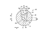
- FIG. 18 is a diagram showing a configuration of a certain transmission unit 61A.
- 19 is a cross-sectional view taken along line 19-19 in FIG. 18, and
- FIG. 20 is a cross-sectional view taken along line 20-20 in FIG.
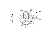
- 19 shows a cross section perpendicular to the longitudinal axis C in the first unit component 65
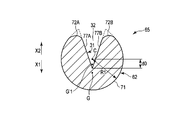
- FIG. 20 shows a cross section perpendicular to the longitudinal axis C in the second unit component 66.
- the second cross-sectional shape of the second unit component 66 is also larger than the first cross-sectional area S1 of the first cross-sectional shape of the first unit component 65.
- the second cross-sectional area S2 becomes small. Therefore, in the cross-sectional area changing portion 63, the cross-sectional area of the ultrasonic probe 3 (probe main body portion 27) perpendicular to the longitudinal axis C decreases. Since the cross-sectional area of the ultrasonic probe 3 perpendicular to the longitudinal axis C decreases at the node position N1 other than the antinode position of the ultrasonic vibration, the amplitude of the ultrasonic vibration is increased in the cross-sectional area changing unit 63. Thereby, also in this embodiment, the ultrasonic vibration whose amplitude is expanded is transmitted to the distal end surface 36 of the ultrasonic probe 3.
- the first unit component 65 includes a first arcuate surface 71 positioned away from the longitudinal axis C by a first radial dimension R1 in the first cross-sectional shape.
- the first unit component 65 includes first chamfered portions 72A and 72B that are continuous between the first arcuate surface 71 and the groove defining portion 31 in the first cross-sectional shape.
- the first arcuate surface 71 is continuous in the direction around the longitudinal axis between the first chamfered portion 72A and the first chamfered portion 72B. Therefore, in the first cross-sectional shape, on the first vertical direction side from the longitudinal axis C, the first arcuate surface 71 is continuous as the outer surface (outer peripheral portion).
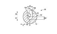
- the second unit component 66 has a second cross-sectional shape that is located away from the longitudinal axis C by a second radial dimension R2 that is smaller than the first radial dimension R1.
- An arcuate surface 73 is provided.
- the second unit component 66 includes second chamfered portions 75A and 75B that are continuous between the second arcuate surface 73 and the groove defining portion 31 in the second cross-sectional shape.
- the second unit component 66 includes a dimension reduction surface 85 whose radial dimension from the longitudinal axis C is smaller than the second radial dimension R2.
- the dimension reduction surface 85 is a part of the unit outer surface 62 and is provided on the first vertical direction side from the gravity center position G in the second cross-sectional shape.
- the dimension reduction surface 85 is formed in a planar shape in the second cross-sectional shape.
- the second arcuate surface 73 is not continuous in the direction around the longitudinal axis between the second chamfered portion 75A and the second chamfered portion 75B. That is, in the second cross-sectional shape, the second arcuate surface 73 is not continuous as the outer surface (outer peripheral portion) on the first vertical direction side from the longitudinal axis C.
- the virtual area (the shape indicated by the dotted line in FIG. 20) in which the dimension reducing surface 85 is not provided is perpendicular to the longitudinal axis C by the reduced area S′3.
- the cross-sectional area is decreasing. That is, the second cross-sectional area S2 of the second cross-sectional shape is a cross-sectional area that is reduced from the virtual cross-sectional area by the reduced area S′3.
- the second arcuate surface 73 is continuous in the direction around the longitudinal axis between the second chamfered portion 75A and the second chamfered portion 75B.
- the groove defining portion 31 extends in a substantially U shape in a cross section perpendicular to the longitudinal axis C.
- the position of the groove bottom surface 78 with the longitudinal axis C as the reference position in the cross section perpendicular to the longitudinal axis C is the entire length in the axis parallel direction. Match across. Therefore, in the transmission unit 61A (61B to 61D), the position of the groove bottom end Eb with the longitudinal axis C in the cross section perpendicular to the longitudinal axis C as the reference position in the first vertical direction and the second vertical direction is It coincides over the entire length in the axis parallel direction. That is, the position of the groove bottom end Eb with the longitudinal axis C as the reference position changes between the first cross-sectional shape of the first unit component 65 and the second cross-sectional shape of the second unit component 66. do not do.
- the width dimension is consistent over the entire length in the axial parallel direction. That is, in the transmission unit 61A (61B to 61D), a predetermined groove width dimension b0 is provided between the groove side surface 77A and the groove side surface 77B in the groove width direction over the entire length in the axis parallel direction. Therefore, the groove width dimension between the groove side surface 77A and the groove side surface 77B changes between the first cross-sectional shape of the first unit component 65 and the second cross-sectional shape of the second unit component 66. do not do.
- first chamfered portions 72A and 72B of the present embodiment are first curved surface portions formed in an arc shape in the first sectional shape, and in the first sectional shape, the first curved surface portion (72A , 72B) are located closer to the inner circumferential direction than the unit outer surface 62 (first arcuate surface 71).
- the second chamfered portions 75A and 75B are second curved surface portions formed in an arc shape in the second cross-sectional shape, and in the second cross-sectional shape, the second curved surface portions (75A and 75B).
- the arc centers O2a and O2b are located on the inner circumferential direction side of the unit outer surface 62 (second arcuate surface 73).
- the first curved surface portion (72A, 72B) and the second curved surface portion (75A, 75B) have the same radius of curvature r0. Accordingly, in the present embodiment, unlike the first embodiment, the second chamfered portions 75A and 75B with respect to the first chamfered portions 72A and 72B between the first cross-sectional shape and the second cross-sectional shape. The shape does not change.
- the first cross-sectional shape is a first columnar shape having the same radius as the first radial dimension R1 and point-symmetric about the longitudinal axis, and has a predetermined bottom end dimension d0 and a predetermined groove.
- This is a shape in which a groove-like portion 32 having a width dimension b0 is formed.
- first chamfered portions 72A and 72B are formed.
- the virtual shape and the second cross-sectional shape have a predetermined bottom end dimension d0 and a predetermined shape in a second columnar shape having the same radius as the second radial dimension R2 and point-symmetric about the longitudinal axis.
- the groove-shaped portion 32 having the groove width dimension b0 is formed.
- second chamfered portions 75A and 75B having the same radius of curvature r0 as the first chamfered portions 72A and 72B are formed.
- the second columnar shape is a similar shape obtained by reducing the first columnar shape.
- the virtual shape second Is smaller than the first radial dimension R1 of the first cross-sectional shape.
- the position of the groove bottom end Eb of the groove-shaped portion 32 with the longitudinal axis C as the reference position and the groove width dimension between the groove side surface 77A and the groove side surface 77B are equal. I'm doing it.
- the first chamfered portions 72A and 72B having the first cross-sectional shape and the second chamfered portions 75A and 75B having the virtual shape substantially coincide with each other in a cross section perpendicular to the longitudinal axis.
- the first arcuate surface 71 is continuous between the first chamfered portion 72A and the first chamfered portion 72B in the first cross-sectional shape, and the second chamfered portion 75A and the second chamfered in the virtual shape.
- the second arcuate surface 73 is continuous with the portion 75B.
- a dimension reducing surface 85 is provided on the first vertical direction side from the gravity center position G.
- the second arcuate surface 73 is not continuous between the second chamfered portion 75A and the second chamfered portion 75B in the second cross-sectional shape. Then, between the first cross-sectional shape and the second cross-sectional shape, the shape of the dimension reducing surface 85 with respect to the first arcuate surface 71 changes on the first vertical direction side from the gravity center position G.
- the dimension reduction surface 85 is in a state where the center of gravity G when the longitudinal axis C in the cross section perpendicular to the longitudinal axis C is the reference position is the same in the first unit component 65 and the second unit component 66.
- the shape changes with respect to the first arcuate surface 71.
- the second cross-sectional area S2 is reduced from the virtual cross-sectional area by the reduced area S′3. That is, in the region on the first vertical direction side from the gravity center position G, the cross-sectional area decreases due to the shape change from the virtual shape to the second cross-sectional shape. For this reason, the virtual center of gravity G′3 of the virtual shape is located on the first vertical direction side from the center of gravity G of the first cross-sectional shape, but between the first cross-sectional shape and the second cross-sectional shape, The center of gravity position G when the longitudinal axis C is set as the reference position coincides.
- the center-of-gravity position G when the longitudinal axis C in the section perpendicular to the longitudinal axis C is the reference position is the first unit component between the first sectional shape and the second sectional shape.
- the shape of the dimension reducing surface 85 with respect to the first arcuate surface 71 is changed to a state in which the first unit arcuate surface 71 and the second unit constituent portion 66 coincide. That is, between the first cross-sectional shape and the second cross-sectional shape, the center-of-gravity position G when the longitudinal axis C in the cross-section perpendicular to the longitudinal axis C is the reference position is the first unit component 65 and the second cross-sectional shape.
- the shape of the unit outer surface 62 in the cross section perpendicular to the longitudinal axis C changes to a state in which the two unit constituent parts 66 coincide with each other. Since the center of gravity G when the longitudinal axis C in the cross section perpendicular to the longitudinal axis C is the reference position is the same in the first unit component 65 and the second unit component 66, the transmission unit 61A has the longitudinal axis The center-of-gravity position G when the longitudinal axis C in the cross section perpendicular to C is taken as the reference position coincides over the entire length in the axis parallel direction.
- the center-of-gravity position G with the longitudinal axis C in the cross section perpendicular to the longitudinal axis C as the reference position extends over the entire length in the axis parallel direction.
- the center-of-gravity position G when the longitudinal axis C in the cross section perpendicular to the longitudinal axis C is the reference position does not change between the transmission unit 61A and the transmission unit 61B.
- the longitudinal length in the cross section perpendicular to the longitudinal axis C The center-of-gravity position G with the axis C as the reference position does not change. Therefore, the gravity center position G when the longitudinal axis C in the cross section perpendicular to the longitudinal axis C is set as the reference position coincides with the entire length of the probe main body 27 in the axis parallel direction.
- the first cross-sectional shape and the second cross-section of the first unit component 65 are the same as in the first embodiment.
- the center-of-gravity position G with the longitudinal axis C as the reference position does not change between the second cross-sectional shape of the unit component 66. That is, in each of the transmission units 61A to 61D, the center-of-gravity position G when the longitudinal axis C in the cross section perpendicular to the longitudinal axis C is used as the reference position is the same over the entire length in the axis parallel direction.
- the center-of-gravity position G when the longitudinal axis C in the cross section is the reference position does not change at the cross-sectional area changing portion 63. That is, in the probe main body 27, the center-of-gravity position G when the longitudinal axis C in the cross section perpendicular to the longitudinal axis C is set as the reference position at positions other than the antinode position of the ultrasonic vibration does not change.
- the cross-sectional area changing portion 63 is provided in each of the transmission units 61A to 61D whose cross-sectional shape perpendicular to the longitudinal axis C is asymmetric with respect to the longitudinal axis C, the ultrasonic vibration is affected by the stress. Not receive.
- the ultrasonic probe 3 of the present embodiment since the ultrasonic vibration is not affected by the stress as in the first embodiment, the transmission property of the ultrasonic vibration is ensured, and the ultrasonic probe 3 (tip-side probe member) The ultrasonic vibration is appropriately transmitted to the tip surface 36 of 25). Further, similarly to the first embodiment, since the ultrasonic vibration is hardly affected by the stress, the strength of the ultrasonic probe 3 is ensured.
- each of the transmission units 61A to 61D the position of the groove bottom end Eb with the longitudinal axis C in the cross section perpendicular to the longitudinal axis C as the reference position in the first vertical direction and the second vertical direction is axially parallel. Match over the entire length in the direction. For this reason, in each of the transmission units 61A to 61D, the groove portion 32 is easily formed by milling. Further, the formation of the dimension reduction surface 85 is performed in a short time and at a low cost. Therefore, the transmission units 61A to 61D are formed efficiently and at low cost. Therefore, as in the first embodiment, the probe main body 27 and the ultrasonic probe 3 can be manufactured efficiently and at low cost.
- the dimension reducing surface 85 is formed in a planar shape in the second cross-sectional shape, but the present invention is not limited to this.
- the dimension reduction surface 85 may be formed in a curved surface shape in the second cross-sectional shape.
- the dimension reduction surface 85 of the second unit component 66 is provided on the first vertical direction side from the gravity center position G in the second cross-sectional shape.
- the radial dimension from the longitudinal axis C is smaller than the second radial dimension R2.
- the second unit component is obtained from the first cross-sectional area S1 of the first cross-sectional shape of the first unit component 65, as in the second embodiment.
- the second sectional area S2 of the second sectional shape 66 is small.
- the longitudinal axis C in the second sectional shape is determined from the first radial dimension R1 from the longitudinal axis C in the first sectional shape to the first arcuate surface 71.
- To the second arcuate surface 73 is small in the second radial dimension R2.
- each of the transmission units 61A to 61D in the cross section perpendicular to the longitudinal axis C, a groove having the longitudinal axis C in the first vertical direction and the second vertical direction as a reference position.
- the position of the bottom end Eb coincides over the entire length in the axis parallel direction.
- the groove width dimension between the groove side surface 77A and the groove side surface 77B is the same over the entire length in the axis parallel direction.
- the shape of 2nd chamfer part 75A, 75B does not change with respect to 1st chamfer part 72A, 72B between 1st cross-sectional shape and 2nd cross-sectional shape.
- the virtual center of gravity position G′3 of the virtual shape (the shape indicated by the dotted line in FIG. 21) is located on the first vertical direction side as compared to the center of gravity position G of the first cross-sectional shape. Yes. Therefore, in the second cross-sectional shape of this modification example, as in the second embodiment, by providing the dimension reducing surface 85, a cross-sectional area perpendicular to the longitudinal axis C is reduced from the virtual shape by the reduced area S′3. is decreasing.
- the virtual center of gravity position G′3 of the virtual shape is located on the first vertical direction side from the center of gravity position G of the first cross-sectional shape, but between the first cross-sectional shape and the second cross-sectional shape,
- the center of gravity position G when the longitudinal axis C is set as the reference position coincides. That is, as in the second embodiment, between the first cross-sectional shape and the second cross-sectional shape, the center-of-gravity position G when the longitudinal axis C in the cross section perpendicular to the longitudinal axis C is the reference position is the same.
- the shape of the dimension reducing surface 85 with respect to the first arcuate surface 71 changes to a state in which the first unit component 65 and the second unit component 66 match.
- the groove defining portion 31 extends in a substantially U shape in a cross section perpendicular to the longitudinal axis C, but the present invention is not limited to this.
- the groove defining portion 31 may be extended in a substantially V shape in a cross section perpendicular to the longitudinal axis C.
- the groove bottom surface 78 is not provided, and groove side surfaces 77A and 77B are provided.
- the groove side surfaces 77A and 77B are inclined with respect to the first vertical direction (the direction of the arrow X1 in FIGS. 22 and 23) and the second vertical direction (the direction of the arrow X2 in FIGS. 22 and 23). It is extended.
- the second unit constituent part is obtained from the first cross-sectional area S1 of the first cross-sectional shape of the first unit constituent part 65, as in the second embodiment.
- the second sectional area S2 of the second sectional shape 66 is small.
- the longitudinal axis C in the second sectional shape is determined from the first radial dimension R1 from the longitudinal axis C in the first sectional shape to the first arcuate surface 71.
- To the second arcuate surface 73 is small in the second radial dimension R2.
- each of the transmission units 61A to 61D in the cross section perpendicular to the longitudinal axis C, a groove having the longitudinal axis C in the first vertical direction and the second vertical direction as a reference position.
- the position of the bottom end Eb coincides over the entire length in the axis parallel direction.
- the virtual center of gravity position G′3 of the virtual shape (the shape indicated by the dotted line in FIG. 23) is located on the first vertical direction side as compared to the center of gravity position G of the first cross-sectional shape. Yes. Therefore, in the second cross-sectional shape of this modification example, as in the second embodiment, by providing the dimension reducing surface 85, a cross-sectional area perpendicular to the longitudinal axis C is reduced from the virtual shape by the reduced area S′3. is decreasing.
- the virtual center of gravity position G′3 of the virtual shape is located on the first vertical direction side from the center of gravity position G of the first cross-sectional shape, but between the first cross-sectional shape and the second cross-sectional shape,
- the center of gravity position G when the longitudinal axis C is set as the reference position coincides. That is, as in the second embodiment, between the first cross-sectional shape and the second cross-sectional shape, the center-of-gravity position G when the longitudinal axis C in the cross section perpendicular to the longitudinal axis C is the reference position is the same.
- the shape of the dimension reducing surface 85 with respect to the first arcuate surface 71 changes to a state in which the first unit component 65 and the second unit component 66 match.
- the unit outer surfaces 62 of the respective transmission units 61A to 61D are separated from the longitudinal axis C in the first cross-sectional shape.
- a first arcuate surface 71 that is spaced apart by a radial dimension R1 and a second cross-sectional shape that is spaced apart from the longitudinal axis C by a second radial dimension R2 that is smaller than the first radial dimension R1. 2 arcuate surfaces 73 may be provided.
- each of the transmission units 61A to 61D in the cross section perpendicular to the longitudinal axis C, the position of the groove bottom end Eb with the longitudinal axis C as the reference position in the first vertical direction and the second vertical direction is axially parallel.
- the groove-shaped part 32 should just be prescribed
- the position of the center of gravity when the longitudinal axis C in the cross section perpendicular to the longitudinal axis C is the reference position is the first unit component 65 and the second sectional shape.
- the shape of the dimension reducing surface 85 with respect to the first arcuate surface 71 may be changed to a state in which the unit constituent portions 66 coincide with each other.
- the shape of the second chamfered portions 75A and 75B with respect to the first chamfered portions 72A and 72B changes between the first cross-sectional shape and the second cross-sectional shape.
- the shape of the dimension reduction surface 85 with respect to the 1st circular arc-shaped surface 71 changes between 1st cross-sectional shape and 2nd cross-sectional shape.
- the first chamfered portions 72 ⁇ / b> A and 72 ⁇ / b> B and the second chamfered portions 75 ⁇ / b> A and 75 ⁇ / b> B are part of the unit outer surface 62.
- the first arcuate surface 71 and the dimension reducing surface 85 are a part of the unit outer surface 62.
- the outer surface 62 includes a first arcuate surface 71 positioned away from the longitudinal axis C by a first radial dimension R1 in the first cross-sectional shape, and a first diameter from the longitudinal axis C in the second cross-sectional shape.
- a second arcuate surface 73 that is spaced apart by a second radial dimension R2 that is smaller than the directional dimension R1.
- each of the transmission units 61A to 61D in the cross section perpendicular to the longitudinal axis C, the position of the groove bottom end Eb with the longitudinal axis C as the reference position in the first vertical direction and the second vertical direction is axially parallel.
- the groove-like portion 32 is defined so as to coincide with the entire length in the direction.
- the center-of-gravity position G when the longitudinal axis C in the cross-section perpendicular to the longitudinal axis C is the reference position is the first unit component 65 and the second cross-sectional shape.
- the shape of the unit outer surface 62 in the cross section perpendicular to the longitudinal axis C changes to a state in which the two unit constituent parts 66 coincide with each other.
- FIG. 24 is a diagram showing a configuration of a certain transmission unit 61A.
- FIG. 25 is a cross-sectional view perpendicular to the longitudinal axis C in the first unit component 65
- FIG. 26 is a cross-sectional view perpendicular to the longitudinal axis C in the second unit component 66.
- the transmission unit 61A will be described, but the other transmission units 61B to 61D are the same as the transmission unit 61A.
- the second cross-sectional shape of the second unit component 66 is also larger than the first cross-sectional area S1 of the first cross-sectional shape of the first unit component 65.
- the second cross-sectional area S2 becomes small. Therefore, in the cross-sectional area changing portion 63, the cross-sectional area of the ultrasonic probe 3 (probe main body portion 27) perpendicular to the longitudinal axis C decreases. Since the cross-sectional area of the ultrasonic probe 3 perpendicular to the longitudinal axis C decreases at the node position N1 other than the antinode position of the ultrasonic vibration, the amplitude of the ultrasonic vibration is increased in the cross-sectional area changing unit 63. Thereby, also in this embodiment, the ultrasonic vibration whose amplitude is expanded is transmitted to the distal end surface 36 of the ultrasonic probe 3.
- the first unit component 65 includes a first arcuate surface 71 located at a distance of the first radial dimension R1 from the longitudinal axis C in the first cross-sectional shape.
- the first unit component 65 includes first chamfered portions 72A and 72B that are continuous between the first arcuate surface 71 and the groove defining portion 31 in the first cross-sectional shape.
- the first arcuate surface 71 is continuous in the direction around the longitudinal axis between the first chamfered portion 72A and the first chamfered portion 72B. Therefore, in the first cross-sectional shape, on the first vertical direction side from the longitudinal axis C, the first arcuate surface 71 is continuous as the outer surface.
- the second unit component 66 has a second cross-sectional shape that is located away from the longitudinal axis C by a second radial dimension R2 that is smaller than the first radial dimension R1.
- An arcuate surface 73 is provided.
- the second unit component 66 includes second chamfered portions 75A and 75B that are continuous between the second arcuate surface 73 and the groove defining portion 31 in the second cross-sectional shape.
- the second arcuate surface 73 is continuous in the direction around the longitudinal axis between the second chamfered portion 75A and the second chamfered portion 75B. Therefore, in the second cross-sectional shape, on the first vertical direction side from the longitudinal axis C, the second arcuate surface 73 is continuous as the outer surface.
- the second chamfered portions 75A, 75A, 72B, 72B, and 72C are between the first cross-sectional shape and the second cross-sectional shape.
- the shape of 75B does not change.
- the groove defining portion 31 extends in a substantially U shape in a cross section perpendicular to the longitudinal axis C.
- the groove width dimension between the groove side surface (first groove side surface) 77A and the groove side surface (second groove side surface) 77B in the cross section perpendicular to the longitudinal axis C is It is consistent over the entire length in the axis parallel direction. That is, in the transmission unit 61A (61B to 61D), a predetermined groove width dimension b0 is provided between the groove side surface 77A and the groove side surface 77B in the groove width direction over the entire length in the axis parallel direction. Therefore, the groove width dimension between the groove side surface 77A and the groove side surface 77B changes between the first cross-sectional shape of the first unit component 65 and the second cross-sectional shape of the second unit component 66. do not do.
- a groove bottom surface 78 having the longitudinal axis C as a reference position in a cross section perpendicular to the longitudinal axis C. Is different between the first cross-sectional shape and the second cross-sectional shape. Therefore, in the transmission unit 61A (61B to 61D), the position of the groove bottom end Eb with the longitudinal axis C in the cross section perpendicular to the longitudinal axis C as the reference position in the first vertical direction and the second vertical direction is It changes between the first cross-sectional shape and the second cross-sectional shape.
- the groove bottom end Eb is located at the first bottom end position e1.
- the groove bottom end Eb is located at the second bottom end position e2 on the first vertical direction side from the first bottom end position e1.
- the first bottom end position e1 and the second bottom end position e2 are located on the first vertical direction side from the longitudinal axis C.
- the groove bottom end Eb is positioned at the second bottom end position e2, so that the position of the groove bottom end Eb with respect to the longitudinal axis C coincides with the first cross-sectional shape.
- the cross-sectional area perpendicular to the longitudinal axis C is reduced by the reduced area S′4. That is, the second cross-sectional area S2 of the second cross-sectional shape is a cross-sectional area that is reduced from the virtual cross-sectional area by the reduced area S′4.
- the groove bottom end Eb (first bottom end position e1) is located away from the longitudinal axis C by the first bottom end dimension d1 in the first vertical direction.
- the groove bottom end Eb (second bottom end position e2) is a first vertical direction from the longitudinal axis C by a second bottom end dimension d2 that is larger than the first bottom end dimension d1.
- the groove bottom end Eb is located away from the longitudinal axis C by the first bottom end dimension d1 in the first vertical direction.
- the first cross-sectional shape is a first columnar shape whose radius is the same as the first radial direction dimension R1 and point-symmetric about the longitudinal axis, and the first bottom end dimension d1 and a predetermined groove width dimension.
- a groove-like portion 32 having b0 is formed.
- first chamfered portions 72A and 72B are formed.
- the imaginary shape and the second cross-sectional shape are the same as the second radial dimension R2, and the groove-like portion 32 is formed in a second columnar shape that is point-symmetric about the longitudinal axis. Shape.
- the groove-shaped portion 32 has a first bottom end dimension d1 and a predetermined groove width dimension b0.
- the groove-shaped portion 32 has a second bottom end dimension d2 larger than the first bottom end dimension d1 and a predetermined groove width dimension b0.
- second chamfered portions 75A and 75B having the same shape as the first chamfered portions 72A and 72B are formed.
- the second columnar shape is a similar shape obtained by reducing the first columnar shape.
- the virtual shape second Is smaller than the first radial dimension R1 of the first cross-sectional shape.
- the position of the groove bottom end Eb of the groove-shaped portion 32 with the longitudinal axis C as the reference position and the groove width dimension between the groove side surface 77A and the groove side surface 77B are equal. I'm doing it.
- the first chamfered portions 72A and 72B having the first cross-sectional shape and the second chamfered portions 75A and 75B having the virtual shape substantially coincide with each other in a cross section perpendicular to the longitudinal axis.
- the first arcuate surface 71 is continuous between the first chamfered portion 72A and the first chamfered portion 72B in the first cross-sectional shape, and the second chamfered portion 75A and the second chamfered in the virtual shape.
- the second arcuate surface 73 is continuous with the portion 75B.
- the groove bottom end Eb is positioned on the first vertical direction side as compared with the first cross-sectional shape and the virtual shape. For this reason, the position of the groove bottom end Eb with the longitudinal axis C as the reference position changes between the first cross-sectional shape and the second cross-sectional shape.
- the position of the groove bottom end Eb is such that the center-of-gravity position G when the longitudinal axis C in the cross section perpendicular to the longitudinal axis C is the reference position is the same in the first unit constituent part 65 and the second unit constituent part 66.
- the groove bottom end Eb is located at the second bottom end position e2 on the first vertical direction side from the first bottom end position e1, thereby reducing the area from the virtual cross-sectional area.
- the second sectional area S2 is reduced by S′4. That is, in the region on the first vertical direction side from the longitudinal axis C, the cross-sectional area decreases due to the shape change from the virtual shape to the second cross-sectional shape. For this reason, the virtual center of gravity position G′4 is located on the first vertical direction side from the center of gravity position G of the first cross-sectional shape, but between the first cross-sectional shape and the second cross-sectional shape, The center of gravity position G when the longitudinal axis C is set as the reference position coincides.
- the center-of-gravity position G when the longitudinal axis C in the section perpendicular to the longitudinal axis C is the reference position is the first unit component between the first sectional shape and the second sectional shape.
- the position of the groove bottom end Eb with the longitudinal axis C as the reference position is changed to a state in which 65 and the second unit component 66 coincide with each other. That is, between the first cross-sectional shape and the second cross-sectional shape, the center-of-gravity position G when the longitudinal axis C in the cross-section perpendicular to the longitudinal axis C is the reference position is the first unit component 65 and the second cross-sectional shape.
- the shape of the groove-like portion 32 in the cross section perpendicular to the longitudinal axis C changes to a state where the two unit constituent portions 66 coincide with each other. Since the center of gravity G when the longitudinal axis C in the cross section perpendicular to the longitudinal axis C is the reference position is the same in the first unit component 65 and the second unit component 66, the transmission unit 61A has the longitudinal axis The center-of-gravity position G when the longitudinal axis C in the cross section perpendicular to C is taken as the reference position coincides over the entire length in the axis parallel direction.
- the center-of-gravity position G with the longitudinal axis C in the cross section perpendicular to the longitudinal axis C as the reference position extends over the entire length in the axis parallel direction.
- the center-of-gravity position G when the longitudinal axis C in the cross section perpendicular to the longitudinal axis C is the reference position does not change between the transmission unit 61A and the transmission unit 61B.
- the longitudinal length in the cross section perpendicular to the longitudinal axis C The center-of-gravity position G with the axis C as the reference position does not change. Therefore, the gravity center position G when the longitudinal axis C in the cross section perpendicular to the longitudinal axis C is set as the reference position coincides with the entire length of the probe main body 27 in the axis parallel direction.
- the first cross-sectional shape and the second cross-section of the first unit component 65 are the same as in the first embodiment.
- the center-of-gravity position G with the longitudinal axis C as the reference position does not change between the second cross-sectional shape of the unit component 66. That is, in each of the transmission units 61A to 61D, the center-of-gravity position G when the longitudinal axis C in the cross section perpendicular to the longitudinal axis C is used as the reference position is the same over the entire length in the axis parallel direction.
- the center-of-gravity position G when the longitudinal axis C in the cross section is the reference position does not change at the cross-sectional area changing portion 63. That is, in the probe main body 27, the center-of-gravity position G when the longitudinal axis C in the cross section perpendicular to the longitudinal axis C is set as the reference position at positions other than the antinode position of the ultrasonic vibration does not change.
- the cross-sectional area changing portion 63 is provided in each of the transmission units 61A to 61D whose cross-sectional shape perpendicular to the longitudinal axis C is asymmetric with respect to the longitudinal axis C, the ultrasonic vibration is affected by the stress. Not receive.
- the ultrasonic probe 3 of the present embodiment since the ultrasonic vibration is not affected by the stress as in the first embodiment, the transmission property of the ultrasonic vibration is ensured, and the ultrasonic probe 3 (tip-side probe member) The ultrasonic vibration is appropriately transmitted to the tip surface 36 of 25). Further, similarly to the first embodiment, since the ultrasonic vibration is hardly affected by the stress, the strength of the ultrasonic probe 3 is ensured.
- the position of the groove bottom end Eb of the groove-shaped portion 32 is different between the first unit constituting portion 65 and the second unit constituting portion 66.
- the groove-shaped portion 32 is first formed by milling so that the groove bottom end Eb is located at the first bottom end position e1 over the entire length in the axial parallel direction. Form. Then, the groove-shaped portion 32 is formed in a state where the groove bottom end Eb is located at the second bottom end position e2 only in the second unit component portion 66. These processes are performed in a short time and at a low cost. Therefore, the transmission units 61A to 61D are formed efficiently and at low cost. Therefore, as in the first embodiment, the probe main body 27 and the ultrasonic probe 3 can be manufactured efficiently and at low cost.
- the groove defining portion 31 extends in a substantially U shape in a cross section perpendicular to the longitudinal axis C.
- the present invention is not limited to this.
- the groove defining portion 31 may be extended in a substantially V shape in a cross section perpendicular to the longitudinal axis C.
- the groove bottom surface 78 is not provided, and groove side surfaces 77A and 77B are provided.
- the groove side surfaces 77A and 77B are inclined with respect to the first vertical direction (the direction of the arrow X1 in FIGS. 27 and 28) and the second vertical direction (the direction of the arrow X2 in FIGS. 27 and 28). It is extended.
- the second unit component portion is obtained from the first cross-sectional area S1 of the first cross-sectional shape of the first unit component portion 65, as in the third embodiment.
- the second sectional area S2 of the second sectional shape 66 is small.
- the longitudinal axis C in the second sectional shape is determined from the first radial dimension R1 from the longitudinal axis C in the first sectional shape to the first arcuate surface 71.
- To the second arcuate surface 73 is small in the second radial dimension R2.
- the virtual center of gravity position G′4 of the virtual shape (the shape indicated by the dotted line in FIG. 28) is located on the first vertical direction side compared to the center of gravity position G of the first cross-sectional shape. Yes. Therefore, in the second cross-sectional shape of the present modified example, the groove bottom end Eb is set to the first vertical position from the first bottom end position e1 of the first cross-sectional shape (virtual shape), as in the third embodiment. It is located at the second bottom end position e2 on the direction side. For this reason, the cross-sectional area perpendicular to the longitudinal axis C is reduced from the virtual shape by the reduced area S′4.
- the virtual center of gravity position G′4 of the virtual shape is located on the first vertical direction side from the center of gravity position G of the first cross-sectional shape, but between the first cross-sectional shape and the second cross-sectional shape,
- the center of gravity position G when the longitudinal axis C is set as the reference position coincides. That is, as in the third embodiment, between the first cross-sectional shape and the second cross-sectional shape, the center-of-gravity position G when the longitudinal axis C in the cross section perpendicular to the longitudinal axis C is the reference position is the same.
- the position of the groove bottom end Eb with respect to the longitudinal axis C is changed to a state in which the first unit component 65 and the second unit component 66 coincide with each other.
- the unit outer surface 62 of each of the transmission units 61A to 61D is located away from the longitudinal axis C by the first radial dimension R1 in the first cross-sectional shape.
- the position of the center of gravity when the longitudinal axis C in the cross section perpendicular to the longitudinal axis C is set as the reference position is the first position.
- the second bottom end position e2 of the groove bottom end Eb in the second cross-sectional shape is closer to the first vertical direction side than the first bottom end position e1 of the groove bottom end Eb in the first cross-sectional shape. It should just be located.
- FIG. 29 shows a cross section perpendicular to the longitudinal axis C of the first unit component 65 of one transmission unit 61A
- FIG. 30 shows the second unit component 66 of one transmission unit 61A. A cross section perpendicular to the longitudinal axis C is shown.
- the second cross-sectional shape of the second unit component 66 is also larger than the first cross-sectional area S1 of the first cross-sectional shape of the first unit component 65.
- the second cross-sectional area S2 becomes small. Therefore, in the cross-sectional area changing portion 63, the cross-sectional area of the ultrasonic probe 3 (probe main body portion 27) perpendicular to the longitudinal axis C decreases. Since the cross-sectional area of the ultrasonic probe 3 perpendicular to the longitudinal axis C decreases at the node position N1 other than the antinode position of the ultrasonic vibration, the amplitude of the ultrasonic vibration is increased in the cross-sectional area changing unit 63. Thereby, also in this embodiment, the ultrasonic vibration whose amplitude is expanded is transmitted to the distal end surface 36 of the ultrasonic probe 3.
- the first unit component 65 includes a first arcuate surface 71 located at a distance of the first radial dimension R1 from the longitudinal axis C in the first cross-sectional shape.
- the first unit component 65 includes first chamfered portions 72A and 72B that are continuous between the first arcuate surface 71 and the groove defining portion 31 in the first cross-sectional shape.
- the first arcuate surface 71 is continuous in the direction around the longitudinal axis between the first chamfered portion 72A and the first chamfered portion 72B. Therefore, in the first cross-sectional shape, on the first vertical direction side from the longitudinal axis C, the first arcuate surface 71 is continuous as the outer surface.
- the second unit component 66 has a second cross-sectional shape that is located away from the longitudinal axis C by a second radial dimension R2 that is smaller than the first radial dimension R1.
- An arcuate surface 73 is provided.
- the second unit component 66 includes second chamfered portions 75A and 75B that are continuous between the second arcuate surface 73 and the groove defining portion 31 in the second cross-sectional shape.
- the second arcuate surface 73 is continuous in the direction around the longitudinal axis between the second chamfered portion 75A and the second chamfered portion 75B. Therefore, in the second cross-sectional shape, on the first vertical direction side from the longitudinal axis C, the second arcuate surface 73 is continuous as the outer surface.
- the second chamfered portions 75A, 75A, 72B, 72B, and 72C are between the first cross-sectional shape and the second cross-sectional shape.
- the shape of 75B does not change.
- the position of the groove bottom surface 78 with the longitudinal axis C as the reference position in the cross section perpendicular to the longitudinal axis C extends over the entire length in the axis parallel direction. Match. Therefore, in the transmission unit 61A (61B to 61D), the position of the groove bottom end Eb with the longitudinal axis C in the cross section perpendicular to the longitudinal axis C as the reference position in the first vertical direction and the second vertical direction is It coincides over the entire length in the axis parallel direction. That is, the position of the groove bottom end Eb with the longitudinal axis C as the reference position changes between the first cross-sectional shape of the first unit component 65 and the second cross-sectional shape of the second unit component 66. do not do.
- the positions of the groove side surfaces 77A and 77B with respect to the longitudinal axis are the first cross section.
- the shape differs between the second cross-sectional shape. Therefore, in the transmission unit 61A (61B to 61D), the groove width dimension in the groove width direction between the groove side surface 77A and the groove side surface 77B is different between the first cross-sectional shape and the second cross-sectional shape.
- the groove-shaped portion 32 has a first groove width dimension b1 on the second vertical direction side from the longitudinal axis C.
- the groove-shaped portion 32 has a second groove width dimension b2 smaller than the first groove width dimension b1 on the second vertical direction side from the longitudinal axis C. That is, the groove defining portion 31 includes groove width expanding surfaces 87A and 87B that expand the groove width dimension of the groove-shaped portion 32 in the second vertical region from the longitudinal axis C of the first cross-sectional shape.
- the groove width dimension of the groove portion 32 in the second vertical region from the longitudinal axis C is increased, so that the groove portion 32 in the second vertical region from the longitudinal axis C is increased.
- the sectional area perpendicular to the longitudinal axis C is reduced by the reduced area S′5. is decreasing. That is, the first cross-sectional area S1 of the first cross-sectional shape is a cross-sectional area that is reduced from the virtual cross-sectional area by the reduced area S′5.
- the first cross-sectional shape and the virtual shape are shapes in which the groove-shaped portion 32 is formed in a first columnar shape having the same radius as the first radial dimension R1 and point-symmetrical about the longitudinal axis. is there.
- the groove-like portion 32 has a predetermined bottom end dimension d0 and a first groove width dimension b1.
- the groove-like portion 32 has a predetermined bottom end dimension d0 and a second groove width dimension b2 smaller than the first groove width dimension b1.
- the first chamfered portions 72A and 72B are formed in the first cross-sectional shape and the virtual shape.
- a predetermined bottom end dimension d0 and a second groove width dimension are formed in a second columnar shape having the same radius as the second radial dimension R2 and point-symmetrical about the longitudinal axis.
- a groove-like portion 32 having b2 is formed.
- second chamfered portions 75A and 75B having the same shape as the first chamfered portions 72A and 72B are formed.
- the second columnar shape is a similar shape obtained by reducing the first columnar shape.
- the second cross-sectional shape is the radial dimension between the longitudinal axis C and the outer surface (the first arc-shaped surface 71 and the second arc-shaped surface 73).
- the second radial dimension R2 is smaller than the first radial dimension R1 of the virtual cross-sectional shape.
- the position of the groove bottom end Eb of the groove-shaped portion 32 with the longitudinal axis C as the reference position, and the groove width dimension between the groove side surface 77A and the groove side surface 77B (first The groove width dimension b2) of 2 coincides.
- the first chamfered portions 72A and 72B having the virtual shape and the second chamfered portions 75A and 75B having the second cross-sectional shape substantially coincide with each other in the cross section perpendicular to the longitudinal axis.
- the first arcuate surface 71 is continuous between the first chamfered portion 72A and the first chamfered portion 72B, and in the second cross-sectional shape, the second chamfered portion 75A and the second chamfered portion are connected.
- the second arcuate surface 73 is continuous with the portion 75B.
- the groove width dimension is larger in the region on the second vertical direction side from the longitudinal axis C than in the second cross-sectional shape and the virtual shape. For this reason, the groove width dimension of the groove-shaped portion 32 in the groove width direction changes between the first cross-sectional shape and the second cross-sectional shape.
- the groove width dimension is changed so that the gravity center position G when the longitudinal axis C in the cross section perpendicular to the longitudinal axis C is the reference position is the same in the first unit component 65 and the second unit component 66. To do.
- the groove width dimension in the region on the second vertical direction side from the longitudinal axis C is the first groove width dimension b1 larger than the second groove width dimension b2.
- the first sectional area S1 is reduced from the sectional area by the reduced area S′5. That is, in the region on the second vertical direction side from the longitudinal axis C, the cross-sectional area decreases due to the shape change from the virtual shape to the first cross-sectional shape.
- the virtual center of gravity position G′5 is located on the second vertical direction side from the center of gravity position G of the second cross-sectional shape, but between the first cross-sectional shape and the second cross-sectional shape, The center of gravity position G when the longitudinal axis C is set as the reference position coincides.
- the center-of-gravity position G when the longitudinal axis C in the section perpendicular to the longitudinal axis C is the reference position is the first unit component between the first sectional shape and the second sectional shape.
- the groove width dimension of the groove-shaped portion 32 in the groove width direction changes to a state in which the second unit constituting portion 66 and 65 match. That is, between the first cross-sectional shape and the second cross-sectional shape, the center-of-gravity position G when the longitudinal axis C in the cross-section perpendicular to the longitudinal axis C is the reference position is the first unit component 65 and the second cross-sectional shape.
- the shape of the groove-like portion 32 in the cross section perpendicular to the longitudinal axis C changes to a state where the two unit constituent portions 66 coincide with each other. Since the center of gravity G when the longitudinal axis C in the cross section perpendicular to the longitudinal axis C is the reference position is the same in the first unit component 65 and the second unit component 66, the transmission unit 61A has the longitudinal axis The center-of-gravity position G when the longitudinal axis C in the cross section perpendicular to C is taken as the reference position coincides over the entire length in the axis parallel direction.
- the center-of-gravity position G with the longitudinal axis C in the cross section perpendicular to the longitudinal axis C as the reference position extends over the entire length in the axis parallel direction.
- the center-of-gravity position G when the longitudinal axis C in the cross section perpendicular to the longitudinal axis C is the reference position does not change between the transmission unit 61A and the transmission unit 61B.
- the longitudinal length in the cross section perpendicular to the longitudinal axis C The center-of-gravity position G with the axis C as the reference position does not change. Therefore, the gravity center position G when the longitudinal axis C in the cross section perpendicular to the longitudinal axis C is set as the reference position coincides with the entire length of the probe main body 27 in the axis parallel direction.
- the first cross-sectional shape and the second cross-section of the first unit component 65 are the same as in the first embodiment.
- the center-of-gravity position G with the longitudinal axis C as the reference position does not change between the second cross-sectional shape of the unit component 66. That is, in each of the transmission units 61A to 61D, the center-of-gravity position G when the longitudinal axis C in the cross section perpendicular to the longitudinal axis C is used as the reference position is the same over the entire length in the axis parallel direction.
- the center-of-gravity position G when the longitudinal axis C in the cross section is the reference position does not change at the cross-sectional area changing portion 63. That is, in the probe main body 27, the center-of-gravity position G when the longitudinal axis C in the cross section perpendicular to the longitudinal axis C is set as the reference position at positions other than the antinode position of the ultrasonic vibration does not change.
- the cross-sectional area changing portion 63 is provided in each of the transmission units 61A to 61D whose cross-sectional shape perpendicular to the longitudinal axis C is asymmetric with respect to the longitudinal axis C, the ultrasonic vibration is affected by the stress. Not receive.
- the ultrasonic probe 3 of the present embodiment since the ultrasonic vibration is not affected by the stress as in the first embodiment, the transmission property of the ultrasonic vibration is ensured, and the ultrasonic probe 3 (tip-side probe member) The ultrasonic vibration is appropriately transmitted to the tip surface 36 of 25). Further, similarly to the first embodiment, since the ultrasonic vibration is hardly affected by the stress, the strength of the ultrasonic probe 3 is ensured.
- the groove width dimension of the groove-like portion 32 is different between the first unit constituting portion 65 and the second unit constituting portion 66.
- the groove-like portion 32 is formed by milling so that the groove width dimension becomes the second groove width dimension b2 over the entire length in the axial parallel direction.
- the groove-shaped part 32 is formed in the state from which a groove width dimension turns into the 1st groove width dimension b1.
- regulation part 31 is provided with the groove bottom face 78, it is not restricted to this.
- the groove bottom surface 78 may not be provided, and the apex position formed by the groove side surface 77A and the groove side surface 77B may be the groove bottom end Eb.
- the groove side surfaces 77A and 77B are inclined with respect to the first vertical direction (the direction of the arrow X1 in FIGS. 31 and 32) and the second vertical direction (the direction of the arrow X2 in FIGS. 31 and 32). It is extended.
- the second unit constituent part is obtained from the first cross-sectional area S1 of the first cross-sectional shape of the first unit constituent part 65, as in the fourth embodiment.
- the second sectional area S2 of the second sectional shape 66 is small.
- the longitudinal axis C in the second sectional shape is determined from the first radial dimension R1 from the longitudinal axis C in the first sectional shape to the first arcuate surface 71.
- To the second arcuate surface 73 is small in the second radial dimension R2.
- the virtual center of gravity position G′5 of the virtual shape (the shape indicated by the dotted line in FIG. 31) is located on the second vertical direction side as compared to the center of gravity position G of the second cross-sectional shape. Yes. Therefore, in the first cross-sectional shape of this modification, as in the fourth embodiment, the groove width dimension in the region on the second vertical direction side from the longitudinal axis C is made larger than the virtual groove width dimension. ing. For this reason, the cross-sectional area perpendicular to the longitudinal axis C is reduced from the virtual shape by the reduced area S′5.
- the virtual center of gravity position G′5 of the virtual shape is located on the second vertical direction side from the center of gravity position G of the second cross-sectional shape, but between the first cross-sectional shape and the second cross-sectional shape,
- the center of gravity position G when the longitudinal axis C is set as the reference position coincides. That is, as in the fourth embodiment, between the first cross-sectional shape and the second cross-sectional shape, the center-of-gravity position G when the longitudinal axis C in the cross section perpendicular to the longitudinal axis C is used as the reference position is the same.
- the groove width dimension of the groove-like portion 32 is changed on the second vertical direction side from the longitudinal axis C so that the first unit constituting portion 65 and the second unit constituting portion 66 coincide with each other.
- the unit outer surface 62 of each of the transmission units 61A to 61D is located away from the longitudinal axis C by the first radial dimension R1 in the first cross-sectional shape.
- the center-of-gravity position G when the longitudinal axis C in the cross section perpendicular to the longitudinal axis C is the reference position is the first center shape.
- the groove width dimension of the groove-shaped portion 32 in the groove width direction is changed so that the first unit constituent portion 65 and the second unit constituent portion 66 coincide with each other. Then, on the second vertical direction side from the longitudinal axis C, the second groove width dimension (b2) in the second sectional shape is larger than the first groove width dimension (b1) in the first sectional shape. It only needs to be smaller.
- the position of the groove bottom end Eb with respect to the longitudinal axis C changes between the first cross-sectional shape and the second cross-sectional shape.
- the groove width dimension of the groove-shaped part 32 changes between 1st cross-sectional shape and 2nd cross-sectional shape.
- the shape of the groove-like portion 32 in the cross section perpendicular to the longitudinal axis C changes.
- the shape of the groove-like portion 32 in the cross section perpendicular to the longitudinal axis C changes.
- the outer surface 62 includes a first arcuate surface 71 positioned away from the longitudinal axis C by a first radial dimension R1 in the first cross-sectional shape, and a first diameter from the longitudinal axis C in the second cross-sectional shape.
- a second arcuate surface 73 that is spaced apart by a second radial dimension R2 that is smaller than the directional dimension R1.
- the center-of-gravity position G when the longitudinal axis C in the cross-section perpendicular to the longitudinal axis C is the reference position is the first unit component 65 and the second cross-sectional shape.
- the shape of the groove-like portion 32 in the cross section perpendicular to the longitudinal axis C changes to a state where the two unit constituent portions 66 coincide with each other.
- the first cross-sectional shape has the first arcuate surface 71 and the second cross-sectional shape has the second arcuate surface 73, but the present invention is not limited to this. Absent.
- the unit outer surface 62 of each of the transmission units 61A to 61D may not be provided with an arcuate surface centered on the longitudinal axis C.
- the first cross-sectional shape is a shape in which the groove-shaped portion 32 is formed in a first columnar shape that is point-symmetric about the longitudinal axis C.
- the second cross-sectional shape is a square shape that is point-symmetric about the longitudinal axis C, and the groove-shaped portion 32 is formed in a second columnar shape that is a similar shape obtained by reducing the first columnar shape. Shape. Also in this modified example, as in the above-described embodiment, in each of the transmission units 61A to 61D, the groove portion 32 is formed over the entire length in the axis parallel direction. The groove-like portion 32 is recessed from the unit outer surface 62 in the first vertical direction (the direction of the arrow X1 in FIGS. 34 and 35) perpendicular to the longitudinal axis C, and is the direction opposite to the first vertical direction. Is opened in the second vertical direction (the direction of the arrow X2 in FIGS. 34 and 35).
- each of the transmission units 61A to 61D the proximal end and the distal end are antinode positions of ultrasonic vibration.
- the base end is the antinode position (first antinode position) A1
- the tip is the antinode position (second antinode position) A2.
- Each of the transmission units 61A to 61D is provided with a cross-sectional area changing portion 63 in which the cross-sectional area perpendicular to the longitudinal axis C changes.
- the cross-sectional area changing portion 63 By providing the cross-sectional area changing portion 63, the second cross-sectional shape second of the second unit constituent portion 66 from the first cross-sectional area S ⁇ b> 1 of the first cross-sectional shape of the first unit constituent portion 65 is provided.
- the cross-sectional area S2 becomes small.
- the cross-sectional area changing unit 63 since the cross-sectional area changing unit 63 is located at a node position that is a position other than the antinode position of the ultrasonic vibration, the amplitude of the ultrasonic vibration is enlarged.
- the cross-sectional area changing portion 63 is located at the node position N1 between the antinode position A1 and the antinode position A2.
- the center of gravity when the longitudinal axis C in the section perpendicular to the longitudinal axis C is set as the reference position between the first sectional shape and the second sectional shape is used.
- the shape changes so that the position G matches in the first unit component 65 and the second unit component 66. That is, in each of the transmission units 61A to 61D, the center-of-gravity position G when the longitudinal axis C in the cross section perpendicular to the longitudinal axis C is the reference position is the same over the entire length in the axis parallel direction.
- the cross-sectional area changing portion 63 is provided in each of the transmission units 61A to 61D whose cross-sectional shape perpendicular to the longitudinal axis C is asymmetric with respect to the longitudinal axis C, the ultrasonic vibration is affected by the stress. Not receive.
- the cross-sectional area changing portion 63 is located at the node position of the ultrasonic vibration in each of the transmission units 61A to 61D, but the present invention is not limited to this.
- the cross-sectional area changing unit 63 may be located at a position different from the node position (N1) of the ultrasonic vibration.
- the cross-sectional area changing portion 63 is located at a position other than the antinode position (for example, A1 and A2) of the ultrasonic vibration, as in the above-described embodiment.
- the cross-sectional area changing unit 63 Since the cross-sectional area changing unit 63 is positioned at a position other than the antinode position of the ultrasonic vibration, the cross-sectional area changing unit 63 increases the amplitude of the ultrasonic vibration. Here, the closer the position of the cross-sectional area changing portion 63 is to the node position, the larger the amplitude expansion ratio of the ultrasonic vibration becomes. And when the cross-sectional area change part 63 is located in a node position, the expansion ratio of the amplitude of ultrasonic vibration becomes the maximum.
- the cross-sectional area changing portion 63 is formed in a step shape in each of the transmission units 61A to 61D, but this is not restrictive.
- the cross-sectional area changing portion 63 may be formed in a tapered shape.
- the cross-sectional area perpendicular to the longitudinal axis C decreases from the proximal direction toward the distal direction.
- the cross-sectional area changing portion 63 is located at a position other than the antinode position (for example, A1, A2) of the ultrasonic vibration, as in the above-described embodiment. Since the cross-sectional area changing unit 63 is positioned at a position other than the antinode position of the ultrasonic vibration, the cross-sectional area changing unit 63 increases the amplitude of the ultrasonic vibration.
- the tip of the cylindrical tip-side probe member 25 is the tip of the ultrasonic probe 3, but is not limited thereto.
- the tip of the probe main body 27 may be the tip of the ultrasonic probe 3.
- the probe main body 27 is provided on the probe member 89.
- a cylindrical connecting portion 91 is continuous with the proximal direction side of the probe main body portion 27.
- the probe member 89 is connected to the distal direction side of the horn member 12 by the connecting portion 91.
- the four transmission units 61A to 61D are provided in the probe main body 27, but the present invention is not limited to this.
- the probe main body 27 only needs to be provided with at least one transmission unit (61A to 61D).
- a jaw (not shown) that can be opened and closed with respect to the distal end portion of the ultrasonic probe 3 may be provided at the distal end portion of the sheath 4.
- a treatment in a state in which a living tissue is grasped between the distal end portion of the ultrasonic probe 3 and the jaw.
- ultrasonic coagulation incision by ultrasonic vibration is performed in a state where a living tissue is grasped between the distal end portion of the ultrasonic probe 3 and the jaw.
- a bipolar treatment using a high-frequency current using the tip of the ultrasonic probe 3 and the jaw as an electrode is performed.
- the ultrasonic probe 3 may include a transmission unit (61A to 61D) whose cross-sectional shape perpendicular to the longitudinal axis C is asymmetric with respect to the longitudinal axis C.
- the transmission unit (61A to 61D) is recessed from the unit outer surface 62 toward the first perpendicular direction perpendicular to the longitudinal axis, and is opposite to the first perpendicular direction. It suffices if the groove-like portion 32 that opens to the outside in the second vertical direction is defined.
- the groove-like portion 32 may be defined over the entire length of the transmission units (61A to 61D) in the axis parallel direction parallel to the longitudinal axis C.
Abstract
超音波プローブ(3)は、長手軸(C)に沿って超音波振動を伝達する伝達ユニット(61A-61D)を有する。伝達ユニット(61A-61D)は、ユニット外表面(62)からへこむ溝状部(32)有する。伝達ユニット(61A-61D)は、長手軸(C)に垂直な断面積が変化する断面積変化部(63)を有する。断面積変化部(63)では伝達ユニット(61A-61D)の断面積が減少するので、そこを通じて伝達される超音波の振幅が拡大される。長手軸(C)に垂直な断面における伝達ユニット(61A-61D)の重心(G)は、断面積の変化にかかわらず、伝達ユニット(61A-61D)の全長におけるどの断面においても同じである。よって、断面積変化部(63)で超音波振動の伝達性が低下したり、超音波プローブ(3)の強度が低下したりすることがない。
Description
本発明は、超音波吸引装置等の超音波処置装置に用いられる超音波プローブに関する。
特許文献1には、処置の1つとして超音波吸引を行う超音波処置装置が開示されている。この超音波処置装置は、基端方向から先端方向へ超音波振動を伝達する超音波プローブを備える。超音波吸引は、超音波振動している超音波プローブの先端面を用いて行われ、キャビテーションという物理現象を利用して行われる。具体的に説明すると、超音波振動により超音波プローブは毎秒数万回の高速振動を繰り返しているため、超音波プローブの先端面近傍では、周期的に圧力が変動する。圧力変動により微小時間だけ飽和蒸気圧より先端面近傍の圧力が低くなった際には、体腔内の液体あるいは超音波処置装置から生体組織の処置位置の近傍に送られた液体に微小な気泡(キャビティー)が生じる。そして、先端面近傍の圧力が大きくなる(圧縮する)際に作用する力により、発生した気泡が消滅する。以上のような物理現象を、キャビテーション現象という。気泡が消滅するときの衝撃エネルギーにより、肝細胞等の弾力性を有さない生体組織は破砕され(shattered)、乳化される(emulsified)。超音波プローブの内部には、基端から先端まで吸引通路が貫通している。破砕及び乳化された生体組織は、超音波プローブの先端の吸引口から吸引通路を通って、吸引回収される。以上のような作用が継続されることにより、生体組織が切除される。この際、血管等の弾力性の高い生体組織は衝撃が吸収されるため破砕され難く、生体組織が選択的に破砕される。この超音波プローブでは、基端から先端まで(すなわち、長手軸に平行な軸平行方向について全長に渡って)吸引通路が貫通しているため、超音波プローブは筒状に形成されている。
特許文献2にも、基端方向から先端方向へ超音波振動を伝達する超音波プローブが開示されている。この超音波プローブは、長手軸(軸平行方向)に垂直な第1の垂直方向に向かって凹み、第1の垂直方向と反対方向である第2の垂直方向に向かって開口する溝状部が形成された、プローブ本体部を備える。プローブ本体部に溝状部を形成することは、柱状部材への孔開け加工に比べ、短時間かつ低コストで行われる。このため、溝状部が形成されたプローブ本体部が設けられた超音波プローブでは、軸平行方向について全長に渡って筒状に形成される超音波プローブに比べて、製造時の作業効率が向上し、製造コストが低くなる。
前記特許文献1の超音波処置装置で用いられる筒状の超音波プローブは、柱状部材を孔開け加工することにより形成される。ここで、超音波プローブの材料となる柱状部材は、長手軸に沿った寸法が長く、長手軸に垂直な方向の寸法は小さい。このような細長い柱状部材の孔開け加工は、専用のドリルを用いて長時間要して行われる。したがって、超音波プローブの製造時の作業効率が低下し、超音波プローブの製造コストも高くなる。
前記特許文献2の超音波プローブでは、溝状部が形成されたプローブ本体が設けられているため、超音波プローブの製造時の作業効率が向上し、製造コストが低くなる。ただし、溝状部が形成されたプローブ本体では、長手軸に垂直な断面形状が、長手軸を中心として非点対称な形状となる。ここで、超音波プローブでは、長手軸に垂直な断面積が変化する断面積変化部を設け、超音波振動の振幅を拡大させることがある。前述のような長手軸を中心として非点対称な断面形状のプローブ本体に断面積変化部を設けた場合、長手軸に垂直な断面での長手軸を基準位置とした場合の超音波プローブの重心位置が、断面積変化部でずれてしまう。すなわち、長手軸に垂直な断面での長手軸を基準位置とした場合の超音波プローブの重心位置が、断面積変化部の基端方向側と断面積変化部の先端方向側とで一致しない。長手軸に垂直な断面での長手軸を基準位置とした場合の超音波プローブの重心位置が断面積変化部でずれてしまうことにより、超音波振動の伝達性が低下し、超音波プローブの強度が低下してしまう。
本発明は、前記課題に着目してなされたものであり、その目的とするところは、効率よく、低コストで製造可能であり、長手軸に垂直な断面積が変化する断面積変化部を設けた場合でも超音波振動の伝達性及び強度が確保される超音波プローブを提供することにある。
前記目的を達成するため、本発明のある態様は、基端方向から先端方向へ長手軸に沿って超音波振動を伝達可能な超音波プローブであって、外部に対して露出する状態で前記長手軸に沿って設けられるユニット外表面を備え、前記長手軸に垂直な断面形状が前記長手軸を中心として非点対称な伝達ユニットと、前記伝達ユニットの前記長手軸に垂直な断面において、前記長手軸に垂直な第1の垂直方向に向かって前記ユニット外表面から凹み、前記第1の垂直方向とは反対方向である第2の垂直方向に向かって前記外部に対して開口する溝状部を規定する溝規定部であって、前記長手軸に平行な軸平行方向について前記伝達ユニットの全長に渡って前記溝状部を規定する溝規定部と、前記溝状部が設けられる前記伝達ユニットにおいて、前記長手軸に垂直な断面積が変化する断面積変化部と、を備え、 前記伝達ユニットは、前記長手軸に垂直な前記断面での前記長手軸を基準位置とした場合の重心位置が、前記軸平行方向について前記伝達ユニットの全長に渡って一致する。
本発明によれば、効率よく、低コストで製造可能であり、長手軸に垂直な断面積が変化する断面積変化部を設けた場合でも超音波振動の伝達性及び強度が確保される超音波プローブを提供することができる。
(第1の実施形態)
本発明の第1の実施形態について図1乃至図11を参照して説明する。図1は、本実施形態の超音波処置装置1を示す図である。なお、本実施形態の超音波処置装置1は、超音波振動によって発生したキャビテーションにより、生体組織を選択的に破砕及び切除し、切除された生体組織を吸引する超音波吸引装置である。また、超音波処置装置1では、高周波電流を用いた処置も、行われる。したがって、超音波処置装置1は、超音波振動、高周波電流等のエネルギーを用いて、処置対象である生体組織の処置を行うエネルギー処置装置である。また、超音波処置装置1は、長手軸Cを有する。ここで、長手軸Cに平行な方向の一方(図1の矢印C1の方向)が先端方向であり、長手軸Cに平行な方向の他方(図1の矢印C2の方向)が基端方向である。そして、先端方向及び基端方向が、長手軸Cに平行な軸平行方向となる。
本発明の第1の実施形態について図1乃至図11を参照して説明する。図1は、本実施形態の超音波処置装置1を示す図である。なお、本実施形態の超音波処置装置1は、超音波振動によって発生したキャビテーションにより、生体組織を選択的に破砕及び切除し、切除された生体組織を吸引する超音波吸引装置である。また、超音波処置装置1では、高周波電流を用いた処置も、行われる。したがって、超音波処置装置1は、超音波振動、高周波電流等のエネルギーを用いて、処置対象である生体組織の処置を行うエネルギー処置装置である。また、超音波処置装置1は、長手軸Cを有する。ここで、長手軸Cに平行な方向の一方(図1の矢印C1の方向)が先端方向であり、長手軸Cに平行な方向の他方(図1の矢印C2の方向)が基端方向である。そして、先端方向及び基端方向が、長手軸Cに平行な軸平行方向となる。
図1に示すように、超音波処置装置1は、振動子ユニット2と、超音波プローブ(プローブユニット)3と、シース(シースユニット)4と、保持ユニット5とを備える。 振動子ユニット2は、振動子ケース11を備える。振動子ケース11の基端には、ケーブル6の一端が接続されている。ケーブル6の他端は、電源ユニット7に接続されている。電源ユニット7は、超音波制御部8と、高周波制御部9と、を備える。電源ユニット7には、フットスイッチ等の入力ユニット10が接続されている。
図2は、振動子ユニット2の構成を示す図である。図2に示すように、振動子ケース11の内部には、ホーン部材12が設けられている。ホーン部材12は、振動子ケース11に取付けられている。ホーン部材12には、電流を超音波振動に変換する圧電素子15A~15Cを備える超音波振動子13が、取付けられている。超音波振動子13には、電気信号線16A,16Bの一端が接続されている。電気信号線16A,16Bは、ケーブル6の内部を通って、他端が電源ユニット7の超音波制御部8に接続されている。超音波制御部8から電気信号線16A,16Bを介して超音波振動子13に電流を供給することにより、超音波振動子13で超音波振動が発生する。また、ホーン部材12には、電気信号線16A,16Bとは別の電気信号線17の一端が接続されている。電気信号線17は、ケーブル6の内部を通って、他端が電源ユニット7の高周波制御部9に接続されている。高周波制御部9から電気信号線17を介して、ホーン部材12に高周波電流が供給される。
ホーン部材12には、超音波振動の振幅を拡大する断面積変化部(ホーン部)18が設けられている。断面積変化部18は、超音波振動子13より先端方向側に位置している。 また、ホーン部材12には、長手軸Cを中心に空洞部21が形成されている。空洞部21は、ホーン部材12の基端から先端まで長手軸Cに沿って、延設されている。また、ホーン部材12の内周面の先端部には、雌ネジ部22が形成されている。
図3乃至図5は、超音波プローブ3の構成を示す図である。図3乃至図5に示すように、超音波プローブ3は、基端側プローブ部材23と、先端側プローブ部材25と、を備える。基端側プローブ部材23では、長手軸Cに沿って延設されるプローブ本体部27を備える。
プローブ本体部27の基端方向側には、基端側接続部28が連続している。基端側接続部28は円筒状に形成され、基端側接続部28の長手軸Cに垂直な断面形状は、長手軸Cを中心として点対称な形状となる。したがって、長手軸Cに垂直な断面において基端側接続部28の重心位置は、長手軸C上に位置している。また、基端側接続部28の外周部には、雄ネジ部29が形成されている。雄ネジ部29がホーン部材12の雌ネジ部22と螺合することにより、ホーン部材12の先端方向側に基端側プローブ部材23が接続される。ホーン部材12に基端側プローブ部材23が接続された状態では、基端側接続部28は、ホーン部材12の内部(空洞部21)に位置している。
図3乃至図5に示すように、プローブ本体部27には、溝規定部31によって溝状部32が長手軸Cに沿って規定されている。溝状部32は、プローブ本体部27の基端から先端まで延設されている。すなわち、長手軸Cに平行な方向である軸平行方向についてプローブ本体部27の全長に渡って、溝状部32が設けられている。溝状部32は、長手軸Cに垂直な第1の垂直方向(図5の矢印X1の方向)に向かって凹んでいる。そして、溝状部32は、第1の垂直方向とは反対方向である第2の垂直方向(図5の矢印X2の方向)に向かって開口している。
プローブ本体部27の先端方向側には、先端側接続部33が連続している。先端側接続部33は円筒状に形成され、先端側接続部33の長手軸Cに垂直な断面形状は、長手軸Cを中心として点対称な形状となる。したがって、長手軸Cに垂直な断面において先端側接続部33の重心位置は、長手軸C上に位置している。また、先端側接続部33の外周部には、雄ネジ部35が形成されている。
先端側プローブ部材25は円筒状に形成され、先端側プローブ部材25の長手軸Cに垂直な断面形状は、長手軸Cを中心として点対称な形状となる。先端側プローブ部材25の先端面36が、超音波プローブ3の先端となる。先端側プローブ部材25の内部には、長手軸Cに沿って空洞部37が延設されている。空洞部37は、先端側プローブ部材25の先端面36で、先端方向に向かって開口している。また、先端側プローブ部材25の基端部には、雌ネジ部38が設けられている。雌ネジ部38に先端側接続部33の雄ネジ部35が螺合することにより、基端側プローブ部材23の先端方向側に先端側プローブ部材25が接続される。基端側プローブ部材23に先端側プローブ部材25が接続された状態では、先端側接続部33は、先端側プローブ部材25の内部(空洞部37)に位置している。
ホーン部材12に基端側プローブ部材23が接続され、かつ、基端側プローブ部材23に先端側プローブ部材25が接続されることにより、ホーン部材12に超音波プローブ3が取付けられる。これにより、超音波振動子13で発生した超音波振動が、ホーン部材12、プローブ本体部27(基端側プローブ部材23)及び先端側プローブ部材25を介して、先端側プローブ部材25の先端面36まで伝達される。すなわち、超音波プローブ3では、基端方向から先端方向へ長手軸Cに沿って超音波振動が伝達される。なお、超音波振動は、伝達方向及び振動方向が長手軸Cに平行な縦振動である。
ホーン部材12に基端側プローブ部材23が接続され、かつ、基端側プローブ部材23に先端側プローブ部材25が接続された状態では、超音波振動の腹位置の1つである接続腹位置A1で、ホーン部材12の先端方向側にプローブ本体部27が連続している。また、ホーン部材12に基端側プローブ部材23が接続され、かつ、基端側プローブ部材23に先端側プローブ部材25が接続された状態では、接続腹位置A1より先端方向側の超音波振動の腹位置の1つである接続腹位置A5で、プローブ本体部27の先端方向側に先端側プローブ部材25が連続している。したがって、プローブ本体部27の基端は接続腹位置A1に位置し、プローブ本体部27の先端は接続腹位置A5に位置している。ここで、溝状部32は、軸平行方向についてプローブ本体部27の全長に渡って、延設されている。このため、接続腹位置A1と接続腹位置A5との間のプローブ本体部27では、長手軸Cに垂直な断面形状が、長手軸Cを中心として非点対称な形状となる。
ここで、接続腹位置A1では、超音波振動の伝達方向及び振動方向(長手軸C)に垂直な断面形状が変化する。すなわち、長手軸Cに垂直な断面形状が、長手軸Cを中心として点対称な形状から長手軸Cを中心として非点対称な形状へ、接続腹位置A1で変化する。同様に、接続腹位置A5では、超音波振動の伝達方向及び振動方向(長手軸C)に垂直な断面形状が変化する。すなわち、長手軸Cに垂直な断面形状が、長手軸Cを中心として非点対称な形状から長手軸Cを中心として点対称な形状へ、接続腹位置A5で変化する。
また、ホーン部材12に基端側プローブ部材23が接続され、かつ、基端側プローブ部材23に先端側プローブ部材25が接続された状態では、先端側プローブ部材25の先端面36(超音波プローブ3の先端)は、最も先端方向側の超音波振動の腹位置である最先端腹位置A6に位置している。
図1に示すように、保持ユニット5は、保持ケース41を備える。また、シース4には、超音波プローブ3が挿通されている。図6は、シース4及び超音波プローブ3の構成を示す図である。図6に示すように、超音波プローブ3の外周部(外表面)とシース4の内周部との間には、空洞部42が形成されている。空洞部42には、長手軸Cに沿って送液チューブ43が延設されている。保持ケース41の内部では、シース4の基端部に、中継部材45を介して、振動子ケース11の先端部が取付けられている。送液チューブ43は、シース4の基端部において、空洞部42からシース4の外部に延出されている。
そして、図1に示すように、送液チューブ43は、保持ユニット5の外部に延出され、送液ユニット47に接続されている。送液ユニット47は、入力ユニット10に接続されている。入力ユニット10での入力等によって送液ユニット47を駆動することにより、送液チューブ43の内部を生理食塩水等の液体が通過する。そして、シース4の先端と超音波プローブ3との間に位置する送液チューブ43の先端から、生体組織等への送液が行われる。先端面36の近傍に生理食塩水等の送液が行われる状態で先端側プローブ部材25の先端面36に超音波振動が伝達されることにより、キャビテーションを発生する。キャビテーションにより、肝細胞等の弾力性の低い生体組織が選択的に破砕及び乳化される。この際、血管等の弾力性の高い生体組織は、キャビテーションにより破砕されない。また、生体組織への送液により、出血箇所の確認、体腔内の洗浄等が行われる。
図3乃至図5に示すように、超音波プローブ3は、溝状部32の内部に長手軸Cに沿って延設されるチューブ部材51を備える。チューブ部材51の先端は、接着等により、先端側プローブ部材25の内周部に固定されている。チューブ部材51の内部は、先端側プローブ部材25の内部に設けられる空洞部37に連通している。また、チューブ部材51の基端は、接着等により、ホーン部材12の内周部に固定されている。チューブ部材51の内部は、ホーン部材12の内部に設けられる空洞部21に連通している。
図2に示すように、ホーン部材12には、吸引チューブ53の一端が接続されている。吸引チューブ53の内部は、空洞部21に連通している。図1に示すように、吸引チューブ53は、振動子ケース11の外部に延出され、他端が吸引ユニット55に接続されている。吸引ユニット55は、入力ユニット10に接続されている。キャビテーションにより切除された生体組織を吸引する際には、入力ユニット10での入力等により吸引ユニット55を駆動する。吸引ユニット55を駆動することにより、切除された生体組織が空洞部37に吸引される。そして、チューブ部材51の内部、空洞部21、吸引チューブ53の内部を順に通って、生体組織が吸引ユニット55まで吸引される。
図7は、プローブ本体部27の構成を示す図である。図7に示すように、プローブ本体部27は、1つ以上(本実施形態では4つ)の伝達ユニット61A~61Dを備える。プローブ本体部27の基端が位置する接続腹位置A1とプローブ本体部27の先端が位置する接続腹位置A5との間には、超音波振動は3つの腹位置A2~A4を有する。腹位置A3は腹位置A2より先端方向側に位置し、腹位置A4は腹位置A3より先端方向側に位置している。伝達ユニット61Aは接続腹位置A1から腹位置A2まで長手軸Cに沿って延設され、伝達ユニット61Bは腹位置A2から腹位置A3まで長手軸Cに沿って延設されている。また、伝達ユニット61Cは腹位置A3から腹位置A4まで長手軸Cに沿って延設され、伝達ユニット61Dは腹位置A4から接続腹位置A5まで長手軸Cに沿って延設されている。
したがって、腹位置A2では伝達ユニット61Aの先端と伝達ユニット61Bの基端との間が連続し、腹位置A3では伝達ユニット61Bの先端と伝達ユニット61Cの基端との間が連続している。そして、腹位置A4では、伝達ユニット61Cの先端と伝達ユニット61Dの基端との間が連続している。また、接続腹位置A1と腹位置A2との間に節位置N1が位置し、腹位置A2と腹位置A3との間に節位置N2が位置している。そして、腹位置A3と腹位置A4との間に節位置N3が位置し、腹位置A4と接続腹位置A5との間に節位置N4が位置している。
図8は、ある1つの伝達ユニット61Aの構成を示す図である。また、図9は図8のIX-IX線断面図であり、図10は図8のX-X線断面図である。なお、以下の説明では、伝達ユニット61Aのみについて説明するが、その他の伝達ユニット61B~61Dについても、伝達ユニット61Aと同様である。
図8に示すように、伝達ユニット61Aは、プローブ本体部27の外周部(外表面)の一部となるユニット外表面62を備える。ユニット外表面62は、外部に対して露出する状態で、長手軸Cに沿って延設されている。前述のようにプローブ本体部27では、軸平行方向について全長に渡って溝状部32が形成されている。したがって、伝達ユニット61Aにおいても、軸平行方向について全長に渡って、溝状部32が溝規定部31によって規定されている。前述のように、溝状部32は、長手軸Cに垂直な断面において、第1の垂直方向(図9及び図10の矢印X1の方向)に向かって凹み、第2の垂直方向(図9及び図10の矢印X2の方向)に向かって外部に対して開口している。したがって、伝達ユニット61Aでは、ユニット外表面62から第1の垂直方向に向かって凹む溝状部32が形成されている。
伝達ユニット61Aは、長手軸Cに垂直な超音波プローブ3の断面積が変化する断面積変化部63を備える。本実施形態では、断面積変化部63は、段状に形成され、軸平行方向について超音波振動の節位置N1に位置している。すなわち、節位置N1は、長手軸Cに垂直な超音波プローブ3の断面積が変化する断面積変化節位置となる。また、伝達ユニット61Aは、接続腹位置(第1の腹位置)A1と断面積変化部63との間に長手軸Cに沿って延設される第1のユニット構成部65と、断面積変化部63と腹位置(第2の腹位置)A2との間に長手軸Cに沿って延設される第2のユニット構成部66と、を備える。すなわち、第1のユニット構成部65は接続腹位置(第1の腹位置)A1と節位置(断面積変化節位置)N1との間に延設され、第2のユニット構成部66は節位置(断面積変化節位置)N1と腹位置(第2の腹位置)A2との間に延設されている。したがって、図9は第1のユニット構成部65での長手軸Cに垂直な断面を示し、図10は第2のユニット構成部66での長手軸Cに垂直な断面を示している。
図9に示すように、第1のユニット構成部65は、長手軸Cに垂直な断面において、第1の断面積S1となる第1の断面形状を有する。また、図10に示すように、第2のユニット構成部66は、長手軸Cに垂直な断面において、第1の断面積S1より小さい第2の断面積S2となる第2の断面形状を有する。したがって、断面積変化部63では、長手軸Cに垂直な超音波プローブ3(プローブ本体部27)の断面積が減少する。超音波振動の腹位置以外に位置する節位置N1で長手軸Cに垂直な超音波プローブ3の断面積が減少するため、断面積変化部63では超音波振動の振幅が拡大される。節位置N2~N4においても、節位置N1と同様にして、超音波振動の振幅が拡大される。これにより、振幅が拡大された超音波振動が、超音波プローブ3の先端面36に伝達される。
なお、伝達ユニット61Aと伝達ユニット61Bとの間が連続する腹位置A2では、伝達ユニット61Aの第2のユニット構成部66の先端方向側に伝達ユニット61Bの第1のユニット構成部65が連続している。すなわち、腹位置A2では、第2の断面積S2から第1の断面積S1に、長手軸Cに垂直な超音波プローブ3(プローブ本体部27)の断面積が増加する。ここで、腹位置A2を含む超音波振動の腹位置では、超音波振動による応力がゼロになるため、長手軸に垂直な断面積が変化した場合でも、超音波振動の振幅は変化しない。したがって、伝達ユニット61Aと伝達ユニット61Bとの間の腹位置A2では、超音波振動の振幅は変化しない。伝達ユニット61Bと伝達ユニット61Cとの間の腹位置A3、及び、伝達ユニット61Cと伝達ユニット61Dとの間の腹位置A4においても、腹位置A2と同様に、超音波振動の振幅は変化しない。
ここで、長手軸Cに垂直な断面において、長手軸Cに向かう方向を内周方向とし、長手軸Cから離れる方向を外周方向とする。そして、内周方向及び外周方向を径方向とする。図9に示すように、第1のユニット構成部65は、第1の断面形状において長手軸Cから第1の径方向寸法R1だけ離れて位置する第1の円弧状面71を備える。第1の円弧状面71は、ユニット外表面62の一部であり、長手軸Cを中心として円弧状に延設されている。また、第1のユニット構成部65は、第1の断面形状において第1の円弧状面71と溝規定部31との間に連続する第1の面取り部72A,72Bを備える。第1の面取り部72A,72Bは、ユニット外表面62の一部である。第1の円弧状面71は、第1の面取り部72Aと第1の面取り部72Bとの間で長手軸回り方向に連続している。したがって、第1の断面形状では、長手軸Cより第1の垂直方向側において、第1の円弧状面71が、外表面(外周部)として連続している。
第1の断面形状では、第1の面取り部72A,72Bを設けることにより、第1の面取り部72A,72Bが設けられていない第1の仮想形状(図9の点線で示す形状)から、第1の減少面積S´1だけ長手軸Cに垂直な断面積が減少している。すなわち、第1の断面形状の第1の断面積S1は、第1の仮想形状の断面積から第1の減少面積S´1だけ減少した断面積である。ここで、第1の仮想形状では、第1の円弧状面71と溝規定部31との間が直接的に(第1の面取り部72A,72Bを間に中継することなく)連続している。
図10に示すように、第2のユニット構成部66は、第2の断面形状において長手軸Cから第1の径方向寸法R1より小さい第2の径方向寸法R2だけ離れて位置する第2の円弧状面73を備える。第2の円弧状面73は、ユニット外表面62の一部であり、長手軸Cを中心として円弧状に延設されている。また、第2のユニット構成部66は、第2の断面形状において第2の円弧状面73と溝規定部31との間に連続する第2の面取り部75A,75Bを備える。第2の面取り部75A,75Bは、ユニット外表面62の一部である。第2の円弧状面73は、第2の面取り部75Aと第2の面取り部75Bとの間で長手軸回り方向に連続している。したがって、第2の断面形状では、長手軸Cより第1の垂直方向側において、第2の円弧状面73が、外表面(外周部)として連続している。
第2の断面形状では、第2の面取り部75A,75Bを設けることにより、第2の面取り部75A,75Bが設けられていない第2の仮想形状(図10の点線で示す形状)から、第2の減少面積S´2だけ長手軸Cに垂直な断面積が減少している。すなわち、第2の断面形状の第2の断面積S2は、第2の仮想形状の断面積から第2の減少面積S´2だけ減少した断面積である。ここで、第2の仮想形状では、第2の円弧状面73と溝規定部31との間が直接的に(第2の面取り部75A,75Bを間に中継することなく)連続している。
図9及び図10に示すように、溝規定部31は、長手軸Cに垂直な断面において略U字状に延設されている。すなわち、溝規定部31は、長手軸Cに垂直な断面において第1の垂直方向及び第2の垂直方向に平行に延設される溝側面77A,77B(第1の溝側面77A及び第2の溝側面77B)と、長手軸Cに垂直な断面において溝側面77Aと溝側面77Bとの間に連続する溝底面78と、を備える。溝底面78は、長手軸Cに垂直な断面において円弧状に形成されている。伝達ユニット61A(61B~61D)では、長手軸Cに垂直な断面において長手軸Cを基準位置とする溝底面78の位置が、軸平行方向について全長に渡って一致している。このため、伝達ユニット61A(61B~61D)では、長手軸Cに垂直な断面において第1の垂直方向及び第2の垂直方向についての長手軸Cを基準位置とする溝底端Ebの位置が、軸平行方向について全長に渡って一致する。すなわち、第1のユニット構成部65の第1の断面形状と第2のユニット構成部66の第2の断面形状との間では、長手軸Cを基準位置とする溝底端Ebの位置が変化しない。
また、本実施形態では、軸平行方向について伝達ユニット61Aの全長に渡って、溝状部32の溝底端Ebが、長手軸Cより第1の垂直方向側に位置している。したがって、本実施形態では、軸平行方向について伝達ユニット61Aの全長に渡って、長手軸Cから所定の底端寸法d0だけ第1の垂直方向に離れて、溝状部32の溝底端Ebが位置している。
ここで、長手軸Cに垂直な断面において、第1の垂直方向及び第2の垂直方向に平行で、かつ、長手軸Cを通る基準軸Pを規定する。そして、長手軸Cに垂直で、かつ、基準軸P(第1の垂直方向及び第2の垂直方向)に垂直な方向を溝幅方向(図9及び図10の矢印Bの方向)とする。溝状部32の溝幅方向についての寸法が、溝幅寸法となる。本実施形態の伝達ユニット61A(61B~61D)では、長手軸Cに垂直な断面において溝側面(第1の溝側面)77Aと溝側面(第2の溝側面)77Bとの間の溝幅寸法が、軸平行方向について全長に渡って一致している。すなわち、伝達ユニット61A(61B~61D)では、軸平行方向について全長に渡って、溝幅方向について溝側面77Aと溝側面77Bとの間が、所定の溝幅寸法b0となる。したがって、第1のユニット構成部65の第1の断面形状と第2のユニット構成部66の第2の断面形状との間では、溝側面77Aと溝側面77Bとの間の溝幅寸法が変化しない。
ここで、第1の仮想形状は、半径が第1の径方向寸法R1と同一で、かつ、長手軸を中心として点対称な第1の柱状形状に、第1の断面形状と同一の所定の底端寸法d0及び所定の溝幅寸法b0を有する溝状部32が形成された形状である。そして、第1の仮想形状では、第1の円弧状面71と溝規定部31との間が直接的に連続している。また、第2の仮想形状は、半径が第2の径方向寸法R2と同一で、かつ、長手軸を中心として点対称な第2の柱状形状に、第2の断面形状と同一の所定の底端寸法d0及び所定の溝幅寸法b0を有する溝状部32が形成された形状である。そして、第2の仮想形状では、第2の円弧状面73と溝規定部31との間が直接的に連続している。ここで、第2の柱状形状は、第1の柱状形状を縮小した相似形状である。
第1の仮想形状と第2の仮想形状とを比較すると、長手軸Cと外表面(第1の円弧状面71及び第2の円弧状面73)との間の径方向寸法では、第2の仮想形状の第2の径方向寸法R2が第1の仮想形状の第1の径方向寸法R1より小さくなる。しかし、第1の仮想形状及び第2の仮想形状では、長手軸Cを基準位置とする溝状部32の溝底端Ebの位置、及び、溝側面77Aと溝側面77Bとの間の溝幅寸法が一致している。そして、第1の仮想形状では第1の面取り部72A,72Bが設けられず、第2の仮想形状では第2の面取り部75A,75Bが設けられていない。このため、第1の仮想形状の重心位置である第1の仮想重心位置G´1に比べ、第2の仮想形状の重心位置である第2の仮想重心位置G´2は、第1の垂直方向側に位置している。
これに対し、第1の断面形状では、第1の面取り部72A,72Bが設けられ、第1の円弧状面71と溝規定部31との間は、第1の面取り部72A,72Bを中継して(間接的に)、連続している。また、第2の断面形状では、第2の面取り部75A,75Bが設けられ、第2の円弧状面73と溝規定部31との間は、第2の面取り部75A,75Bを中継して(間接的に)、連続している。そして、第1の断面形状と第2の断面形状との間では、第1の面取り部72A,72Bに対する第2の面取り部75A,75Bの形状が変化する。第2の面取り部75A,75Bは、長手軸Cに垂直な断面での長手軸Cを基準位置とした場合の重心位置Gが第1のユニット構成部65及び第2のユニット構成部66で一致する状態に、第1の面取り部72A,72Bに対して形状が変化する。
本実施形態では、第1の面取り部72A,72Bは、第1の断面形状において円弧状に形成される第1の曲面部である。第1の断面形状では、第1の曲面部(72A,72B)の円弧中心O1a,O1bはユニット外表面62(第1の円弧状面71)より内周方向側に位置している。そして、第1の曲面部(72A,72B)は、第1の曲率半径r1を有する。また、第2の面取り部75A,75Bは、第2の断面形状において円弧状に形成される第2の曲面部である。第2の断面形状では、第2の曲面部(75A,75B)の円弧中心O2a,O2bはユニット外表面62(第2の円弧状面73)より内周方向側に位置している。そして、第2の曲面部(75A,75B)は、第1の曲率半径r1より小さい第2の曲率半径r2を有する。
ここで、第1の断面積S1に対する第1の減少面積S´1の比率を第1の面積比率とする。また、第2の断面積S2に対する第2の減少面積S´2の比率を第2の面積比率とする。本実施形態では、第1の面取り部72A,72Bの第1の曲率半径r1より第2の面取り部75A,75Bの第2の曲率半径r2が、小さくなる。このため、第1の面積比率に比べて、第2の面積比率が小さくなる。すなわち、長手軸Cより第2の垂直方向側の領域において、第1の仮想形状から第1の断面形状への形状変化により減少する面積比率(第1の面積比率)に比べ、第2の仮想形状から第2の断面形状への形状変化により減少する面積比率(第2の面積比率)は小さくなる。このため、第1の仮想形状の第1の仮想重心位置G´1より第2の仮想形状の第2の仮想重心位置G´2は第1の垂直方向側に位置するが、第1の断面形状と第2の断面形状との間では、長手軸Cを基準位置とした場合の重心位置Gが一致する。
前述のように、第1の断面形状と第2の断面形状との間では、長手軸Cに垂直な断面での長手軸Cを基準位置とした場合の重心位置Gが第1のユニット構成部65及び第2のユニット構成部66で一致する状態に、第1の面取り部72A,72Bに対する第2の面取り部75A,75Bの形状が変化する。すなわち、第1の断面形状と第2の断面形状との間では、長手軸Cに垂直な断面での長手軸Cを基準位置とした場合の重心位置Gが第1のユニット構成部65及び第2のユニット構成部66で一致する状態に、長手軸Cに垂直な断面でのユニット外表面62の形状が変化する。長手軸Cに垂直な断面での長手軸Cを基準位置とした場合の重心位置Gが第1のユニット構成部65及び第2のユニット構成部66で一致するため、伝達ユニット61Aでは、長手軸Cに垂直な断面での長手軸Cを基準位置とした場合の重心位置Gが、軸平行方向について全長に渡って一致する。
その他の伝達ユニット61B~61Dのそれぞれについても、伝達ユニット61Aと同様に、長手軸Cに垂直な断面での長手軸Cを基準位置とした場合の重心位置Gが、軸平行方向について全長に渡って一致する。そして、長手軸Cに垂直な断面での長手軸Cを基準位置とした場合の重心位置Gは、伝達ユニット61Aと伝達ユニット61Bとの間で変化しない。伝達ユニット61Bと伝達ユニット61Cとの間、及び、伝達ユニット61Cと伝達ユニット61Dとの間においても、伝達ユニット61Aと伝達ユニット61Bとの間と同様に、長手軸Cに垂直な断面での長手軸Cを基準位置とした場合の重心位置Gは変化しない。したがって、長手軸Cに垂直な断面での長手軸Cを基準位置とした場合の重心位置Gが、軸平行方向についてプローブ本体部27の全長に渡って一致する。
また、プローブ本体部27(伝達ユニット61A~61D)では、長手軸Cに垂直な断面において基準軸P上に、重心位置Gが位置している。すなわち、プローブ本体部27では、重心位置Gが長手軸Cに対して溝幅方向にずれていない。また、プローブ本体部27では、重心位置Gは、長手軸Cから第1の垂直方向側にずれている。
図11は、図6の11-11線断面図である。図6及び図11に示すように、超音波プローブ3のプローブ本体部27とシース4との間の空洞部42には、筒状のシール部材81が設けられている。シール部材81は、超音波振動の節位置N1~N4のいずれか1つに位置し、本実施形態では節位置N2に位置している。また、節位置N2には、ゴム等の弾性部材82が設けられている。弾性部材82は、プローブ本体部27の溝状部32と係合可能である。プローブ本体部27の溝状部32に弾性部材82が係合することにより、長手軸Cに垂直な断面において、プローブ本体部27及び弾性部材82によって円筒形状が形成される。これにより、筒状のシール部材81の内周部が、プローブ本体部27の外周部(外表面)及び弾性部材82の外周部に密着する。また、シール部材81の外周部は、シース4の内周部に密着している。したがって、節位置N2では、プローブ本体部27とシース4との間が、気密及び液密に保たれる。前述のように、弾性部材82を設けることにより、長手軸Cに垂直な断面形状が長手軸Cを中心として非点対称なプローブ本体部27に位置する節位置(N1~N4)においても、プローブ本体部27とシース4との間が気密及び液密に保たれる。
次に、本実施形態の超音波処置装置1の作用及び効果について説明する。超音波処置装置1を用いて生体組織の超音波吸引を行う際には、超音波制御部8から電気信号線16A,16Bを介して超音波振動子13に電流を供給することにより、超音波振動子13で超音波振動が発生する。発生した超音波振動は、ホーン部材12を介して超音波プローブ3に伝達される。そして、超音波プローブ3において、基端方向から先端方向へ超音波振動が伝達される。
ここで、プローブ本体部27の基端(ホーン部材12の先端)に位置する接続腹位置A1では、長手軸Cに垂直な断面形状が、長手軸Cを中心として点対称な形状から長手軸Cを中心として非点対称な形状へ、変化する。超音波振動の伝達方向及び振動方向に垂直な断面形状が大きく変化する位置では、超音波振動が長手軸Cに垂直な方向への応力の影響を受け易い。そこで、本実施形態では、接続腹位置A1で超音波振動の伝達方向及び振動方向に垂直な断面形状が大きく変化する。接続腹位置A1を含む超音波振動の腹位置では、超音波振動の応力はゼロとなる。したがって、超音波振動の伝達方向及び振動方向に垂直な断面形状が大きく変化する接続腹位置A1で、超音波振動に応力が作用しない。したがって、振動モードが変化しない。
同様に、超音波プローブ3では、プローブ本体部27の先端(先端側プローブ部材25の基端)に位置する接続腹位置A5で、超音波振動の伝達方向及び振動方向に垂直な断面形状が大きく変化する。前述のように、接続腹位置A5をでは、超音波振動による応力はゼロとなる。したがって、超音波振動の伝達方向及び振動方向に垂直な断面形状が大きく変化する接続腹位置A5で、超音波振動に応力が作用しない。したがって、振動モードが変化しない。
前述のように、長手軸Cに垂直な断面形状が、長手軸Cを中心として点対称な形状から長手軸Cを中心として非点対称な形状へ変化す位置を超音波プローブ3及びホーン部材12設けた場合でも、超音波振動は応力の影響を受けない。
また、プローブ本体部27のそれぞれの伝達ユニット61A~61Dには、断面積変化部63が設けられている。断面積変化部63は超音波振動の腹位置に位置する節位置(N1~N4)に設けられ、断面積変化部63では、長手軸Cに垂直な断面積が減少する。このため、断面積変化部63では、超音波振動の振幅が拡大される。長手軸Cに垂直な断面形状が長手軸Cを中心として非点対称なプローブ本体部27においても超音波振動の振幅が拡大されることにより、超音波プローブ3の先端面36で振幅が拡大された超音波振動を用いて処置が行われる。
また、それぞれの伝達ユニット61A~61Dの断面積変化部63では、第1のユニット構成部65の第1の断面形状と第2のユニット構成部66の第2の断面形状との間で、長手軸Cを基準位置とする重心位置Gが変化しない。すなわち、それぞれの伝達ユニット61A~61Dでは、長手軸Cに垂直な断面での長手軸Cを基準位置とした場合の重心位置Gが、軸平行方向について全長に渡って一致している。
超音波振動による応力がゼロとなる腹位置以外の位置で長手軸Cに垂直な断面での重心位置Gが変化する場合、超音波振動が応力の影響を受け易くなる。これにより、超音波振動の伝達性が低下し、超音波プローブの強度が低下してしまう。そこで、本実施形態では、長手軸Cに垂直な断面形状が長手軸Cを中心として非点対称な断面形状のそれぞれの伝達ユニット61A~61Dに断面積変化部63を設けた場合でも、長手軸Cに垂直な断面での長手軸Cを基準位置とした場合の重心位置Gが断面積変化部63で変化しない。すなわち、プローブ本体部27では、超音波振動の腹位置以外の位置で、長手軸Cに垂直な断面での長手軸Cを基準位置とした場合の重心位置Gが変化しない。したがって、長手軸Cに垂直な断面形状が長手軸Cを中心として非点対称な断面形状のそれぞれの伝達ユニット61A~61Dに断面積変化部63を設けた場合でも、超音波振動は応力の影響を受けない。
前述のように、本実施形態の超音波プローブ3では、超音波振動が応力の影響を受けない。したがって、超音波振動の伝達性が確保され、超音波プローブ3(先端側プローブ部材25)の先端面36に適切に超音波振動が伝達される。また、超音波振動が応力の影響を受け難いため、超音波プローブ3の強度が確保される。
先端側プローブ部材25(超音波プローブ3)の先端面36に超音波振動が伝達されることにより、キャビテーションを発生する。キャビテーションにより、肝細胞等の弾力性の低い生体組織が選択的に破砕され、切除される。超音波プローブ3の先端面36に超音波振動が適切に伝達されることにより、キャビテーションがより効率的に発生し、キャビテーションを用いて超音波吸引等の処置が適切に行われる。
また、それぞれの伝達ユニット61A~61Dでは、長手軸Cに垂直な断面において第1の垂直方向及び第2の垂直方向についての長手軸Cを基準位置とする溝底端Ebの位置が、軸平行方向について全長に渡って一致する。このため、それぞれの伝達ユニット61A~61Dにおいて、フライス加工によって容易に溝状部32が形成される。また、第1の面取り部72A,72B及び第2の面取り部75A,75Bの形成も、短時間かつ低コストで行われる。このため、効率よく、低コストでそれぞれの伝達ユニット61A~61Dが形成される。したがって、プローブ本体部27及び超音波プローブ3を、効率よく、低コストで製造することができる。
また、プローブ本体部27をホーン部材12に接続する基端側接続部28、及び、プローブ本体部27を先端側プローブ部材25に接続する先端側接続部33は、円筒状に形成されている。すなわち、基端側接続部28及び先端側接続部33では、長手軸Cに垂直な断面形状が長手軸Cを中心として点対称となる。このため、長手軸Cに垂直な断面形状が長手軸Cを中心として非点対称なプローブ本体部27を設けた場合でも、基端側接続部及び先端側接続部33の強度は確保される。したがって、プローブ本体部27のホーン部材12への接続、及び、プローブ本体部27の先端側プローブ部材25への接続において、基端側接続部28及び先端側接続部33の破損が有効に防止される。
また、本実施形態では、弾性部材82によって、長手軸Cに垂直な断面形状が長手軸Cを中心として非点対称なプローブ本体部27に位置する節位置(N2)において、プローブ本体部27とシース4との間を気密及び液密が保たれる。このため、腹腔(abdominal cavity)での処置において、腹腔内の圧力が保たれる。また、腹腔での処置において、腹腔から基端方向への体液等の液体の流出が有効に防止される。
(第1の実施形態の変形例)
なお、第1の面取り部72A,72B及び第2の面取り部75A,75Bの形状は、第1の実施形態の形状に限るものではない。例えば、第1の変形例として図12に示すように、第2のユニット構成部66の第2の断面形状において、第2の面取り部75A,75Bが傾斜平面状に形成されてもよい。本変形例では、第2の面取り部75A,75Bが、第1の垂直方向(図12の矢印X1の方向)及び第2の垂直方向(図12の矢印X2の方向)に対して傾斜する状態で延設されている。
なお、第1の面取り部72A,72B及び第2の面取り部75A,75Bの形状は、第1の実施形態の形状に限るものではない。例えば、第1の変形例として図12に示すように、第2のユニット構成部66の第2の断面形状において、第2の面取り部75A,75Bが傾斜平面状に形成されてもよい。本変形例では、第2の面取り部75A,75Bが、第1の垂直方向(図12の矢印X1の方向)及び第2の垂直方向(図12の矢印X2の方向)に対して傾斜する状態で延設されている。
また、例えば、第2の変形例として図13に示すように、第2のユニット構成部66の第2の断面形状において、第2の面取り部75A,75Bが凹状の曲面に形成されてもよい。本変形例では、第2の面取り部75A,75Bは、ユニット外表面62(第2の円弧状面73)より外周方向側に円弧中心O3a,O3bが位置する円弧状に形成されている。第2の面取り部75Aの円弧中心O3aと第2の面取り部75Bの円弧中心O3bとでは、位置が異なる。
また、例えば、第3の変形例として図14に示すように、第2のユニット構成部66の第2の断面形状において、第2の面取り部75A,75Bが、同一の円弧中心O4を有してもよい。本変形例でも、第2の変形例と同様に、ユニット外表面62(第2の円弧状面73)より外周方向側に円弧中心O4が位置している。
また、例えば、第4の変形例として図15に示すように、第2のユニット構成部66の第2の断面形状において、第2の面取り部75A,75Bが第1の垂直方向及び第2の垂直方向に垂直な平面状に形成されてもよい。本変形例では、第2の面取り部75A,75Bは、溝幅方向に平行に延設されている。
なお、第1の面取り部72A,72Bについても、第2の面取り部75A,75Bと同様に、第1のユニット構成部65の第1の断面形状において、傾斜平面状、凹状の曲面等の形状に形成されてもよい。
第1の変形例乃至第4の変形例のそれぞれの伝達ユニット61A~61Dでは、第1の実施形態と同様に、第1のユニット構成部65の第1の断面形状の第1の断面積S1より、第2のユニット構成部66の第2の断面形状の第2の断面積S2は、小さい。そして、それぞれの伝達ユニット61A~61Dでは、第1の断面形状での長手軸Cから第1の円弧状面71までの第1の径方向寸法R1より、第2の断面形状での長手軸Cから第2の円弧状面73までの第2の径方向寸法R2が小さい。また、第1の実施形態と同様に、それぞれの伝達ユニット61A~61Dでは、長手軸Cに垂直な断面において第1の垂直方向及び第2の垂直方向についての長手軸Cを基準位置とする溝底端Ebの位置が、軸平行方向について全長に渡って一致する。そして、それぞれの伝達ユニット61A~61Dでは、長手軸Cに垂直な断面において溝側面77Aと溝側面77Bとの間の溝幅寸法が、軸平行方向について全長に渡って一致している。
このため、第1の変形例乃至第4の変形例では、第1の仮想形状(図9の点線で示す形状)の第1の仮想重心位置G´1に比べ、第2の仮想形状(図12乃至図15の点線で示す形状)の第2の仮想重心位置G´2は、第1の垂直方向側に位置している。そこで、第1の変形例乃至第4の変形例では、第1の実施形態と同様に、第1の断面積S1に対する第1の減少面積S´1の第1の面積比率に比べて、第2の断面積S2に対する第2の減少面積S´2の第2の面積比率を小さくする。これにより、第1の仮想形状の第1の仮想重心位置G´1より第2の仮想形状の第2の仮想重心位置G´2は第1の垂直方向側に位置するが、第1の断面形状と第2の断面形状との間では、長手軸Cを基準位置とした場合の重心位置Gが一致する。すなわち、第1の実施形態と同様に、第1の断面形状と第2の断面形状との間では、長手軸Cに垂直な断面での長手軸Cを基準位置とした場合の重心位置Gが第1のユニット構成部65及び第2のユニット構成部66で一致する状態に、第1の面取り部72A,72Bに対する第2の面取り部75A,75Bの形状が変化する。
また、第1の実施形態では、溝規定部31は、長手軸Cに垂直な断面において略U字状に延設されているが、これに限るものではない。例えば、第5の変形例として図16及び図17に示すように、長手軸Cに垂直な断面において溝規定部31が略V字状に延設されてもよい。本変形例では、溝底面78は設けられず、溝側面77A,77Bが設けられている。溝側面77A,77Bは、第1の垂直方向(図16及び図17の矢印X1の方向)及び第2の垂直方向(図16及び図17の矢印X2の方向)に対して傾斜する状態で、延設されている。
本変形例のそれぞれの伝達ユニット61A~61Dでも、第1の実施形態と同様に、第1のユニット構成部65の第1の断面形状の第1の断面積S1より、第2のユニット構成部66の第2の断面形状の第2の断面積S2は、小さい。そして、それぞれの伝達ユニット61A~61Dでは、第1の断面形状での長手軸Cから第1の円弧状面71までの第1の径方向寸法R1より、第2の断面形状での長手軸Cから第2の円弧状面73までの第2の径方向寸法R2が小さい。また、第1の実施形態と同様に、それぞれの伝達ユニット61A~61Dでは、長手軸Cに垂直な断面において第1の垂直方向及び第2の垂直方向についての長手軸Cを基準位置とする溝底端Ebの位置が、軸平行方向について全長に渡って一致する。
このため、本変形例では、第1の仮想形状(図16の点線で示す形状)の第1の仮想重心位置G´1に比べ、第2の仮想形状(図17の点線で示す形状)の第2の仮想重心位置G´2は、第1の垂直方向側に位置している。そこで、本変形例では、第1の実施形態と同様に、第1の断面積S1に対する第1の減少面積S´1の第1の面積比率に比べて、第2の断面積S2に対する第2の減少面積S´2の第2の面積比率を小さくする。これにより、第1の仮想形状の第1の仮想重心位置G´1より第2の仮想形状の第2の仮想重心位置G´2は第1の垂直方向側に位置するが、第1の断面形状と第2の断面形状との間では、長手軸Cを基準位置とした場合の重心位置Gが一致する。すなわち、第1の実施形態と同様に、第1の断面形状と第2の断面形状との間では、長手軸Cに垂直な断面での長手軸Cを基準位置とした場合の重心位置Gが第1のユニット構成部65及び第2のユニット構成部66で一致する状態に、第1の面取り部72A,72Bに対する第2の面取り部75A,75Bの形状が変化する。
前述の第1の実施形態、及び、第1の変形例乃至第5の変形例より、それぞれの伝達ユニット61A~61Dのユニット外表面62は、第1の断面形状において長手軸Cから第1の径方向寸法R1だけ離れて位置する第1の円弧状面71と、第2の断面形状において長手軸Cから第1の径方向寸法R1より小さい第2の径方向寸法R2だけ離れて位置する第2の円弧状面73と、を備えればよい。そして、それぞれの伝達ユニット61A~61Dでは、長手軸Cに垂直な断面において第1の垂直方向及び第2の垂直方向についての長手軸Cを基準位置とする溝底端Ebの位置が、軸平行方向について全長に渡って一致する状態に、溝状部32が規定されていればよい。そして、第1の断面形状と第2の断面形状との間では、長手軸Cに垂直な断面での長手軸Cを基準位置とした場合の重心位置が第1のユニット構成部65及び第2のユニット構成部66で一致する状態に、第1の面取り部72A,72Bに対する第2の面取り部75A,75Bの形状が変化すればよい。
(第2の実施形態)
次に、本発明の第2の実施形態について、図18乃至図20を参照して説明する。第2の実施形態は、第1の実施形態の構成を次の通り変形したものである。なお、第1の実施形態と同一の部分については同一の符号を付して、その説明は省略する。
次に、本発明の第2の実施形態について、図18乃至図20を参照して説明する。第2の実施形態は、第1の実施形態の構成を次の通り変形したものである。なお、第1の実施形態と同一の部分については同一の符号を付して、その説明は省略する。
図18は、ある1つの伝達ユニット61Aの構成を示す図である。また、図19は図18の19-19線断面図であり、図20は図18の20-20線断面図である。なお、以下の説明では、伝達ユニット61Aのみについて説明するが、その他の伝達ユニット61B~61Dについても、伝達ユニット61Aと同様である。また、図19は第1のユニット構成部65での長手軸Cに垂直な断面を示し、図20は第2のユニット構成部66での長手軸Cに垂直な断面を示している。
図18乃至図20に示すように、本実施形態でも第1のユニット構成部65の第1の断面形状の第1の断面積S1より、第2のユニット構成部66の第2の断面形状の第2の断面積S2は、小さくなる。したがって、断面積変化部63では、長手軸Cに垂直な超音波プローブ3(プローブ本体部27)の断面積が減少する。超音波振動の腹位置以外に位置する節位置N1で長手軸Cに垂直な超音波プローブ3の断面積が減少するため、断面積変化部63では超音波振動の振幅が拡大される。これにより、本実施形態でも、振幅が拡大された超音波振動が、超音波プローブ3の先端面36に伝達される。
図19に示すように、第1のユニット構成部65は、第1の断面形状において長手軸Cから第1の径方向寸法R1だけ離れて位置する第1の円弧状面71を備える。また、第1のユニット構成部65は、第1の断面形状において第1の円弧状面71と溝規定部31との間に連続する第1の面取り部72A,72Bを備える。第1の円弧状面71は、第1の面取り部72Aと第1の面取り部72Bとの間で長手軸回り方向に連続している。したがって、第1の断面形状では、長手軸Cより第1の垂直方向側において、第1の円弧状面71が、外表面(外周部)として連続している。
図20に示すように、第2のユニット構成部66は、第2の断面形状において長手軸Cから第1の径方向寸法R1より小さい第2の径方向寸法R2だけ離れて位置する第2の円弧状面73を備える。そして、第2のユニット構成部66は、第2の断面形状において第2の円弧状面73と溝規定部31との間に連続する第2の面取り部75A,75Bを備える。また、本実施形態では第1の実施形態とは異なり、第2のユニット構成部66は、長手軸Cからの径方向寸法が第2の径方向寸法R2より小さい寸法減少面85を備える。寸法減少面85は、ユニット外表面62の一部であり、第2の断面形状において重心位置Gより第1の垂直方向側に設けられている。本実施形態では、寸法減少面85は、第2の断面形状において平面状に形成されている。寸法減少面85が設けられることにより、本実施形態では、第2の面取り部75Aと第2の面取り部75Bとの間で長手軸回り方向に第2の円弧状面73が連続していない。すなわち、第2の断面形状では、長手軸Cより第1の垂直方向側において、第2の円弧状面73が、外表面(外周部)として連続していない。
第2の断面形状では、寸法減少面85を設けることにより、寸法減少面85が設けられていない仮想形状(図20の点線で示す形状)から、減少面積S´3だけ長手軸Cに垂直な断面積が減少している。すなわち、第2の断面形状の第2の断面積S2は、仮想形状の断面積から減少面積S´3だけ減少した断面積である。ここで、仮想形状では、第2の面取り部75Aと第2の面取り部75Bとの間で長手軸回り方向に第2の円弧状面73が連続している。
溝規定部31は、長手軸Cに垂直な断面において略U字状に延設されている。そして、伝達ユニット61A(61B~61D)では、第1の実施形態と同様に、長手軸Cに垂直な断面において長手軸Cを基準位置とする溝底面78の位置が、軸平行方向について全長に渡って一致している。このため、伝達ユニット61A(61B~61D)では、長手軸Cに垂直な断面において第1の垂直方向及び第2の垂直方向についての長手軸Cを基準位置とする溝底端Ebの位置が、軸平行方向について全長に渡って一致する。すなわち、第1のユニット構成部65の第1の断面形状と第2のユニット構成部66の第2の断面形状との間では、長手軸Cを基準位置とする溝底端Ebの位置が変化しない。
また、本実施形態の伝達ユニット61A(61B~61D)では、長手軸Cに垂直な断面において溝側面(第1の溝側面)77Aと溝側面(第2の溝側面)77Bとの間の溝幅寸法が、軸平行方向について全長に渡って一致している。すなわち、伝達ユニット61A(61B~61D)では、軸平行方向について全長に渡って、溝幅方向について溝側面77Aと溝側面77Bとの間が、所定の溝幅寸法b0となる。したがって、第1のユニット構成部65の第1の断面形状と第2のユニット構成部66の第2の断面形状との間では、溝側面77Aと溝側面77Bとの間の溝幅寸法が変化しない。
また、本実施形態の第1の面取り部72A,72Bは、第1の断面形状において円弧状に形成される第1の曲面部であり、第1の断面形状では、第1の曲面部(72A,72B)の円弧中心O1a,O1bはユニット外表面62(第1の円弧状面71)より内周方向側に位置している。そして、第2の面取り部75A,75Bは、第2の断面形状において円弧状に形成される第2の曲面部であり、第2の断面形状では、第2の曲面部(75A,75B)の円弧中心O2a,O2bはユニット外表面62(第2の円弧状面73)より内周方向側に位置している。第1の曲面部(72A,72B)及び第2の曲面部(75A,75B)は、同一の曲率半径r0を有する。したがって、本実施形態では第1の実施形態とは異なり、第1の断面形状と第2の断面形状との間で、第1の面取り部72A,72Bに対して第2の面取り部75A,75Bの形状が変化しない。
ここで、第1の断面形状は、半径が第1の径方向寸法R1と同一で、かつ、長手軸を中心として点対称な第1の柱状形状に、所定の底端寸法d0及び所定の溝幅寸法b0を有する溝状部32が形成された形状である。そして、第1の断面形状では、第1の面取り部72A,72Bが形成されている。また、仮想形状及び第2の断面形状は、半径が第2の径方向寸法R2と同一で、かつ、長手軸を中心として点対称な第2の柱状形状に、所定の底端寸法d0及び所定の溝幅寸法b0を有する溝状部32が形成された形状である。そして、仮想形状及び第2の断面形状では、第1の面取り部72A,72Bと同一の曲率半径r0を有する第2の面取り部75A,75Bが形成されている。ここで、第2の柱状形状は、第1の柱状形状を縮小した相似形状である。
第1の断面形状と仮想形状とを比較すると、長手軸Cと外表面(第1の円弧状面71及び第2の円弧状面73)との間の径方向寸法では、仮想形状の第2の径方向寸法R2が第1の断面形状の第1の径方向寸法R1より小さくなる。しかし、第1の断面形状及び仮想形状では、長手軸Cを基準位置とする溝状部32の溝底端Ebの位置、及び、溝側面77Aと溝側面77Bとの間の溝幅寸法が一致している。そして、第1の断面形状の第1の面取り部72A,72B及び仮想形状の第2の面取り部75A,75Bは、長手軸に垂直な断面での形状が略一致している。そして、第1の断面形状では第1の面取り部72Aと第1の面取り部72Bとの間で第1の円弧状面71が連続し、仮想形状では第2の面取り部75Aと第2の面取り部75Bとの間で第2の円弧状面73が連続している。このため、第1の断面形状の重心位置Gに比べ、仮想形状の重心位置である仮想重心位置G´3は、第1の垂直方向側に位置している。
これに対し、第2の断面形状では、重心位置Gより第1の垂直方向側に寸法減少面85が設けられている。このため、第2の断面形状では、第2の断面形状では第2の面取り部75Aと第2の面取り部75Bとの間で第2の円弧状面73が連続していない。そして、第1の断面形状と第2の断面形状との間では、重心位置Gより第1の垂直方向側で第1の円弧状面71に対する寸法減少面85の形状が変化する。寸法減少面85は、長手軸Cに垂直な断面での長手軸Cを基準位置とした場合の重心位置Gが第1のユニット構成部65及び第2のユニット構成部66で一致する状態に、第1の円弧状面71に対して形状が変化する。
また、第2の断面形状では、寸法減少面85を設けることにより、仮想形状の断面積から減少面積S´3だけ減少した第2の断面積S2となる。すなわち、重心位置Gより第1の垂直方向側の領域において、仮想形状から第2の断面形状への形状変化により、断面積が減少する。このため、第1の断面形状の重心位置Gより仮想形状の仮想重心位置G´3は第1の垂直方向側に位置するが、第1の断面形状と第2の断面形状との間では、長手軸Cを基準位置とした場合の重心位置Gが一致する。
前述のように、第1の断面形状と第2の断面形状との間では、長手軸Cに垂直な断面での長手軸Cを基準位置とした場合の重心位置Gが第1のユニット構成部65及び第2のユニット構成部66で一致する状態に、第1の円弧状面71に対する寸法減少面85の形状が変化する。すなわち、第1の断面形状と第2の断面形状との間では、長手軸Cに垂直な断面での長手軸Cを基準位置とした場合の重心位置Gが第1のユニット構成部65及び第2のユニット構成部66で一致する状態に、長手軸Cに垂直な断面でのユニット外表面62の形状が変化する。長手軸Cに垂直な断面での長手軸Cを基準位置とした場合の重心位置Gが第1のユニット構成部65及び第2のユニット構成部66で一致するため、伝達ユニット61Aでは、長手軸Cに垂直な断面での長手軸Cを基準位置とした場合の重心位置Gが、軸平行方向について全長に渡って一致する。
その他の伝達ユニット61B~61Dのそれぞれについても、伝達ユニット61Aと同様に、長手軸Cに垂直な断面での長手軸Cを基準位置とした場合の重心位置Gが、軸平行方向について全長に渡って一致する。そして、長手軸Cに垂直な断面での長手軸Cを基準位置とした場合の重心位置Gは、伝達ユニット61Aと伝達ユニット61Bとの間で変化しない。伝達ユニット61Bと伝達ユニット61Cとの間、及び、伝達ユニット61Cと伝達ユニット61Dとの間においても、伝達ユニット61Aと伝達ユニット61Bとの間と同様に、長手軸Cに垂直な断面での長手軸Cを基準位置とした場合の重心位置Gは変化しない。したがって、長手軸Cに垂直な断面での長手軸Cを基準位置とした場合の重心位置Gが、軸平行方向についてプローブ本体部27の全長に渡って一致する。
本実施形態の超音波プローブ3のそれぞれの伝達ユニット61A~61Dの断面積変化部63では、第1の実施形態と同様に、第1のユニット構成部65の第1の断面形状と第2のユニット構成部66の第2の断面形状との間で、長手軸Cを基準位置とする重心位置Gが変化しない。すなわち、それぞれの伝達ユニット61A~61Dでは、長手軸Cに垂直な断面での長手軸Cを基準位置とした場合の重心位置Gが、軸平行方向について全長に渡って一致している。これにより、長手軸Cに垂直な断面形状が長手軸Cを中心として非点対称な断面形状のそれぞれの伝達ユニット61A~61Dに断面積変化部63を設けた場合でも、長手軸Cに垂直な断面での長手軸Cを基準位置とした場合の重心位置Gが断面積変化部63で変化しない。すなわち、プローブ本体部27では、超音波振動の腹位置以外の位置で、長手軸Cに垂直な断面での長手軸Cを基準位置とした場合の重心位置Gが変化しない。したがって、長手軸Cに垂直な断面形状が長手軸Cを中心として非点対称な断面形状のそれぞれの伝達ユニット61A~61Dに断面積変化部63を設けた場合でも、超音波振動は応力の影響を受けない。
本実施形態の超音波プローブ3では、第1の実施形態と同様に、超音波振動が応力の影響を受けないため、超音波振動の伝達性が確保され、超音波プローブ3(先端側プローブ部材25)の先端面36に適切に超音波振動が伝達される。また、第1の実施形態と同様に、超音波振動が応力の影響を受け難いため、超音波プローブ3の強度が確保される。
また、それぞれの伝達ユニット61A~61Dでは、長手軸Cに垂直な断面において第1の垂直方向及び第2の垂直方向についての長手軸Cを基準位置とする溝底端Ebの位置が、軸平行方向について全長に渡って一致する。このため、それぞれの伝達ユニット61A~61Dにおいて、フライス加工によって容易に溝状部32が形成される。また、寸法減少面85の形成も、短時間かつ低コストで行われる。このため、効率よく、低コストでそれぞれの伝達ユニット61A~61Dが形成される。したがって、第1の実施形態と同様に、プローブ本体部27及び超音波プローブ3を、効率よく、低コストで製造することができる。
(第2の実施形態の変形例)
なお、第2の実施形態では、第2の断面形状において寸法減少面85が平面状に形成されているが、これに限るものではない。例えば、第6の変形例として図21に示すように、第2の断面形状において寸法減少面85が曲面状に形成されてもよい。ただし、本変形例でも第2の実施形態と同様に、第2のユニット構成部66の寸法減少面85は、第2の断面形状において重心位置Gより第1の垂直方向側に設けられる。そして、寸法減少面85では、長手軸Cからの径方向寸法が第2の径方向寸法R2より小さくなる。
なお、第2の実施形態では、第2の断面形状において寸法減少面85が平面状に形成されているが、これに限るものではない。例えば、第6の変形例として図21に示すように、第2の断面形状において寸法減少面85が曲面状に形成されてもよい。ただし、本変形例でも第2の実施形態と同様に、第2のユニット構成部66の寸法減少面85は、第2の断面形状において重心位置Gより第1の垂直方向側に設けられる。そして、寸法減少面85では、長手軸Cからの径方向寸法が第2の径方向寸法R2より小さくなる。
本変形例のそれぞれの伝達ユニット61A~61Dでは、第2の実施形態と同様に、第1のユニット構成部65の第1の断面形状の第1の断面積S1より、第2のユニット構成部66の第2の断面形状の第2の断面積S2は、小さい。そして、それぞれの伝達ユニット61A~61Dでは、第1の断面形状での長手軸Cから第1の円弧状面71までの第1の径方向寸法R1より、第2の断面形状での長手軸Cから第2の円弧状面73までの第2の径方向寸法R2が小さい。また、第2の実施形態と同様に、それぞれの伝達ユニット61A~61Dでは、長手軸Cに垂直な断面において第1の垂直方向及び第2の垂直方向についての長手軸Cを基準位置とする溝底端Ebの位置が、軸平行方向について全長に渡って一致する。そして、それぞれの伝達ユニット61A~61Dでは、長手軸Cに垂直な断面において溝側面77Aと溝側面77Bとの間の溝幅寸法が、軸平行方向について全長に渡って一致している。そして、第1の断面形状と第2の断面形状との間で、第1の面取り部72A,72Bに対して第2の面取り部75A,75Bの形状が変化しない。
このため、本変形例では、第1の断面形状の重心位置Gに比べ、仮想形状(図21の点線で示す形状)の仮想重心位置G´3は、第1の垂直方向側に位置している。そこで、本変形例の第2の断面形状では、第2の実施形態と同様に、寸法減少面85を設けることにより、仮想形状から、減少面積S´3だけ長手軸Cに垂直な断面積が減少している。これにより、第1の断面形状の重心位置Gより仮想形状の仮想重心位置G´3は第1の垂直方向側に位置するが、第1の断面形状と第2の断面形状との間では、長手軸Cを基準位置とした場合の重心位置Gが一致する。すなわち、第2の実施形態と同様に、第1の断面形状と第2の断面形状との間では、長手軸Cに垂直な断面での長手軸Cを基準位置とした場合の重心位置Gが第1のユニット構成部65及び第2のユニット構成部66で一致する状態に、第1の円弧状面71に対する寸法減少面85の形状が変化する。
また、第2の実施形態では、溝規定部31は、長手軸Cに垂直な断面において略U字状に延設されているが、これに限るものではない。例えば、第7の変形例として図22及び図23に示すように、長手軸Cに垂直な断面において溝規定部31が略V字状に延設されてもよい。本変形例では、溝底面78は設けられず、溝側面77A,77Bが設けられている。溝側面77A,77Bは、第1の垂直方向(図22及び図23の矢印X1の方向)及び第2の垂直方向(図22及び図23の矢印X2の方向)に対して傾斜する状態で、延設されている。
本変形例のそれぞれの伝達ユニット61A~61Dでも、第2の実施形態と同様に、第1のユニット構成部65の第1の断面形状の第1の断面積S1より、第2のユニット構成部66の第2の断面形状の第2の断面積S2は、小さい。そして、それぞれの伝達ユニット61A~61Dでは、第1の断面形状での長手軸Cから第1の円弧状面71までの第1の径方向寸法R1より、第2の断面形状での長手軸Cから第2の円弧状面73までの第2の径方向寸法R2が小さい。また、第2の実施形態と同様に、それぞれの伝達ユニット61A~61Dでは、長手軸Cに垂直な断面において第1の垂直方向及び第2の垂直方向についての長手軸Cを基準位置とする溝底端Ebの位置が、軸平行方向について全長に渡って一致する。
このため、本変形例では、第1の断面形状の重心位置Gに比べ、仮想形状(図23の点線で示す形状)の仮想重心位置G´3は、第1の垂直方向側に位置している。そこで、本変形例の第2の断面形状では、第2の実施形態と同様に、寸法減少面85を設けることにより、仮想形状から、減少面積S´3だけ長手軸Cに垂直な断面積が減少している。これにより、第1の断面形状の重心位置Gより仮想形状の仮想重心位置G´3は第1の垂直方向側に位置するが、第1の断面形状と第2の断面形状との間では、長手軸Cを基準位置とした場合の重心位置Gが一致する。すなわち、第2の実施形態と同様に、第1の断面形状と第2の断面形状との間では、長手軸Cに垂直な断面での長手軸Cを基準位置とした場合の重心位置Gが第1のユニット構成部65及び第2のユニット構成部66で一致する状態に、第1の円弧状面71に対する寸法減少面85の形状が変化する。
前述の第2の実施形態、及び、第6の変形例及び第7の変形例より、それぞれの伝達ユニット61A~61Dのユニット外表面62は、第1の断面形状において長手軸Cから第1の径方向寸法R1だけ離れて位置する第1の円弧状面71と、第2の断面形状において長手軸Cから第1の径方向寸法R1より小さい第2の径方向寸法R2だけ離れて位置する第2の円弧状面73と、を備えればよい。そして、それぞれの伝達ユニット61A~61Dでは、長手軸Cに垂直な断面において第1の垂直方向及び第2の垂直方向についての長手軸Cを基準位置とする溝底端Ebの位置が、軸平行方向について全長に渡って一致する状態に、溝状部32が規定されていればよい。そして、第1の断面形状と第2の断面形状との間では、長手軸Cに垂直な断面での長手軸Cを基準位置とした場合の重心位置が第1のユニット構成部65及び第2のユニット構成部66で一致する状態に、第1の円弧状面71に対する寸法減少面85の形状が変化すればよい。
(第1の実施形態及び第2の実施形態に関連する構成)
第1の実施形態では、第1の断面形状と第2の断面形状との間で第1の面取り部72A,72Bに対する第2の面取り部75A,75Bの形状が変化する。また、第2の実施形態では、第1の断面形状と第2の断面形状との間で、第1の円弧状面71に対する寸法減少面85の形状が変化する。第1の実施形態において、第1の面取り部72A,72B及び第2の面取り部75A,75Bは、ユニット外表面62の一部である。また、第2の実施形態において、第1の円弧状面71及び寸法減少面85は、ユニット外表面62の一部である。
第1の実施形態では、第1の断面形状と第2の断面形状との間で第1の面取り部72A,72Bに対する第2の面取り部75A,75Bの形状が変化する。また、第2の実施形態では、第1の断面形状と第2の断面形状との間で、第1の円弧状面71に対する寸法減少面85の形状が変化する。第1の実施形態において、第1の面取り部72A,72B及び第2の面取り部75A,75Bは、ユニット外表面62の一部である。また、第2の実施形態において、第1の円弧状面71及び寸法減少面85は、ユニット外表面62の一部である。
したがって、第1の実施形態及び第2の実施形態に関連する構成の超音波プローブ3(第1の変形例乃至第7の変形例は含まれる。)では、それぞれの伝達ユニット61A~61Dのユニット外表面62は、第1の断面形状において長手軸Cから第1の径方向寸法R1だけ離れて位置する第1の円弧状面71と、第2の断面形状において長手軸Cから第1の径方向寸法R1より小さい第2の径方向寸法R2だけ離れて位置する第2の円弧状面73と、を備える。そして、それぞれの伝達ユニット61A~61Dでは、長手軸Cに垂直な断面において第1の垂直方向及び第2の垂直方向についての長手軸Cを基準位置とする溝底端Ebの位置が、軸平行方向について全長に渡って一致する状態に、溝状部32が規定されている。そして、第1の断面形状と第2の断面形状との間では、長手軸Cに垂直な断面での長手軸Cを基準位置とした場合の重心位置Gが第1のユニット構成部65及び第2のユニット構成部66で一致する状態に、長手軸Cに垂直な断面でのユニット外表面62の形状が変化する。
(第3の実施形態)
次に、本発明の第3の実施形態について、図24乃至図26を参照して説明する。第3の実施形態は、第1の実施形態及び第2の実施形態の構成を次の通り変形したものである。なお、第1の実施形態及び第2の実施形態と同一の部分については同一の符号を付して、その説明は省略する。
次に、本発明の第3の実施形態について、図24乃至図26を参照して説明する。第3の実施形態は、第1の実施形態及び第2の実施形態の構成を次の通り変形したものである。なお、第1の実施形態及び第2の実施形態と同一の部分については同一の符号を付して、その説明は省略する。
図24は、ある1つの伝達ユニット61Aの構成を示す図である。また、図25は第1のユニット構成部65での長手軸Cに垂直な断面図であり、図26は第2のユニット構成部66での長手軸Cに垂直な断面図である。なお、以下の説明では、伝達ユニット61Aのみについて説明するが、その他の伝達ユニット61B~61Dについても、伝達ユニット61Aと同様である。
図24乃至図26に示すように、本実施形態でも第1のユニット構成部65の第1の断面形状の第1の断面積S1より、第2のユニット構成部66の第2の断面形状の第2の断面積S2は、小さくなる。したがって、断面積変化部63では、長手軸Cに垂直な超音波プローブ3(プローブ本体部27)の断面積が減少する。超音波振動の腹位置以外に位置する節位置N1で長手軸Cに垂直な超音波プローブ3の断面積が減少するため、断面積変化部63では超音波振動の振幅が拡大される。これにより、本実施形態でも、振幅が拡大された超音波振動が、超音波プローブ3の先端面36に伝達される。
図25に示すように、第1のユニット構成部65は、第1の断面形状において長手軸Cから第1の径方向寸法R1だけ離れて位置する第1の円弧状面71を備える。また、第1のユニット構成部65は、第1の断面形状において第1の円弧状面71と溝規定部31との間に連続する第1の面取り部72A,72Bを備える。第1の円弧状面71は、第1の面取り部72Aと第1の面取り部72Bとの間で長手軸回り方向に連続している。したがって、第1の断面形状では、長手軸Cより第1の垂直方向側において、第1の円弧状面71が、外表面として連続している。
図26に示すように、第2のユニット構成部66は、第2の断面形状において長手軸Cから第1の径方向寸法R1より小さい第2の径方向寸法R2だけ離れて位置する第2の円弧状面73を備える。そして、第2のユニット構成部66は、第2の断面形状において第2の円弧状面73と溝規定部31との間に連続する第2の面取り部75A,75Bを備える。第2の円弧状面73は、第2の面取り部75Aと第2の面取り部75Bとの間で長手軸回り方向に連続している。したがって、第2の断面形状では、長手軸Cより第1の垂直方向側において、第2の円弧状面73が、外表面として連続している。なお、本実施形態では、第2の実施形態と同様に、第1の断面形状と第2の断面形状との間で、第1の面取り部72A,72Bに対して第2の面取り部75A,75Bの形状が変化しない。
溝規定部31は、長手軸Cに垂直な断面において略U字状に延設されている。そして、伝達ユニット61A(61B~61D)では、長手軸Cに垂直な断面において溝側面(第1の溝側面)77Aと溝側面(第2の溝側面)77Bとの間の溝幅寸法が、軸平行方向について全長に渡って一致している。すなわち、伝達ユニット61A(61B~61D)では、軸平行方向について全長に渡って、溝幅方向について溝側面77Aと溝側面77Bとの間が、所定の溝幅寸法b0となる。したがって、第1のユニット構成部65の第1の断面形状と第2のユニット構成部66の第2の断面形状との間では、溝側面77Aと溝側面77Bとの間の溝幅寸法が変化しない。
ただし、本実施形態の伝達ユニット61A(61B~61D)では、第1の実施形態及び第2の実施形態とは異なり、長手軸Cに垂直な断面において長手軸Cを基準位置とする溝底面78の位置が、第1の断面形状と第2の断面形状との間で異なる。このため、伝達ユニット61A(61B~61D)では、長手軸Cに垂直な断面において第1の垂直方向及び第2の垂直方向についての長手軸Cを基準位置とする溝底端Ebの位置が、第1の断面形状と第2の断面形状との間で変化する。第1の断面形状では、溝底端Ebは第1の底端位置e1に位置している。第2の断面形状では、溝底端Ebは第1の底端位置e1より第1の垂直方向側の第2の底端位置e2に位置している。第1の底端位置e1及び第2の底端位置e2は、長手軸Cより第1の垂直方向側に位置している。
第2の断面形状では、溝底端Ebが第2の底端位置 e2に位置することにより、長手軸Cを基準とした場合の溝底端Ebの位置が第1の断面形状と一致する仮想形状(図26の点線で示す形状)から、減少面積S´4だけ長手軸Cに垂直な断面積が減少している。すなわち、第2の断面形状の第2の断面積S2は、仮想形状の断面積から減少面積S´4だけ減少した断面積である。第1の断面形状では、溝底端Eb(第1の底端位置e1)は、長手軸Cから第1の底端寸法d1だけ第1の垂直方向に離れて、位置している。そして、第2の断面形状では、溝底端Eb(第2の底端位置e2)は、長手軸Cから第1の底端寸法d1より大きい第2の底端寸法d2だけ第1の垂直方向に離れて、位置している。また、仮想形状では、溝底端Ebは、長手軸Cから第1の底端寸法d1だけ第1の垂直方向に離れて、位置している。
第1の断面形状は、半径が第1の径方向寸法R1と同一で、かつ、長手軸を中心として点対称な第1の柱状形状に、第1の底端寸法d1及び所定の溝幅寸法b0を有する溝状部32が形成された形状である。そして、第1の断面形状では、第1の面取り部72A,72Bが形成されている。また、仮想形状及び第2の断面形状は、半径が第2の径方向寸法R2と同一で、かつ、長手軸を中心として点対称な第2の柱状形状に、溝状部32が形成された形状である。仮想形状では、溝状部32は、第1の底端寸法d1及び所定の溝幅寸法b0を有する。また、第2の断面形状では、溝状部32は、第1の底端寸法d1より大きい第2の底端寸法d2及び所定の溝幅寸法b0を有する。仮想形状及び第2の断面形状では、第1の面取り部72A,72Bと同一の形状の第2の面取り部75A,75Bが形成されている。ここで、第2の柱状形状は、第1の柱状形状を縮小した相似形状である。
第1の断面形状と仮想形状とを比較すると、長手軸Cと外表面(第1の円弧状面71及び第2の円弧状面73)との間の径方向寸法では、仮想形状の第2の径方向寸法R2が第1の断面形状の第1の径方向寸法R1より小さくなる。しかし、第1の断面形状及び仮想形状では、長手軸Cを基準位置とする溝状部32の溝底端Ebの位置、及び、溝側面77Aと溝側面77Bとの間の溝幅寸法が一致している。そして、第1の断面形状の第1の面取り部72A,72B及び仮想形状の第2の面取り部75A,75Bは、長手軸に垂直な断面での形状が略一致している。そして、第1の断面形状では第1の面取り部72Aと第1の面取り部72Bとの間で第1の円弧状面71が連続し、仮想形状では第2の面取り部75Aと第2の面取り部75Bとの間で第2の円弧状面73が連続している。このため、第1の断面形状の重心位置Gに比べ、仮想形状の重心位置である仮想重心位置G´4は、第1の垂直方向側に位置している。
これに対し、第2の断面形状では、第1の断面形状及び仮想形状に比べ、溝底端Ebが第1の垂直方向側に位置している。このため、第1の断面形状と第2の断面形状との間では、長手軸Cを基準位置とする溝底端Ebの位置が変化する。溝底端Ebの位置は、長手軸Cに垂直な断面での長手軸Cを基準位置とした場合の重心位置Gが第1のユニット構成部65及び第2のユニット構成部66で一致する状態に、変化する。
また、第2の断面形状では、溝底端Ebが第1の底端位置e1より第1の垂直方向側の第2の底端位置e2に位置することにより、仮想形状の断面積から減少面積S´4だけ減少した第2の断面積S2となる。すなわち、長手軸Cより第1の垂直方向側の領域において、仮想形状から第2の断面形状への形状変化により、断面積が減少する。このため、第1の断面形状の重心位置Gより仮想形状の仮想重心位置G´4は第1の垂直方向側に位置するが、第1の断面形状と第2の断面形状との間では、長手軸Cを基準位置とした場合の重心位置Gが一致する。
前述のように、第1の断面形状と第2の断面形状との間では、長手軸Cに垂直な断面での長手軸Cを基準位置とした場合の重心位置Gが第1のユニット構成部65及び第2のユニット構成部66で一致する状態に、長手軸Cを基準位置とする溝底端Ebの位置が変化する。すなわち、第1の断面形状と第2の断面形状との間では、長手軸Cに垂直な断面での長手軸Cを基準位置とした場合の重心位置Gが第1のユニット構成部65及び第2のユニット構成部66で一致する状態に、長手軸Cに垂直な断面での溝状部32の形状が変化する。長手軸Cに垂直な断面での長手軸Cを基準位置とした場合の重心位置Gが第1のユニット構成部65及び第2のユニット構成部66で一致するため、伝達ユニット61Aでは、長手軸Cに垂直な断面での長手軸Cを基準位置とした場合の重心位置Gが、軸平行方向について全長に渡って一致する。
その他の伝達ユニット61B~61Dのそれぞれについても、伝達ユニット61Aと同様に、長手軸Cに垂直な断面での長手軸Cを基準位置とした場合の重心位置Gが、軸平行方向について全長に渡って一致する。そして、長手軸Cに垂直な断面での長手軸Cを基準位置とした場合の重心位置Gは、伝達ユニット61Aと伝達ユニット61Bとの間で変化しない。伝達ユニット61Bと伝達ユニット61Cとの間、及び、伝達ユニット61Cと伝達ユニット61Dとの間においても、伝達ユニット61Aと伝達ユニット61Bとの間と同様に、長手軸Cに垂直な断面での長手軸Cを基準位置とした場合の重心位置Gは変化しない。したがって、長手軸Cに垂直な断面での長手軸Cを基準位置とした場合の重心位置Gが、軸平行方向についてプローブ本体部27の全長に渡って一致する。
本実施形態の超音波プローブ3のそれぞれの伝達ユニット61A~61Dの断面積変化部63では、第1の実施形態と同様に、第1のユニット構成部65の第1の断面形状と第2のユニット構成部66の第2の断面形状との間で、長手軸Cを基準位置とする重心位置Gが変化しない。すなわち、それぞれの伝達ユニット61A~61Dでは、長手軸Cに垂直な断面での長手軸Cを基準位置とした場合の重心位置Gが、軸平行方向について全長に渡って一致している。これにより、長手軸Cに垂直な断面形状が長手軸Cを中心として非点対称な断面形状のそれぞれの伝達ユニット61A~61Dに断面積変化部63を設けた場合でも、長手軸Cに垂直な断面での長手軸Cを基準位置とした場合の重心位置Gが断面積変化部63で変化しない。すなわち、プローブ本体部27では、超音波振動の腹位置以外の位置で、長手軸Cに垂直な断面での長手軸Cを基準位置とした場合の重心位置Gが変化しない。したがって、長手軸Cに垂直な断面形状が長手軸Cを中心として非点対称な断面形状のそれぞれの伝達ユニット61A~61Dに断面積変化部63を設けた場合でも、超音波振動は応力の影響を受けない。
本実施形態の超音波プローブ3では、第1の実施形態と同様に、超音波振動が応力の影響を受けないため、超音波振動の伝達性が確保され、超音波プローブ3(先端側プローブ部材25)の先端面36に適切に超音波振動が伝達される。また、第1の実施形態と同様に、超音波振動が応力の影響を受け難いため、超音波プローブ3の強度が確保される。
また、本実施形態では、第1のユニット構成部65と第2のユニット構成部66の間で溝状部32の溝底端Ebの位置が異なる。しかし、それぞれの伝達ユニット61A~61Dの形成においては、まずフライス加工によって、軸平行方向について全長に渡って溝底端Ebが第1の底端位置e1に位置する状態に、溝状部32を形成する。そして、第2のユニット構成部66でのみ、溝底端Ebが第2の底端位置e2に位置する状態に、溝状部32を形成する。これらの加工は、短時間かつ低コストで行われる。このため、効率よく、低コストでそれぞれの伝達ユニット61A~61Dが形成される。したがって、第1の実施形態と同様に、プローブ本体部27及び超音波プローブ3を、効率よく、低コストで製造することができる。
(第3の実施形態の変形例)
また、第3の実施形態では、溝規定部31は、長手軸Cに垂直な断面において略U字状に延設されているが、これに限るものではない。例えば、第8の変形例として図27及び図28に示すように、長手軸Cに垂直な断面において溝規定部31が略V字状に延設されてもよい。本変形例では、溝底面78は設けられず、溝側面77A,77Bが設けられている。溝側面77A,77Bは、第1の垂直方向(図27及び図28の矢印X1の方向)及び第2の垂直方向(図27及び図28の矢印X2の方向)に対して傾斜する状態で、延設されている。
また、第3の実施形態では、溝規定部31は、長手軸Cに垂直な断面において略U字状に延設されているが、これに限るものではない。例えば、第8の変形例として図27及び図28に示すように、長手軸Cに垂直な断面において溝規定部31が略V字状に延設されてもよい。本変形例では、溝底面78は設けられず、溝側面77A,77Bが設けられている。溝側面77A,77Bは、第1の垂直方向(図27及び図28の矢印X1の方向)及び第2の垂直方向(図27及び図28の矢印X2の方向)に対して傾斜する状態で、延設されている。
本変形例のそれぞれの伝達ユニット61A~61Dでも、第3の実施形態と同様に、第1のユニット構成部65の第1の断面形状の第1の断面積S1より、第2のユニット構成部66の第2の断面形状の第2の断面積S2は、小さい。そして、それぞれの伝達ユニット61A~61Dでは、第1の断面形状での長手軸Cから第1の円弧状面71までの第1の径方向寸法R1より、第2の断面形状での長手軸Cから第2の円弧状面73までの第2の径方向寸法R2が小さい。
このため、本変形例では、第1の断面形状の重心位置Gに比べ、仮想形状(図28の点線で示す形状)の仮想重心位置G´4は、第1の垂直方向側に位置している。そこで、本変形例の第2の断面形状では、第3の実施形態と同様に、溝底端Ebを、第1の断面形状(仮想形状)の第1の底端位置e1より第1の垂直方向側の第2の底端位置e2に、位置させている。このため、仮想形状から、減少面積S´4だけ長手軸Cに垂直な断面積が減少している。これにより、第1の断面形状の重心位置Gより仮想形状の仮想重心位置G´4は第1の垂直方向側に位置するが、第1の断面形状と第2の断面形状との間では、長手軸Cを基準位置とした場合の重心位置Gが一致する。すなわち、第3の実施形態と同様に、第1の断面形状と第2の断面形状との間では、長手軸Cに垂直な断面での長手軸Cを基準位置とした場合の重心位置Gが第1のユニット構成部65及び第2のユニット構成部66で一致する状態に、長手軸Cを基準とする溝底端Ebの位置が変化する。
前述の第3の実施形態及び第8の変形例より、それぞれの伝達ユニット61A~61Dのユニット外表面62は、第1の断面形状において長手軸Cから第1の径方向寸法R1だけ離れて位置する第1の円弧状面71と、第2の断面形状において長手軸Cから第1の径方向寸法R1より小さい第2の径方向寸法R2だけ離れて位置する第2の円弧状面73と、を備えればよい。そして、それぞれの伝達ユニット61A~61Dの第1の断面形状と第2の断面形状との間では、長手軸Cに垂直な断面での長手軸Cを基準位置とした場合の重心位置が第1のユニット構成部65及び第2のユニット構成部66で一致する状態に、長手軸Cを基準とする溝底端Ebの位置が変化すればよい。そして、第1の断面形状での溝底端Ebの第1の底端位置e1より、第2の断面形状での溝底端Ebの第2の底端位置e2が、第1の垂直方向側に位置すればよい。
(第4の実施形態)
次に、本発明の第4の実施形態について、図29及び図30を参照して説明する。第4の実施形態は、第1の実施形態乃至第3の実施形態の構成を次の通り変形したものである。なお、第1の実施形態乃至第3の実施形態と同一の部分については同一の符号を付して、その説明は省略する。また、以下の説明では、伝達ユニット61Aのみについて説明するが、その他の伝達ユニット61B~61Dについても、伝達ユニット61Aと同様である。図29は、ある1つの伝達ユニット61Aの第1のユニット構成部65での長手軸Cに垂直な断面を示し、図30は、ある1つの伝達ユニット61Aの第2のユニット構成部66での長手軸Cに垂直な断面を示している。
次に、本発明の第4の実施形態について、図29及び図30を参照して説明する。第4の実施形態は、第1の実施形態乃至第3の実施形態の構成を次の通り変形したものである。なお、第1の実施形態乃至第3の実施形態と同一の部分については同一の符号を付して、その説明は省略する。また、以下の説明では、伝達ユニット61Aのみについて説明するが、その他の伝達ユニット61B~61Dについても、伝達ユニット61Aと同様である。図29は、ある1つの伝達ユニット61Aの第1のユニット構成部65での長手軸Cに垂直な断面を示し、図30は、ある1つの伝達ユニット61Aの第2のユニット構成部66での長手軸Cに垂直な断面を示している。
図29及び図30に示すように、本実施形態でも第1のユニット構成部65の第1の断面形状の第1の断面積S1より、第2のユニット構成部66の第2の断面形状の第2の断面積S2は、小さくなる。したがって、断面積変化部63では、長手軸Cに垂直な超音波プローブ3(プローブ本体部27)の断面積が減少する。超音波振動の腹位置以外に位置する節位置N1で長手軸Cに垂直な超音波プローブ3の断面積が減少するため、断面積変化部63では超音波振動の振幅が拡大される。これにより、本実施形態でも、振幅が拡大された超音波振動が、超音波プローブ3の先端面36に伝達される。
図29に示すように、第1のユニット構成部65は、第1の断面形状において長手軸Cから第1の径方向寸法R1だけ離れて位置する第1の円弧状面71を備える。また、第1のユニット構成部65は、第1の断面形状において第1の円弧状面71と溝規定部31との間に連続する第1の面取り部72A,72Bを備える。第1の円弧状面71は、第1の面取り部72Aと第1の面取り部72Bとの間で長手軸回り方向に連続している。したがって、第1の断面形状では、長手軸Cより第1の垂直方向側において、第1の円弧状面71が、外表面として連続している。
図30に示すように、第2のユニット構成部66は、第2の断面形状において長手軸Cから第1の径方向寸法R1より小さい第2の径方向寸法R2だけ離れて位置する第2の円弧状面73を備える。そして、第2のユニット構成部66は、第2の断面形状において第2の円弧状面73と溝規定部31との間に連続する第2の面取り部75A,75Bを備える。第2の円弧状面73は、第2の面取り部75Aと第2の面取り部75Bとの間で長手軸回り方向に連続している。したがって、第2の断面形状では、長手軸Cより第1の垂直方向側において、第2の円弧状面73が、外表面として連続している。なお、本実施形態では、第2の実施形態と同様に、第1の断面形状と第2の断面形状との間で、第1の面取り部72A,72Bに対して第2の面取り部75A,75Bの形状が変化しない。
伝達ユニット61A(61B~61D)では、第1の実施形態と同様に、長手軸Cに垂直な断面において長手軸Cを基準位置とする溝底面78の位置が、軸平行方向について全長に渡って一致している。このため、伝達ユニット61A(61B~61D)では、長手軸Cに垂直な断面において第1の垂直方向及び第2の垂直方向についての長手軸Cを基準位置とする溝底端Ebの位置が、軸平行方向について全長に渡って一致する。すなわち、第1のユニット構成部65の第1の断面形状と第2のユニット構成部66の第2の断面形状との間では、長手軸Cを基準位置とする溝底端Ebの位置が変化しない。
ただし、本実施形態の伝達ユニット61A(61B~61D)では、第1の実施形態及び第2の実施形態とは異なり、長手軸を基準とする溝側面77A,77Bの位置が、第1の断面形状と第2の断面形状との間で異なる。このため、伝達ユニット61A(61B~61D)では、溝側面77Aと溝側面77Bとの間の溝幅方向についての溝幅寸法が、第1の断面形状と第2の断面形状との間で異なる。第1の断面形状では、溝状部32は、長手軸Cより第2の垂直方向側において、第1の溝幅寸法b1を有する。第2の断面形状では、溝状部32は、長手軸Cより第2の垂直方向側において、第1の溝幅寸法b1より小さい第2の溝幅寸法b2を有する。すなわち、溝規定部31は、第1の断面形状の長手軸Cより第2の垂直側の領域において溝状部32の溝幅寸法を拡大する溝幅拡大面87A,87Bを備える。
第1の断面形状では、長手軸Cより第2の垂直側の領域において溝状部32の溝幅寸法が拡大することにより、長手軸Cより第2の垂直側の領域での溝状部32の溝幅寸法が第2の断面形状(第2の溝幅寸法b2)と一致する仮想形状(図29の点線で示す形状)から、減少面積S´5だけ長手軸Cに垂直な断面積が減少している。すなわち、第1の断面形状の第1の断面積S1は、仮想形状の断面積から減少面積S´5だけ減少した断面積である。
第1の断面形状及び仮想形状は、半径が第1の径方向寸法R1と同一で、かつ、長手軸を中心として点対称な第1の柱状形状に、溝状部32が形成された形状である。第1の断面形状では、溝状部32は、所定の底端寸法d0及び第1の溝幅寸法b1を有する。また、仮想形状では、溝状部32は、所定の底端寸法d0及び第1の溝幅寸法b1より小さい第2の溝幅寸法b2を有する。そして、第1の断面形状及び仮想形状では、第1の面取り部72A,72Bが形成されている。第2の断面形状では、半径が第2の径方向寸法R2と同一で、かつ、長手軸を中心として点対称な第2の柱状形状に、所定の底端寸法d0及び第2の溝幅寸法b2を有する溝状部32が形成されている。第2の断面形状では、第1の面取り部72A,72Bと同一の形状の第2の面取り部75A,75Bが形成されている。ここで、第2の柱状形状は、第1の柱状形状を縮小した相似形状である。
仮想形状と第2の断面形状とを比較すると、長手軸Cと外表面(第1の円弧状面71及び第2の円弧状面73)との間の径方向寸法では、第2の断面形状の第2の径方向寸法R2が仮想断面形状の第1の径方向寸法R1より小さくなる。しかし、仮想形状及び第2の断面形状では、長手軸Cを基準位置とする溝状部32の溝底端Ebの位置、及び、溝側面77Aと溝側面77Bとの間の溝幅寸法(第2の溝幅寸法b2)が一致している。そして、仮想形状の第1の面取り部72A,72B及び第2の断面形状の第2の面取り部75A,75Bは、長手軸に垂直な断面での形状が略一致している。そして、仮想形状では第1の面取り部72Aと第1の面取り部72Bとの間で第1の円弧状面71が連続し、第2の断面形状では第2の面取り部75Aと第2の面取り部75Bとの間で第2の円弧状面73が連続している。このため、第2の断面形状の重心位置Gに比べ、仮想形状の重心位置である仮想重心位置G´5は、第2の垂直方向側に位置している。
これに対し、第1の断面形状では、第2の断面形状及び仮想形状に比べ、長手軸Cより第2の垂直方向側の領域において、溝幅寸法が大きくなる。このため、第1の断面形状と第2の断面形状との間では、溝幅方向についての溝状部32の溝幅寸法が変化する。溝幅寸法は、長手軸Cに垂直な断面での長手軸Cを基準位置とした場合の重心位置Gが第1のユニット構成部65及び第2のユニット構成部66で一致する状態に、変化する。
また、第1の断面形状では、長手軸Cより第2の垂直方向側の領域において溝幅寸法が第2の溝幅寸法b2より大きい第1の溝幅寸法b1となることにより、仮想形状の断面積から減少面積S´5だけ減少した第1の断面積S1となる。すなわち、長手軸Cより第2の垂直方向側の領域において、仮想形状から第1の断面形状への形状変化により、断面積が減少する。このため、第2の断面形状の重心位置Gより仮想形状の仮想重心位置G´5は第2の垂直方向側に位置するが、第1の断面形状と第2の断面形状との間では、長手軸Cを基準位置とした場合の重心位置Gが一致する。
前述のように、第1の断面形状と第2の断面形状との間では、長手軸Cに垂直な断面での長手軸Cを基準位置とした場合の重心位置Gが第1のユニット構成部65及び第2のユニット構成部66で一致する状態に、溝幅方向についての溝状部32の溝幅寸法が変化する。すなわち、第1の断面形状と第2の断面形状との間では、長手軸Cに垂直な断面での長手軸Cを基準位置とした場合の重心位置Gが第1のユニット構成部65及び第2のユニット構成部66で一致する状態に、長手軸Cに垂直な断面での溝状部32の形状が変化する。長手軸Cに垂直な断面での長手軸Cを基準位置とした場合の重心位置Gが第1のユニット構成部65及び第2のユニット構成部66で一致するため、伝達ユニット61Aでは、長手軸Cに垂直な断面での長手軸Cを基準位置とした場合の重心位置Gが、軸平行方向について全長に渡って一致する。
その他の伝達ユニット61B~61Dのそれぞれについても、伝達ユニット61Aと同様に、長手軸Cに垂直な断面での長手軸Cを基準位置とした場合の重心位置Gが、軸平行方向について全長に渡って一致する。そして、長手軸Cに垂直な断面での長手軸Cを基準位置とした場合の重心位置Gは、伝達ユニット61Aと伝達ユニット61Bとの間で変化しない。伝達ユニット61Bと伝達ユニット61Cとの間、及び、伝達ユニット61Cと伝達ユニット61Dとの間においても、伝達ユニット61Aと伝達ユニット61Bとの間と同様に、長手軸Cに垂直な断面での長手軸Cを基準位置とした場合の重心位置Gは変化しない。したがって、長手軸Cに垂直な断面での長手軸Cを基準位置とした場合の重心位置Gが、軸平行方向についてプローブ本体部27の全長に渡って一致する。
本実施形態の超音波プローブ3のそれぞれの伝達ユニット61A~61Dの断面積変化部63では、第1の実施形態と同様に、第1のユニット構成部65の第1の断面形状と第2のユニット構成部66の第2の断面形状との間で、長手軸Cを基準位置とする重心位置Gが変化しない。すなわち、それぞれの伝達ユニット61A~61Dでは、長手軸Cに垂直な断面での長手軸Cを基準位置とした場合の重心位置Gが、軸平行方向について全長に渡って一致している。これにより、長手軸Cに垂直な断面形状が長手軸Cを中心として非点対称な断面形状のそれぞれの伝達ユニット61A~61Dに断面積変化部63を設けた場合でも、長手軸Cに垂直な断面での長手軸Cを基準位置とした場合の重心位置Gが断面積変化部63で変化しない。すなわち、プローブ本体部27では、超音波振動の腹位置以外の位置で、長手軸Cに垂直な断面での長手軸Cを基準位置とした場合の重心位置Gが変化しない。したがって、長手軸Cに垂直な断面形状が長手軸Cを中心として非点対称な断面形状のそれぞれの伝達ユニット61A~61Dに断面積変化部63を設けた場合でも、超音波振動は応力の影響を受けない。
本実施形態の超音波プローブ3では、第1の実施形態と同様に、超音波振動が応力の影響を受けないため、超音波振動の伝達性が確保され、超音波プローブ3(先端側プローブ部材25)の先端面36に適切に超音波振動が伝達される。また、第1の実施形態と同様に、超音波振動が応力の影響を受け難いため、超音波プローブ3の強度が確保される。
また、本実施形態では、第1のユニット構成部65と第2のユニット構成部66の間で溝状部32の溝幅寸法が異なる。しかし、それぞれの伝達ユニット61A~61Dの形成においては、まずフライス加工によって、軸平行方向について全長に渡って溝幅寸法が第2の溝幅寸法b2になる状態に、溝状部32を形成する。そして、第1のユニット構成部65でのみ、溝幅寸法が第1の溝幅寸法b1となる状態に、溝状部32を形成する。これらの加工は、短時間かつ低コストで行われる。このため、効率よく、低コストでそれぞれの伝達ユニット61A~61Dが形成される。したがって、第1の実施形態と同様に、プローブ本体部27及び超音波プローブ3を、効率よく、低コストで製造することができる。
(第4の実施形態の変形例)
また、第4の実施形態では、溝規定部31は、溝底面78を備えるが、これに限るものではない。例えば、第9の変形例として図31及び図32に示すように、溝底面78が設けられず、溝側面77A及び溝側面77Bによって形成される頂点位置が溝底端Ebとなってもよい。溝側面77A,77Bは、第1の垂直方向(図31及び図32の矢印X1の方向)及び第2の垂直方向(図31及び図32の矢印X2の方向)に対して傾斜する状態で、延設されている。
また、第4の実施形態では、溝規定部31は、溝底面78を備えるが、これに限るものではない。例えば、第9の変形例として図31及び図32に示すように、溝底面78が設けられず、溝側面77A及び溝側面77Bによって形成される頂点位置が溝底端Ebとなってもよい。溝側面77A,77Bは、第1の垂直方向(図31及び図32の矢印X1の方向)及び第2の垂直方向(図31及び図32の矢印X2の方向)に対して傾斜する状態で、延設されている。
本変形例のそれぞれの伝達ユニット61A~61Dでも、第4の実施形態と同様に、第1のユニット構成部65の第1の断面形状の第1の断面積S1より、第2のユニット構成部66の第2の断面形状の第2の断面積S2は、小さい。そして、それぞれの伝達ユニット61A~61Dでは、第1の断面形状での長手軸Cから第1の円弧状面71までの第1の径方向寸法R1より、第2の断面形状での長手軸Cから第2の円弧状面73までの第2の径方向寸法R2が小さい。
このため、本変形例では、第2の断面形状の重心位置Gに比べ、仮想形状(図31の点線で示す形状)の仮想重心位置G´5は、第2の垂直方向側に位置している。そこで、本変形例の第1の断面形状では、第4の実施形態と同様に、長手軸Cより第2の垂直方向側の領域において溝幅寸法を、仮想形状の溝幅寸法より、大きくしている。このため、仮想形状から、減少面積S´5だけ長手軸Cに垂直な断面積が減少している。これにより、第2の断面形状の重心位置Gより仮想形状の仮想重心位置G´5は第2の垂直方向側に位置するが、第1の断面形状と第2の断面形状との間では、長手軸Cを基準位置とした場合の重心位置Gが一致する。すなわち、第4の実施形態と同様に、第1の断面形状と第2の断面形状との間では、長手軸Cに垂直な断面での長手軸Cを基準位置とした場合の重心位置Gが第1のユニット構成部65及び第2のユニット構成部66で一致する状態に、長手軸Cより第2の垂直方向側において、溝状部32の溝幅寸法が変化する。
前述の第4の実施形態及び第9の変形例より、それぞれの伝達ユニット61A~61Dのユニット外表面62は、第1の断面形状において長手軸Cから第1の径方向寸法R1だけ離れて位置する第1の円弧状面71と、第2の断面形状において長手軸Cから第1の径方向寸法R1より小さい第2の径方向寸法R2だけ離れて位置する第2の円弧状面73と、を備えればよい。そして、それぞれの伝達ユニット61A~61Dの第1の断面形状と第2の断面形状との間では、長手軸Cに垂直な断面での長手軸Cを基準位置とした場合の重心位置Gが第1のユニット構成部65及び第2のユニット構成部66で一致する状態に、溝幅方向についての溝状部32の溝幅寸法が変化すればよい。そして、長手軸Cより第2の垂直方向側において、第1の断面形状での第1の溝幅寸法(b1)より、第2の断面形状での第2の溝幅寸法(b2)が、小さくなればよい。
(第3の実施形態及び第4の実施形態に関連する構成)
第3の実施形態では、第1の断面形状と第2の断面形状との間で、長手軸Cを基準とする溝底端Ebの位置が変化する。また、第4の実施形態では、第1の断面形状と第2の断面形状との間で、溝状部32の溝幅寸法が変化する。第3の実施形態において、溝底端Ebの位置が変化することにより、長手軸Cに垂直な断面での溝状部32の形状が変化する。また、第4の実施形態において、溝幅寸法が変化することにより、長手軸Cに垂直な断面での溝状部32の形状が変化する。
第3の実施形態では、第1の断面形状と第2の断面形状との間で、長手軸Cを基準とする溝底端Ebの位置が変化する。また、第4の実施形態では、第1の断面形状と第2の断面形状との間で、溝状部32の溝幅寸法が変化する。第3の実施形態において、溝底端Ebの位置が変化することにより、長手軸Cに垂直な断面での溝状部32の形状が変化する。また、第4の実施形態において、溝幅寸法が変化することにより、長手軸Cに垂直な断面での溝状部32の形状が変化する。
したがって、第3の実施形態及び第4の実施形態に関連する構成の超音波プローブ3(第8の変形例及び第9の変形例は含まれる。)では、それぞれの伝達ユニット61A~61Dのユニット外表面62は、第1の断面形状において長手軸Cから第1の径方向寸法R1だけ離れて位置する第1の円弧状面71と、第2の断面形状において長手軸Cから第1の径方向寸法R1より小さい第2の径方向寸法R2だけ離れて位置する第2の円弧状面73と、を備える。そして、第1の断面形状と第2の断面形状との間では、長手軸Cに垂直な断面での長手軸Cを基準位置とした場合の重心位置Gが第1のユニット構成部65及び第2のユニット構成部66で一致する状態に、長手軸Cに垂直な断面での溝状部32の形状が変化する。
(その他の変形例)
なお、前述の実施形態及び変形例では、第1の断面形状が第1の円弧状面71を有し、第2の断面形状が第2の円弧状面73を有するが、これに限るものではない。例えば、第10の変形例として図33乃至図35に示すように、それぞれの伝達ユニット61A~61Dのユニット外表面62に、長手軸Cを中心とする円弧状の面が設けられなくてもよい。本変形例では、第1の断面形状は、長手軸Cを中心として点対称な正方形状の第1の柱状形状に、溝状部32が形成された形状である。そして、第2の断面形状は、長手軸Cを中心として点対称な正方形状で、かつ、第1の柱状形状を縮小した相似形状である第2の柱状形状に、溝状部32が形成された形状である。本変形例でも前述の実施形態と同様に、それぞれの伝達ユニット61A~61Dでは、軸平行方向について全長に渡って溝状部32が形成されている。そして、溝状部32は、長手軸Cに垂直な第1の垂直方向(図34及び図35の矢印X1の方向)に向かってユニット外表面62から凹み、第1の垂直方向とは反対方向である第2の垂直方向(図34及び図35の矢印X2の方向)に向かって開口している。
なお、前述の実施形態及び変形例では、第1の断面形状が第1の円弧状面71を有し、第2の断面形状が第2の円弧状面73を有するが、これに限るものではない。例えば、第10の変形例として図33乃至図35に示すように、それぞれの伝達ユニット61A~61Dのユニット外表面62に、長手軸Cを中心とする円弧状の面が設けられなくてもよい。本変形例では、第1の断面形状は、長手軸Cを中心として点対称な正方形状の第1の柱状形状に、溝状部32が形成された形状である。そして、第2の断面形状は、長手軸Cを中心として点対称な正方形状で、かつ、第1の柱状形状を縮小した相似形状である第2の柱状形状に、溝状部32が形成された形状である。本変形例でも前述の実施形態と同様に、それぞれの伝達ユニット61A~61Dでは、軸平行方向について全長に渡って溝状部32が形成されている。そして、溝状部32は、長手軸Cに垂直な第1の垂直方向(図34及び図35の矢印X1の方向)に向かってユニット外表面62から凹み、第1の垂直方向とは反対方向である第2の垂直方向(図34及び図35の矢印X2の方向)に向かって開口している。
本変形例でも、それぞれの伝達ユニット61A~61Dでは、基端及び先端が超音波振動の腹位置となる。例えば、伝達ユニット61Aでは、基端が腹位置(第1の腹位置)A1となり、先端が腹位置(第2の腹位置)A2となる。そして、それぞれの伝達ユニット61A~61Dには、長手軸Cに垂直な断面積が変化する断面積変化部63が設けられている。断面積変化部63が設けられることにより、第1のユニット構成部65の第1の断面形状の第1の断面積S1より、第2のユニット構成部66の第2の断面形状の第2の断面積S2が、小さくなる。それぞれの伝達ユニット61A~61Dでは、断面積変化部63は超音波振動の腹位置以外の位置である節位置に位置するため、超音波振動の振幅が拡大される。例えば、伝達ユニット61Aでは、腹位置A1と腹位置A2との間の節位置N1に断面積変化部63が位置している。
また、本変形例でも前述の実施形態と同様に、第1の断面形状と第2の断面形状との間では、長手軸Cに垂直な断面での長手軸Cを基準位置とした場合の重心位置Gが第1のユニット構成部65及び第2のユニット構成部66で一致する状態に、形状が変化する。すなわち、それぞれの伝達ユニット61A~61Dでは、軸平行方向について全長に渡って、長手軸Cに垂直な断面での長手軸Cを基準位置とした場合の重心位置Gが一致している。したがって、長手軸Cに垂直な断面形状が長手軸Cを中心として非点対称な断面形状のそれぞれの伝達ユニット61A~61Dに断面積変化部63を設けた場合でも、超音波振動は応力の影響を受けない。
また、前述の実施形態及び変形例では、それぞれの伝達ユニット61A~61Dにおいて断面積変化部63が超音波振動の節位置に位置しているが、これに限るものではない。例えば、第11の変形例として図36に示すように、ある1つの伝達ユニット61Aにおいて、超音波振動の節位置(N1)とは異なる位置に断面積変化部63が位置してもよい。ただし、本変形例においても前述の実施形態と同様に、断面積変化部63は超音波振動の腹位置(例えばA1,A2)以外の位置に位置している。断面積変化部63が超音波振動の腹位置以外の位置に位置することにより、断面積変化部63で超音波振動の振幅が拡大される。ここで、断面積変化部63の位置が節位置に近くなるほど、超音波振動の振幅の拡大比率は大きくなる。そして、断面積変化部63が節位置に位置する場合に、超音波振動の振幅の拡大比率が最大となる。
また、前述の実施形態及び変形例では、それぞれの伝達ユニット61A~61Dにおいて断面積変化部63が段状に形成されているが、これに限るものではない。例えば第12の変形例として図37に示すように、ある1つの伝達ユニット61Aにおいて、断面積変化部63がテーパ状に形成されてもよい。本変形例の断面積変化部では、基端方向から先端方向に向かうにつれて、長手軸Cに垂直な断面積が小さくなる。本変形例においても前述の実施形態と同様に、断面積変化部63は超音波振動の腹位置(例えばA1,A2)以外の位置に位置している。断面積変化部63が超音波振動の腹位置以外の位置に位置することにより、断面積変化部63で超音波振動の振幅が拡大される。
また、前述の実施形態及び変形例では、超音波プローブ3では、筒状の先端側プローブ部材25の先端が超音波プローブ3の先端となるが、これに限るものではない。例えば、第13の変形例として図38に示すように、プローブ本体部27の先端が、超音波プローブ3の先端となってもよい。本変形例では、プローブ本体部27は、プローブ部材89に設けられている。プローブ部材89では、筒状の接続部91がプローブ本体部27の基端方向側に連続している。接続部91により、ホーン部材12の先端方向側にプローブ部材89が接続される。
また、前述の実施形態及び変形例では、4つの伝達ユニット61A~61Dがプローブ本体部27に設けられているが、これに限るものではない。プローブ本体部27には、少なくとも1つの伝達ユニット(61A~61D)が設けられていればよい。
また、シース4の先端部に、超音波プローブ3の先端部に対して開閉可能なジョー(図示しない)を設けてもよい。ジョーを設けることにより、超音波プローブ3の先端部とジョーとの間で生体組織を把持した状態での処置が、可能となる。例えば、超音波プローブ3の先端部とジョーとの間で生体組織を把持した状態で、超音波振動による超音波凝固切開が行われる。また、超音波プローブ3の先端部及びジョーを電極とした高周波電流によるバイポーラ処置が行われる。
前述の実施形態及び変形例から、超音波プローブ3は、長手軸Cに垂直な断面形状が長手軸Cを中心として非点対称な伝達ユニット(61A~61D)を備えればよい。そして、伝達ユニット(61A~61D)の長手軸Cに垂直な断面では、長手軸に垂直な第1の垂直方向に向かってユニット外表面62から凹み、第1の垂直方向とは反対方向である第2の垂直方向に向かって外部に対して開口する溝状部32が、規定されていればよい。また、溝状部32は、長手軸Cに平行な軸平行方向について伝達ユニット(61A~61D)の全長に渡って規定されていればよい。そして、溝状部32が設けられる伝達ユニット(61A~61D)に、長手軸Cに垂直な断面積が変化する断面積変化部63が、設けられていればよい。そして、伝達ユニット(61A~61D)では、長手軸Cに垂直な断面での長手軸Cを基準位置とした場合の重心位置Gが、軸平行方向について全長に渡って一致すればよい。
以上、本発明の実施形態について説明したが、本発明は前記の実施形態に限定されるものではなく、本発明の要旨を逸脱しない範囲で種々の変形ができることは勿論である。
Claims (12)
- 基端方向から先端方向へ長手軸に沿って超音波振動を伝達可能な超音波プローブであって、
外部に対して露出する状態で前記長手軸に沿って設けられるユニット外表面を備え、前記長手軸に垂直な断面形状が前記長手軸を中心として非点対称な伝達ユニットと、
前記伝達ユニットの前記長手軸に垂直な断面において、前記長手軸に垂直な第1の垂直方向に向かって前記ユニット外表面から凹み、前記第1の垂直方向とは反対方向である第2の垂直方向に向かって前記外部に対して開口する溝状部を規定する溝規定部であって、前記長手軸に平行な軸平行方向について前記伝達ユニットの全長に渡って前記溝状部を規定する溝規定部と、
前記溝状部が設けられる前記伝達ユニットにおいて、前記長手軸に垂直な断面積が変化する断面積変化部と、
を具備し、
前記伝達ユニットは、前記長手軸に垂直な前記断面での前記長手軸を基準位置とした場合の重心位置が、前記軸平行方向について前記伝達ユニットの全長に渡って一致する、超音波プローブ。 - 前記断面積変化部は、前記軸平行方向について、前記超音波振動の腹位置の1つである第1の腹位置と前記第1の腹位置より先端方向側の前記超音波振動の前記腹位置の1つである第2の腹位置との間に、位置し、
前記伝達ユニットは、
前記第1の腹位置と前記断面積変化部との間に前記長手軸に沿って延設され、前記長手軸に垂直な前記断面において第1の断面積となる第1の断面形状を有する第1のユニット構成部と、
前記断面積変化部と前記第2の腹位置との間に前記長手軸に沿って延設され、前記長手軸に垂直な前記断面において前記第1の断面積より小さい第2の断面積となる第2の断面形状を有する第2のユニット構成部と、
を備える、
請求項1の超音波プローブ。 - 前記断面積変化部は、前記軸平行方向について、前記第1の腹位置と前記第2の腹位置との間の前記超音波振動の節位置の1つである断面積変化節位置に位置している、請求項2の超音波プローブ。
- 前記ユニット外表面は、前記第1の断面形状において前記長手軸から第1の径方向寸法だけ離れて位置する第1の円弧状面と、前記第2の断面形状において前記長手軸から前記第1の径方向寸法より小さい第2の径方向寸法だけ離れて位置する第2の円弧状面と、を備え、
前記溝規定部は、前記長手軸に垂直な前記断面において前記第1の垂直方向及び前記第2の垂直方向についての前記長手軸を基準位置とする溝底端の位置が、前記軸平行方向について前記伝達ユニットの前記全長に渡って一致する状態に、前記溝状部を規定し、
前記第1の断面形状と前記第2の断面形状との間では、前記長手軸に垂直な前記断面での前記長手軸を基準位置とした場合の前記重心位置が前記第1のユニット構成部及び前記第2のユニット構成部で一致する状態に、前記長手軸に垂直な前記断面での前記ユニット外表面の形状が変化する、
請求項2の超音波プローブ。 - 前記ユニット外表面は、前記第1の断面形状において前記第1の円弧状面と前記溝規定部との間に連続する第1の面取り部と、前記第2の断面形状において前記第2の円弧状面と前記溝規定部との間に連続する第2の面取り部と、を備え、
前記第1の断面形状と前記第2の断面形状との間では、前記長手軸に垂直な前記断面での前記長手軸を基準位置とした場合の前記重心位置が前記第1のユニット構成部及び前記第2のユニット構成部で一致する状態に、前記第1の面取り部に対する前記第2の面取り部の形状が変化する、
請求項4の超音波プローブ。 - 前記第1の面取り部は、前記第1の断面形状において円弧中心が前記ユニット外表面より内周方向側に位置し、第1の曲率半径を有する第1の曲面部であり、
前記第2の面取り部は、前記第2の断面形状において円弧中心が前記ユニット外表面より前記内周方向側に位置し、前記第1の曲率半径より小さい第2の曲率半径を有する第2の曲面部である、
請求項5の超音波プローブ。 - 前記第1の断面形状では、前記重心位置より前記第1の垂直方向側において前記第1の円弧状面が連続し、
前記ユニット外表面は、前記第2の断面形状において前記重心位置より前記第1の垂直方向側に設けられ、前記長手軸からの径方向寸法が前記第2の径方向寸法より小さい寸法減少面であって、前記長手軸に垂直な前記断面での前記長手軸を基準位置とした場合の前記重心位置が前記第1のユニット構成部及び前記第2のユニット構成部で一致する状態に、前記第1の断面形状の前記第1の円弧状面に対して形状が変化する寸法減少面を備える、
請求項4の超音波プローブ。 - 前記ユニット外表面は、前記第1の断面形状において前記長手軸から第1の径方向寸法だけ離れて位置する第1の円弧状面と、前記第2の断面形状において前記長手軸から前記第1の径方向寸法より小さい第2の径方向寸法だけ離れて位置する第2の円弧状面と、を備え、
前記溝規定部は、前記長手軸に垂直な前記断面での前記長手軸を基準位置とした場合の前記重心位置が前記第1のユニット構成部及び前記第2のユニット構成部で一致する状態に、前記第1の断面形状と前記第2の断面形状との間で前記長手軸に垂直な前記断面での前記溝状部の形状を変化させる、
請求項2の超音波プローブ。 - 前記溝規定部は、前記長手軸に垂直な前記断面での前記長手軸を基準位置とした場合の前記重心位置が前記第1のユニット構成部及び前記第2のユニット構成部で一致する状態に、前記第1の断面形状と前記第2の断面形状との間で前記長手軸を基準位置とする溝底端の位置を変化させ、前記第1の断面形状での前記溝底端の位置である第1の底端位置より前記第2の断面形状での前記溝底端の位置である第2の底端位置を前記第1の垂直方向側に位置させる、請求項8の超音波プローブ。
- 前記溝規定部は、前記長手軸に垂直な前記断面での前記長手軸を基準位置とした場合の前記重心位置が前記第1のユニット構成部及び前記第2のユニット構成部で一致する状態に、前記軸平行方向に垂直で、かつ、前記第1の垂直方向及び前記第2の垂直方向に垂直な溝幅方向についての前記溝状部の溝幅寸法を、前記第1の断面形状と前記第2の断面形状との間で変化させ、前記長手軸より前記第2の垂直方向側において前記第1の断面形状での前記溝幅寸法である第1の溝幅寸法より前記第2の断面形状での前記溝幅寸法である第2の溝幅寸法を小さくする、請求項8の超音波プローブ。
- 前記重心位置は、前記長手軸に垂直な前記断面において、前記第1の垂直方向及び前記第2の垂直方向に平行で、かつ、前記長手軸を通る基準軸上に位置している、請求項1の超音波プローブ。
- 前記溝規定部は、前記軸平行方向について前記伝達ユニットの前記全長に渡って、前記溝状部の溝底端を前記長手軸より前記第1の垂直方向側に位置させる、請求項1の超音波プローブ。
Priority Applications (4)
| Application Number | Priority Date | Filing Date | Title |
|---|---|---|---|
| CN201380041632.6A CN104519815B (zh) | 2012-10-25 | 2013-10-25 | 超声波探头 |
| JP2014527094A JP5663706B2 (ja) | 2012-10-25 | 2013-10-25 | 超音波プローブ |
| EP13848451.4A EP2913015A4 (en) | 2012-10-25 | 2013-10-25 | ULTRASOUND PROBE |
| US14/325,090 US9713457B2 (en) | 2012-10-25 | 2014-07-07 | Ultrasonic probe |
Applications Claiming Priority (2)
| Application Number | Priority Date | Filing Date | Title |
|---|---|---|---|
| US201261718488P | 2012-10-25 | 2012-10-25 | |
| US61/718,488 | 2012-10-25 |
Related Child Applications (1)
| Application Number | Title | Priority Date | Filing Date |
|---|---|---|---|
| US14/325,090 Continuation US9713457B2 (en) | 2012-10-25 | 2014-07-07 | Ultrasonic probe |
Publications (1)
| Publication Number | Publication Date |
|---|---|
| WO2014065406A1 true WO2014065406A1 (ja) | 2014-05-01 |
Family
ID=50544777
Family Applications (1)
| Application Number | Title | Priority Date | Filing Date |
|---|---|---|---|
| PCT/JP2013/078991 WO2014065406A1 (ja) | 2012-10-25 | 2013-10-25 | 超音波プローブ |
Country Status (5)
| Country | Link |
|---|---|
| US (1) | US9713457B2 (ja) |
| EP (1) | EP2913015A4 (ja) |
| JP (1) | JP5663706B2 (ja) |
| CN (1) | CN104519815B (ja) |
| WO (1) | WO2014065406A1 (ja) |
Cited By (1)
| Publication number | Priority date | Publication date | Assignee | Title |
|---|---|---|---|---|
| WO2018070043A1 (ja) * | 2016-10-14 | 2018-04-19 | オリンパス株式会社 | 超音波トランスデューサ |
Families Citing this family (1)
| Publication number | Priority date | Publication date | Assignee | Title |
|---|---|---|---|---|
| US10842587B2 (en) * | 2014-11-12 | 2020-11-24 | Misonix, Incorporated | Method for minimally invasive surgery using therapeutic ultrasound to treat spine and orthopedic diseases, injuries and deformities |
Citations (6)
| Publication number | Priority date | Publication date | Assignee | Title |
|---|---|---|---|---|
| JPH07299415A (ja) * | 1994-05-11 | 1995-11-14 | Aloka Co Ltd | ボルト締め超音波振動子 |
| JP2000041991A (ja) * | 1998-06-29 | 2000-02-15 | Ethicon Endo Surgery Inc | 台形形状の断面を有する湾曲状超音波ブレ―ド |
| JP2005027809A (ja) | 2003-07-10 | 2005-02-03 | Olympus Corp | 超音波手術装置 |
| WO2010047395A1 (ja) * | 2008-10-23 | 2010-04-29 | オリンパスメディカルシステムズ株式会社 | 超音波処置具と超音波手術システム |
| JP2012118018A (ja) | 2010-12-03 | 2012-06-21 | Hamamatsu Photonics Kk | 可視化装置および可視化方法 |
| WO2012118018A1 (ja) * | 2011-03-01 | 2012-09-07 | オリンパスメディカルシステムズ株式会社 | 超音波プローブ |
Family Cites Families (19)
| Publication number | Priority date | Publication date | Assignee | Title |
|---|---|---|---|---|
| US4750488A (en) * | 1986-05-19 | 1988-06-14 | Sonomed Technology, Inc. | Vibration apparatus preferably for endoscopic ultrasonic aspirator |
| US6056735A (en) * | 1996-04-04 | 2000-05-02 | Olympus Optical Co., Ltd. | Ultrasound treatment system |
| US6129735A (en) * | 1996-06-21 | 2000-10-10 | Olympus Optical Co., Ltd. | Ultrasonic treatment appliance |
| US6241703B1 (en) * | 1996-08-19 | 2001-06-05 | Angiosonics Inc. | Ultrasound transmission apparatus having a tip |
| US5971949A (en) * | 1996-08-19 | 1999-10-26 | Angiosonics Inc. | Ultrasound transmission apparatus and method of using same |
| US5989208A (en) * | 1997-05-16 | 1999-11-23 | Nita; Henry | Therapeutic ultrasound system |
| US6497714B1 (en) * | 1998-07-16 | 2002-12-24 | Olympus Optical Co., Ltd. | Ultrasonic trocar |
| US6524251B2 (en) * | 1999-10-05 | 2003-02-25 | Omnisonics Medical Technologies, Inc. | Ultrasonic device for tissue ablation and sheath for use therewith |
| US6695781B2 (en) * | 1999-10-05 | 2004-02-24 | Omnisonics Medical Technologies, Inc. | Ultrasonic medical device for tissue remodeling |
| US20040127926A1 (en) * | 2002-09-24 | 2004-07-01 | Beaupre Jean M. | Ultrasonic surgical instrument having an increased working length |
| WO2005025439A2 (en) * | 2002-11-15 | 2005-03-24 | San Diego Swiss Machining, Inc. | Ultrasonic dental tip with waterguide design |
| EP1731110B1 (en) * | 2004-03-30 | 2012-10-24 | Olympus Corporation | Ultrasonic treatment device |
| GB2423931B (en) * | 2005-03-03 | 2009-08-26 | Michael John Radley Young | Ultrasonic cutting tool |
| US8142460B2 (en) * | 2005-04-15 | 2012-03-27 | Integra Lifesciences (Ireland) Ltd. | Bone abrading ultrasonic horns |
| US8152825B2 (en) * | 2005-10-14 | 2012-04-10 | Ethicon Endo-Surgery, Inc. | Medical ultrasound system and handpiece and methods for making and tuning |
| US20080194999A1 (en) * | 2007-02-09 | 2008-08-14 | Norihiro Yamaha | Ultrasonic treatment apparatus and treatment method |
| US20090216157A1 (en) * | 2008-02-22 | 2009-08-27 | Norihiro Yamada | Ultrasonic operating apparatus |
| JP2009261667A (ja) * | 2008-04-25 | 2009-11-12 | Miwatec:Kk | 超音波ホーン及び超音波ハンドピース |
| CN103596512B (zh) * | 2011-06-20 | 2016-05-04 | 奥林巴斯株式会社 | 超声波处理装置 |
-
2013
- 2013-10-25 WO PCT/JP2013/078991 patent/WO2014065406A1/ja active Application Filing
- 2013-10-25 EP EP13848451.4A patent/EP2913015A4/en not_active Withdrawn
- 2013-10-25 CN CN201380041632.6A patent/CN104519815B/zh active Active
- 2013-10-25 JP JP2014527094A patent/JP5663706B2/ja not_active Expired - Fee Related
-
2014
- 2014-07-07 US US14/325,090 patent/US9713457B2/en active Active
Patent Citations (6)
| Publication number | Priority date | Publication date | Assignee | Title |
|---|---|---|---|---|
| JPH07299415A (ja) * | 1994-05-11 | 1995-11-14 | Aloka Co Ltd | ボルト締め超音波振動子 |
| JP2000041991A (ja) * | 1998-06-29 | 2000-02-15 | Ethicon Endo Surgery Inc | 台形形状の断面を有する湾曲状超音波ブレ―ド |
| JP2005027809A (ja) | 2003-07-10 | 2005-02-03 | Olympus Corp | 超音波手術装置 |
| WO2010047395A1 (ja) * | 2008-10-23 | 2010-04-29 | オリンパスメディカルシステムズ株式会社 | 超音波処置具と超音波手術システム |
| JP2012118018A (ja) | 2010-12-03 | 2012-06-21 | Hamamatsu Photonics Kk | 可視化装置および可視化方法 |
| WO2012118018A1 (ja) * | 2011-03-01 | 2012-09-07 | オリンパスメディカルシステムズ株式会社 | 超音波プローブ |
Non-Patent Citations (1)
| Title |
|---|
| See also references of EP2913015A4 |
Cited By (2)
| Publication number | Priority date | Publication date | Assignee | Title |
|---|---|---|---|---|
| WO2018070043A1 (ja) * | 2016-10-14 | 2018-04-19 | オリンパス株式会社 | 超音波トランスデューサ |
| US11903603B2 (en) | 2016-10-14 | 2024-02-20 | Olympus Corporation | Ultrasonic transducer |
Also Published As
| Publication number | Publication date |
|---|---|
| EP2913015A4 (en) | 2016-06-01 |
| US9713457B2 (en) | 2017-07-25 |
| JP5663706B2 (ja) | 2015-02-04 |
| US20150011888A1 (en) | 2015-01-08 |
| CN104519815B (zh) | 2017-04-12 |
| JPWO2014065406A1 (ja) | 2016-09-08 |
| CN104519815A (zh) | 2015-04-15 |
| EP2913015A1 (en) | 2015-09-02 |
Similar Documents
| Publication | Publication Date | Title |
|---|---|---|
| JP5249471B2 (ja) | 超音波プローブ | |
| US9486235B2 (en) | Surgical device employing a cantilevered beam dissector | |
| EP2644144B1 (en) | Bipolar treatment device | |
| JP5208761B2 (ja) | 超音波医療器具および医療器具接続組立体 | |
| EP1492592B1 (en) | High efficiency medical transducer with ergonomic shape and method of manufacture | |
| JP6534996B2 (ja) | 超音波器具及びその製造方法 | |
| EP3243466B1 (en) | Ultrasonic probe | |
| US20100094321A1 (en) | Ultrasound Handpiece | |
| US20150080927A1 (en) | Ultrasonic transmitting unit | |
| JP5663706B2 (ja) | 超音波プローブ | |
| EP2692305B1 (en) | Ultrasound therapy device | |
| JP5478764B2 (ja) | 超音波プローブ及び超音波処置装置 | |
| JP5485481B1 (ja) | 超音波プローブ | |
| US11864777B2 (en) | Ultrasonic system | |
| CN107530193A (zh) | 由非金属材料或材料组合制造的超声针和换能器组件 | |
| EP2649954B1 (en) | Ultrasonic wave processing device |
Legal Events
| Date | Code | Title | Description |
|---|---|---|---|
| ENP | Entry into the national phase |
Ref document number: 2014527094 Country of ref document: JP Kind code of ref document: A |
|
| 121 | Ep: the epo has been informed by wipo that ep was designated in this application |
Ref document number: 13848451 Country of ref document: EP Kind code of ref document: A1 |
|
| WWE | Wipo information: entry into national phase |
Ref document number: 2013848451 Country of ref document: EP |
|
| NENP | Non-entry into the national phase |
Ref country code: DE |