EP1492592B1 - High efficiency medical transducer with ergonomic shape and method of manufacture - Google Patents
High efficiency medical transducer with ergonomic shape and method of manufacture Download PDFInfo
- Publication number
- EP1492592B1 EP1492592B1 EP03747575A EP03747575A EP1492592B1 EP 1492592 B1 EP1492592 B1 EP 1492592B1 EP 03747575 A EP03747575 A EP 03747575A EP 03747575 A EP03747575 A EP 03747575A EP 1492592 B1 EP1492592 B1 EP 1492592B1
- Authority
- EP
- European Patent Office
- Prior art keywords
- stud
- transducer
- assembly according
- transducer assembly
- substantially rigid
- Prior art date
- Legal status (The legal status is an assumption and is not a legal conclusion. Google has not performed a legal analysis and makes no representation as to the accuracy of the status listed.)
- Expired - Lifetime
Links
- 238000000034 method Methods 0.000 title description 4
- 238000004519 manufacturing process Methods 0.000 title description 3
- 238000013016 damping Methods 0.000 claims abstract description 31
- 230000008878 coupling Effects 0.000 claims description 10
- 238000010168 coupling process Methods 0.000 claims description 10
- 238000005859 coupling reaction Methods 0.000 claims description 10
- 238000003199 nucleic acid amplification method Methods 0.000 claims description 7
- 230000003321 amplification Effects 0.000 claims description 4
- 238000003466 welding Methods 0.000 claims description 2
- 239000000523 sample Substances 0.000 description 26
- 239000007788 liquid Substances 0.000 description 19
- 239000013078 crystal Substances 0.000 description 13
- 239000012530 fluid Substances 0.000 description 9
- 238000013461 design Methods 0.000 description 5
- 230000008901 benefit Effects 0.000 description 4
- 230000006872 improvement Effects 0.000 description 4
- 239000000463 material Substances 0.000 description 4
- 229910052751 metal Inorganic materials 0.000 description 4
- 239000002184 metal Substances 0.000 description 4
- 206010028980 Neoplasm Diseases 0.000 description 3
- 230000005540 biological transmission Effects 0.000 description 3
- 230000006835 compression Effects 0.000 description 3
- 238000007906 compression Methods 0.000 description 3
- 239000000565 sealant Substances 0.000 description 3
- 239000004606 Fillers/Extenders Substances 0.000 description 2
- XUIMIQQOPSSXEZ-UHFFFAOYSA-N Silicon Chemical compound [Si] XUIMIQQOPSSXEZ-UHFFFAOYSA-N 0.000 description 2
- RTAQQCXQSZGOHL-UHFFFAOYSA-N Titanium Chemical compound [Ti] RTAQQCXQSZGOHL-UHFFFAOYSA-N 0.000 description 2
- 238000005452 bending Methods 0.000 description 2
- 210000004556 brain Anatomy 0.000 description 2
- 238000001816 cooling Methods 0.000 description 2
- 230000000694 effects Effects 0.000 description 2
- 230000005484 gravity Effects 0.000 description 2
- 229910052451 lead zirconate titanate Inorganic materials 0.000 description 2
- 230000004048 modification Effects 0.000 description 2
- 238000012986 modification Methods 0.000 description 2
- 230000037361 pathway Effects 0.000 description 2
- 229920001296 polysiloxane Polymers 0.000 description 2
- 229910052710 silicon Inorganic materials 0.000 description 2
- 239000010703 silicon Substances 0.000 description 2
- 238000001356 surgical procedure Methods 0.000 description 2
- 239000010936 titanium Substances 0.000 description 2
- 229910052719 titanium Inorganic materials 0.000 description 2
- 229920001875 Ebonite Polymers 0.000 description 1
- 240000005561 Musa balbisiana Species 0.000 description 1
- 235000018290 Musa x paradisiaca Nutrition 0.000 description 1
- FAPWRFPIFSIZLT-UHFFFAOYSA-M Sodium chloride Chemical compound [Na+].[Cl-] FAPWRFPIFSIZLT-UHFFFAOYSA-M 0.000 description 1
- 238000002679 ablation Methods 0.000 description 1
- 230000009471 action Effects 0.000 description 1
- 238000013459 approach Methods 0.000 description 1
- 239000002131 composite material Substances 0.000 description 1
- 238000010276 construction Methods 0.000 description 1
- 229920001971 elastomer Polymers 0.000 description 1
- 239000000806 elastomer Substances 0.000 description 1
- 239000000839 emulsion Substances 0.000 description 1
- 230000003628 erosive effect Effects 0.000 description 1
- 239000007789 gas Substances 0.000 description 1
- 230000020169 heat generation Effects 0.000 description 1
- 230000001939 inductive effect Effects 0.000 description 1
- 230000002427 irreversible effect Effects 0.000 description 1
- 230000002262 irrigation Effects 0.000 description 1
- 238000003973 irrigation Methods 0.000 description 1
- 238000002955 isolation Methods 0.000 description 1
- HFGPZNIAWCZYJU-UHFFFAOYSA-N lead zirconate titanate Chemical compound [O-2].[O-2].[O-2].[O-2].[O-2].[Ti+4].[Zr+4].[Pb+2] HFGPZNIAWCZYJU-UHFFFAOYSA-N 0.000 description 1
- 239000011159 matrix material Substances 0.000 description 1
- -1 polytetrafluorethylene Polymers 0.000 description 1
- 229920001343 polytetrafluoroethylene Polymers 0.000 description 1
- 230000002028 premature Effects 0.000 description 1
- 230000009467 reduction Effects 0.000 description 1
- 238000007789 sealing Methods 0.000 description 1
- 239000011780 sodium chloride Substances 0.000 description 1
- 229910001220 stainless steel Inorganic materials 0.000 description 1
- 239000010935 stainless steel Substances 0.000 description 1
- MAKDTFFYCIMFQP-UHFFFAOYSA-N titanium tungsten Chemical compound [Ti].[W] MAKDTFFYCIMFQP-UHFFFAOYSA-N 0.000 description 1
- WFKWXMTUELFFGS-UHFFFAOYSA-N tungsten Chemical compound [W] WFKWXMTUELFFGS-UHFFFAOYSA-N 0.000 description 1
- 229910052721 tungsten Inorganic materials 0.000 description 1
- 239000010937 tungsten Substances 0.000 description 1
- 238000002604 ultrasonography Methods 0.000 description 1
- 238000012800 visualization Methods 0.000 description 1
- 239000002918 waste heat Substances 0.000 description 1
- XLYOFNOQVPJJNP-UHFFFAOYSA-N water Substances O XLYOFNOQVPJJNP-UHFFFAOYSA-N 0.000 description 1
Images


Classifications
-
- A—HUMAN NECESSITIES
- A61—MEDICAL OR VETERINARY SCIENCE; HYGIENE
- A61N—ELECTROTHERAPY; MAGNETOTHERAPY; RADIATION THERAPY; ULTRASOUND THERAPY
- A61N7/00—Ultrasound therapy
- A61N7/02—Localised ultrasound hyperthermia
-
- A—HUMAN NECESSITIES
- A61—MEDICAL OR VETERINARY SCIENCE; HYGIENE
- A61B—DIAGNOSIS; SURGERY; IDENTIFICATION
- A61B17/00—Surgical instruments, devices or methods, e.g. tourniquets
- A61B17/32—Surgical cutting instruments
- A61B17/320068—Surgical cutting instruments using mechanical vibrations, e.g. ultrasonic
- A61B2017/32007—Surgical cutting instruments using mechanical vibrations, e.g. ultrasonic with suction or vacuum means
-
- A—HUMAN NECESSITIES
- A61—MEDICAL OR VETERINARY SCIENCE; HYGIENE
- A61B—DIAGNOSIS; SURGERY; IDENTIFICATION
- A61B17/00—Surgical instruments, devices or methods, e.g. tourniquets
- A61B17/32—Surgical cutting instruments
- A61B17/320068—Surgical cutting instruments using mechanical vibrations, e.g. ultrasonic
- A61B2017/320084—Irrigation sleeves
-
- A—HUMAN NECESSITIES
- A61—MEDICAL OR VETERINARY SCIENCE; HYGIENE
- A61B—DIAGNOSIS; SURGERY; IDENTIFICATION
- A61B17/00—Surgical instruments, devices or methods, e.g. tourniquets
- A61B17/32—Surgical cutting instruments
- A61B17/320068—Surgical cutting instruments using mechanical vibrations, e.g. ultrasonic
- A61B2017/320088—Surgical cutting instruments using mechanical vibrations, e.g. ultrasonic with acoustic insulation, e.g. elements for damping vibrations between horn and surrounding sheath
-
- A—HUMAN NECESSITIES
- A61—MEDICAL OR VETERINARY SCIENCE; HYGIENE
- A61B—DIAGNOSIS; SURGERY; IDENTIFICATION
- A61B17/00—Surgical instruments, devices or methods, e.g. tourniquets
- A61B17/32—Surgical cutting instruments
- A61B17/320068—Surgical cutting instruments using mechanical vibrations, e.g. ultrasonic
- A61B2017/320089—Surgical cutting instruments using mechanical vibrations, e.g. ultrasonic node location
Definitions
- This invention relates to a high efficiency medical surgical transducer with an ergonomically enhanced shape. More particularly, this invention relates to a device that will transform electrical signals to mechanical vibrations to allow for ablation of tumors and other unwanted body tissues while allowing line of sight visualization of the operative sight by the surgeon.
- these surgical devices include a blunt tip hollow probe that vibrates at frequencies between 20 kHz and 100 kHz, with amplitudes up to 300 ⁇ m or more.
- Such devices ablate tissue by either producing cavitation bubbles which implode and disrupt cells, tissue compression and relaxation stresses (sometimes called the jackhammer effect) or by other forces such as micro streaming of bubbles in the tissue matrix.
- the effect is that the tissue becomes liquefied and separated. It then becomes emulsified with the irrigant solution. The resulting emulsion is then aspirated from the site. Bulk excision of tissue is possible by applying the energy around and under unwanted tumors to separate it from the surrounding structure. The surgeon can then lift the tissue out using common tools such as forceps.
- the probe or tube is excited by a transducer of either the piezoelectric or magnetostrictive type that transforms an alternating electrical signal within the frequencies indicated into a longitudinal or transverse vibration.
- a transducer of either the piezoelectric or magnetostrictive type that transforms an alternating electrical signal within the frequencies indicated into a longitudinal or transverse vibration.
- the two become a single element with series and parallel resonances.
- the designer will try to tailor the mechanical and electrical characteristics of these elements to provide the proper frequency of operation.
- the elements will have a long axis that is straight, as shown in Fig 1 . This is done for simplicity and economic considerations.
- such an embodiment is practical and useful.
- such an embodiment is impractical since the doctor is using a microscope while operating, to enlarge the view of the delicate structures of the brain.
- the length of the transducer/horn combination may be disadvantageous, since the proximal end of the transducer will contact the microscope head and interfere with the ability of the surgeon to manipulate the tool for maximum efficacy. As important, the transducer housing major diameter interferes with the surgeon's field of view of the operative site.
- Fig. 2 shows an ultrasonic transducer and probe assembly with a kink or a bend in the front driver of the transducer assembly.
- one commercially available device gives a maximum amplitude for a straight transducer probe combination as 355 ⁇ m while offering a transducer with a 10° angle for the same purpose at only 183 ⁇ m, or almost 50% less. Both remedies reduce the efficacy of the operative procedure in that the harder, denser tumors require higher amplitudes and more power to ablate and remove. In addition, the small bend angle still allows the transducer proximal end to contact the microscopes in practice.
- the diameter of the transducer body is also a factor in the ergonomics of the device. The larger the unit, the heavier and more difficult it is to manipulate. When poled, most surgeons requested a device that is the size of a large writing pen. Since the electrical power required to ablate tissue and overcome the electromechanical losses in the handpiece is up to 70 watts, making a thinner handpiece that does not get hot during use is problematic due to the fact the crystal mass in a piezoelectric handpiece is reduced. The power density will then rise, increasing power loss and waste heat generation. Similar problems exist for magnetostrictive devices, although these can generally be thinner for given wattage output. However, since magnetostrictive devices cannot easily accommodate a central aspiration port (one that is concentric with the long axis) tissue blockage can occur when aspirating tissue. This is a major detriment.
- U.S. Patent No. 5,371,429 discloses an electromechanical transducer device according to the first part of claim 1, including means for acoustically decoupling the casing and the wave transmission member from one another.
- U.S. Patent No. 6,051,010 discloses a system for attaching ultrasonic transmission components together without using a separate torque limiting device.
- U.S. Patent No. 5,397,293 discloses an ultrasonic device provided with a sheath and transverse motion damping.
- U.S. Patent No. 4,741,731 discloses a vented ultrasonic transducer for a surgical handpiece.
- the present invention is defined in claim 1 and aims to provide an improved ultrasonic surgical instrument that may be used in conjunction with microscopes.
- the improved ultrasonic surgical instrument has a piezoelectric transducer that has an effective angle of curvature greater than 10 and a concentric central flow with no internal fluid passage joints which may leak and cause product failure. In this improved ultrasonic surgical instrument tool vibrations are isolated from the transducer case.
- the handpiece may have a diameter of less than about 2,54 cm (one inch).
- a transducer assembly for an ultrasonic surgical instrument comprises, in accordance with the present invention, a front driver having an elongate shaft extending in one direction and a stud extending in an opposite direction.
- An electromechanical transducer element (for instance, a plurality of piezoelectric crystal disks) is disposed around the stud.
- the transducer assembly also comprises a rear driver disposed around the stud on a side of the electromechanical transducer element opposite the front driver, the electromechanical transducer element being clamped between the front driver and the rear driver.
- An inertial or damping mass is fixedly connected to the stud at a point spaced from the rear driver.
- the inertial or damping mass is an end cap of a transducer case.
- the inertial or damping mass may be located inside a case, rather than being part of the case.
- the inertial or damping mass may be connected to a substantially rigid case member in a snap-lock fit.
- the fixed interconnection of the stud and the inertial or damping mass may be effectuated as an interference fit of an externally threaded end element of the stud in an internally threaded counter bore in the inertial or damping mass.
- the inertial or damping mass is preferably torqued onto the threaded end element until an end thereof and an end of the counter bore mate.
- the stud projects a distance of between 6,4 and 8,3 cm (2.50 and 3.25 inches) from a front face of the electromechanical transducer. More particularly, the stud projects a distance of between (6,9 and 7,6 cm (2.7 and 3.0 inches) from the front face of the electromechanical transducer.
- the stud is formed with an especially thin wall, for instance, with a thickness between approximately 0,03 and 0,64 cm (0.010 and 0.25 inch). The thin wall and the length of the stud enable the stud to function as a flexible element in damping vibrations of the electromechanical transducer.
- the transducer assembly further comprises a first substantially rigid case member disposed about the electromechanical transducer element and the first portion of the elongate shaft, a second substantially rigid case member disposed about the second portion of the elongate shaft, and a flexible coupling member disposed about the elongate shaft at the bend region.
- the flexible coupling member is connected on one side to the first substantially rigid case member and on an opposite side to the second substantially rigid case member.
- a splined ring is disposed between the second substantially rigid case member and the second portion of the shaft. Where the second portion of the elongate shaft is formed with an enlarged amplification mass, the splined ring is disposed in engagement with the mass.
- the first substantially rigid case member is provided with a barb or port element and a vent hole.
- the vent hold is spaced in a proximal direction from the barb or port element and is located on a same side of the first substantially rigid case member as the barb or port element.
- a method of manufacturing is also described wherein a transducer for an ultrasonic medical device utilizes a front driver with a rearwardly extending stud having an externally threaded free end.
- a threaded counter bore is formed in a damping mass so that internal threads of the counter bore terminate a predetermined distance from a bottom of the counter bore.
- the damping mass is threaded onto the threaded free end of the stud until the stud threads bottom.
- the damping mass is subjected then to an additional torque until the stud free end and a counter bore end mate.
- a piezoelectric transducer is disclosed herein which incorporates a plurality of features which in concert exhibit features desirable in the performance of delicate medical operations.
- the various features may have utility in and of themselves in different applications.
- the terminology used in discussing the transducer, an associated instrument assembly, and a method of manufacture will be that generally accepted in the art of ultrasound engineering.
- the term "fixedly connected" when used herein to describe the coupling of a stud to an inertial or damping mass refers to a connection which is such that the stud and the inertial or damping mass were fabricated as a single or unitary object. Thus, the connection is rigid and essentially irreversible.
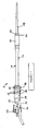
- Fig. 1 shows a piezoelectric transducer 8 in a straight or unbent form
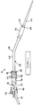
- Fig. 2 shows another transducer 10 in an angled or bent form
- the transducer of Fig. 1 includes a stack of piezoelectric crystals 12 having a front driver 14 consisting in part of a rod 16 and a transformer mass 18 for amplifying the longitudinal motion generated by the piezoelectric crystals 12.
- the transducer of Fig. 2 likewise comprises a stack of piezoelectric crystals 20 and a front driver 22 including a rod or shaft 24 and a motion-amplification mass 26.
- Rod or shaft 24 is formed with a bend 28.
- Front drivers 14 and 22 are constructed of materials with high acoustic efficiency such as titanium, although other materials might be envisioned. Each driver 14 and 22 is hollow in that a bore (not shown) is provided throughout which will become the aspirant passageway when the unit is fully assembled.
- the crystals 12 and 20 are of man made materials such as Lead Zirconate Titanate (PZT) composites shaped into a ring configuration.
- Crystals 12 surround a hollow stud 30 which projects rearwardly, i.e., in a proximal direction, from front driver 14, while crystals 20 surround a hollow stud 32 which projects in a rearward or proximal direction from front driver 22.
- Transducers 8 and 10 further include respective rear drivers 34 and 36 each of which is a two piece construction of tungsten and titanium.
- Each transducer device 8 and 10 is configured as a Langevin Sandwich type transducer wherein the crystals 12 or 20 with electrodes 38 or 40 are subjected to compression by tightening the rear driver 34 or 36 via internal threads to the stud 30 or 32 of front driver 14 or 22 at a predetermined torque or prestress level. By connecting the electrodes 38 or 40 electrically in parallel, the transducer 8 or 10 may be set to vibrate when an alternating signal is applied to the positive and negative connections.
- studs 30 and 32 of front drivers 14 and 22 are each elongated, for instance, to a length of 7,34 cm ⁇ 0,25 cm (2.888 inch ⁇ 0.100 inch), from a crystal distal face 42, 44 and terminate at the proximal end in a respective threaded element 46, 48 which has thread of the same size of that of the respective rear driver 34, 36, to allow assembly of the crystal section. Studs 30 and 32 have shanks 50 and 52 of reduced wall thickness to provide decoupling of the vibrations from the respective crystal stack 12 and 20 to a rear element, for instance, a casing end cap.
- studs 30, 32 are threaded and sealed into a respective rear damping mass 54, 56 that because of materials used (stainless steel, titanium tungsten) and the volume provided has a relatively significant inertia that dampens any vibrations resulting from the transducer 8, 10 and prevents transmission to the case and liquid passageway.
- the threaded element 46, 48 at the proximal end of the stud 30, 32 must mate to the female thread of the inertial or damping mass 54, 56 in a tight, interference fit.
- the damping mass 54, 56 must be counter bored to accept the internal threads.
- the internal threads must terminate a certain distance, for instance, approximately 0,16 cm (0.062 inch), from the bottom of the counter bore, depending on the size and power of the transducer, as well as on the characteristic operating frequency.
- the damping mass 54, 56 is threaded onto the threaded element 46, 48 until the stud threads bottom. Then the damping mass 54, 56 is subjected to an additional torque until the stud end and the counter bore ends mate. In this way, a fluid tight passageway is formed and the metal parts act as a single piece. Any other means such as a lower torque or sealants do not provide the coupling required to eliminate transverse vibrations and early transducer failure.
- Each front driver 14, 22 is connected at a distal side of the respective motion-amplification mass or gain stage 18, 26 to a horn or probe 58, 60.
- the overall length of the assembly of transducer 8, 10 and probe 58, 60 corresponds to one full wavelength of the desired operating frequency, although integer multiples of the half wavelength greater than or equal to two (one full wave) could be envisioned.
- Probe 58, 60 is connected to transducer 8, 10 and particular motion-amplification mass 18, 26 via a nut 62, 64 and a washer 66, 68 at a frequency node point, as is the current state of the art for ultrasonic neuro-aspirators of this type. It can be envisioned that with redesign of the probe 58, 60, the connection could be made at an antinode as well.
- probe 58, 60 provides a gain such that the distal tip amplitudes approach 400 ⁇ m.
- Bend 28 of transducer 10 is 6,25 cm (2.46 inches) from the crystal stack distal face 44. This dimension depends upon the gain ratio of front driver 22 and may vary for different diameters and frequencies.
- the radius of curvature of rod 24 at bend 28 is 1,27 cm (1 ⁇ 2") which again was found to be fairly sensitive. If the bend radius is 1 inch, for instance, significant transverse vibrations were present at the rear mass. Smaller radii stressed the metal to the point of tearing or fracture. When constructed in this form, transducer 10 provided an angle of curvature of 20°.
- front driver rod or shaft 24 has been found to be optimal between 0,58 cm (0.230 inch) maximum and 0,52 cm (0.205 inch) minimum in order for the shaft to provide isolation for longitudinal as well as transverse vibrations to the rear case.
- rear inertial mass 56 is shaped to act as a rear cover for a transducer case 70 ( Fig. 3 )
- a plastic housing member 72 of the transducer case may be placed over the distal end of the transducer 10 until its proximal end mates to a locating boss 74 ( Figs. 2-4 ) of inertial mass 56.
- O-rings 76 or a sealant By sealing the interface with known means such as O-rings 76 or a sealant, a gas tight and liquid tight seal is made which allows the unit to be autoclaved.
- a front nodal ring 78 of the transducer 10 is likewise sealed by an O-ring 79.
- Case 70 so formed can be grasped and manipulated by a surgeon to project the tip of the probe 60 against unwanted tissue at a surgical site in a patient. Since the case 70 only touches the rear inertial mass 56 and the front nodal ring 78 of the transducer 10, no vibrations are coupled to the case itself, fulfilling one on the important elements of the design.
- rear inertial mass 54, 56 includes a ramped ridge 80, as illustrated in Figs. 5 and 6 .
- An inner surface of a plastic or polymeric case member 82 has a corresponding internal protrusion 84.
- the case protrusion 84 contacts the ramped or inclined side (not separately labeled) of the ridge 80.
- the plastic case member 82 expands slightly to allow the protrusion 84 to snap over the ramped ridge 80.
- liquid In all surgical aspirators of this type, liquid must be supplied to the operating site.
- This liquid is generally sterile saline but this is not critical to the invention.
- the liquid serves to cool the probe, provide irrigation and cooling of the tissues and provides a liquid into which the tissue may be disrupted, emulsified and subsequently aspirated.
- the necessary fluid pathway is provided by a sheath made of silicone or another elastomer, which surrounds the probe and provides a coaxial pathway for the fluid.
- case 70 of the present surgical instrument assembly includes housing member 72 and another hard polymeric case member 73. Housing member 72 and case member 73 are rigidly connected to one another and may be considered a single rigid case member. As further depicted in Fig. 3 , case 70 additionally includes a hard plastic case extender or sheath 86 which mates to the transducer case member 73, 82 via a flexible connector or coupling 88. This allows the hard plastic sheath 86 to be placed over the probe 60 (after attaching to the transducer 10 via a threaded joint) and snapped onto the case members 70, 82 providing a liquid tight seal. This is an improvement over prior art which required a one piece banana shaped plastic case which was a clam shell configuration and was difficult to seal and make robust against damage from handling and dropping. The flexible coupling 88 and sheath 86 thus provide significant benefits.
- a silicon flue 90 is then placed over the probe 60 and snapped onto the distal end of the plastic extender 86 in a standard manner.
- the entire assembly constitutes an improvement over prior art in that a long silicone sheath has been used in the past. When the surgeon grasped the flexible sheath, ultrasonic energy could be coupled to the hand, inducing discomfort.
- a fluid barb or port element 92 ( Fig. 3 ) is placed into the transducer case members 70, 82 near its distal end.
- the barb 92 communicates with the interior of the case members 70, 82.
- a flexible liquid tube (not shown) is placed onto the barb 92, liquid may be pumped into the interior cavity formed by the case members 70, 82 and the front driver nodal ring 78. Liquid will then be forced to travel distally through the annular passageway formed by the transducer front driver 22, the transducer case members 70, 82, the probe 60 and the silicon flue 90.
- the only outlet then is the proximal end of the flue 90 that is in close proximity to the probe distal end.
- the liquid will then flood the area around the probe and provide the advantages described herein.
- vent hole 94 spaced proximally from the fluid barb 92.
- This vent hole 94 allows air to flow into the interior space of case member 70, 82. It was found that when this vent is not provided, fluid is held in the cavity when the pump stops running, due to a vacuum being developed above the liquid level, similar to that of a gravity type water cooler. With the bleed hole provided, the vacuum is relieved and liquid flows due to gravity. The benefit is that the liquid does not back up into the area around the nodal ring which, if left there, increases the load on the system and consequently reduces the efficiency of the device. It also leads to premature product failure since the cavitation erosion caused by the ultrasonic energy in such fluid wears the metal away. For the reasons given, the vent hole should be located at the top of the transducer, as shown in Fig. 3 .
- a splined ring 96 is provided that serves to locate the hard sheath 86 concentrically around the front driver 22.
- This ring 96 is made from a hard elastomer or polytetrafluorethylene which is pressed into sheath 86 or is otherwise fixedly located within it by known means.
- the ring 96 not only keeps the sheath 86 concentric with the front driver 22, it was found to suppress the transverse vibrations throughout the assembly.
- Splines 98 of ring 96 allow for liquid passage down to the distal end. In practice the internal diameter of the ring 96 is a sliding fit against the front driver 22.
- damping mass 56 is 13 grams (0.46 ounce)
- shank 52 of stud 34 has a wall thickness of 0,04 cm (0.017 inch) and inner and outer diameters of 0,20 cm (0.078 inch) and 0,28 cm (0.112 inch), respectively
- rod or shaft 24 has a diameter of 0,55 cm (0.215 inch)
- the design operating frequency is about 23 kHz.
- This transducer has been shown to be an effective tool when used to ablate unwanted tissue within the body.
- the efficiency of the transducer is very high in that it can provide over 70 watts of power for extended periods without a significant temperature rise while providing 400 ⁇ m or more at the tips distal end.
- the overall diameter is 2,0 cm (0.800").
- the feeding of liquid is not necessary to reduce vibrations.
- the instrument may be operated without liquid until heat generated at the joint between front driver 22 and probe 60 requires the liquid for cooling purposes.
- Reference designation 99 in Figs. 3-6 represents an electrical cable. Individual cable wires (not illustrated) are connected to electrodes 40.
- the inertial mass to which the proximally extending transducer stud is connected need not be an end cap of the transducer casing. Instead, the inertial mass may be a separate element located distally of the proximal end cap of the casing.
- the coupling of the proximal ends of studs 30, 32 to inertial or damping mass 54, 56 may be accomplished by other means such as welding, which ensures that the studs and the damping mass cofunction as an integral or unitary piece. Accordingly, it is to be understood that the drawings and descriptions herein are proffered by way of example to facilitate comprehension of the invention and should not be construed to limit the scope thereof.
Abstract
Description
- This invention relates to a high efficiency medical surgical transducer with an ergonomically enhanced shape. More particularly, this invention relates to a device that will transform electrical signals to mechanical vibrations to allow for ablation of tumors and other unwanted body tissues while allowing line of sight visualization of the operative sight by the surgeon.
- Over the past 30 years, several ultrasonic tools have been invented which can be used to ablate or cut tissue in surgery. Such devices are disclosed by
Wuchinich et al. in U.S. Patent No. 4223,676 andIdemoto et al in U.S. Patent No. 5,188,102 . - In practice, these surgical devices include a blunt tip hollow probe that vibrates at frequencies between 20 kHz and 100 kHz, with amplitudes up to 300 µm or more. Such devices ablate tissue by either producing cavitation bubbles which implode and disrupt cells, tissue compression and relaxation stresses (sometimes called the jackhammer effect) or by other forces such as micro streaming of bubbles in the tissue matrix. The effect is that the tissue becomes liquefied and separated. It then becomes emulsified with the irrigant solution. The resulting emulsion is then aspirated from the site. Bulk excision of tissue is possible by applying the energy around and under unwanted tumors to separate it from the surrounding structure. The surgeon can then lift the tissue out using common tools such as forceps.
- The probe or tube is excited by a transducer of either the piezoelectric or magnetostrictive type that transforms an alternating electrical signal within the frequencies indicated into a longitudinal or transverse vibration. When the probe is attached to the transducer, the two become a single element with series and parallel resonances. The designer will try to tailor the mechanical and electrical characteristics of these elements to provide the proper frequency of operation. Most of the time, the elements will have a long axis that is straight, as shown in
Fig 1 . This is done for simplicity and economic considerations. In almost all applications, whether medical or industrial, such an embodiment is practical and useful. However, in applications such as open field brain surgery, such an embodiment is impractical since the doctor is using a microscope while operating, to enlarge the view of the delicate structures of the brain. Here, the length of the transducer/horn combination may be disadvantageous, since the proximal end of the transducer will contact the microscope head and interfere with the ability of the surgeon to manipulate the tool for maximum efficacy. As important, the transducer housing major diameter interferes with the surgeon's field of view of the operative site. - In the past, several inventors have attempted to solve the problem by kinking or bending the transducer or probe element to provide an angled handpiece. With this method, the surgeon handles the distal end of the combination normally while the transducer lies along his or her hand, away from the microscope head and thereby increasing the ability to visualize the operative field.
Fig. 2 shows an ultrasonic transducer and probe assembly with a kink or a bend in the front driver of the transducer assembly. - Several factors have limited the benefit of a bent transducer or probe. One is the fact that the bend introduces a vector force that manifests itself as a transverse or bending wave motion. This motion reduces the efficiency of the tip action and increases the energy loss in the transducer itself. As a result, the transducer temperature rises, causing the surface to become too hot to touch. Also, the transverse vibrations lead to large stresses in the vibratory elements which at higher amplitudes cause metal fatigue and probe fracture. The transverse vector increases in direct proportion to the angle of curvature. Because of these design problems, the designer will both limit the bend angle as well as reduce the maximum tip amplitude at which the device will be allowed to vibrate. As an example, one commercially available device gives a maximum amplitude for a straight transducer probe combination as 355 µm while offering a transducer with a 10° angle for the same purpose at only 183 µm, or almost 50% less. Both remedies reduce the efficacy of the operative procedure in that the harder, denser tumors require higher amplitudes and more power to ablate and remove. In addition, the small bend angle still allows the transducer proximal end to contact the microscopes in practice.
- The diameter of the transducer body is also a factor in the ergonomics of the device. The larger the unit, the heavier and more difficult it is to manipulate. When poled, most surgeons requested a device that is the size of a large writing pen. Since the electrical power required to ablate tissue and overcome the electromechanical losses in the handpiece is up to 70 watts, making a thinner handpiece that does not get hot during use is problematic due to the fact the crystal mass in a piezoelectric handpiece is reduced. The power density will then rise, increasing power loss and waste heat generation. Similar problems exist for magnetostrictive devices, although these can generally be thinner for given wattage output. However, since magnetostrictive devices cannot easily accommodate a central aspiration port (one that is concentric with the long axis) tissue blockage can occur when aspirating tissue. This is a major detriment.
- Other factors, which are desirable in a practical embodiment, would be a fluid passageway with no joints within the transducer case to prevent liquid leakage into the interior of the transducer that would cause failure of the electrical components. In addition, the case of the unit should be isolated from the vibrations of the probe and transducer itself. If the case vibrated in sympathy with the transducer, the surgeon would feel the vibrations in his or her hand. This leads to less tactile feedback during the operation, fatigue and could in fact lead to damage of the hand upon long exposure.
-
U.S. Patent No. 5,371,429 discloses an electromechanical transducer device according to the first part of claim 1, including means for acoustically decoupling the casing and the wave transmission member from one another. -
U.S. Patent No. 6,051,010 discloses a system for attaching ultrasonic transmission components together without using a separate torque limiting device. -
U.S. Patent No. 5,397,293 discloses an ultrasonic device provided with a sheath and transverse motion damping. -
U.S. Patent No. 4,741,731 discloses a vented ultrasonic transducer for a surgical handpiece. - The present invention is defined in claim 1 and aims to provide an improved ultrasonic surgical instrument that may be used in conjunction with microscopes. The improved ultrasonic surgical instrument has a piezoelectric transducer that has an effective angle of curvature greater than 10 and a concentric central flow with no internal fluid passage joints which may leak and cause product failure. In this improved ultrasonic surgical instrument tool vibrations are isolated from the transducer case.
- The handpiece may have a diameter of less than about 2,54 cm (one inch).
- A transducer assembly for an ultrasonic surgical instrument comprises, in accordance with the present invention, a front driver having an elongate shaft extending in one direction and a stud extending in an opposite direction. An electromechanical transducer element (for instance, a plurality of piezoelectric crystal disks) is disposed around the stud. The transducer assembly also comprises a rear driver disposed around the stud on a side of the electromechanical transducer element opposite the front driver, the electromechanical transducer element being clamped between the front driver and the rear driver. An inertial or damping mass is fixedly connected to the stud at a point spaced from the rear driver.
- Pursuant to a preferred feature of the present invention, the inertial or damping mass is an end cap of a transducer case. However, it is alternatively possible for the inertial or damping mass to be located inside a case, rather than being part of the case. Where the inertial or damping mass is an end cap, it may be connected to a substantially rigid case member in a snap-lock fit.
- The fixed interconnection of the stud and the inertial or damping mass may be effectuated as an interference fit of an externally threaded end element of the stud in an internally threaded counter bore in the inertial or damping mass. The inertial or damping mass is preferably torqued onto the threaded end element until an end thereof and an end of the counter bore mate.
- Pursuant to a particularly preferred embodiment of the present invention, the stud projects a distance of between 6,4 and 8,3 cm (2.50 and 3.25 inches) from a front face of the electromechanical transducer. More particularly, the stud projects a distance of between (6,9 and 7,6 cm (2.7 and 3.0 inches) from the front face of the electromechanical transducer. In addition to a uniquely long length, the stud is formed with an especially thin wall, for instance, with a thickness between approximately 0,03 and 0,64 cm (0.010 and 0.25 inch). The thin wall and the length of the stud enable the stud to function as a flexible element in damping vibrations of the electromechanical transducer.
- Where the elongate shaft of the front driver is curved at a bend region to form a first portion coaxial with the stud and a second portion at an angle with respect to the stud, the transducer assembly further comprises a first substantially rigid case member disposed about the electromechanical transducer element and the first portion of the elongate shaft, a second substantially rigid case member disposed about the second portion of the elongate shaft, and a flexible coupling member disposed about the elongate shaft at the bend region. The flexible coupling member is connected on one side to the first substantially rigid case member and on an opposite side to the second substantially rigid case member.
- According to a further preferred feature of the invention, a splined ring is disposed between the second substantially rigid case member and the second portion of the shaft. Where the second portion of the elongate shaft is formed with an enlarged amplification mass, the splined ring is disposed in engagement with the mass.
- According to yet another preferred embodiment of the present invention, the first substantially rigid case member is provided with a barb or port element and a vent hole. The vent hold is spaced in a proximal direction from the barb or port element and is located on a same side of the first substantially rigid case member as the barb or port element.
- A method of manufacturing is also described wherein a transducer for an ultrasonic medical device utilizes a front driver with a rearwardly extending stud having an externally threaded free end. A threaded counter bore is formed in a damping mass so that internal threads of the counter bore terminate a predetermined distance from a bottom of the counter bore. The damping mass is threaded onto the threaded free end of the stud until the stud threads bottom. The damping mass is subjected then to an additional torque until the stud free end and a counter bore end mate.
-
-
Fig. 1 is partially a side elevational view and partially a cross-sectional view of a transducer in accordance with the present invention, showing an attached ultrasonic horn or probe. -
Fig. 2 is partially a side elevational view and partially a cross-sectional view of another transducer in accordance with the present invention, showing an attached horn or probe. -
Fig. 3 is a side elevational view of the transducer and probe ofFig. 2 and a cross-sectional view of a casing and sheath assembly in accordance with the present invention. -
Fig. 4 is a cross-sectional view, on a larger scale, of an inertial mass end cap with couplings shown inFigs. 2 and3 , in accordance with the present invention. -
Fig. 5 is a cross-sectional view, on the scale ofFig. 4 , of an alternative end cap in accordance with the present invention. - A piezoelectric transducer is disclosed herein which incorporates a plurality of features which in concert exhibit features desirable in the performance of delicate medical operations. In addition, the various features may have utility in and of themselves in different applications. The terminology used in discussing the transducer, an associated instrument assembly, and a method of manufacture will be that generally accepted in the art of ultrasound engineering. The term "fixedly connected" when used herein to describe the coupling of a stud to an inertial or damping mass refers to a connection which is such that the stud and the inertial or damping mass were fabricated as a single or unitary object. Thus, the connection is rigid and essentially irreversible.
-
Fig. 1 shows apiezoelectric transducer 8 in a straight or unbent form, whileFig. 2 shows anothertransducer 10 in an angled or bent form. The transducer ofFig. 1 includes a stack ofpiezoelectric crystals 12 having afront driver 14 consisting in part of arod 16 and atransformer mass 18 for amplifying the longitudinal motion generated by thepiezoelectric crystals 12. The transducer ofFig. 2 likewise comprises a stack ofpiezoelectric crystals 20 and afront driver 22 including a rod orshaft 24 and a motion-amplification mass 26. Rod orshaft 24 is formed with abend 28. -
Front drivers driver crystals -
Crystals 12 surround ahollow stud 30 which projects rearwardly, i.e., in a proximal direction, fromfront driver 14, whilecrystals 20 surround ahollow stud 32 which projects in a rearward or proximal direction fromfront driver 22.Transducers rear drivers transducer device crystals electrodes rear driver stud front driver electrodes transducer - An improvement over prior art is that
studs front drivers distal face element rear driver Studs shanks respective crystal stack stud shank rear driver studs rear damping mass transducer element stud mass mass mass element mass - Each
front driver stage probe transducer probe Probe transducer amplification mass nut washer probe stage probe -
Bend 28 oftransducer 10 is 6,25 cm (2.46 inches) from the crystal stackdistal face 44. This dimension depends upon the gain ratio offront driver 22 and may vary for different diameters and frequencies. The radius of curvature ofrod 24 atbend 28 is 1,27 cm (½") which again was found to be fairly sensitive. If the bend radius is 1 inch, for instance, significant transverse vibrations were present at the rear mass. Smaller radii stressed the metal to the point of tearing or fracture. When constructed in this form,transducer 10 provided an angle of curvature of 20°. - The diameter of front driver rod or
shaft 24 has been found to be optimal between 0,58 cm (0.230 inch) maximum and 0,52 cm (0.205 inch) minimum in order for the shaft to provide isolation for longitudinal as well as transverse vibrations to the rear case. Where rearinertial mass 56 is shaped to act as a rear cover for a transducer case 70 (Fig. 3 ), aplastic housing member 72 of the transducer case may be placed over the distal end of thetransducer 10 until its proximal end mates to a locating boss 74 (Figs. 2-4 ) ofinertial mass 56. By sealing the interface with known means such as O-rings 76 or a sealant, a gas tight and liquid tight seal is made which allows the unit to be autoclaved. A frontnodal ring 78 of thetransducer 10 is likewise sealed by an O-ring 79.Case 70 so formed can be grasped and manipulated by a surgeon to project the tip of theprobe 60 against unwanted tissue at a surgical site in a patient. Since thecase 70 only touches the rearinertial mass 56 and the frontnodal ring 78 of thetransducer 10, no vibrations are coupled to the case itself, fulfilling one on the important elements of the design. - One modification which provides ease of assembly as well as reduction of parts count since fasteners are not needed is a snap fit assembly. Here rear
inertial mass ridge 80, as illustrated inFigs. 5 and 6 . An inner surface of a plastic orpolymeric case member 82 has a correspondinginternal protrusion 84. When thecase member 82 is slid over the rearinertial mass 56, thecase protrusion 84 contacts the ramped or inclined side (not separately labeled) of theridge 80. As more force is applied, theplastic case member 82 expands slightly to allow theprotrusion 84 to snap over the rampedridge 80. Since the proximal side (not separately labeled) of theridge 80 is perpendicular to theboss 74, thecase member 82 is effectively trapped. If sealant or O-rings are provided the assembly is essentially complete without the need for locking rings, screws or other fastening means. - In constructing the embodiment, several other inventions of note were developed to complete the assembly.
- In all surgical aspirators of this type, liquid must be supplied to the operating site. This liquid is generally sterile saline but this is not critical to the invention. The liquid serves to cool the probe, provide irrigation and cooling of the tissues and provides a liquid into which the tissue may be disrupted, emulsified and subsequently aspirated. In several prior art designs, the necessary fluid pathway is provided by a sheath made of silicone or another elastomer, which surrounds the probe and provides a coaxial pathway for the fluid.
- As depicted in
Fig. 3 ,case 70 of the present surgical instrument assembly includeshousing member 72 and another hard polymeric case member 73.Housing member 72 and case member 73 are rigidly connected to one another and may be considered a single rigid case member. As further depicted inFig. 3 ,case 70 additionally includes a hard plastic case extender orsheath 86 which mates to thetransducer case member 73, 82 via a flexible connector orcoupling 88. This allows thehard plastic sheath 86 to be placed over the probe 60 (after attaching to thetransducer 10 via a threaded joint) and snapped onto thecase members flexible coupling 88 andsheath 86 thus provide significant benefits. - A
silicon flue 90 is then placed over theprobe 60 and snapped onto the distal end of theplastic extender 86 in a standard manner. The entire assembly constitutes an improvement over prior art in that a long silicone sheath has been used in the past. When the surgeon grasped the flexible sheath, ultrasonic energy could be coupled to the hand, inducing discomfort. - A fluid barb or port element 92 (
Fig. 3 ) is placed into thetransducer case members barb 92 communicates with the interior of thecase members barb 92, liquid may be pumped into the interior cavity formed by thecase members nodal ring 78. Liquid will then be forced to travel distally through the annular passageway formed by thetransducer front driver 22, thetransducer case members probe 60 and thesilicon flue 90. The only outlet then is the proximal end of theflue 90 that is in close proximity to the probe distal end. The liquid will then flood the area around the probe and provide the advantages described herein. - Further improvement is the inclusion of a
vent hole 94 spaced proximally from thefluid barb 92. Thisvent hole 94 allows air to flow into the interior space ofcase member Fig. 3 . - As illustrated in
Fig. 3 , asplined ring 96 is provided that serves to locate thehard sheath 86 concentrically around thefront driver 22. Thisring 96 is made from a hard elastomer or polytetrafluorethylene which is pressed intosheath 86 or is otherwise fixedly located within it by known means. Thering 96 not only keeps thesheath 86 concentric with thefront driver 22, it was found to suppress the transverse vibrations throughout the assembly.Splines 98 ofring 96 allow for liquid passage down to the distal end. In practice the internal diameter of thering 96 is a sliding fit against thefront driver 22. - In one example of transducer 10 (
Fig. 3 ) described herein, dampingmass 56 is 13 grams (0.46 ounce),shank 52 ofstud 34 has a wall thickness of 0,04 cm (0.017 inch) and inner and outer diameters of 0,20 cm (0.078 inch) and 0,28 cm (0.112 inch), respectively, rod orshaft 24 has a diameter of 0,55 cm (0.215 inch), and the design operating frequency is about 23 kHz. This transducer has been shown to be an effective tool when used to ablate unwanted tissue within the body. The efficiency of the transducer is very high in that it can provide over 70 watts of power for extended periods without a significant temperature rise while providing 400 µm or more at the tips distal end. The overall diameter is 2,0 cm (0.800"). In all, it effectively provides all of the desired features for a device of this type. For example, as an indication of how the design suppresses transverse vibrations, the feeding of liquid is not necessary to reduce vibrations. The instrument may be operated without liquid until heat generated at the joint betweenfront driver 22 andprobe 60 requires the liquid for cooling purposes. -
Reference designation 99 inFigs. 3-6 represents an electrical cable. Individual cable wires (not illustrated) are connected toelectrodes 40. - Although the invention has been described in terms of particular embodiments and applications, one of ordinary skill in the art, in light of this teaching, can generate additional embodiments and modifications without departing from the scope of the claimed invention. It is to be noted, for instance, that the inertial mass to which the proximally extending transducer stud is connected need not be an end cap of the transducer casing. Instead, the inertial mass may be a separate element located distally of the proximal end cap of the casing. In addition, the coupling of the proximal ends of
studs mass
Claims (14)
- A transducer assembly for an ultrasonic surgical instrument, comprising:a front driver (14, 22) having an elongate shaft (16, 24) extending in one direction and a stud (30, 32) extending in an opposite direction;an electromechanical transducer element (12, 20) disposed around said stud (30, 32);a rear driver (34, 36) disposed around said stud (30, 32) on a side of said electromechanical transducer element (12, 20) opposite said front driver (14, 22), said electromechanical transducer element (12, 20) being clamped between said front driver (14, 22) and said rear driver (34, 36); andan inertial or damping mass (54, 56) connected to said stud (30, 32) at a point spaced from said rear driver (34, 36) characterised in that said inertial or damping mass (54, 56) is fixedly or rigidly connected to said stud (30, 32) by threads or by welding so that said stud (30, 32) and said inertial or damping mass (54, 56) are effectively a single or unitary object to thereby eliminate transverse vibrations and easly tranducer failure.
- The transducer assembly according to claim 1 characterized in that said inertial or damping mass (54, 56) is an end cap of a transducer case.
- The transducer assembly according to claim 2 characterized in that said casing includes a substantially rigid case member (70, 73, 82) locked to said end cap in a snap-lock fit.
- The transducer assembly according to claim 1 characterized in that said stud (30, 32) is provided with an externally threaded end element (46, 48), said inertial or damping mass being provided with an internally threaded counter bore, said threaded end element being inserted into said counter bore in an interference fit.
- The transducer assembly according to claim 4 characterized in that said inertial or damping mass is torqued onto said threaded end element (46, 48) until an end thereof and an end of said counter bore mate.
- The transducer assembly according to claim 1 characterized in that said stud (30, 32) projects a distance of between 6,4 and 8,3 cm (2.50 and 3.25 inches) from a front face (42, 44) of said electromechanical transducer element.
- The transducer assembly according to claim 6 characterized in that said stud (30, 32) projects a distance of between 6,9 and 7,8 cm (2.7 and 3.0 inches) from said front face (42, 44) of said electromechanical transducer element.
- The transducer assembly according to claim 1 characterized in that said stud (30, 32) has a wall of a thickness sufficiently small to enable said stud (30, 32) to function as a flexible element in damping vibrations of said electromechanical transducer element (12, 20).
- The transducer assembly according to claim 8 characterized in that said stud has a wall thickness between approximately 0,03 and 0,64 cm (0.010 and 0.25 inch).
- The transducer assembly according to claim 1 characterized in that said elongate shaft (16, 24) of said front driver (22) is curved at a bend region to form a first portion coaxial with said stud and a second portion at an angle with respect to said stud, said first portion and said second portion being substantially rigid with one another, further comprising:a first substantially rigid case member (70, 82) disposed about said electromechanical transducer element and said first portion of said elongate shaft;a second substantially rigid case member (86) disposed about said second portion of said elongate shaft; anda flexible coupling member (88) disposed about said elongate shaft at said bend region, said flexible coupling member being connected on one side to said first substantially rigid case member and on an opposite side to said second substantially rigid case member.
- The transducer assembly according to claim 10 characterized in that a splined ring (96) is disposed between said second substantially rigid case member and said second portion of said shaft.
- The transducer assembly according to claim 11 characterized in that said second portion (26) of said elongate shaft is formed with an enlarged amplification mass (26), said splined ring being disposed in engagement with said amplification mass.
- The transducer assembly according to claim 10 characterized in that said first substantially rigid case member (70, 82) is provided with a barb or port element (92) and a vent hole (94).
- The transducer assembly according to claim 13 characterized in that said vent hole (94) is spaced in a proximal direction from said barb or port element (92) and is located on a same side of said first substantially rigid case member (70, 82) as said barb or port element.
Applications Claiming Priority (3)
| Application Number | Priority Date | Filing Date | Title |
|---|---|---|---|
| US37036402P | 2002-04-05 | 2002-04-05 | |
| US370364P | 2002-04-05 | ||
| PCT/US2003/009586 WO2003092793A2 (en) | 2002-04-05 | 2003-04-01 | Electromechanical transducer with ergonomic shape |
Publications (3)
| Publication Number | Publication Date |
|---|---|
| EP1492592A2 EP1492592A2 (en) | 2005-01-05 |
| EP1492592A4 EP1492592A4 (en) | 2008-02-27 |
| EP1492592B1 true EP1492592B1 (en) | 2010-12-08 |
Family
ID=29401297
Family Applications (1)
| Application Number | Title | Priority Date | Filing Date |
|---|---|---|---|
| EP03747575A Expired - Lifetime EP1492592B1 (en) | 2002-04-05 | 2003-04-01 | High efficiency medical transducer with ergonomic shape and method of manufacture |
Country Status (8)
| Country | Link |
|---|---|
| US (1) | US7442168B2 (en) |
| EP (1) | EP1492592B1 (en) |
| JP (2) | JP4429160B2 (en) |
| AU (1) | AU2003265111A1 (en) |
| CA (1) | CA2480773C (en) |
| DE (1) | DE60335251D1 (en) |
| ES (1) | ES2355815T3 (en) |
| WO (1) | WO2003092793A2 (en) |
Families Citing this family (68)
| Publication number | Priority date | Publication date | Assignee | Title |
|---|---|---|---|---|
| US8182501B2 (en) | 2004-02-27 | 2012-05-22 | Ethicon Endo-Surgery, Inc. | Ultrasonic surgical shears and method for sealing a blood vessel using same |
| EP3162309B1 (en) | 2004-10-08 | 2022-10-26 | Ethicon LLC | Ultrasonic surgical instrument |
| ITBO20050097A1 (en) * | 2005-02-24 | 2006-08-25 | Italia Medica S R L | HANDPIECE FOR ULTRASOUND ELETROMEDICAL EQUIPMENT |
| US8057408B2 (en) | 2005-09-22 | 2011-11-15 | The Regents Of The University Of Michigan | Pulsed cavitational ultrasound therapy |
| US10219815B2 (en) | 2005-09-22 | 2019-03-05 | The Regents Of The University Of Michigan | Histotripsy for thrombolysis |
| US8152825B2 (en) * | 2005-10-14 | 2012-04-10 | Ethicon Endo-Surgery, Inc. | Medical ultrasound system and handpiece and methods for making and tuning |
| US20070191713A1 (en) | 2005-10-14 | 2007-08-16 | Eichmann Stephen E | Ultrasonic device for cutting and coagulating |
| US7621930B2 (en) | 2006-01-20 | 2009-11-24 | Ethicon Endo-Surgery, Inc. | Ultrasound medical instrument having a medical ultrasonic blade |
| US8911460B2 (en) | 2007-03-22 | 2014-12-16 | Ethicon Endo-Surgery, Inc. | Ultrasonic surgical instruments |
| US8142461B2 (en) | 2007-03-22 | 2012-03-27 | Ethicon Endo-Surgery, Inc. | Surgical instruments |
| US8057498B2 (en) | 2007-11-30 | 2011-11-15 | Ethicon Endo-Surgery, Inc. | Ultrasonic surgical instrument blades |
| US8808319B2 (en) | 2007-07-27 | 2014-08-19 | Ethicon Endo-Surgery, Inc. | Surgical instruments |
| US8523889B2 (en) | 2007-07-27 | 2013-09-03 | Ethicon Endo-Surgery, Inc. | Ultrasonic end effectors with increased active length |
| US8512365B2 (en) | 2007-07-31 | 2013-08-20 | Ethicon Endo-Surgery, Inc. | Surgical instruments |
| US9044261B2 (en) | 2007-07-31 | 2015-06-02 | Ethicon Endo-Surgery, Inc. | Temperature controlled ultrasonic surgical instruments |
| US8430898B2 (en) | 2007-07-31 | 2013-04-30 | Ethicon Endo-Surgery, Inc. | Ultrasonic surgical instruments |
| EP2796102B1 (en) | 2007-10-05 | 2018-03-14 | Ethicon LLC | Ergonomic surgical instruments |
| AU2008310869B2 (en) * | 2007-10-10 | 2014-04-17 | Ethicon Endo-Surgery, Inc | Ultrasonic device for cutting and coagulating |
| US10010339B2 (en) | 2007-11-30 | 2018-07-03 | Ethicon Llc | Ultrasonic surgical blades |
| US9700339B2 (en) | 2009-05-20 | 2017-07-11 | Ethicon Endo-Surgery, Inc. | Coupling arrangements and methods for attaching tools to ultrasonic surgical instruments |
| US8334635B2 (en) * | 2009-06-24 | 2012-12-18 | Ethicon Endo-Surgery, Inc. | Transducer arrangements for ultrasonic surgical instruments |
| CA2770452C (en) | 2009-08-17 | 2017-09-19 | Histosonics, Inc. | Disposable acoustic coupling medium container |
| CA2770706C (en) | 2009-08-26 | 2017-06-20 | Charles A. Cain | Devices and methods for using controlled bubble cloud cavitation in fractionating urinary stones |
| JP5863654B2 (en) | 2009-08-26 | 2016-02-16 | リージェンツ オブ ザ ユニバーシティー オブ ミシガン | Micromanipulator control arm for therapeutic and image processing ultrasonic transducers |
| US8539813B2 (en) | 2009-09-22 | 2013-09-24 | The Regents Of The University Of Michigan | Gel phantoms for testing cavitational ultrasound (histotripsy) transducers |
| US8486096B2 (en) | 2010-02-11 | 2013-07-16 | Ethicon Endo-Surgery, Inc. | Dual purpose surgical instrument for cutting and coagulating tissue |
| US8951272B2 (en) | 2010-02-11 | 2015-02-10 | Ethicon Endo-Surgery, Inc. | Seal arrangements for ultrasonically powered surgical instruments |
| US8958270B2 (en) * | 2010-07-07 | 2015-02-17 | California Institute Of Technology | Monolithic flexure pre-stressed ultrasonic horns |
| US10420693B2 (en) | 2011-02-23 | 2019-09-24 | Perfuzia Medical, Inc. | Actuator for delivery of vibratory stimulation to an area of the body and method of application |
| US8621946B1 (en) * | 2011-06-08 | 2014-01-07 | Patrick Nefos | Support for ultrasonic probe |
| US9144694B2 (en) | 2011-08-10 | 2015-09-29 | The Regents Of The University Of Michigan | Lesion generation through bone using histotripsy therapy without aberration correction |
| US9049783B2 (en) | 2012-04-13 | 2015-06-02 | Histosonics, Inc. | Systems and methods for obtaining large creepage isolation on printed circuit boards |
| EP2844343B1 (en) | 2012-04-30 | 2018-11-21 | The Regents Of The University Of Michigan | Ultrasound transducer manufacturing using rapid-prototyping method |
| US9820768B2 (en) | 2012-06-29 | 2017-11-21 | Ethicon Llc | Ultrasonic surgical instruments with control mechanisms |
| WO2014055906A1 (en) | 2012-10-05 | 2014-04-10 | The Regents Of The University Of Michigan | Bubble-induced color doppler feedback during histotripsy |
| US10226273B2 (en) | 2013-03-14 | 2019-03-12 | Ethicon Llc | Mechanical fasteners for use with surgical energy devices |
| WO2014150526A1 (en) * | 2013-03-15 | 2014-09-25 | Misonix, Incorporated | Sheath coupling member and associated instrument assembly |
| US10398463B2 (en) * | 2013-06-28 | 2019-09-03 | Misonix Incorporated | Ultrasonic instrument and method for manufacturing same |
| US10182837B2 (en) * | 2013-06-28 | 2019-01-22 | Misonix, Inc. | Sheath coupling member and associated instrument assembly |
| CN105530869B (en) | 2013-07-03 | 2019-10-29 | 希斯托索尼克斯公司 | The histotripsy excitation sequence optimized is formed to bubble cloud using impact scattering |
| US11432900B2 (en) | 2013-07-03 | 2022-09-06 | Histosonics, Inc. | Articulating arm limiter for cavitational ultrasound therapy system |
| US9993843B2 (en) | 2013-07-15 | 2018-06-12 | Dukane Ias, Llc | Adapter for ultrasonic transducer assembly |
| US10780298B2 (en) | 2013-08-22 | 2020-09-22 | The Regents Of The University Of Michigan | Histotripsy using very short monopolar ultrasound pulses |
| GB2521229A (en) | 2013-12-16 | 2015-06-17 | Ethicon Endo Surgery Inc | Medical device |
| CA2960379C (en) * | 2014-09-12 | 2022-12-06 | Mercer Technologies Limited | A sterilisation container, method of sterilisation and sterilisation apparatus |
| BR202015012787U2 (en) * | 2015-05-27 | 2017-05-23 | Tavares De Lima Guimarães Bruno | speech therapy stimulator pen |
| US11020140B2 (en) | 2015-06-17 | 2021-06-01 | Cilag Gmbh International | Ultrasonic surgical blade for use with ultrasonic surgical instruments |
| EP4230262A3 (en) | 2015-06-24 | 2023-11-22 | The Regents Of The University Of Michigan | Histotripsy therapy systems for the treatment of brain tissue |
| US10357303B2 (en) | 2015-06-30 | 2019-07-23 | Ethicon Llc | Translatable outer tube for sealing using shielded lap chole dissector |
| US11173327B2 (en) | 2016-04-25 | 2021-11-16 | Integra Lifesciences Enterprises, Lllp | Flue for ultrasonic aspiration surgical horn |
| USD820441S1 (en) | 2016-06-13 | 2018-06-12 | Integra Lifesciences Nr Ireland Limited | Surgical handpiece nosecone |
| EP3463125B1 (en) | 2016-05-24 | 2022-08-31 | Integra LifeSciences Enterprises, LLLP | Ergonomic tubing attachment for medical apparatus |
| US10245064B2 (en) | 2016-07-12 | 2019-04-02 | Ethicon Llc | Ultrasonic surgical instrument with piezoelectric central lumen transducer |
| US10893883B2 (en) | 2016-07-13 | 2021-01-19 | Ethicon Llc | Ultrasonic assembly for use with ultrasonic surgical instruments |
| US10842522B2 (en) * | 2016-07-15 | 2020-11-24 | Ethicon Llc | Ultrasonic surgical instruments having offset blades |
| US10543012B2 (en) | 2016-08-02 | 2020-01-28 | Misonix, Inc. | Ultrasonic surgical device with reduction in electrical interference |
| USD847990S1 (en) | 2016-08-16 | 2019-05-07 | Ethicon Llc | Surgical instrument |
| US10736649B2 (en) | 2016-08-25 | 2020-08-11 | Ethicon Llc | Electrical and thermal connections for ultrasonic transducer |
| US10952759B2 (en) | 2016-08-25 | 2021-03-23 | Ethicon Llc | Tissue loading of a surgical instrument |
| AU2017362062B2 (en) | 2016-11-16 | 2023-03-23 | Integra Lifesciences Enterprises, Lllp | Ultrasonic surgical handpiece |
| US10687840B1 (en) | 2016-11-17 | 2020-06-23 | Integra Lifesciences Nr Ireland Limited | Ultrasonic transducer tissue selectivity |
| US10603064B2 (en) | 2016-11-28 | 2020-03-31 | Ethicon Llc | Ultrasonic transducer |
| US10820920B2 (en) | 2017-07-05 | 2020-11-03 | Ethicon Llc | Reusable ultrasonic medical devices and methods of their use |
| CA3113964A1 (en) | 2018-09-24 | 2020-04-02 | Stryker Corporation | Ultrasonic surgical handpiece assembly |
| US11918245B2 (en) * | 2018-10-05 | 2024-03-05 | Kogent Surgical, LLC | Ultrasonic surgical handpiece with torsional transducer |
| JP2022510654A (en) | 2018-11-28 | 2022-01-27 | ヒストソニックス,インコーポレーテッド | Tissue disruption system and method |
| US11627981B2 (en) * | 2019-12-20 | 2023-04-18 | Covidien Lp | Ultrasonic transducer assembly and ultrasonic surgical instrument incorporating the same |
| AU2021213168A1 (en) | 2020-01-28 | 2022-09-01 | The Regents Of The University Of Michigan | Systems and methods for histotripsy immunosensitization |
Family Cites Families (17)
| Publication number | Priority date | Publication date | Assignee | Title |
|---|---|---|---|---|
| US4169984A (en) * | 1976-11-30 | 1979-10-02 | Contract Systems Associates, Inc. | Ultrasonic probe |
| US4526571A (en) * | 1982-10-15 | 1985-07-02 | Cooper Lasersonics, Inc. | Curved ultrasonic surgical aspirator |
| US4634419A (en) * | 1985-12-13 | 1987-01-06 | Cooper Lasersonics, Inc. | Angulated ultrasonic surgical handpieces and method for their production |
| US4741731A (en) * | 1986-02-19 | 1988-05-03 | Fibra-Sonics, Inc. | Vented ultrasonic transducer for surgical handpiece |
| JP2660067B2 (en) * | 1989-11-01 | 1997-10-08 | オリンパス光学工業株式会社 | Ultrasound therapy equipment |
| JP2963714B2 (en) * | 1990-02-02 | 1999-10-18 | オリンパス光学工業株式会社 | Ultrasound therapy equipment |
| US5480379A (en) * | 1991-05-22 | 1996-01-02 | La Rosa; Antonio | Ultrasonic dissector and detacher for atherosclerotic plaque and method of using same |
| US5151084A (en) * | 1991-07-29 | 1992-09-29 | Fibra-Sonics, Inc. | Ultrasonic needle with sleeve that includes a baffle |
| US5397293A (en) * | 1992-11-25 | 1995-03-14 | Misonix, Inc. | Ultrasonic device with sheath and transverse motion damping |
| US5312329A (en) * | 1993-04-07 | 1994-05-17 | Valleylab Inc. | Piezo ultrasonic and electrosurgical handpiece |
| US5449370A (en) * | 1993-05-12 | 1995-09-12 | Ethicon, Inc. | Blunt tipped ultrasonic trocar |
| US5371429A (en) * | 1993-09-28 | 1994-12-06 | Misonix, Inc. | Electromechanical transducer device |
| US5628743A (en) * | 1994-12-21 | 1997-05-13 | Valleylab Inc. | Dual mode ultrasonic surgical apparatus |
| US6063098A (en) * | 1996-12-23 | 2000-05-16 | Houser; Kevin | Articulable ultrasonic surgical apparatus |
| US6051010A (en) | 1996-12-23 | 2000-04-18 | Ethicon Endo-Surgery, Inc. | Methods and devices for joining transmission components |
| US5989275A (en) * | 1997-02-28 | 1999-11-23 | Ethicon Endo-Surgery, Inc. | Damping ultrasonic transmission components |
| US5810859A (en) * | 1997-02-28 | 1998-09-22 | Ethicon Endo-Surgery, Inc. | Apparatus for applying torque to an ultrasonic transmission component |
-
2003
- 2003-04-01 EP EP03747575A patent/EP1492592B1/en not_active Expired - Lifetime
- 2003-04-01 ES ES03747575T patent/ES2355815T3/en not_active Expired - Lifetime
- 2003-04-01 AU AU2003265111A patent/AU2003265111A1/en not_active Abandoned
- 2003-04-01 CA CA2480773A patent/CA2480773C/en not_active Expired - Lifetime
- 2003-04-01 US US10/404,374 patent/US7442168B2/en active Active
- 2003-04-01 WO PCT/US2003/009586 patent/WO2003092793A2/en active Application Filing
- 2003-04-01 JP JP2004500974A patent/JP4429160B2/en not_active Expired - Fee Related
- 2003-04-01 DE DE60335251T patent/DE60335251D1/en not_active Expired - Lifetime
-
2009
- 2009-10-09 JP JP2009235677A patent/JP2010046501A/en active Pending
Also Published As
| Publication number | Publication date |
|---|---|
| CA2480773C (en) | 2011-10-11 |
| US7442168B2 (en) | 2008-10-28 |
| EP1492592A4 (en) | 2008-02-27 |
| ES2355815T3 (en) | 2011-03-31 |
| AU2003265111A1 (en) | 2003-11-17 |
| JP2005522306A (en) | 2005-07-28 |
| JP4429160B2 (en) | 2010-03-10 |
| WO2003092793A2 (en) | 2003-11-13 |
| DE60335251D1 (en) | 2011-01-20 |
| CA2480773A1 (en) | 2003-11-13 |
| AU2003265111A8 (en) | 2003-11-17 |
| JP2010046501A (en) | 2010-03-04 |
| US20040006269A1 (en) | 2004-01-08 |
| WO2003092793A3 (en) | 2004-05-06 |
| EP1492592A2 (en) | 2005-01-05 |
Similar Documents
| Publication | Publication Date | Title |
|---|---|---|
| EP1492592B1 (en) | High efficiency medical transducer with ergonomic shape and method of manufacture | |
| AU770503C (en) | Ultrasonic medical device operating in a transverse mode | |
| JP5208761B2 (en) | Ultrasonic medical device and medical device connection assembly | |
| US4634419A (en) | Angulated ultrasonic surgical handpieces and method for their production | |
| JP4481313B2 (en) | Ultrasonic treatment instrument, probe for ultrasonic treatment instrument, treatment part, and large diameter part | |
| US6254622B1 (en) | Blade for ultrasonically assisted cutting and hemostasis | |
| JP6567738B2 (en) | Ultrasonic instrument assembly and manufacturing method thereof | |
| US11399861B2 (en) | Features to promote removal of debris from within ultrasonic surgical instrument | |
| US11752035B2 (en) | Ultrasonic needles and transducer assemblies formed of non-metal materials or a combination of materials | |
| JP2002058679A (en) | Ultrasonic treating instrument | |
| WO2012114977A1 (en) | Ultrasonic probe and ultrasonic treatment apparatus | |
| JPH0236856A (en) | Hand piece for ultrasonic surgery | |
| JPS62176445A (en) | Handpiece |
Legal Events
| Date | Code | Title | Description |
|---|---|---|---|
| PUAI | Public reference made under article 153(3) epc to a published international application that has entered the european phase |
Free format text: ORIGINAL CODE: 0009012 |
|
| 17P | Request for examination filed |
Effective date: 20041014 |
|
| AK | Designated contracting states |
Kind code of ref document: A2 Designated state(s): AT BE BG CH CY CZ DE DK EE ES FI FR GB GR HU IE IT LI LU MC NL PT RO SE SI SK TR |
|
| AX | Request for extension of the european patent |
Extension state: AL LT LV MK |
|
| RIN1 | Information on inventor provided before grant (corrected) |
Inventor name: VOIC, DAN Inventor name: NOVAK, THEODORE, A., D. Inventor name: ISOLA, SCOTT Inventor name: DARIAN, ALEXANDER, L. Inventor name: MANNA, RONALD, R. |
|
| A4 | Supplementary search report drawn up and despatched |
Effective date: 20080124 |
|
| 17Q | First examination report despatched |
Effective date: 20080519 |
|
| GRAP | Despatch of communication of intention to grant a patent |
Free format text: ORIGINAL CODE: EPIDOSNIGR1 |
|
| GRAS | Grant fee paid |
Free format text: ORIGINAL CODE: EPIDOSNIGR3 |
|
| GRAA | (expected) grant |
Free format text: ORIGINAL CODE: 0009210 |
|
| AK | Designated contracting states |
Kind code of ref document: B1 Designated state(s): DE ES FR GB IT |
|
| REG | Reference to a national code |
Ref country code: GB Ref legal event code: FG4D |
|
| REF | Corresponds to: |
Ref document number: 60335251 Country of ref document: DE Date of ref document: 20110120 Kind code of ref document: P |
|
| REG | Reference to a national code |
Ref country code: ES Ref legal event code: FG2A Ref document number: 2355815 Country of ref document: ES Kind code of ref document: T3 Effective date: 20110331 |
|
| PLBE | No opposition filed within time limit |
Free format text: ORIGINAL CODE: 0009261 |
|
| STAA | Information on the status of an ep patent application or granted ep patent |
Free format text: STATUS: NO OPPOSITION FILED WITHIN TIME LIMIT |
|
| 26N | No opposition filed |
Effective date: 20110909 |
|
| REG | Reference to a national code |
Ref country code: DE Ref legal event code: R097 Ref document number: 60335251 Country of ref document: DE Effective date: 20110909 |
|
| REG | Reference to a national code |
Ref country code: FR Ref legal event code: PLFP Year of fee payment: 14 |
|
| REG | Reference to a national code |
Ref country code: FR Ref legal event code: PLFP Year of fee payment: 15 |
|
| REG | Reference to a national code |
Ref country code: FR Ref legal event code: PLFP Year of fee payment: 16 |
|
| PGFP | Annual fee paid to national office [announced via postgrant information from national office to epo] |
Ref country code: IT Payment date: 20220428 Year of fee payment: 20 Ref country code: GB Payment date: 20220420 Year of fee payment: 20 Ref country code: FR Payment date: 20220420 Year of fee payment: 20 Ref country code: ES Payment date: 20220506 Year of fee payment: 20 Ref country code: DE Payment date: 20220511 Year of fee payment: 20 |
|
| REG | Reference to a national code |
Ref country code: DE Ref legal event code: R071 Ref document number: 60335251 Country of ref document: DE |
|
| REG | Reference to a national code |
Ref country code: GB Ref legal event code: PE20 Expiry date: 20230331 |
|
| REG | Reference to a national code |
Ref country code: ES Ref legal event code: FD2A Effective date: 20230428 |
|
| PG25 | Lapsed in a contracting state [announced via postgrant information from national office to epo] |
Ref country code: GB Free format text: LAPSE BECAUSE OF EXPIRATION OF PROTECTION Effective date: 20230331 |
|
| PG25 | Lapsed in a contracting state [announced via postgrant information from national office to epo] |
Ref country code: ES Free format text: LAPSE BECAUSE OF EXPIRATION OF PROTECTION Effective date: 20230402 |