WO2014065406A1 - 超音波プローブ - Google Patents
超音波プローブ Download PDFInfo
- Publication number
- WO2014065406A1 WO2014065406A1 PCT/JP2013/078991 JP2013078991W WO2014065406A1 WO 2014065406 A1 WO2014065406 A1 WO 2014065406A1 JP 2013078991 W JP2013078991 W JP 2013078991W WO 2014065406 A1 WO2014065406 A1 WO 2014065406A1
- Authority
- WO
- WIPO (PCT)
- Prior art keywords
- cross
- longitudinal axis
- sectional shape
- groove
- unit
- Prior art date
Links
- 239000000523 sample Substances 0.000 title claims abstract description 241
- 230000005540 biological transmission Effects 0.000 claims abstract description 243
- 230000005484 gravity Effects 0.000 claims abstract description 74
- 239000000470 constituent Substances 0.000 claims description 25
- 230000033228 biological regulation Effects 0.000 claims description 2
- 230000003187 abdominal effect Effects 0.000 claims 1
- 230000007423 decrease Effects 0.000 abstract description 17
- 230000010355 oscillation Effects 0.000 abstract 3
- 230000004048 modification Effects 0.000 description 70
- 238000012986 modification Methods 0.000 description 70
- 230000008859 change Effects 0.000 description 47
- 230000002093 peripheral effect Effects 0.000 description 20
- 239000007788 liquid Substances 0.000 description 16
- 238000009210 therapy by ultrasound Methods 0.000 description 14
- 238000011282 treatment Methods 0.000 description 11
- 230000009467 reduction Effects 0.000 description 9
- 238000010586 diagram Methods 0.000 description 8
- 238000004519 manufacturing process Methods 0.000 description 6
- 210000000683 abdominal cavity Anatomy 0.000 description 4
- 230000003247 decreasing effect Effects 0.000 description 4
- 238000003801 milling Methods 0.000 description 4
- 210000003494 hepatocyte Anatomy 0.000 description 3
- 210000004204 blood vessel Anatomy 0.000 description 2
- 238000005553 drilling Methods 0.000 description 2
- 238000000034 method Methods 0.000 description 2
- 239000002504 physiological saline solution Substances 0.000 description 2
- 230000008569 process Effects 0.000 description 2
- 230000001105 regulatory effect Effects 0.000 description 2
- 230000015572 biosynthetic process Effects 0.000 description 1
- 230000000740 bleeding effect Effects 0.000 description 1
- 210000001124 body fluid Anatomy 0.000 description 1
- 239000010839 body fluid Substances 0.000 description 1
- 230000015271 coagulation Effects 0.000 description 1
- 238000005345 coagulation Methods 0.000 description 1
- 230000000694 effects Effects 0.000 description 1
- 229920001971 elastomer Polymers 0.000 description 1
- 238000010336 energy treatment Methods 0.000 description 1
- 239000012530 fluid Substances 0.000 description 1
- 239000000463 material Substances 0.000 description 1
- 229920006395 saturated elastomer Polymers 0.000 description 1
- 230000009466 transformation Effects 0.000 description 1
Images


Classifications
-
- A—HUMAN NECESSITIES
- A61—MEDICAL OR VETERINARY SCIENCE; HYGIENE
- A61B—DIAGNOSIS; SURGERY; IDENTIFICATION
- A61B17/00—Surgical instruments, devices or methods
- A61B17/32—Surgical cutting instruments
- A61B17/320068—Surgical cutting instruments using mechanical vibrations, e.g. ultrasonic
-
- A—HUMAN NECESSITIES
- A61—MEDICAL OR VETERINARY SCIENCE; HYGIENE
- A61B—DIAGNOSIS; SURGERY; IDENTIFICATION
- A61B8/00—Diagnosis using ultrasonic, sonic or infrasonic waves
- A61B8/44—Constructional features of the ultrasonic, sonic or infrasonic diagnostic device
- A61B8/4444—Constructional features of the ultrasonic, sonic or infrasonic diagnostic device related to the probe
-
- A—HUMAN NECESSITIES
- A61—MEDICAL OR VETERINARY SCIENCE; HYGIENE
- A61B—DIAGNOSIS; SURGERY; IDENTIFICATION
- A61B18/00—Surgical instruments, devices or methods for transferring non-mechanical forms of energy to or from the body
- A61B18/04—Surgical instruments, devices or methods for transferring non-mechanical forms of energy to or from the body by heating
- A61B18/12—Surgical instruments, devices or methods for transferring non-mechanical forms of energy to or from the body by heating by passing a current through the tissue to be heated, e.g. high-frequency current
- A61B18/14—Probes or electrodes therefor
- A61B18/1442—Probes having pivoting end effectors, e.g. forceps
- A61B18/1445—Probes having pivoting end effectors, e.g. forceps at the distal end of a shaft, e.g. forceps or scissors at the end of a rigid rod
-
- A—HUMAN NECESSITIES
- A61—MEDICAL OR VETERINARY SCIENCE; HYGIENE
- A61B—DIAGNOSIS; SURGERY; IDENTIFICATION
- A61B17/00—Surgical instruments, devices or methods
- A61B2017/00477—Coupling
-
- A—HUMAN NECESSITIES
- A61—MEDICAL OR VETERINARY SCIENCE; HYGIENE
- A61B—DIAGNOSIS; SURGERY; IDENTIFICATION
- A61B17/00—Surgical instruments, devices or methods
- A61B17/32—Surgical cutting instruments
- A61B17/320068—Surgical cutting instruments using mechanical vibrations, e.g. ultrasonic
- A61B2017/320069—Surgical cutting instruments using mechanical vibrations, e.g. ultrasonic for ablating tissue
-
- A—HUMAN NECESSITIES
- A61—MEDICAL OR VETERINARY SCIENCE; HYGIENE
- A61B—DIAGNOSIS; SURGERY; IDENTIFICATION
- A61B17/00—Surgical instruments, devices or methods
- A61B17/32—Surgical cutting instruments
- A61B17/320068—Surgical cutting instruments using mechanical vibrations, e.g. ultrasonic
- A61B2017/32007—Surgical cutting instruments using mechanical vibrations, e.g. ultrasonic with suction or vacuum means
-
- A—HUMAN NECESSITIES
- A61—MEDICAL OR VETERINARY SCIENCE; HYGIENE
- A61B—DIAGNOSIS; SURGERY; IDENTIFICATION
- A61B17/00—Surgical instruments, devices or methods
- A61B17/32—Surgical cutting instruments
- A61B17/320068—Surgical cutting instruments using mechanical vibrations, e.g. ultrasonic
- A61B2017/320089—Surgical cutting instruments using mechanical vibrations, e.g. ultrasonic node location
-
- A—HUMAN NECESSITIES
- A61—MEDICAL OR VETERINARY SCIENCE; HYGIENE
- A61B—DIAGNOSIS; SURGERY; IDENTIFICATION
- A61B17/00—Surgical instruments, devices or methods
- A61B17/32—Surgical cutting instruments
- A61B17/320068—Surgical cutting instruments using mechanical vibrations, e.g. ultrasonic
- A61B17/320092—Surgical cutting instruments using mechanical vibrations, e.g. ultrasonic with additional movable means for clamping or cutting tissue, e.g. with a pivoting jaw
- A61B2017/320095—Surgical cutting instruments using mechanical vibrations, e.g. ultrasonic with additional movable means for clamping or cutting tissue, e.g. with a pivoting jaw with sealing or cauterizing means
-
- A—HUMAN NECESSITIES
- A61—MEDICAL OR VETERINARY SCIENCE; HYGIENE
- A61B—DIAGNOSIS; SURGERY; IDENTIFICATION
- A61B2218/00—Details of surgical instruments, devices or methods for transferring non-mechanical forms of energy to or from the body
- A61B2218/001—Details of surgical instruments, devices or methods for transferring non-mechanical forms of energy to or from the body having means for irrigation and/or aspiration of substances to and/or from the surgical site
- A61B2218/002—Irrigation
-
- A—HUMAN NECESSITIES
- A61—MEDICAL OR VETERINARY SCIENCE; HYGIENE
- A61B—DIAGNOSIS; SURGERY; IDENTIFICATION
- A61B2218/00—Details of surgical instruments, devices or methods for transferring non-mechanical forms of energy to or from the body
- A61B2218/001—Details of surgical instruments, devices or methods for transferring non-mechanical forms of energy to or from the body having means for irrigation and/or aspiration of substances to and/or from the surgical site
- A61B2218/007—Aspiration
-
- A—HUMAN NECESSITIES
- A61—MEDICAL OR VETERINARY SCIENCE; HYGIENE
- A61B—DIAGNOSIS; SURGERY; IDENTIFICATION
- A61B2560/00—Constructional details of operational features of apparatus; Accessories for medical measuring apparatus
- A61B2560/04—Constructional details of apparatus
Definitions
- the present invention relates to an ultrasonic probe used in an ultrasonic treatment apparatus such as an ultrasonic suction apparatus.
- Patent Document 1 discloses an ultrasonic treatment apparatus that performs ultrasonic suction as one of the treatments.
- This ultrasonic treatment apparatus includes an ultrasonic probe that transmits ultrasonic vibration from a proximal direction to a distal direction.
- the ultrasonic suction is performed using the tip surface of the ultrasonic probe that is ultrasonically vibrated, and is performed using a physical phenomenon called cavitation.
- cavitation a physical phenomenon that is ultrasonic probe repeats tens of thousands of high-speed vibrations per second due to the ultrasonic vibration, the pressure periodically fluctuates in the vicinity of the tip surface of the ultrasonic probe.
- a minute bubble in the liquid in the body cavity or the liquid sent from the ultrasonic treatment device to the vicinity of the treatment position of the living tissue) Cavity
- the generated bubbles disappear due to the force acting when the pressure in the vicinity of the front end surface increases (compresses).
- Such a physical phenomenon is called a cavitation phenomenon.
- the non-elastic biological tissue such as hepatocytes is shattered and emulsified.
- a suction passage extends from the proximal end to the distal end.
- the crushed and emulsified biological tissue is sucked and collected from the suction port at the tip of the ultrasonic probe through the suction passage.
- a living tissue is excised by continuing the above actions.
- a highly elastic living tissue such as a blood vessel is hardly crushed because the impact is absorbed, and the living tissue is selectively crushed.
- the suction passage penetrates from the proximal end to the distal end (that is, over the entire length in the direction parallel to the longitudinal axis), the ultrasonic probe is formed in a cylindrical shape.
- Patent Document 2 also discloses an ultrasonic probe that transmits ultrasonic vibrations from the proximal direction to the distal direction.
- This ultrasonic probe has a groove-like portion that is recessed toward a first vertical direction perpendicular to the longitudinal axis (axial parallel direction) and that opens toward a second vertical direction that is opposite to the first vertical direction.
- a formed probe main body is provided. Forming the groove-like portion in the probe main body portion is performed in a short time and at a low cost as compared with drilling a columnar member. For this reason, the ultrasonic probe provided with the probe main body part in which the groove-like part is formed has improved work efficiency at the time of manufacture compared to the ultrasonic probe formed in a cylindrical shape over the entire length in the axial parallel direction. In addition, the manufacturing cost is reduced.
- the cylindrical ultrasonic probe used in the ultrasonic treatment apparatus of Patent Document 1 is formed by drilling a columnar member.
- the columnar member that is the material of the ultrasonic probe has a long dimension along the longitudinal axis and a small dimension in a direction perpendicular to the longitudinal axis.
- Such a long and narrow columnar member is drilled for a long time using a dedicated drill. Therefore, the work efficiency at the time of manufacturing the ultrasonic probe is reduced, and the manufacturing cost of the ultrasonic probe is increased.
- the probe main body having the groove-like portion since the probe main body having the groove-like portion is provided, the working efficiency at the time of manufacturing the ultrasonic probe is improved, and the manufacturing cost is reduced.
- the cross-sectional shape perpendicular to the longitudinal axis is asymmetric with respect to the longitudinal axis.
- a cross-sectional area changing portion in which a cross-sectional area perpendicular to the longitudinal axis is changed is provided to increase the amplitude of the ultrasonic vibration.
- the center of gravity of the ultrasonic probe with the longitudinal axis in the cross section perpendicular to the longitudinal axis as the reference position The position is shifted at the cross-sectional area changing portion. That is, the position of the center of gravity of the ultrasonic probe when the longitudinal axis in the cross section perpendicular to the longitudinal axis is the reference position does not match between the proximal direction side of the cross-sectional area changing portion and the distal direction side of the cross-sectional area changing portion.
- the center of gravity position of the ultrasonic probe when the longitudinal axis in the cross section perpendicular to the longitudinal axis is set as the reference position is shifted at the cross-sectional area changing portion, thereby reducing the transmission of ultrasonic vibration and the strength of the ultrasonic probe. Will fall.
- the present invention has been made paying attention to the above-mentioned problems, and its object is to provide a cross-sectional area changing portion that can be manufactured efficiently and at low cost, and whose cross-sectional area perpendicular to the longitudinal axis changes. It is an object of the present invention to provide an ultrasonic probe that can ensure the transmission and strength of ultrasonic vibration even in the case of the occurrence of a problem.
- an aspect of the present invention is an ultrasonic probe capable of transmitting ultrasonic vibration along a longitudinal axis from a proximal direction to a distal direction, wherein the longitudinal probe is exposed to the outside.
- a transmission unit having a unit outer surface provided along an axis, wherein a cross-sectional shape perpendicular to the longitudinal axis is asymmetric with respect to the longitudinal axis, and the longitudinal direction of the transmission unit is perpendicular to the longitudinal axis.
- a groove-shaped portion that is recessed from the outer surface of the unit toward a first vertical direction perpendicular to the axis and opens to the outside in a second vertical direction that is opposite to the first vertical direction.
- an ultrasonic wave that can be manufactured efficiently and at low cost, and is capable of ensuring the transmission and strength of ultrasonic vibration even when a cross-sectional area changing portion whose cross-sectional area is perpendicular to the longitudinal axis is provided.
- a probe can be provided.
- FIG. 1 is a schematic view showing an ultrasonic treatment apparatus according to a first embodiment of the present invention.
- FIG. 3 is a cross-sectional view schematically illustrating a configuration of a vibrator unit according to the first embodiment.
- 1 is a perspective view schematically showing an ultrasonic probe according to a first embodiment. It is a perspective view showing the ultrasonic probe concerning a 1st embodiment roughly disassembled for every member.
- 1 is a cross-sectional view schematically showing an ultrasonic probe according to a first embodiment. It is sectional drawing which shows roughly the structure of the sheath and ultrasonic probe which concern on 1st Embodiment. It is a perspective view which shows roughly the structure of the probe main-body part of the ultrasonic probe which concerns on 1st Embodiment.
- FIG. 9 is a sectional view taken along line IX-IX in FIG. 8.
- FIG. 9 is a sectional view taken along line XX in FIG. 8.
- FIG. 11 is a cross-sectional view taken along line 11-11 in FIG. 6.
- FIG. 19 is a cross-sectional view taken along line 19-19 of FIG.
- FIG. 20 is a sectional view taken along line 20-20 in FIG.
- FIG. 34 is a cross-sectional view taken along line 34-34 of FIG.
- FIG. 35 is a sectional view taken along line 35-35 in FIG. 33. It is a perspective view which shows roughly one transmission unit structure with the probe main-body part which concerns on an 11th modification.
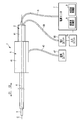
- FIG. 1 is a diagram showing an ultrasonic treatment apparatus 1 of the present embodiment.
- the ultrasonic treatment apparatus 1 of this embodiment is an ultrasonic suction apparatus that selectively crushes and excises living tissue by cavitation generated by ultrasonic vibration and sucks the excised living tissue.
- treatment using a high frequency current is also performed. Therefore, the ultrasonic treatment apparatus 1 is an energy treatment apparatus that performs treatment of a living tissue that is a treatment target using energy such as ultrasonic vibration and high-frequency current.
- the ultrasonic treatment apparatus 1 has a longitudinal axis C.
- one of the directions parallel to the longitudinal axis C (the direction of the arrow C1 in FIG. 1) is the distal direction
- the other of the directions parallel to the longitudinal axis C (the direction of the arrow C2 in FIG. 1) is the proximal direction. is there.
- the distal end direction and the proximal end direction are parallel to the longitudinal axis C.
- the ultrasonic treatment device 1 includes a transducer unit 2, an ultrasonic probe (probe unit) 3, a sheath (sheath unit) 4, and a holding unit 5.
- the vibrator unit 2 includes a vibrator case 11. One end of the cable 6 is connected to the base end of the vibrator case 11. The other end of the cable 6 is connected to the power supply unit 7.
- the power supply unit 7 includes an ultrasonic control unit 8 and a high frequency control unit 9.
- An input unit 10 such as a foot switch is connected to the power supply unit 7.
- FIG. 2 is a diagram showing the configuration of the vibrator unit 2.
- a horn member 12 is provided inside the vibrator case 11.
- the horn member 12 is attached to the vibrator case 11.
- An ultrasonic vibrator 13 including piezoelectric elements 15A to 15C that convert current into ultrasonic vibration is attached to the horn member 12.
- One end of electric signal lines 16A and 16B is connected to the ultrasonic transducer 13.
- the electric signal lines 16 ⁇ / b> A and 16 ⁇ / b> B pass through the inside of the cable 6, and the other end is connected to the ultrasonic control unit 8 of the power supply unit 7.
- the horn member 12 is provided with a cross-sectional area changing portion (horn portion) 18 that expands the amplitude of the ultrasonic vibration.
- the cross-sectional area changing portion 18 is located on the distal direction side with respect to the ultrasonic transducer 13.
- the horn member 12 is formed with a cavity 21 around the longitudinal axis C.
- the cavity 21 extends along the longitudinal axis C from the proximal end to the distal end of the horn member 12.
- a female screw portion 22 is formed at the tip of the inner peripheral surface of the horn member 12.
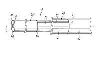
- the ultrasonic probe 3 includes a proximal probe member 23 and a distal probe member 25.
- the proximal-side probe member 23 includes a probe main body 27 that extends along the longitudinal axis C.
- the base end side connection portion 28 is continuous with the base end direction side of the probe main body 27.
- the proximal end side connection portion 28 is formed in a cylindrical shape, and the cross-sectional shape perpendicular to the longitudinal axis C of the proximal end side connection portion 28 is a point-symmetrical shape about the longitudinal axis C. Therefore, the position of the center of gravity of the proximal end side connection portion 28 is located on the longitudinal axis C in the cross section perpendicular to the longitudinal axis C.
- a male screw portion 29 is formed on the outer peripheral portion of the base end side connection portion 28.
- the proximal probe member 23 When the male screw portion 29 is screwed with the female screw portion 22 of the horn member 12, the proximal probe member 23 is connected to the distal direction side of the horn member 12. In a state where the proximal end side probe member 23 is connected to the horn member 12, the proximal end side connection portion 28 is located inside the horn member 12 (hollow portion 21).
- a groove-shaped portion 32 is defined along the longitudinal axis C by a groove defining portion 31 in the probe main body portion 27.
- the groove-like portion 32 extends from the proximal end to the distal end of the probe main body portion 27. That is, the groove-like portion 32 is provided over the entire length of the probe main body portion 27 in the axis parallel direction that is a direction parallel to the longitudinal axis C.
- the groove portion 32 is recessed in a first vertical direction (in the direction of the arrow X1 in FIG. 5) perpendicular to the longitudinal axis C.
- the groove-like portion 32 opens toward the second vertical direction (the direction of the arrow X2 in FIG. 5), which is the direction opposite to the first vertical direction.
- the distal end side connecting portion 33 is continuous with the distal end side of the probe main body 27.
- the distal end side connection portion 33 is formed in a cylindrical shape, and a cross-sectional shape perpendicular to the longitudinal axis C of the distal end side connection portion 33 is a point-symmetric shape with respect to the longitudinal axis C. Therefore, the gravity center position of the distal end side connecting portion 33 is located on the longitudinal axis C in the cross section perpendicular to the longitudinal axis C.
- a male screw portion 35 is formed on the outer peripheral portion of the distal end side connecting portion 33.
- the distal-side probe member 25 is formed in a cylindrical shape, and a cross-sectional shape perpendicular to the longitudinal axis C of the distal-side probe member 25 is a point-symmetric shape with respect to the longitudinal axis C.
- the distal end surface 36 of the distal end side probe member 25 becomes the distal end of the ultrasonic probe 3.
- a hollow portion 37 extends along the longitudinal axis C in the distal probe member 25.
- the hollow portion 37 is open toward the distal end at the distal end surface 36 of the distal end side probe member 25.
- a female screw portion 38 is provided at the proximal end portion of the distal end side probe member 25.
- the distal end side probe member 25 When the male thread portion 35 of the distal end side connection portion 33 is screwed into the female thread portion 38, the distal end side probe member 25 is connected to the distal direction side of the proximal end side probe member 23. In a state where the distal end side probe member 25 is connected to the proximal end side probe member 23, the distal end side connection portion 33 is located inside the distal end side probe member 25 (hollow portion 37).
- the proximal probe member 23 is connected to the horn member 12 and the distal probe member 25 is connected to the proximal probe member 23, whereby the ultrasonic probe 3 is attached to the horn member 12.
- the ultrasonic vibration generated in the ultrasonic transducer 13 is transmitted through the horn member 12, the probe main body 27 (proximal probe member 23), and the distal probe member 25 to the distal end surface of the distal probe member 25.
- ultrasonic vibration is transmitted along the longitudinal axis C from the proximal direction to the distal direction.
- the ultrasonic vibration is longitudinal vibration in which the transmission direction and the vibration direction are parallel to the longitudinal axis C.
- a connection antinode position A1 which is one of antinode positions of ultrasonic vibrations.
- the probe main body 27 is continuous to the distal direction side of the horn member 12.
- connection antinode position A5 which is one of the antinode positions
- the distal end side probe member 25 is continuous with the distal end direction side of the probe main body 27. Therefore, the proximal end of the probe main body 27 is located at the connection antinode position A1, and the tip of the probe main body 27 is located at the connection antinode position A5.
- the groove-like portion 32 extends over the entire length of the probe main body portion 27 in the axis parallel direction. For this reason, in the probe main body portion 27 between the connection antinode position A1 and the connection antinode position A5, the cross-sectional shape perpendicular to the longitudinal axis C is asymmetric with respect to the longitudinal axis C.
- the ultrasonic vibration transmission direction and the cross-sectional shape perpendicular to the vibration direction change. That is, the cross-sectional shape perpendicular to the longitudinal axis C changes from a point-symmetrical shape about the longitudinal axis C to an asymmetrical shape about the longitudinal axis C at the connection antinode position A1.
- the ultrasonic vibration transmission direction and the cross-sectional shape perpendicular to the vibration direction change. That is, the cross-sectional shape perpendicular to the longitudinal axis C changes from an asymmetrical shape about the longitudinal axis C to a symmetrical shape about the longitudinal axis C at the connection antinode position A5.
- the distal end surface 36 (ultrasonic probe) of the distal end side probe member 25 is located at the most distal antinode position A6, which is the antinode position of ultrasonic vibration on the most distal direction side.
- the holding unit 5 includes a holding case 41. Further, the ultrasonic probe 3 is inserted into the sheath 4.
- FIG. 6 is a diagram showing the configuration of the sheath 4 and the ultrasonic probe 3. As shown in FIG. 6, a cavity 42 is formed between the outer peripheral portion (outer surface) of the ultrasonic probe 3 and the inner peripheral portion of the sheath 4.
- a liquid feeding tube 43 extends along the longitudinal axis C in the cavity portion 42. Inside the holding case 41, the distal end portion of the transducer case 11 is attached to the proximal end portion of the sheath 4 via the relay member 45. The liquid feeding tube 43 extends from the cavity 42 to the outside of the sheath 4 at the proximal end portion of the sheath 4.
- the liquid feeding tube 43 extends to the outside of the holding unit 5 and is connected to the liquid feeding unit 47.
- the liquid feeding unit 47 is connected to the input unit 10.
- a liquid such as physiological saline passes through the liquid feeding tube 43.
- liquid feeding to the living tissue or the like is performed from the tip of the liquid feeding tube 43 positioned between the tip of the sheath 4 and the ultrasonic probe 3.
- Cavitation is generated by transmitting ultrasonic vibration to the distal end surface 36 of the distal end side probe member 25 in a state where physiological saline or the like is being delivered in the vicinity of the distal end surface 36.
- Cavitation selectively crushes and emulsifies biological tissue with low elasticity such as hepatocytes. At this time, a highly elastic living tissue such as a blood vessel is not crushed by cavitation. In addition, the bleeding site is confirmed, the body cavity is washed, and the like by liquid feeding to the living tissue.
- the ultrasonic probe 3 includes a tube member 51 that extends along the longitudinal axis C inside the groove-like portion 32.
- the distal end of the tube member 51 is fixed to the inner peripheral portion of the distal end side probe member 25 by adhesion or the like.
- the inside of the tube member 51 communicates with a hollow portion 37 provided inside the distal end side probe member 25.
- the base end of the tube member 51 is fixed to the inner peripheral portion of the horn member 12 by adhesion or the like.
- the inside of the tube member 51 communicates with a cavity portion 21 provided inside the horn member 12.
- one end of a suction tube 53 is connected to the horn member 12.
- the inside of the suction tube 53 communicates with the cavity 21.
- the suction tube 53 extends to the outside of the transducer case 11, and the other end is connected to the suction unit 55.
- the suction unit 55 is connected to the input unit 10.
- the aspiration unit 55 is driven by input from the input unit 10 or the like.
- the suction unit 55 By driving the suction unit 55, the excised living tissue is sucked into the cavity portion 37. Then, the living tissue is sucked up to the suction unit 55 through the inside of the tube member 51, the hollow portion 21, and the inside of the suction tube 53 in order.
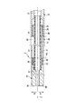
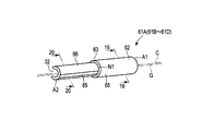
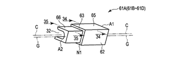
- FIG. 7 is a diagram showing the configuration of the probe main body 27.
- the probe main body 27 includes one or more (four in this embodiment) transmission units 61A to 61D.
- the ultrasonic vibration has three antinode positions A2 to A4 between the connection antinode position A1 where the proximal end of the probe main body 27 is located and the connection antinode position A5 where the tip of the probe main body 27 is located.
- the antinode position A3 is located on the distal direction side of the antinode position A2, and the antinode position A4 is located on the distal direction side of the antinode position A3.
- the transmission unit 61A extends along the longitudinal axis C from the connection antinode position A1 to the antinode position A2, and the transmission unit 61B extends along the longitudinal axis C from the antinode position A2 to the antinode position A3.
- the transmission unit 61C extends along the longitudinal axis C from the antinode position A3 to the antinode position A4, and the transmission unit 61D extends along the longitudinal axis C from the antinode position A4 to the connection antinode position A5.
- the front end of the transmission unit 61A and the base end of the transmission unit 61B are continuous at the antinode position A2, and the front end of the transmission unit 61B and the base end of the transmission unit 61C are continuous at the antinode position A3.
- antinode position A4 between the front-end
- the node position N1 is positioned between the connection antinode position A1 and the antinode position A2, and the node position N2 is positioned between the antinode position A2 and the antinode position A3.
- the node position N3 is located between the antinode position A3 and the antinode position A4, and the node position N4 is located between the antinode position A4 and the connection antinode position A5.
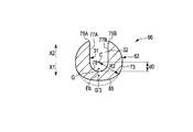
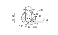
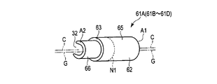
- FIG. 8 is a diagram showing a configuration of a certain transmission unit 61A.
- 9 is a cross-sectional view taken along line IX-IX in FIG. 8
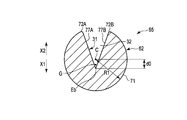
- FIG. 10 is a cross-sectional view taken along line XX in FIG.
- the transmission unit 61A will be described, but the other transmission units 61B to 61D are the same as the transmission unit 61A.
- the transmission unit 61 ⁇ / b> A includes a unit outer surface 62 that is a part of the outer peripheral portion (outer surface) of the probe main body 27.
- the unit outer surface 62 is extended along the longitudinal axis C in a state exposed to the outside.
- the groove-shaped portion 32 is formed over the entire length in the axis parallel direction. Therefore, also in the transmission unit 61 ⁇ / b> A, the groove-shaped portion 32 is defined by the groove defining portion 31 over the entire length in the axis parallel direction. As described above, the groove portion 32 is recessed in the first vertical direction (the direction of the arrow X1 in FIGS.
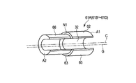
- the transmission unit 61A includes a cross-sectional area changing unit 63 in which the cross-sectional area of the ultrasonic probe 3 perpendicular to the longitudinal axis C changes.
- the cross-sectional area changing portion 63 is formed in a step shape and is located at the node position N1 of ultrasonic vibration in the axis parallel direction. That is, the node position N1 is a cross-sectional area changing node position at which the cross-sectional area of the ultrasonic probe 3 perpendicular to the longitudinal axis C changes.
- the transmission unit 61A includes a first unit component 65 extending along the longitudinal axis C between the connection antinode position (first antinode position) A1 and the cross sectional area changing portion 63, and a cross sectional area change. And a second unit component 66 extending along the longitudinal axis C between the portion 63 and the antinode position (second antinode position) A2. That is, the first unit component 65 extends between the connection antinode position (first antinode position) A1 and the node position (cross-sectional area changing node position) N1, and the second unit component 66 is the node position.
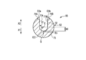
- FIG. 9 shows a cross section perpendicular to the longitudinal axis C in the first unit component 65
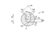
- FIG. 10 shows a cross section perpendicular to the longitudinal axis C in the second unit component 66.
- the first unit component 65 has a first cross-sectional shape having a first cross-sectional area S1 in a cross section perpendicular to the longitudinal axis C.
- the second unit component 66 has a second cross-sectional shape that has a second cross-sectional area S ⁇ b> 2 smaller than the first cross-sectional area S ⁇ b> 1 in a cross-section perpendicular to the longitudinal axis C. . Therefore, in the cross-sectional area changing portion 63, the cross-sectional area of the ultrasonic probe 3 (probe main body portion 27) perpendicular to the longitudinal axis C decreases.
- the amplitude of the ultrasonic vibration is increased in the cross-sectional area changing unit 63. Also at the node positions N2 to N4, the amplitude of the ultrasonic vibration is expanded in the same manner as the node position N1. Thereby, the ultrasonic vibration whose amplitude is enlarged is transmitted to the distal end surface 36 of the ultrasonic probe 3.
- the first unit component 65 of the transmission unit 61B is continuous with the distal direction side of the second unit component 66 of the transmission unit 61A. ing. That is, at the antinode position A2, the cross-sectional area of the ultrasonic probe 3 (probe main body 27) perpendicular to the longitudinal axis C increases from the second cross-sectional area S2 to the first cross-sectional area S1.
- the amplitude of the ultrasonic vibration does not change at the antinode position A2 between the transmission unit 61A and the transmission unit 61B.
- the amplitude of the ultrasonic vibration does not change as in the antinode position A2.
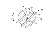
- the first unit component 65 includes a first arcuate surface 71 that is located at a distance of the first radial dimension R1 from the longitudinal axis C in the first cross-sectional shape.
- the first arcuate surface 71 is a part of the unit outer surface 62 and extends in an arcuate shape with the longitudinal axis C as the center.
- the first unit component 65 includes first chamfered portions 72A and 72B that are continuous between the first arcuate surface 71 and the groove defining portion 31 in the first cross-sectional shape.
- the first chamfered portions 72 ⁇ / b> A and 72 ⁇ / b> B are part of the unit outer surface 62.
- the first arcuate surface 71 is continuous in the direction around the longitudinal axis between the first chamfered portion 72A and the first chamfered portion 72B. Therefore, in the first cross-sectional shape, on the first vertical direction side from the longitudinal axis C, the first arcuate surface 71 is continuous as the outer surface (outer peripheral portion).
- the first chamfered portions 72A and 72B are not provided, and the first virtual shape (the shape indicated by the dotted line in FIG. 9)
- the cross-sectional area perpendicular to the longitudinal axis C is reduced by 1 reduction area S′1. That is, the first cross-sectional area S1 of the first cross-sectional shape is a cross-sectional area that is reduced by the first reduced area S′1 from the cross-sectional area of the first virtual shape.
- the first arcuate surface 71 and the groove defining portion 31 are directly continuous (without relaying the first chamfered portions 72A and 72B). .
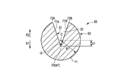
- the second unit component 66 has a second cross-sectional shape that is located away from the longitudinal axis C by a second radial dimension R2 that is smaller than the first radial dimension R1.
- An arcuate surface 73 is provided.
- the second arcuate surface 73 is a part of the unit outer surface 62 and extends in an arcuate shape with the longitudinal axis C as the center.
- the second unit component 66 includes second chamfered portions 75A and 75B that are continuous between the second arcuate surface 73 and the groove defining portion 31 in the second cross-sectional shape.
- the second chamfered portions 75 ⁇ / b> A and 75 ⁇ / b> B are part of the unit outer surface 62.
- the second arcuate surface 73 is continuous in the direction around the longitudinal axis between the second chamfered portion 75A and the second chamfered portion 75B. Therefore, in the second cross-sectional shape, on the first vertical direction side from the longitudinal axis C, the second arcuate surface 73 is continuous as the outer surface (outer peripheral portion).
- the second chamfered portions 75A and 75B are not provided, and the second virtual shape (the shape indicated by the dotted line in FIG. 10)
- the cross-sectional area perpendicular to the longitudinal axis C is reduced by a reduced area S′2 of 2. That is, the second cross-sectional area S2 of the second cross-sectional shape is a cross-sectional area that is reduced from the cross-sectional area of the second virtual shape by the second reduced area S′2.
- the second arcuate surface 73 and the groove defining portion 31 are directly continuous (without relaying the second chamfered portions 75A and 75B). .
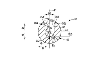
- the groove defining portion 31 extends in a substantially U shape in a cross section perpendicular to the longitudinal axis C. That is, the groove defining portion 31 includes groove side surfaces 77A and 77B (first groove side surface 77A and second groove surface) extending in parallel with the first vertical direction and the second vertical direction in a cross section perpendicular to the longitudinal axis C. A groove side surface 77B) and a groove bottom surface 78 continuous between the groove side surface 77A and the groove side surface 77B in a cross section perpendicular to the longitudinal axis C.
- the groove bottom surface 78 is formed in an arc shape in a cross section perpendicular to the longitudinal axis C.
- the position of the groove bottom surface 78 with the longitudinal axis C as a reference position is aligned over the entire length in the axis parallel direction. Therefore, in the transmission unit 61A (61B to 61D), the position of the groove bottom end Eb with the longitudinal axis C in the cross section perpendicular to the longitudinal axis C as the reference position in the first vertical direction and the second vertical direction is It coincides over the entire length in the axis parallel direction. That is, the position of the groove bottom end Eb with the longitudinal axis C as the reference position changes between the first cross-sectional shape of the first unit component 65 and the second cross-sectional shape of the second unit component 66. do not do.
- the groove bottom end Eb of the groove-shaped portion 32 is located on the first vertical direction side from the longitudinal axis C over the entire length of the transmission unit 61A in the axis parallel direction. Therefore, in this embodiment, the groove bottom end Eb of the groove-shaped portion 32 is separated from the longitudinal axis C by the predetermined bottom end dimension d0 in the first vertical direction over the entire length of the transmission unit 61A in the axis parallel direction. positioned.
- a reference axis P that is parallel to the first vertical direction and the second vertical direction and passes through the longitudinal axis C is defined.
- a direction perpendicular to the longitudinal axis C and perpendicular to the reference axis P (first vertical direction and second vertical direction) is defined as a groove width direction (the direction of arrow B in FIGS. 9 and 10).
- the dimension of the groove-shaped part 32 in the groove width direction is the groove width dimension.
- the first virtual shape has the same predetermined radius as the first cross-sectional shape in the first columnar shape having the same radius as the first radial dimension R1 and point-symmetric about the longitudinal axis.
- This is a shape in which a groove-like portion 32 having a bottom end dimension d0 and a predetermined groove width dimension b0 is formed.
- the first arcuate surface 71 and the groove defining portion 31 are directly continuous.
- the second virtual shape has a predetermined bottom that is the same as the second cross-sectional shape in a second columnar shape having the same radius as the second radial dimension R2 and point-symmetrical about the longitudinal axis.
- the second arcuate surface 73 and the groove defining portion 31 are directly continuous.
- the second columnar shape is a similar shape obtained by reducing the first columnar shape.
- the radial dimension between the longitudinal axis C and the outer surface is the second dimension.
- the second radial dimension R2 of the virtual shape is smaller than the first radial dimension R1 of the first virtual shape.
- the dimensions match.
- the first chamfered portions 72A and 72B are not provided in the first virtual shape, and the second chamfered portions 75A and 75B are not provided in the second virtual shape.
- the second virtual centroid position G′2 which is the centroid position of the second virtual shape, is compared to the first vertical centroid position G′1, which is the centroid position of the first virtual shape. Located on the direction side.
- the first chamfered portions 72A and 72B are provided, and the first chamfered portions 72A and 72B are relayed between the first arcuate surface 71 and the groove defining portion 31. (Indirectly) and continuous.
- the second chamfered portions 75A and 75B are provided, and the second chamfered portions 75A and 75B are relayed between the second arcuate surface 73 and the groove defining portion 31. It is continuous (indirectly).
- the shape of the second chamfered portions 75A and 75B with respect to the first chamfered portions 72A and 72B changes between the first cross-sectional shape and the second cross-sectional shape.
- the second chamfered portions 75A and 75B have the same center-of-gravity position G in the first unit component 65 and the second unit component 66 when the longitudinal axis C in the cross section perpendicular to the longitudinal axis C is the reference position.
- the shape changes to the first chamfered portions 72A and 72B.
- the first chamfered portions 72A and 72B are first curved surface portions formed in an arc shape in the first cross-sectional shape.
- the arc centers O1a, O1b of the first curved surface portions (72A, 72B) are located on the inner circumferential direction side from the unit outer surface 62 (first arc-shaped surface 71).
- the 1st curved surface part (72A, 72B) has the 1st curvature radius r1.
- the second chamfered portions 75A and 75B are second curved surface portions formed in an arc shape in the second cross-sectional shape.
- the arc centers O2a, O2b of the second curved surface portions (75A, 75B) are located on the inner circumferential direction side from the unit outer surface 62 (second arcuate surface 73).
- the 2nd curved surface part (75A, 75B) has the 2nd curvature radius r2 smaller than the 1st curvature radius r1.
- the ratio of the first reduced area S′1 to the first cross-sectional area S1 is defined as the first area ratio.
- the ratio of the second reduced area S′2 to the second cross-sectional area S2 is set as the second area ratio.
- the second curvature radius r2 of the second chamfered portions 75A and 75B is smaller than the first radius of curvature r1 of the first chamfered portions 72A and 72B.
- the second area ratio is smaller than the first area ratio. That is, in the region on the second vertical direction side from the longitudinal axis C, the second virtual area is smaller than the area ratio (first area ratio) that decreases due to the shape change from the first virtual shape to the first cross-sectional shape.
- the center-of-gravity position G when the longitudinal axis C in the section perpendicular to the longitudinal axis C is the reference position is the first unit component between the first sectional shape and the second sectional shape.
- the shape of the second chamfered portions 75A and 75B with respect to the first chamfered portions 72A and 72B is changed to a state in which the second chamfered portion 65A and the second unit constituting portion 66 coincide. That is, between the first cross-sectional shape and the second cross-sectional shape, the center-of-gravity position G when the longitudinal axis C in the cross-section perpendicular to the longitudinal axis C is the reference position is the first unit component 65 and the second cross-sectional shape.
- the shape of the unit outer surface 62 in the cross section perpendicular to the longitudinal axis C changes to a state in which the two unit constituent parts 66 coincide with each other. Since the center of gravity G when the longitudinal axis C in the cross section perpendicular to the longitudinal axis C is the reference position is the same in the first unit component 65 and the second unit component 66, the transmission unit 61A has the longitudinal axis The center-of-gravity position G when the longitudinal axis C in the cross section perpendicular to C is taken as the reference position coincides over the entire length in the axis parallel direction.
- the center-of-gravity position G with the longitudinal axis C in the cross section perpendicular to the longitudinal axis C as the reference position extends over the entire length in the axis parallel direction.
- the center-of-gravity position G when the longitudinal axis C in the cross section perpendicular to the longitudinal axis C is the reference position does not change between the transmission unit 61A and the transmission unit 61B.
- the longitudinal length in the cross section perpendicular to the longitudinal axis C The center-of-gravity position G with the axis C as the reference position does not change. Therefore, the gravity center position G when the longitudinal axis C in the cross section perpendicular to the longitudinal axis C is set as the reference position coincides with the entire length of the probe main body 27 in the axis parallel direction.
- the gravity center position G is located on the reference axis P in the cross section perpendicular to the longitudinal axis C. That is, in the probe main body 27, the gravity center position G is not shifted in the groove width direction with respect to the longitudinal axis C. Further, in the probe main body 27, the gravity center position G is shifted from the longitudinal axis C to the first vertical direction side.
- FIG. 11 is a cross-sectional view taken along line 11-11 in FIG.
- a cylindrical seal member 81 is provided in the cavity 42 between the probe main body 27 and the sheath 4 of the ultrasonic probe 3.
- the seal member 81 is located at any one of the ultrasonic vibration node positions N1 to N4, and in this embodiment, is located at the node position N2.
- an elastic member 82 such as rubber is provided at the node position N2. The elastic member 82 can be engaged with the groove-shaped portion 32 of the probe main body portion 27.
- a cylindrical shape is formed by the probe main body 27 and the elastic member 82 in a cross section perpendicular to the longitudinal axis C.
- the inner peripheral part of the cylindrical seal member 81 is in close contact with the outer peripheral part (outer surface) of the probe main body part 27 and the outer peripheral part of the elastic member 82.
- the outer peripheral portion of the seal member 81 is in close contact with the inner peripheral portion of the sheath 4. Therefore, at the node position N2, the space between the probe main body 27 and the sheath 4 is kept airtight and liquid tight.
- the probe can be obtained even at the node positions (N 1 to N 4) where the cross-sectional shape perpendicular to the longitudinal axis C is located on the probe main body 27 that is asymmetric with respect to the longitudinal axis C.
- the space between the main body 27 and the sheath 4 is kept airtight and liquid tight.
- ultrasonic suction of a living tissue is performed using the ultrasonic treatment apparatus 1
- an ultrasonic current is supplied from the ultrasonic control unit 8 to the ultrasonic transducer 13 via the electric signal lines 16 ⁇ / b> A and 16 ⁇ / b> B.
- Ultrasonic vibration is generated in the vibrator 13.
- the generated ultrasonic vibration is transmitted to the ultrasonic probe 3 through the horn member 12.
- ultrasonic vibration is transmitted from the proximal direction to the distal direction.
- the cross-sectional shape perpendicular to the longitudinal axis C changes from a point-symmetrical shape about the longitudinal axis C to the longitudinal axis C.
- the shape changes to an asymmetrical shape around the center.
- the ultrasonic vibration transmission direction and the cross-sectional shape perpendicular to the vibration direction greatly change at the connection antinode position A1.
- the ultrasonic vibration stress is zero at the ultrasonic vibration antinode position including the connection antinode position A1. Therefore, no stress acts on the ultrasonic vibration at the connection antinode position A1 where the ultrasonic vibration transmission direction and the cross-sectional shape perpendicular to the vibration direction change greatly. Therefore, the vibration mode does not change.
- the ultrasonic vibration transmission direction and the cross-sectional shape perpendicular to the vibration direction are large at the connection antinode position A5 located at the distal end of the probe main body 27 (the proximal end of the distal probe member 25). Change. As described above, the stress due to the ultrasonic vibration is zero at the connection antinode position A5. Accordingly, no stress acts on the ultrasonic vibration at the connection antinode position A5 where the ultrasonic vibration transmission direction and the cross-sectional shape perpendicular to the vibration direction change greatly. Therefore, the vibration mode does not change.
- the position at which the cross-sectional shape perpendicular to the longitudinal axis C changes from a point-symmetrical shape about the longitudinal axis C to an asymmetrical shape about the longitudinal axis C is the ultrasonic probe 3 and the horn member 12. Even when provided, the ultrasonic vibration is not affected by the stress.
- each of the transmission units 61A to 61D of the probe main body 27 is provided with a cross-sectional area changing portion 63.
- the cross-sectional area changing portion 63 is provided at the node positions (N1 to N4) located at the antinode positions of the ultrasonic vibration.
- the cross-sectional area perpendicular to the longitudinal axis C decreases. For this reason, in the cross-sectional area change part 63, the amplitude of ultrasonic vibration is expanded.
- the amplitude of the ultrasonic vibration is increased, whereby the amplitude is increased on the distal end surface 36 of the ultrasonic probe 3. Treatment is performed using ultrasonic vibration.
- each of the transmission units 61A to 61D there is a longitudinal difference between the first cross-sectional shape of the first unit component 65 and the second cross-sectional shape of the second unit component 66.
- the gravity center position G with the axis C as the reference position does not change. That is, in each of the transmission units 61A to 61D, the center-of-gravity position G when the longitudinal axis C in the cross section perpendicular to the longitudinal axis C is used as the reference position is the same over the entire length in the axis parallel direction.
- the longitudinal axis The center-of-gravity position G when the longitudinal axis C in the cross section perpendicular to C is taken as the reference position does not change at the cross-sectional area changing portion 63. That is, in the probe main body 27, the center-of-gravity position G when the longitudinal axis C in the cross section perpendicular to the longitudinal axis C is set as the reference position at positions other than the antinode position of the ultrasonic vibration does not change.
- the cross-sectional area changing portion 63 is provided in each of the transmission units 61A to 61D whose cross-sectional shape perpendicular to the longitudinal axis C is asymmetric with respect to the longitudinal axis C, the ultrasonic vibration is affected by the stress. Not receive.
- the ultrasonic vibration is not affected by the stress. Therefore, the transmission property of the ultrasonic vibration is ensured, and the ultrasonic vibration is appropriately transmitted to the distal end surface 36 of the ultrasonic probe 3 (front end side probe member 25). Further, since the ultrasonic vibration is hardly affected by the stress, the strength of the ultrasonic probe 3 is ensured.
- Cavitation is generated by transmitting ultrasonic vibration to the distal end surface 36 of the distal end side probe member 25 (ultrasonic probe 3).
- ultrasonic vibration By cavitation, biological tissue with low elasticity such as hepatocytes is selectively crushed and excised.
- ultrasonic vibration By appropriately transmitting ultrasonic vibration to the distal end surface 36 of the ultrasonic probe 3, cavitation is more efficiently generated, and treatment such as ultrasonic suction is appropriately performed using the cavitation.
- each of the transmission units 61A to 61D the position of the groove bottom end Eb with the longitudinal axis C in the cross section perpendicular to the longitudinal axis C as the reference position in the first vertical direction and the second vertical direction is axially parallel. Match over the entire length in the direction. For this reason, in each of the transmission units 61A to 61D, the groove portion 32 is easily formed by milling. In addition, the first chamfered portions 72A and 72B and the second chamfered portions 75A and 75B are formed in a short time and at a low cost. Therefore, the transmission units 61A to 61D are formed efficiently and at low cost. Therefore, the probe main body 27 and the ultrasonic probe 3 can be manufactured efficiently and at low cost.
- proximal end side connecting portion 28 for connecting the probe main body portion 27 to the horn member 12 and the distal end side connecting portion 33 for connecting the probe main body portion 27 to the distal end side probe member 25 are formed in a cylindrical shape. That is, in the proximal end side connection portion 28 and the distal end side connection portion 33, the cross-sectional shape perpendicular to the longitudinal axis C is point symmetric about the longitudinal axis C. For this reason, even when the probe main body portion 27 whose cross-sectional shape perpendicular to the longitudinal axis C is asymmetric with respect to the longitudinal axis C is provided, the strength of the proximal end side connection portion and the distal end side connection portion 33 is ensured.
- the elastic member 82 causes the probe main body portion 27 to cross the probe main body portion 27 at the node position (N2) where the cross-sectional shape perpendicular to the longitudinal axis C is located on the probe main body portion 27 that is asymmetric about the longitudinal axis C Airtightness and liquid tightness are maintained between the sheath 4. For this reason, the pressure in the abdominal cavity is maintained in the treatment with the abdominal cavity. Moreover, in the treatment in the abdominal cavity, the outflow of fluid such as body fluid from the abdominal cavity toward the proximal end is effectively prevented.
- the shapes of the first chamfered portions 72A and 72B and the second chamfered portions 75A and 75B are not limited to the shapes of the first embodiment.
- the second chamfered portions 75A and 75B may be formed in an inclined plane shape.
- the second chamfered portions 75A and 75B are inclined with respect to the first vertical direction (the direction of the arrow X1 in FIG. 12) and the second vertical direction (the direction of the arrow X2 in FIG. 12). It is extended by.
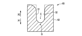
- the second chamfered portions 75A and 75B may be formed in a concave curved surface in the second cross-sectional shape of the second unit component 66.
- the second chamfered portions 75A and 75B are formed in an arc shape in which arc centers O3a and O3b are located on the outer peripheral direction side from the unit outer surface 62 (second arcuate surface 73).
- the arc center O3a of the second chamfered portion 75A and the arc center O3b of the second chamfered portion 75B have different positions.
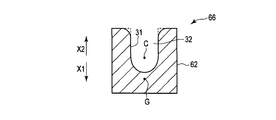
- the second chamfered portions 75A and 75B have the same arc center O4. May be. Also in this modified example, the arc center O4 is located on the outer circumferential direction side from the unit outer surface 62 (second arcuate surface 73), as in the second modified example.
- the second chamfered portions 75A and 75B are provided in the first vertical direction and the second It may be formed in a planar shape perpendicular to the vertical direction.
- the second chamfered portions 75A and 75B are extended in parallel to the groove width direction.
- the first chamfered portions 72A and 72B also have a shape such as an inclined flat surface and a concave curved surface in the first cross-sectional shape of the first unit component 65, similarly to the second chamfered portions 75A and 75B. May be formed.
- the first cross-sectional area S1 of the first cross-sectional shape of the first unit component 65 is provided. Accordingly, the second cross-sectional area S2 of the second cross-sectional shape of the second unit component 66 is small.
- the longitudinal axis C in the second sectional shape is determined from the first radial dimension R1 from the longitudinal axis C in the first sectional shape to the first arcuate surface 71. To the second arcuate surface 73 is small in the second radial dimension R2.
- each of the transmission units 61A to 61D in the cross section perpendicular to the longitudinal axis C, the groove having the longitudinal axis C in the first vertical direction and the second vertical direction as a reference position.
- the position of the bottom end Eb coincides over the entire length in the axis parallel direction.
- the groove width dimension between the groove side surface 77A and the groove side surface 77B is the same over the entire length in the axis parallel direction.
- the second virtual shape (see FIG. 9) is compared to the first virtual center-of-gravity position G′1 of the first virtual shape (the shape indicated by the dotted line in FIG. 9).
- the second virtual center-of-gravity position G′2 of the shape shown by the dotted line in FIG. 12 to FIG. 15 is located on the first vertical direction side. Therefore, in the first to fourth modified examples, as in the first embodiment, the first area ratio of the first reduced area S′1 to the first sectional area S1 is The second area ratio of the second reduced area S′2 to the sectional area S2 of 2 is reduced.
- the second virtual center of gravity position G′2 of the second virtual shape is located on the first vertical direction side from the first virtual center of gravity position G′1 of the first virtual shape, but the first cross section Between the shape and the second cross-sectional shape, the center-of-gravity position G when the longitudinal axis C is taken as the reference position coincides.
- the center-of-gravity position G when the longitudinal axis C in the cross section perpendicular to the longitudinal axis C is the reference position is The shape of the second chamfered portions 75A and 75B with respect to the first chamfered portions 72A and 72B is changed to a state in which the first unit constituting portion 65 and the second unit constituting portion 66 coincide with each other.
- the groove defining portion 31 extends in a substantially U shape in a cross section perpendicular to the longitudinal axis C, but the present invention is not limited to this.
- the groove defining portion 31 may be extended in a substantially V shape in a cross section perpendicular to the longitudinal axis C.
- the groove bottom surface 78 is not provided, and groove side surfaces 77A and 77B are provided.
- the groove side surfaces 77A and 77B are inclined with respect to the first vertical direction (the direction of the arrow X1 in FIGS. 16 and 17) and the second vertical direction (the direction of the arrow X2 in FIGS. 16 and 17). It is extended.
- the second unit component is obtained from the first cross-sectional area S1 of the first cross-sectional shape of the first unit component 65, as in the first embodiment.
- the second sectional area S2 of the second sectional shape 66 is small.
- the longitudinal axis C in the second sectional shape is determined from the first radial dimension R1 from the longitudinal axis C in the first sectional shape to the first arcuate surface 71.
- To the second arcuate surface 73 is small in the second radial dimension R2.
- each of the transmission units 61A to 61D in the cross section perpendicular to the longitudinal axis C, the groove having the longitudinal axis C in the first vertical direction and the second vertical direction as a reference position.
- the position of the bottom end Eb coincides over the entire length in the axis parallel direction.
- the second virtual shape (the shape indicated by the dotted line in FIG. 17) is compared with the first virtual center of gravity position G′1 of the first virtual shape (the shape indicated by the dotted line in FIG. 16).
- the second virtual center-of-gravity position G′2 is located on the first vertical direction side. Therefore, in the present modification, as in the first embodiment, the second area with respect to the second cross-sectional area S2 is compared with the first area ratio of the first reduced area S′1 with respect to the first cross-sectional area S1. The second area ratio of the decrease area S′2 is reduced.
- the second virtual center of gravity position G′2 of the second virtual shape is located on the first vertical direction side from the first virtual center of gravity position G′1 of the first virtual shape, but the first cross section Between the shape and the second cross-sectional shape, the center-of-gravity position G when the longitudinal axis C is taken as the reference position coincides.
- the center-of-gravity position G when the longitudinal axis C in the cross section perpendicular to the longitudinal axis C is the reference position is The shape of the second chamfered portions 75A and 75B with respect to the first chamfered portions 72A and 72B is changed to a state in which the first unit constituting portion 65 and the second unit constituting portion 66 coincide with each other.
- the unit outer surface 62 of each of the transmission units 61A to 61D has the first cross-sectional shape from the longitudinal axis C to the first A first arcuate surface 71 that is spaced apart by a radial dimension R1 and a second cross-sectional shape that is spaced apart from the longitudinal axis C by a second radial dimension R2 that is smaller than the first radial dimension R1. 2 arcuate surfaces 73 may be provided.
- the position of the groove bottom end Eb with the longitudinal axis C as the reference position in the first vertical direction and the second vertical direction is axially parallel.
- the groove-shaped part 32 should just be prescribed
- the position of the center of gravity when the longitudinal axis C in the cross section perpendicular to the longitudinal axis C is the reference position is the first unit component 65 and the second sectional shape.
- the shape of the second chamfered portions 75A and 75B with respect to the first chamfered portions 72A and 72B may be changed to a state in which the unit constituent portions 66 coincide with each other.
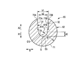
- FIG. 18 is a diagram showing a configuration of a certain transmission unit 61A.
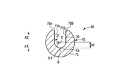
- 19 is a cross-sectional view taken along line 19-19 in FIG. 18, and
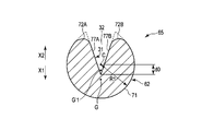
- FIG. 20 is a cross-sectional view taken along line 20-20 in FIG.
- 19 shows a cross section perpendicular to the longitudinal axis C in the first unit component 65
- FIG. 20 shows a cross section perpendicular to the longitudinal axis C in the second unit component 66.
- the second cross-sectional shape of the second unit component 66 is also larger than the first cross-sectional area S1 of the first cross-sectional shape of the first unit component 65.
- the second cross-sectional area S2 becomes small. Therefore, in the cross-sectional area changing portion 63, the cross-sectional area of the ultrasonic probe 3 (probe main body portion 27) perpendicular to the longitudinal axis C decreases. Since the cross-sectional area of the ultrasonic probe 3 perpendicular to the longitudinal axis C decreases at the node position N1 other than the antinode position of the ultrasonic vibration, the amplitude of the ultrasonic vibration is increased in the cross-sectional area changing unit 63. Thereby, also in this embodiment, the ultrasonic vibration whose amplitude is expanded is transmitted to the distal end surface 36 of the ultrasonic probe 3.
- the first unit component 65 includes a first arcuate surface 71 positioned away from the longitudinal axis C by a first radial dimension R1 in the first cross-sectional shape.
- the first unit component 65 includes first chamfered portions 72A and 72B that are continuous between the first arcuate surface 71 and the groove defining portion 31 in the first cross-sectional shape.
- the first arcuate surface 71 is continuous in the direction around the longitudinal axis between the first chamfered portion 72A and the first chamfered portion 72B. Therefore, in the first cross-sectional shape, on the first vertical direction side from the longitudinal axis C, the first arcuate surface 71 is continuous as the outer surface (outer peripheral portion).
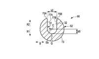
- the second unit component 66 has a second cross-sectional shape that is located away from the longitudinal axis C by a second radial dimension R2 that is smaller than the first radial dimension R1.
- An arcuate surface 73 is provided.
- the second unit component 66 includes second chamfered portions 75A and 75B that are continuous between the second arcuate surface 73 and the groove defining portion 31 in the second cross-sectional shape.
- the second unit component 66 includes a dimension reduction surface 85 whose radial dimension from the longitudinal axis C is smaller than the second radial dimension R2.
- the dimension reduction surface 85 is a part of the unit outer surface 62 and is provided on the first vertical direction side from the gravity center position G in the second cross-sectional shape.
- the dimension reduction surface 85 is formed in a planar shape in the second cross-sectional shape.
- the second arcuate surface 73 is not continuous in the direction around the longitudinal axis between the second chamfered portion 75A and the second chamfered portion 75B. That is, in the second cross-sectional shape, the second arcuate surface 73 is not continuous as the outer surface (outer peripheral portion) on the first vertical direction side from the longitudinal axis C.
- the virtual area (the shape indicated by the dotted line in FIG. 20) in which the dimension reducing surface 85 is not provided is perpendicular to the longitudinal axis C by the reduced area S′3.
- the cross-sectional area is decreasing. That is, the second cross-sectional area S2 of the second cross-sectional shape is a cross-sectional area that is reduced from the virtual cross-sectional area by the reduced area S′3.
- the second arcuate surface 73 is continuous in the direction around the longitudinal axis between the second chamfered portion 75A and the second chamfered portion 75B.
- the groove defining portion 31 extends in a substantially U shape in a cross section perpendicular to the longitudinal axis C.
- the position of the groove bottom surface 78 with the longitudinal axis C as the reference position in the cross section perpendicular to the longitudinal axis C is the entire length in the axis parallel direction. Match across. Therefore, in the transmission unit 61A (61B to 61D), the position of the groove bottom end Eb with the longitudinal axis C in the cross section perpendicular to the longitudinal axis C as the reference position in the first vertical direction and the second vertical direction is It coincides over the entire length in the axis parallel direction. That is, the position of the groove bottom end Eb with the longitudinal axis C as the reference position changes between the first cross-sectional shape of the first unit component 65 and the second cross-sectional shape of the second unit component 66. do not do.
- the width dimension is consistent over the entire length in the axial parallel direction. That is, in the transmission unit 61A (61B to 61D), a predetermined groove width dimension b0 is provided between the groove side surface 77A and the groove side surface 77B in the groove width direction over the entire length in the axis parallel direction. Therefore, the groove width dimension between the groove side surface 77A and the groove side surface 77B changes between the first cross-sectional shape of the first unit component 65 and the second cross-sectional shape of the second unit component 66. do not do.
- first chamfered portions 72A and 72B of the present embodiment are first curved surface portions formed in an arc shape in the first sectional shape, and in the first sectional shape, the first curved surface portion (72A , 72B) are located closer to the inner circumferential direction than the unit outer surface 62 (first arcuate surface 71).
- the second chamfered portions 75A and 75B are second curved surface portions formed in an arc shape in the second cross-sectional shape, and in the second cross-sectional shape, the second curved surface portions (75A and 75B).
- the arc centers O2a and O2b are located on the inner circumferential direction side of the unit outer surface 62 (second arcuate surface 73).
- the first curved surface portion (72A, 72B) and the second curved surface portion (75A, 75B) have the same radius of curvature r0. Accordingly, in the present embodiment, unlike the first embodiment, the second chamfered portions 75A and 75B with respect to the first chamfered portions 72A and 72B between the first cross-sectional shape and the second cross-sectional shape. The shape does not change.
- the first cross-sectional shape is a first columnar shape having the same radius as the first radial dimension R1 and point-symmetric about the longitudinal axis, and has a predetermined bottom end dimension d0 and a predetermined groove.
- This is a shape in which a groove-like portion 32 having a width dimension b0 is formed.
- first chamfered portions 72A and 72B are formed.
- the virtual shape and the second cross-sectional shape have a predetermined bottom end dimension d0 and a predetermined shape in a second columnar shape having the same radius as the second radial dimension R2 and point-symmetric about the longitudinal axis.
- the groove-shaped portion 32 having the groove width dimension b0 is formed.
- second chamfered portions 75A and 75B having the same radius of curvature r0 as the first chamfered portions 72A and 72B are formed.
- the second columnar shape is a similar shape obtained by reducing the first columnar shape.
- the virtual shape second Is smaller than the first radial dimension R1 of the first cross-sectional shape.
- the position of the groove bottom end Eb of the groove-shaped portion 32 with the longitudinal axis C as the reference position and the groove width dimension between the groove side surface 77A and the groove side surface 77B are equal. I'm doing it.
- the first chamfered portions 72A and 72B having the first cross-sectional shape and the second chamfered portions 75A and 75B having the virtual shape substantially coincide with each other in a cross section perpendicular to the longitudinal axis.
- the first arcuate surface 71 is continuous between the first chamfered portion 72A and the first chamfered portion 72B in the first cross-sectional shape, and the second chamfered portion 75A and the second chamfered in the virtual shape.
- the second arcuate surface 73 is continuous with the portion 75B.
- a dimension reducing surface 85 is provided on the first vertical direction side from the gravity center position G.
- the second arcuate surface 73 is not continuous between the second chamfered portion 75A and the second chamfered portion 75B in the second cross-sectional shape. Then, between the first cross-sectional shape and the second cross-sectional shape, the shape of the dimension reducing surface 85 with respect to the first arcuate surface 71 changes on the first vertical direction side from the gravity center position G.
- the dimension reduction surface 85 is in a state where the center of gravity G when the longitudinal axis C in the cross section perpendicular to the longitudinal axis C is the reference position is the same in the first unit component 65 and the second unit component 66.
- the shape changes with respect to the first arcuate surface 71.
- the second cross-sectional area S2 is reduced from the virtual cross-sectional area by the reduced area S′3. That is, in the region on the first vertical direction side from the gravity center position G, the cross-sectional area decreases due to the shape change from the virtual shape to the second cross-sectional shape. For this reason, the virtual center of gravity G′3 of the virtual shape is located on the first vertical direction side from the center of gravity G of the first cross-sectional shape, but between the first cross-sectional shape and the second cross-sectional shape, The center of gravity position G when the longitudinal axis C is set as the reference position coincides.
- the center-of-gravity position G when the longitudinal axis C in the section perpendicular to the longitudinal axis C is the reference position is the first unit component between the first sectional shape and the second sectional shape.
- the shape of the dimension reducing surface 85 with respect to the first arcuate surface 71 is changed to a state in which the first unit arcuate surface 71 and the second unit constituent portion 66 coincide. That is, between the first cross-sectional shape and the second cross-sectional shape, the center-of-gravity position G when the longitudinal axis C in the cross-section perpendicular to the longitudinal axis C is the reference position is the first unit component 65 and the second cross-sectional shape.
- the shape of the unit outer surface 62 in the cross section perpendicular to the longitudinal axis C changes to a state in which the two unit constituent parts 66 coincide with each other. Since the center of gravity G when the longitudinal axis C in the cross section perpendicular to the longitudinal axis C is the reference position is the same in the first unit component 65 and the second unit component 66, the transmission unit 61A has the longitudinal axis The center-of-gravity position G when the longitudinal axis C in the cross section perpendicular to C is taken as the reference position coincides over the entire length in the axis parallel direction.
- the center-of-gravity position G with the longitudinal axis C in the cross section perpendicular to the longitudinal axis C as the reference position extends over the entire length in the axis parallel direction.
- the center-of-gravity position G when the longitudinal axis C in the cross section perpendicular to the longitudinal axis C is the reference position does not change between the transmission unit 61A and the transmission unit 61B.
- the longitudinal length in the cross section perpendicular to the longitudinal axis C The center-of-gravity position G with the axis C as the reference position does not change. Therefore, the gravity center position G when the longitudinal axis C in the cross section perpendicular to the longitudinal axis C is set as the reference position coincides with the entire length of the probe main body 27 in the axis parallel direction.
- the first cross-sectional shape and the second cross-section of the first unit component 65 are the same as in the first embodiment.
- the center-of-gravity position G with the longitudinal axis C as the reference position does not change between the second cross-sectional shape of the unit component 66. That is, in each of the transmission units 61A to 61D, the center-of-gravity position G when the longitudinal axis C in the cross section perpendicular to the longitudinal axis C is used as the reference position is the same over the entire length in the axis parallel direction.
- the center-of-gravity position G when the longitudinal axis C in the cross section is the reference position does not change at the cross-sectional area changing portion 63. That is, in the probe main body 27, the center-of-gravity position G when the longitudinal axis C in the cross section perpendicular to the longitudinal axis C is set as the reference position at positions other than the antinode position of the ultrasonic vibration does not change.
- the cross-sectional area changing portion 63 is provided in each of the transmission units 61A to 61D whose cross-sectional shape perpendicular to the longitudinal axis C is asymmetric with respect to the longitudinal axis C, the ultrasonic vibration is affected by the stress. Not receive.
- the ultrasonic probe 3 of the present embodiment since the ultrasonic vibration is not affected by the stress as in the first embodiment, the transmission property of the ultrasonic vibration is ensured, and the ultrasonic probe 3 (tip-side probe member) The ultrasonic vibration is appropriately transmitted to the tip surface 36 of 25). Further, similarly to the first embodiment, since the ultrasonic vibration is hardly affected by the stress, the strength of the ultrasonic probe 3 is ensured.
- each of the transmission units 61A to 61D the position of the groove bottom end Eb with the longitudinal axis C in the cross section perpendicular to the longitudinal axis C as the reference position in the first vertical direction and the second vertical direction is axially parallel. Match over the entire length in the direction. For this reason, in each of the transmission units 61A to 61D, the groove portion 32 is easily formed by milling. Further, the formation of the dimension reduction surface 85 is performed in a short time and at a low cost. Therefore, the transmission units 61A to 61D are formed efficiently and at low cost. Therefore, as in the first embodiment, the probe main body 27 and the ultrasonic probe 3 can be manufactured efficiently and at low cost.
- the dimension reducing surface 85 is formed in a planar shape in the second cross-sectional shape, but the present invention is not limited to this.
- the dimension reduction surface 85 may be formed in a curved surface shape in the second cross-sectional shape.
- the dimension reduction surface 85 of the second unit component 66 is provided on the first vertical direction side from the gravity center position G in the second cross-sectional shape.
- the radial dimension from the longitudinal axis C is smaller than the second radial dimension R2.
- the second unit component is obtained from the first cross-sectional area S1 of the first cross-sectional shape of the first unit component 65, as in the second embodiment.
- the second sectional area S2 of the second sectional shape 66 is small.
- the longitudinal axis C in the second sectional shape is determined from the first radial dimension R1 from the longitudinal axis C in the first sectional shape to the first arcuate surface 71.
- To the second arcuate surface 73 is small in the second radial dimension R2.
- each of the transmission units 61A to 61D in the cross section perpendicular to the longitudinal axis C, a groove having the longitudinal axis C in the first vertical direction and the second vertical direction as a reference position.
- the position of the bottom end Eb coincides over the entire length in the axis parallel direction.
- the groove width dimension between the groove side surface 77A and the groove side surface 77B is the same over the entire length in the axis parallel direction.
- the shape of 2nd chamfer part 75A, 75B does not change with respect to 1st chamfer part 72A, 72B between 1st cross-sectional shape and 2nd cross-sectional shape.
- the virtual center of gravity position G′3 of the virtual shape (the shape indicated by the dotted line in FIG. 21) is located on the first vertical direction side as compared to the center of gravity position G of the first cross-sectional shape. Yes. Therefore, in the second cross-sectional shape of this modification example, as in the second embodiment, by providing the dimension reducing surface 85, a cross-sectional area perpendicular to the longitudinal axis C is reduced from the virtual shape by the reduced area S′3. is decreasing.
- the virtual center of gravity position G′3 of the virtual shape is located on the first vertical direction side from the center of gravity position G of the first cross-sectional shape, but between the first cross-sectional shape and the second cross-sectional shape,
- the center of gravity position G when the longitudinal axis C is set as the reference position coincides. That is, as in the second embodiment, between the first cross-sectional shape and the second cross-sectional shape, the center-of-gravity position G when the longitudinal axis C in the cross section perpendicular to the longitudinal axis C is the reference position is the same.
- the shape of the dimension reducing surface 85 with respect to the first arcuate surface 71 changes to a state in which the first unit component 65 and the second unit component 66 match.
- the groove defining portion 31 extends in a substantially U shape in a cross section perpendicular to the longitudinal axis C, but the present invention is not limited to this.
- the groove defining portion 31 may be extended in a substantially V shape in a cross section perpendicular to the longitudinal axis C.
- the groove bottom surface 78 is not provided, and groove side surfaces 77A and 77B are provided.
- the groove side surfaces 77A and 77B are inclined with respect to the first vertical direction (the direction of the arrow X1 in FIGS. 22 and 23) and the second vertical direction (the direction of the arrow X2 in FIGS. 22 and 23). It is extended.
- the second unit constituent part is obtained from the first cross-sectional area S1 of the first cross-sectional shape of the first unit constituent part 65, as in the second embodiment.
- the second sectional area S2 of the second sectional shape 66 is small.
- the longitudinal axis C in the second sectional shape is determined from the first radial dimension R1 from the longitudinal axis C in the first sectional shape to the first arcuate surface 71.
- To the second arcuate surface 73 is small in the second radial dimension R2.
- each of the transmission units 61A to 61D in the cross section perpendicular to the longitudinal axis C, a groove having the longitudinal axis C in the first vertical direction and the second vertical direction as a reference position.
- the position of the bottom end Eb coincides over the entire length in the axis parallel direction.
- the virtual center of gravity position G′3 of the virtual shape (the shape indicated by the dotted line in FIG. 23) is located on the first vertical direction side as compared to the center of gravity position G of the first cross-sectional shape. Yes. Therefore, in the second cross-sectional shape of this modification example, as in the second embodiment, by providing the dimension reducing surface 85, a cross-sectional area perpendicular to the longitudinal axis C is reduced from the virtual shape by the reduced area S′3. is decreasing.
- the virtual center of gravity position G′3 of the virtual shape is located on the first vertical direction side from the center of gravity position G of the first cross-sectional shape, but between the first cross-sectional shape and the second cross-sectional shape,
- the center of gravity position G when the longitudinal axis C is set as the reference position coincides. That is, as in the second embodiment, between the first cross-sectional shape and the second cross-sectional shape, the center-of-gravity position G when the longitudinal axis C in the cross section perpendicular to the longitudinal axis C is the reference position is the same.
- the shape of the dimension reducing surface 85 with respect to the first arcuate surface 71 changes to a state in which the first unit component 65 and the second unit component 66 match.
- the unit outer surfaces 62 of the respective transmission units 61A to 61D are separated from the longitudinal axis C in the first cross-sectional shape.
- a first arcuate surface 71 that is spaced apart by a radial dimension R1 and a second cross-sectional shape that is spaced apart from the longitudinal axis C by a second radial dimension R2 that is smaller than the first radial dimension R1. 2 arcuate surfaces 73 may be provided.
- each of the transmission units 61A to 61D in the cross section perpendicular to the longitudinal axis C, the position of the groove bottom end Eb with the longitudinal axis C as the reference position in the first vertical direction and the second vertical direction is axially parallel.
- the groove-shaped part 32 should just be prescribed
- the position of the center of gravity when the longitudinal axis C in the cross section perpendicular to the longitudinal axis C is the reference position is the first unit component 65 and the second sectional shape.
- the shape of the dimension reducing surface 85 with respect to the first arcuate surface 71 may be changed to a state in which the unit constituent portions 66 coincide with each other.
- the shape of the second chamfered portions 75A and 75B with respect to the first chamfered portions 72A and 72B changes between the first cross-sectional shape and the second cross-sectional shape.
- the shape of the dimension reduction surface 85 with respect to the 1st circular arc-shaped surface 71 changes between 1st cross-sectional shape and 2nd cross-sectional shape.
- the first chamfered portions 72 ⁇ / b> A and 72 ⁇ / b> B and the second chamfered portions 75 ⁇ / b> A and 75 ⁇ / b> B are part of the unit outer surface 62.
- the first arcuate surface 71 and the dimension reducing surface 85 are a part of the unit outer surface 62.
- the outer surface 62 includes a first arcuate surface 71 positioned away from the longitudinal axis C by a first radial dimension R1 in the first cross-sectional shape, and a first diameter from the longitudinal axis C in the second cross-sectional shape.
- a second arcuate surface 73 that is spaced apart by a second radial dimension R2 that is smaller than the directional dimension R1.
- each of the transmission units 61A to 61D in the cross section perpendicular to the longitudinal axis C, the position of the groove bottom end Eb with the longitudinal axis C as the reference position in the first vertical direction and the second vertical direction is axially parallel.
- the groove-like portion 32 is defined so as to coincide with the entire length in the direction.
- the center-of-gravity position G when the longitudinal axis C in the cross-section perpendicular to the longitudinal axis C is the reference position is the first unit component 65 and the second cross-sectional shape.
- the shape of the unit outer surface 62 in the cross section perpendicular to the longitudinal axis C changes to a state in which the two unit constituent parts 66 coincide with each other.
- FIG. 24 is a diagram showing a configuration of a certain transmission unit 61A.
- FIG. 25 is a cross-sectional view perpendicular to the longitudinal axis C in the first unit component 65
- FIG. 26 is a cross-sectional view perpendicular to the longitudinal axis C in the second unit component 66.
- the transmission unit 61A will be described, but the other transmission units 61B to 61D are the same as the transmission unit 61A.
- the second cross-sectional shape of the second unit component 66 is also larger than the first cross-sectional area S1 of the first cross-sectional shape of the first unit component 65.
- the second cross-sectional area S2 becomes small. Therefore, in the cross-sectional area changing portion 63, the cross-sectional area of the ultrasonic probe 3 (probe main body portion 27) perpendicular to the longitudinal axis C decreases. Since the cross-sectional area of the ultrasonic probe 3 perpendicular to the longitudinal axis C decreases at the node position N1 other than the antinode position of the ultrasonic vibration, the amplitude of the ultrasonic vibration is increased in the cross-sectional area changing unit 63. Thereby, also in this embodiment, the ultrasonic vibration whose amplitude is expanded is transmitted to the distal end surface 36 of the ultrasonic probe 3.
- the first unit component 65 includes a first arcuate surface 71 located at a distance of the first radial dimension R1 from the longitudinal axis C in the first cross-sectional shape.
- the first unit component 65 includes first chamfered portions 72A and 72B that are continuous between the first arcuate surface 71 and the groove defining portion 31 in the first cross-sectional shape.
- the first arcuate surface 71 is continuous in the direction around the longitudinal axis between the first chamfered portion 72A and the first chamfered portion 72B. Therefore, in the first cross-sectional shape, on the first vertical direction side from the longitudinal axis C, the first arcuate surface 71 is continuous as the outer surface.
- the second unit component 66 has a second cross-sectional shape that is located away from the longitudinal axis C by a second radial dimension R2 that is smaller than the first radial dimension R1.
- An arcuate surface 73 is provided.
- the second unit component 66 includes second chamfered portions 75A and 75B that are continuous between the second arcuate surface 73 and the groove defining portion 31 in the second cross-sectional shape.
- the second arcuate surface 73 is continuous in the direction around the longitudinal axis between the second chamfered portion 75A and the second chamfered portion 75B. Therefore, in the second cross-sectional shape, on the first vertical direction side from the longitudinal axis C, the second arcuate surface 73 is continuous as the outer surface.
- the second chamfered portions 75A, 75A, 72B, 72B, and 72C are between the first cross-sectional shape and the second cross-sectional shape.
- the shape of 75B does not change.
- the groove defining portion 31 extends in a substantially U shape in a cross section perpendicular to the longitudinal axis C.
- the groove width dimension between the groove side surface (first groove side surface) 77A and the groove side surface (second groove side surface) 77B in the cross section perpendicular to the longitudinal axis C is It is consistent over the entire length in the axis parallel direction. That is, in the transmission unit 61A (61B to 61D), a predetermined groove width dimension b0 is provided between the groove side surface 77A and the groove side surface 77B in the groove width direction over the entire length in the axis parallel direction. Therefore, the groove width dimension between the groove side surface 77A and the groove side surface 77B changes between the first cross-sectional shape of the first unit component 65 and the second cross-sectional shape of the second unit component 66. do not do.
- a groove bottom surface 78 having the longitudinal axis C as a reference position in a cross section perpendicular to the longitudinal axis C. Is different between the first cross-sectional shape and the second cross-sectional shape. Therefore, in the transmission unit 61A (61B to 61D), the position of the groove bottom end Eb with the longitudinal axis C in the cross section perpendicular to the longitudinal axis C as the reference position in the first vertical direction and the second vertical direction is It changes between the first cross-sectional shape and the second cross-sectional shape.
- the groove bottom end Eb is located at the first bottom end position e1.
- the groove bottom end Eb is located at the second bottom end position e2 on the first vertical direction side from the first bottom end position e1.
- the first bottom end position e1 and the second bottom end position e2 are located on the first vertical direction side from the longitudinal axis C.
- the groove bottom end Eb is positioned at the second bottom end position e2, so that the position of the groove bottom end Eb with respect to the longitudinal axis C coincides with the first cross-sectional shape.
- the cross-sectional area perpendicular to the longitudinal axis C is reduced by the reduced area S′4. That is, the second cross-sectional area S2 of the second cross-sectional shape is a cross-sectional area that is reduced from the virtual cross-sectional area by the reduced area S′4.
- the groove bottom end Eb (first bottom end position e1) is located away from the longitudinal axis C by the first bottom end dimension d1 in the first vertical direction.
- the groove bottom end Eb (second bottom end position e2) is a first vertical direction from the longitudinal axis C by a second bottom end dimension d2 that is larger than the first bottom end dimension d1.
- the groove bottom end Eb is located away from the longitudinal axis C by the first bottom end dimension d1 in the first vertical direction.
- the first cross-sectional shape is a first columnar shape whose radius is the same as the first radial direction dimension R1 and point-symmetric about the longitudinal axis, and the first bottom end dimension d1 and a predetermined groove width dimension.
- a groove-like portion 32 having b0 is formed.
- first chamfered portions 72A and 72B are formed.
- the imaginary shape and the second cross-sectional shape are the same as the second radial dimension R2, and the groove-like portion 32 is formed in a second columnar shape that is point-symmetric about the longitudinal axis. Shape.
- the groove-shaped portion 32 has a first bottom end dimension d1 and a predetermined groove width dimension b0.
- the groove-shaped portion 32 has a second bottom end dimension d2 larger than the first bottom end dimension d1 and a predetermined groove width dimension b0.
- second chamfered portions 75A and 75B having the same shape as the first chamfered portions 72A and 72B are formed.
- the second columnar shape is a similar shape obtained by reducing the first columnar shape.
- the virtual shape second Is smaller than the first radial dimension R1 of the first cross-sectional shape.
- the position of the groove bottom end Eb of the groove-shaped portion 32 with the longitudinal axis C as the reference position and the groove width dimension between the groove side surface 77A and the groove side surface 77B are equal. I'm doing it.
- the first chamfered portions 72A and 72B having the first cross-sectional shape and the second chamfered portions 75A and 75B having the virtual shape substantially coincide with each other in a cross section perpendicular to the longitudinal axis.
- the first arcuate surface 71 is continuous between the first chamfered portion 72A and the first chamfered portion 72B in the first cross-sectional shape, and the second chamfered portion 75A and the second chamfered in the virtual shape.
- the second arcuate surface 73 is continuous with the portion 75B.
- the groove bottom end Eb is positioned on the first vertical direction side as compared with the first cross-sectional shape and the virtual shape. For this reason, the position of the groove bottom end Eb with the longitudinal axis C as the reference position changes between the first cross-sectional shape and the second cross-sectional shape.
- the position of the groove bottom end Eb is such that the center-of-gravity position G when the longitudinal axis C in the cross section perpendicular to the longitudinal axis C is the reference position is the same in the first unit constituent part 65 and the second unit constituent part 66.
- the groove bottom end Eb is located at the second bottom end position e2 on the first vertical direction side from the first bottom end position e1, thereby reducing the area from the virtual cross-sectional area.
- the second sectional area S2 is reduced by S′4. That is, in the region on the first vertical direction side from the longitudinal axis C, the cross-sectional area decreases due to the shape change from the virtual shape to the second cross-sectional shape. For this reason, the virtual center of gravity position G′4 is located on the first vertical direction side from the center of gravity position G of the first cross-sectional shape, but between the first cross-sectional shape and the second cross-sectional shape, The center of gravity position G when the longitudinal axis C is set as the reference position coincides.
- the center-of-gravity position G when the longitudinal axis C in the section perpendicular to the longitudinal axis C is the reference position is the first unit component between the first sectional shape and the second sectional shape.
- the position of the groove bottom end Eb with the longitudinal axis C as the reference position is changed to a state in which 65 and the second unit component 66 coincide with each other. That is, between the first cross-sectional shape and the second cross-sectional shape, the center-of-gravity position G when the longitudinal axis C in the cross-section perpendicular to the longitudinal axis C is the reference position is the first unit component 65 and the second cross-sectional shape.
- the shape of the groove-like portion 32 in the cross section perpendicular to the longitudinal axis C changes to a state where the two unit constituent portions 66 coincide with each other. Since the center of gravity G when the longitudinal axis C in the cross section perpendicular to the longitudinal axis C is the reference position is the same in the first unit component 65 and the second unit component 66, the transmission unit 61A has the longitudinal axis The center-of-gravity position G when the longitudinal axis C in the cross section perpendicular to C is taken as the reference position coincides over the entire length in the axis parallel direction.
- the center-of-gravity position G with the longitudinal axis C in the cross section perpendicular to the longitudinal axis C as the reference position extends over the entire length in the axis parallel direction.
- the center-of-gravity position G when the longitudinal axis C in the cross section perpendicular to the longitudinal axis C is the reference position does not change between the transmission unit 61A and the transmission unit 61B.
- the longitudinal length in the cross section perpendicular to the longitudinal axis C The center-of-gravity position G with the axis C as the reference position does not change. Therefore, the gravity center position G when the longitudinal axis C in the cross section perpendicular to the longitudinal axis C is set as the reference position coincides with the entire length of the probe main body 27 in the axis parallel direction.
- the first cross-sectional shape and the second cross-section of the first unit component 65 are the same as in the first embodiment.
- the center-of-gravity position G with the longitudinal axis C as the reference position does not change between the second cross-sectional shape of the unit component 66. That is, in each of the transmission units 61A to 61D, the center-of-gravity position G when the longitudinal axis C in the cross section perpendicular to the longitudinal axis C is used as the reference position is the same over the entire length in the axis parallel direction.
- the center-of-gravity position G when the longitudinal axis C in the cross section is the reference position does not change at the cross-sectional area changing portion 63. That is, in the probe main body 27, the center-of-gravity position G when the longitudinal axis C in the cross section perpendicular to the longitudinal axis C is set as the reference position at positions other than the antinode position of the ultrasonic vibration does not change.
- the cross-sectional area changing portion 63 is provided in each of the transmission units 61A to 61D whose cross-sectional shape perpendicular to the longitudinal axis C is asymmetric with respect to the longitudinal axis C, the ultrasonic vibration is affected by the stress. Not receive.
- the ultrasonic probe 3 of the present embodiment since the ultrasonic vibration is not affected by the stress as in the first embodiment, the transmission property of the ultrasonic vibration is ensured, and the ultrasonic probe 3 (tip-side probe member) The ultrasonic vibration is appropriately transmitted to the tip surface 36 of 25). Further, similarly to the first embodiment, since the ultrasonic vibration is hardly affected by the stress, the strength of the ultrasonic probe 3 is ensured.
- the position of the groove bottom end Eb of the groove-shaped portion 32 is different between the first unit constituting portion 65 and the second unit constituting portion 66.
- the groove-shaped portion 32 is first formed by milling so that the groove bottom end Eb is located at the first bottom end position e1 over the entire length in the axial parallel direction. Form. Then, the groove-shaped portion 32 is formed in a state where the groove bottom end Eb is located at the second bottom end position e2 only in the second unit component portion 66. These processes are performed in a short time and at a low cost. Therefore, the transmission units 61A to 61D are formed efficiently and at low cost. Therefore, as in the first embodiment, the probe main body 27 and the ultrasonic probe 3 can be manufactured efficiently and at low cost.
- the groove defining portion 31 extends in a substantially U shape in a cross section perpendicular to the longitudinal axis C.
- the present invention is not limited to this.
- the groove defining portion 31 may be extended in a substantially V shape in a cross section perpendicular to the longitudinal axis C.
- the groove bottom surface 78 is not provided, and groove side surfaces 77A and 77B are provided.
- the groove side surfaces 77A and 77B are inclined with respect to the first vertical direction (the direction of the arrow X1 in FIGS. 27 and 28) and the second vertical direction (the direction of the arrow X2 in FIGS. 27 and 28). It is extended.
- the second unit component portion is obtained from the first cross-sectional area S1 of the first cross-sectional shape of the first unit component portion 65, as in the third embodiment.
- the second sectional area S2 of the second sectional shape 66 is small.
- the longitudinal axis C in the second sectional shape is determined from the first radial dimension R1 from the longitudinal axis C in the first sectional shape to the first arcuate surface 71.
- To the second arcuate surface 73 is small in the second radial dimension R2.
- the virtual center of gravity position G′4 of the virtual shape (the shape indicated by the dotted line in FIG. 28) is located on the first vertical direction side compared to the center of gravity position G of the first cross-sectional shape. Yes. Therefore, in the second cross-sectional shape of the present modified example, the groove bottom end Eb is set to the first vertical position from the first bottom end position e1 of the first cross-sectional shape (virtual shape), as in the third embodiment. It is located at the second bottom end position e2 on the direction side. For this reason, the cross-sectional area perpendicular to the longitudinal axis C is reduced from the virtual shape by the reduced area S′4.
- the virtual center of gravity position G′4 of the virtual shape is located on the first vertical direction side from the center of gravity position G of the first cross-sectional shape, but between the first cross-sectional shape and the second cross-sectional shape,
- the center of gravity position G when the longitudinal axis C is set as the reference position coincides. That is, as in the third embodiment, between the first cross-sectional shape and the second cross-sectional shape, the center-of-gravity position G when the longitudinal axis C in the cross section perpendicular to the longitudinal axis C is the reference position is the same.
- the position of the groove bottom end Eb with respect to the longitudinal axis C is changed to a state in which the first unit component 65 and the second unit component 66 coincide with each other.
- the unit outer surface 62 of each of the transmission units 61A to 61D is located away from the longitudinal axis C by the first radial dimension R1 in the first cross-sectional shape.
- the position of the center of gravity when the longitudinal axis C in the cross section perpendicular to the longitudinal axis C is set as the reference position is the first position.
- the second bottom end position e2 of the groove bottom end Eb in the second cross-sectional shape is closer to the first vertical direction side than the first bottom end position e1 of the groove bottom end Eb in the first cross-sectional shape. It should just be located.
- FIG. 29 shows a cross section perpendicular to the longitudinal axis C of the first unit component 65 of one transmission unit 61A
- FIG. 30 shows the second unit component 66 of one transmission unit 61A. A cross section perpendicular to the longitudinal axis C is shown.
- the second cross-sectional shape of the second unit component 66 is also larger than the first cross-sectional area S1 of the first cross-sectional shape of the first unit component 65.
- the second cross-sectional area S2 becomes small. Therefore, in the cross-sectional area changing portion 63, the cross-sectional area of the ultrasonic probe 3 (probe main body portion 27) perpendicular to the longitudinal axis C decreases. Since the cross-sectional area of the ultrasonic probe 3 perpendicular to the longitudinal axis C decreases at the node position N1 other than the antinode position of the ultrasonic vibration, the amplitude of the ultrasonic vibration is increased in the cross-sectional area changing unit 63. Thereby, also in this embodiment, the ultrasonic vibration whose amplitude is expanded is transmitted to the distal end surface 36 of the ultrasonic probe 3.
- the first unit component 65 includes a first arcuate surface 71 located at a distance of the first radial dimension R1 from the longitudinal axis C in the first cross-sectional shape.
- the first unit component 65 includes first chamfered portions 72A and 72B that are continuous between the first arcuate surface 71 and the groove defining portion 31 in the first cross-sectional shape.
- the first arcuate surface 71 is continuous in the direction around the longitudinal axis between the first chamfered portion 72A and the first chamfered portion 72B. Therefore, in the first cross-sectional shape, on the first vertical direction side from the longitudinal axis C, the first arcuate surface 71 is continuous as the outer surface.
- the second unit component 66 has a second cross-sectional shape that is located away from the longitudinal axis C by a second radial dimension R2 that is smaller than the first radial dimension R1.
- An arcuate surface 73 is provided.
- the second unit component 66 includes second chamfered portions 75A and 75B that are continuous between the second arcuate surface 73 and the groove defining portion 31 in the second cross-sectional shape.
- the second arcuate surface 73 is continuous in the direction around the longitudinal axis between the second chamfered portion 75A and the second chamfered portion 75B. Therefore, in the second cross-sectional shape, on the first vertical direction side from the longitudinal axis C, the second arcuate surface 73 is continuous as the outer surface.
- the second chamfered portions 75A, 75A, 72B, 72B, and 72C are between the first cross-sectional shape and the second cross-sectional shape.
- the shape of 75B does not change.
- the position of the groove bottom surface 78 with the longitudinal axis C as the reference position in the cross section perpendicular to the longitudinal axis C extends over the entire length in the axis parallel direction. Match. Therefore, in the transmission unit 61A (61B to 61D), the position of the groove bottom end Eb with the longitudinal axis C in the cross section perpendicular to the longitudinal axis C as the reference position in the first vertical direction and the second vertical direction is It coincides over the entire length in the axis parallel direction. That is, the position of the groove bottom end Eb with the longitudinal axis C as the reference position changes between the first cross-sectional shape of the first unit component 65 and the second cross-sectional shape of the second unit component 66. do not do.
- the positions of the groove side surfaces 77A and 77B with respect to the longitudinal axis are the first cross section.
- the shape differs between the second cross-sectional shape. Therefore, in the transmission unit 61A (61B to 61D), the groove width dimension in the groove width direction between the groove side surface 77A and the groove side surface 77B is different between the first cross-sectional shape and the second cross-sectional shape.
- the groove-shaped portion 32 has a first groove width dimension b1 on the second vertical direction side from the longitudinal axis C.
- the groove-shaped portion 32 has a second groove width dimension b2 smaller than the first groove width dimension b1 on the second vertical direction side from the longitudinal axis C. That is, the groove defining portion 31 includes groove width expanding surfaces 87A and 87B that expand the groove width dimension of the groove-shaped portion 32 in the second vertical region from the longitudinal axis C of the first cross-sectional shape.
- the groove width dimension of the groove portion 32 in the second vertical region from the longitudinal axis C is increased, so that the groove portion 32 in the second vertical region from the longitudinal axis C is increased.
- the sectional area perpendicular to the longitudinal axis C is reduced by the reduced area S′5. is decreasing. That is, the first cross-sectional area S1 of the first cross-sectional shape is a cross-sectional area that is reduced from the virtual cross-sectional area by the reduced area S′5.
- the first cross-sectional shape and the virtual shape are shapes in which the groove-shaped portion 32 is formed in a first columnar shape having the same radius as the first radial dimension R1 and point-symmetrical about the longitudinal axis. is there.
- the groove-like portion 32 has a predetermined bottom end dimension d0 and a first groove width dimension b1.
- the groove-like portion 32 has a predetermined bottom end dimension d0 and a second groove width dimension b2 smaller than the first groove width dimension b1.
- the first chamfered portions 72A and 72B are formed in the first cross-sectional shape and the virtual shape.
- a predetermined bottom end dimension d0 and a second groove width dimension are formed in a second columnar shape having the same radius as the second radial dimension R2 and point-symmetrical about the longitudinal axis.
- a groove-like portion 32 having b2 is formed.
- second chamfered portions 75A and 75B having the same shape as the first chamfered portions 72A and 72B are formed.
- the second columnar shape is a similar shape obtained by reducing the first columnar shape.
- the second cross-sectional shape is the radial dimension between the longitudinal axis C and the outer surface (the first arc-shaped surface 71 and the second arc-shaped surface 73).
- the second radial dimension R2 is smaller than the first radial dimension R1 of the virtual cross-sectional shape.
- the position of the groove bottom end Eb of the groove-shaped portion 32 with the longitudinal axis C as the reference position, and the groove width dimension between the groove side surface 77A and the groove side surface 77B (first The groove width dimension b2) of 2 coincides.
- the first chamfered portions 72A and 72B having the virtual shape and the second chamfered portions 75A and 75B having the second cross-sectional shape substantially coincide with each other in the cross section perpendicular to the longitudinal axis.
- the first arcuate surface 71 is continuous between the first chamfered portion 72A and the first chamfered portion 72B, and in the second cross-sectional shape, the second chamfered portion 75A and the second chamfered portion are connected.
- the second arcuate surface 73 is continuous with the portion 75B.
- the groove width dimension is larger in the region on the second vertical direction side from the longitudinal axis C than in the second cross-sectional shape and the virtual shape. For this reason, the groove width dimension of the groove-shaped portion 32 in the groove width direction changes between the first cross-sectional shape and the second cross-sectional shape.
- the groove width dimension is changed so that the gravity center position G when the longitudinal axis C in the cross section perpendicular to the longitudinal axis C is the reference position is the same in the first unit component 65 and the second unit component 66. To do.
- the groove width dimension in the region on the second vertical direction side from the longitudinal axis C is the first groove width dimension b1 larger than the second groove width dimension b2.
- the first sectional area S1 is reduced from the sectional area by the reduced area S′5. That is, in the region on the second vertical direction side from the longitudinal axis C, the cross-sectional area decreases due to the shape change from the virtual shape to the first cross-sectional shape.
- the virtual center of gravity position G′5 is located on the second vertical direction side from the center of gravity position G of the second cross-sectional shape, but between the first cross-sectional shape and the second cross-sectional shape, The center of gravity position G when the longitudinal axis C is set as the reference position coincides.
- the center-of-gravity position G when the longitudinal axis C in the section perpendicular to the longitudinal axis C is the reference position is the first unit component between the first sectional shape and the second sectional shape.
- the groove width dimension of the groove-shaped portion 32 in the groove width direction changes to a state in which the second unit constituting portion 66 and 65 match. That is, between the first cross-sectional shape and the second cross-sectional shape, the center-of-gravity position G when the longitudinal axis C in the cross-section perpendicular to the longitudinal axis C is the reference position is the first unit component 65 and the second cross-sectional shape.
- the shape of the groove-like portion 32 in the cross section perpendicular to the longitudinal axis C changes to a state where the two unit constituent portions 66 coincide with each other. Since the center of gravity G when the longitudinal axis C in the cross section perpendicular to the longitudinal axis C is the reference position is the same in the first unit component 65 and the second unit component 66, the transmission unit 61A has the longitudinal axis The center-of-gravity position G when the longitudinal axis C in the cross section perpendicular to C is taken as the reference position coincides over the entire length in the axis parallel direction.
- the center-of-gravity position G with the longitudinal axis C in the cross section perpendicular to the longitudinal axis C as the reference position extends over the entire length in the axis parallel direction.
- the center-of-gravity position G when the longitudinal axis C in the cross section perpendicular to the longitudinal axis C is the reference position does not change between the transmission unit 61A and the transmission unit 61B.
- the longitudinal length in the cross section perpendicular to the longitudinal axis C The center-of-gravity position G with the axis C as the reference position does not change. Therefore, the gravity center position G when the longitudinal axis C in the cross section perpendicular to the longitudinal axis C is set as the reference position coincides with the entire length of the probe main body 27 in the axis parallel direction.
- the first cross-sectional shape and the second cross-section of the first unit component 65 are the same as in the first embodiment.
- the center-of-gravity position G with the longitudinal axis C as the reference position does not change between the second cross-sectional shape of the unit component 66. That is, in each of the transmission units 61A to 61D, the center-of-gravity position G when the longitudinal axis C in the cross section perpendicular to the longitudinal axis C is used as the reference position is the same over the entire length in the axis parallel direction.
- the center-of-gravity position G when the longitudinal axis C in the cross section is the reference position does not change at the cross-sectional area changing portion 63. That is, in the probe main body 27, the center-of-gravity position G when the longitudinal axis C in the cross section perpendicular to the longitudinal axis C is set as the reference position at positions other than the antinode position of the ultrasonic vibration does not change.
- the cross-sectional area changing portion 63 is provided in each of the transmission units 61A to 61D whose cross-sectional shape perpendicular to the longitudinal axis C is asymmetric with respect to the longitudinal axis C, the ultrasonic vibration is affected by the stress. Not receive.
- the ultrasonic probe 3 of the present embodiment since the ultrasonic vibration is not affected by the stress as in the first embodiment, the transmission property of the ultrasonic vibration is ensured, and the ultrasonic probe 3 (tip-side probe member) The ultrasonic vibration is appropriately transmitted to the tip surface 36 of 25). Further, similarly to the first embodiment, since the ultrasonic vibration is hardly affected by the stress, the strength of the ultrasonic probe 3 is ensured.
- the groove width dimension of the groove-like portion 32 is different between the first unit constituting portion 65 and the second unit constituting portion 66.
- the groove-like portion 32 is formed by milling so that the groove width dimension becomes the second groove width dimension b2 over the entire length in the axial parallel direction.
- the groove-shaped part 32 is formed in the state from which a groove width dimension turns into the 1st groove width dimension b1.
- regulation part 31 is provided with the groove bottom face 78, it is not restricted to this.
- the groove bottom surface 78 may not be provided, and the apex position formed by the groove side surface 77A and the groove side surface 77B may be the groove bottom end Eb.
- the groove side surfaces 77A and 77B are inclined with respect to the first vertical direction (the direction of the arrow X1 in FIGS. 31 and 32) and the second vertical direction (the direction of the arrow X2 in FIGS. 31 and 32). It is extended.
- the second unit constituent part is obtained from the first cross-sectional area S1 of the first cross-sectional shape of the first unit constituent part 65, as in the fourth embodiment.
- the second sectional area S2 of the second sectional shape 66 is small.
- the longitudinal axis C in the second sectional shape is determined from the first radial dimension R1 from the longitudinal axis C in the first sectional shape to the first arcuate surface 71.
- To the second arcuate surface 73 is small in the second radial dimension R2.
- the virtual center of gravity position G′5 of the virtual shape (the shape indicated by the dotted line in FIG. 31) is located on the second vertical direction side as compared to the center of gravity position G of the second cross-sectional shape. Yes. Therefore, in the first cross-sectional shape of this modification, as in the fourth embodiment, the groove width dimension in the region on the second vertical direction side from the longitudinal axis C is made larger than the virtual groove width dimension. ing. For this reason, the cross-sectional area perpendicular to the longitudinal axis C is reduced from the virtual shape by the reduced area S′5.
- the virtual center of gravity position G′5 of the virtual shape is located on the second vertical direction side from the center of gravity position G of the second cross-sectional shape, but between the first cross-sectional shape and the second cross-sectional shape,
- the center of gravity position G when the longitudinal axis C is set as the reference position coincides. That is, as in the fourth embodiment, between the first cross-sectional shape and the second cross-sectional shape, the center-of-gravity position G when the longitudinal axis C in the cross section perpendicular to the longitudinal axis C is used as the reference position is the same.
- the groove width dimension of the groove-like portion 32 is changed on the second vertical direction side from the longitudinal axis C so that the first unit constituting portion 65 and the second unit constituting portion 66 coincide with each other.
- the unit outer surface 62 of each of the transmission units 61A to 61D is located away from the longitudinal axis C by the first radial dimension R1 in the first cross-sectional shape.
- the center-of-gravity position G when the longitudinal axis C in the cross section perpendicular to the longitudinal axis C is the reference position is the first center shape.
- the groove width dimension of the groove-shaped portion 32 in the groove width direction is changed so that the first unit constituent portion 65 and the second unit constituent portion 66 coincide with each other. Then, on the second vertical direction side from the longitudinal axis C, the second groove width dimension (b2) in the second sectional shape is larger than the first groove width dimension (b1) in the first sectional shape. It only needs to be smaller.
- the position of the groove bottom end Eb with respect to the longitudinal axis C changes between the first cross-sectional shape and the second cross-sectional shape.
- the groove width dimension of the groove-shaped part 32 changes between 1st cross-sectional shape and 2nd cross-sectional shape.
- the shape of the groove-like portion 32 in the cross section perpendicular to the longitudinal axis C changes.
- the shape of the groove-like portion 32 in the cross section perpendicular to the longitudinal axis C changes.
- the outer surface 62 includes a first arcuate surface 71 positioned away from the longitudinal axis C by a first radial dimension R1 in the first cross-sectional shape, and a first diameter from the longitudinal axis C in the second cross-sectional shape.
- a second arcuate surface 73 that is spaced apart by a second radial dimension R2 that is smaller than the directional dimension R1.
- the center-of-gravity position G when the longitudinal axis C in the cross-section perpendicular to the longitudinal axis C is the reference position is the first unit component 65 and the second cross-sectional shape.
- the shape of the groove-like portion 32 in the cross section perpendicular to the longitudinal axis C changes to a state where the two unit constituent portions 66 coincide with each other.
- the first cross-sectional shape has the first arcuate surface 71 and the second cross-sectional shape has the second arcuate surface 73, but the present invention is not limited to this. Absent.
- the unit outer surface 62 of each of the transmission units 61A to 61D may not be provided with an arcuate surface centered on the longitudinal axis C.
- the first cross-sectional shape is a shape in which the groove-shaped portion 32 is formed in a first columnar shape that is point-symmetric about the longitudinal axis C.
- the second cross-sectional shape is a square shape that is point-symmetric about the longitudinal axis C, and the groove-shaped portion 32 is formed in a second columnar shape that is a similar shape obtained by reducing the first columnar shape. Shape. Also in this modified example, as in the above-described embodiment, in each of the transmission units 61A to 61D, the groove portion 32 is formed over the entire length in the axis parallel direction. The groove-like portion 32 is recessed from the unit outer surface 62 in the first vertical direction (the direction of the arrow X1 in FIGS. 34 and 35) perpendicular to the longitudinal axis C, and is the direction opposite to the first vertical direction. Is opened in the second vertical direction (the direction of the arrow X2 in FIGS. 34 and 35).
- each of the transmission units 61A to 61D the proximal end and the distal end are antinode positions of ultrasonic vibration.
- the base end is the antinode position (first antinode position) A1
- the tip is the antinode position (second antinode position) A2.
- Each of the transmission units 61A to 61D is provided with a cross-sectional area changing portion 63 in which the cross-sectional area perpendicular to the longitudinal axis C changes.
- the cross-sectional area changing portion 63 By providing the cross-sectional area changing portion 63, the second cross-sectional shape second of the second unit constituent portion 66 from the first cross-sectional area S ⁇ b> 1 of the first cross-sectional shape of the first unit constituent portion 65 is provided.
- the cross-sectional area S2 becomes small.
- the cross-sectional area changing unit 63 since the cross-sectional area changing unit 63 is located at a node position that is a position other than the antinode position of the ultrasonic vibration, the amplitude of the ultrasonic vibration is enlarged.
- the cross-sectional area changing portion 63 is located at the node position N1 between the antinode position A1 and the antinode position A2.
- the center of gravity when the longitudinal axis C in the section perpendicular to the longitudinal axis C is set as the reference position between the first sectional shape and the second sectional shape is used.
- the shape changes so that the position G matches in the first unit component 65 and the second unit component 66. That is, in each of the transmission units 61A to 61D, the center-of-gravity position G when the longitudinal axis C in the cross section perpendicular to the longitudinal axis C is the reference position is the same over the entire length in the axis parallel direction.
- the cross-sectional area changing portion 63 is provided in each of the transmission units 61A to 61D whose cross-sectional shape perpendicular to the longitudinal axis C is asymmetric with respect to the longitudinal axis C, the ultrasonic vibration is affected by the stress. Not receive.
- the cross-sectional area changing portion 63 is located at the node position of the ultrasonic vibration in each of the transmission units 61A to 61D, but the present invention is not limited to this.
- the cross-sectional area changing unit 63 may be located at a position different from the node position (N1) of the ultrasonic vibration.
- the cross-sectional area changing portion 63 is located at a position other than the antinode position (for example, A1 and A2) of the ultrasonic vibration, as in the above-described embodiment.
- the cross-sectional area changing unit 63 Since the cross-sectional area changing unit 63 is positioned at a position other than the antinode position of the ultrasonic vibration, the cross-sectional area changing unit 63 increases the amplitude of the ultrasonic vibration. Here, the closer the position of the cross-sectional area changing portion 63 is to the node position, the larger the amplitude expansion ratio of the ultrasonic vibration becomes. And when the cross-sectional area change part 63 is located in a node position, the expansion ratio of the amplitude of ultrasonic vibration becomes the maximum.
- the cross-sectional area changing portion 63 is formed in a step shape in each of the transmission units 61A to 61D, but this is not restrictive.
- the cross-sectional area changing portion 63 may be formed in a tapered shape.
- the cross-sectional area perpendicular to the longitudinal axis C decreases from the proximal direction toward the distal direction.
- the cross-sectional area changing portion 63 is located at a position other than the antinode position (for example, A1, A2) of the ultrasonic vibration, as in the above-described embodiment. Since the cross-sectional area changing unit 63 is positioned at a position other than the antinode position of the ultrasonic vibration, the cross-sectional area changing unit 63 increases the amplitude of the ultrasonic vibration.
- the tip of the cylindrical tip-side probe member 25 is the tip of the ultrasonic probe 3, but is not limited thereto.
- the tip of the probe main body 27 may be the tip of the ultrasonic probe 3.
- the probe main body 27 is provided on the probe member 89.
- a cylindrical connecting portion 91 is continuous with the proximal direction side of the probe main body portion 27.
- the probe member 89 is connected to the distal direction side of the horn member 12 by the connecting portion 91.
- the four transmission units 61A to 61D are provided in the probe main body 27, but the present invention is not limited to this.
- the probe main body 27 only needs to be provided with at least one transmission unit (61A to 61D).
- a jaw (not shown) that can be opened and closed with respect to the distal end portion of the ultrasonic probe 3 may be provided at the distal end portion of the sheath 4.
- a treatment in a state in which a living tissue is grasped between the distal end portion of the ultrasonic probe 3 and the jaw.
- ultrasonic coagulation incision by ultrasonic vibration is performed in a state where a living tissue is grasped between the distal end portion of the ultrasonic probe 3 and the jaw.
- a bipolar treatment using a high-frequency current using the tip of the ultrasonic probe 3 and the jaw as an electrode is performed.
- the ultrasonic probe 3 may include a transmission unit (61A to 61D) whose cross-sectional shape perpendicular to the longitudinal axis C is asymmetric with respect to the longitudinal axis C.
- the transmission unit (61A to 61D) is recessed from the unit outer surface 62 toward the first perpendicular direction perpendicular to the longitudinal axis, and is opposite to the first perpendicular direction. It suffices if the groove-like portion 32 that opens to the outside in the second vertical direction is defined.
- the groove-like portion 32 may be defined over the entire length of the transmission units (61A to 61D) in the axis parallel direction parallel to the longitudinal axis C.
Landscapes
- Health & Medical Sciences (AREA)
- Life Sciences & Earth Sciences (AREA)
- Surgery (AREA)
- Engineering & Computer Science (AREA)
- Molecular Biology (AREA)
- Animal Behavior & Ethology (AREA)
- Veterinary Medicine (AREA)
- Biomedical Technology (AREA)
- Heart & Thoracic Surgery (AREA)
- Medical Informatics (AREA)
- Public Health (AREA)
- Nuclear Medicine, Radiotherapy & Molecular Imaging (AREA)
- General Health & Medical Sciences (AREA)
- Physics & Mathematics (AREA)
- Biophysics (AREA)
- Pathology (AREA)
- Radiology & Medical Imaging (AREA)
- Dentistry (AREA)
- Mechanical Engineering (AREA)
- Surgical Instruments (AREA)
Priority Applications (4)
| Application Number | Priority Date | Filing Date | Title |
|---|---|---|---|
| JP2014527094A JP5663706B2 (ja) | 2012-10-25 | 2013-10-25 | 超音波プローブ |
| CN201380041632.6A CN104519815B (zh) | 2012-10-25 | 2013-10-25 | 超声波探头 |
| EP13848451.4A EP2913015A4 (de) | 2012-10-25 | 2013-10-25 | Ultraschallsonde |
| US14/325,090 US9713457B2 (en) | 2012-10-25 | 2014-07-07 | Ultrasonic probe |
Applications Claiming Priority (2)
| Application Number | Priority Date | Filing Date | Title |
|---|---|---|---|
| US201261718488P | 2012-10-25 | 2012-10-25 | |
| US61/718,488 | 2012-10-25 |
Related Child Applications (1)
| Application Number | Title | Priority Date | Filing Date |
|---|---|---|---|
| US14/325,090 Continuation US9713457B2 (en) | 2012-10-25 | 2014-07-07 | Ultrasonic probe |
Publications (1)
| Publication Number | Publication Date |
|---|---|
| WO2014065406A1 true WO2014065406A1 (ja) | 2014-05-01 |
Family
ID=50544777
Family Applications (1)
| Application Number | Title | Priority Date | Filing Date |
|---|---|---|---|
| PCT/JP2013/078991 WO2014065406A1 (ja) | 2012-10-25 | 2013-10-25 | 超音波プローブ |
Country Status (5)
| Country | Link |
|---|---|
| US (1) | US9713457B2 (de) |
| EP (1) | EP2913015A4 (de) |
| JP (1) | JP5663706B2 (de) |
| CN (1) | CN104519815B (de) |
| WO (1) | WO2014065406A1 (de) |
Cited By (1)
| Publication number | Priority date | Publication date | Assignee | Title |
|---|---|---|---|---|
| WO2018070043A1 (ja) * | 2016-10-14 | 2018-04-19 | オリンパス株式会社 | 超音波トランスデューサ |
Families Citing this family (1)
| Publication number | Priority date | Publication date | Assignee | Title |
|---|---|---|---|---|
| US10842587B2 (en) * | 2014-11-12 | 2020-11-24 | Misonix, Incorporated | Method for minimally invasive surgery using therapeutic ultrasound to treat spine and orthopedic diseases, injuries and deformities |
Citations (6)
| Publication number | Priority date | Publication date | Assignee | Title |
|---|---|---|---|---|
| JPH07299415A (ja) * | 1994-05-11 | 1995-11-14 | Aloka Co Ltd | ボルト締め超音波振動子 |
| JP2000041991A (ja) * | 1998-06-29 | 2000-02-15 | Ethicon Endo Surgery Inc | 台形形状の断面を有する湾曲状超音波ブレ―ド |
| JP2005027809A (ja) | 2003-07-10 | 2005-02-03 | Olympus Corp | 超音波手術装置 |
| WO2010047395A1 (ja) * | 2008-10-23 | 2010-04-29 | オリンパスメディカルシステムズ株式会社 | 超音波処置具と超音波手術システム |
| JP2012118018A (ja) | 2010-12-03 | 2012-06-21 | Hamamatsu Photonics Kk | 可視化装置および可視化方法 |
| WO2012118018A1 (ja) * | 2011-03-01 | 2012-09-07 | オリンパスメディカルシステムズ株式会社 | 超音波プローブ |
Family Cites Families (19)
| Publication number | Priority date | Publication date | Assignee | Title |
|---|---|---|---|---|
| US4750488A (en) * | 1986-05-19 | 1988-06-14 | Sonomed Technology, Inc. | Vibration apparatus preferably for endoscopic ultrasonic aspirator |
| US6056735A (en) * | 1996-04-04 | 2000-05-02 | Olympus Optical Co., Ltd. | Ultrasound treatment system |
| US6129735A (en) * | 1996-06-21 | 2000-10-10 | Olympus Optical Co., Ltd. | Ultrasonic treatment appliance |
| US6241703B1 (en) * | 1996-08-19 | 2001-06-05 | Angiosonics Inc. | Ultrasound transmission apparatus having a tip |
| US5971949A (en) * | 1996-08-19 | 1999-10-26 | Angiosonics Inc. | Ultrasound transmission apparatus and method of using same |
| US5989208A (en) * | 1997-05-16 | 1999-11-23 | Nita; Henry | Therapeutic ultrasound system |
| US6497714B1 (en) * | 1998-07-16 | 2002-12-24 | Olympus Optical Co., Ltd. | Ultrasonic trocar |
| US6695781B2 (en) * | 1999-10-05 | 2004-02-24 | Omnisonics Medical Technologies, Inc. | Ultrasonic medical device for tissue remodeling |
| US6524251B2 (en) * | 1999-10-05 | 2003-02-25 | Omnisonics Medical Technologies, Inc. | Ultrasonic device for tissue ablation and sheath for use therewith |
| DE60329933D1 (de) * | 2002-09-24 | 2009-12-17 | Ethicon Endo Surgery Inc | Chirurgisches ultraschallinstrument mit erhöhter arbeitslänge |
| AU2003304467A1 (en) * | 2002-11-15 | 2005-04-06 | San Diego Swiss Machining, Inc. | Ultrasonic dental tip with waterguide design |
| EP1731110B1 (de) * | 2004-03-30 | 2012-10-24 | Olympus Corporation | Ultraschall-behandlungsvorrichtung |
| GB2423931B (en) * | 2005-03-03 | 2009-08-26 | Michael John Radley Young | Ultrasonic cutting tool |
| US8142460B2 (en) * | 2005-04-15 | 2012-03-27 | Integra Lifesciences (Ireland) Ltd. | Bone abrading ultrasonic horns |
| US8152825B2 (en) * | 2005-10-14 | 2012-04-10 | Ethicon Endo-Surgery, Inc. | Medical ultrasound system and handpiece and methods for making and tuning |
| US20080194999A1 (en) * | 2007-02-09 | 2008-08-14 | Norihiro Yamaha | Ultrasonic treatment apparatus and treatment method |
| US20090216157A1 (en) * | 2008-02-22 | 2009-08-27 | Norihiro Yamada | Ultrasonic operating apparatus |
| JP2009261667A (ja) * | 2008-04-25 | 2009-11-12 | Miwatec:Kk | 超音波ホーン及び超音波ハンドピース |
| JP5385485B2 (ja) * | 2011-06-20 | 2014-01-08 | オリンパスメディカルシステムズ株式会社 | 超音波処置装置及びプローブユニット |
-
2013
- 2013-10-25 EP EP13848451.4A patent/EP2913015A4/de not_active Withdrawn
- 2013-10-25 JP JP2014527094A patent/JP5663706B2/ja not_active Expired - Fee Related
- 2013-10-25 CN CN201380041632.6A patent/CN104519815B/zh active Active
- 2013-10-25 WO PCT/JP2013/078991 patent/WO2014065406A1/ja active Application Filing
-
2014
- 2014-07-07 US US14/325,090 patent/US9713457B2/en active Active
Patent Citations (6)
| Publication number | Priority date | Publication date | Assignee | Title |
|---|---|---|---|---|
| JPH07299415A (ja) * | 1994-05-11 | 1995-11-14 | Aloka Co Ltd | ボルト締め超音波振動子 |
| JP2000041991A (ja) * | 1998-06-29 | 2000-02-15 | Ethicon Endo Surgery Inc | 台形形状の断面を有する湾曲状超音波ブレ―ド |
| JP2005027809A (ja) | 2003-07-10 | 2005-02-03 | Olympus Corp | 超音波手術装置 |
| WO2010047395A1 (ja) * | 2008-10-23 | 2010-04-29 | オリンパスメディカルシステムズ株式会社 | 超音波処置具と超音波手術システム |
| JP2012118018A (ja) | 2010-12-03 | 2012-06-21 | Hamamatsu Photonics Kk | 可視化装置および可視化方法 |
| WO2012118018A1 (ja) * | 2011-03-01 | 2012-09-07 | オリンパスメディカルシステムズ株式会社 | 超音波プローブ |
Non-Patent Citations (1)
| Title |
|---|
| See also references of EP2913015A4 |
Cited By (2)
| Publication number | Priority date | Publication date | Assignee | Title |
|---|---|---|---|---|
| WO2018070043A1 (ja) * | 2016-10-14 | 2018-04-19 | オリンパス株式会社 | 超音波トランスデューサ |
| US11903603B2 (en) | 2016-10-14 | 2024-02-20 | Olympus Corporation | Ultrasonic transducer |
Also Published As
| Publication number | Publication date |
|---|---|
| JP5663706B2 (ja) | 2015-02-04 |
| CN104519815B (zh) | 2017-04-12 |
| US9713457B2 (en) | 2017-07-25 |
| US20150011888A1 (en) | 2015-01-08 |
| CN104519815A (zh) | 2015-04-15 |
| EP2913015A4 (de) | 2016-06-01 |
| EP2913015A1 (de) | 2015-09-02 |
| JPWO2014065406A1 (ja) | 2016-09-08 |
Similar Documents
| Publication | Publication Date | Title |
|---|---|---|
| JP5249471B2 (ja) | 超音波プローブ | |
| US9486235B2 (en) | Surgical device employing a cantilevered beam dissector | |
| JP5208761B2 (ja) | 超音波医療器具および医療器具接続組立体 | |
| EP2644144B1 (de) | Bipolare behandlungsvorrichtung | |
| EP1492592B1 (de) | Hocheffizienter medizinischer wandler von ergonomischer gestalt und herstellungsverfahren | |
| JP6534996B2 (ja) | 超音波器具及びその製造方法 | |
| EP3243466B1 (de) | Ultraschallsonde | |
| US20100094321A1 (en) | Ultrasound Handpiece | |
| US20150080927A1 (en) | Ultrasonic transmitting unit | |
| JP5663706B2 (ja) | 超音波プローブ | |
| EP2692305B1 (de) | Ultraschalltherapievorrichtung | |
| JP5478764B2 (ja) | 超音波プローブ及び超音波処置装置 | |
| JP5485481B1 (ja) | 超音波プローブ | |
| US20210219991A1 (en) | Ultrasonic system | |
| CN107530193A (zh) | 由非金属材料或材料组合制造的超声针和换能器组件 | |
| US20230363785A1 (en) | Flue for Ultrasonic Aspiration Surgical Horn | |
| EP2649954B1 (de) | Vorrichtung zur verarbeitung von ultraschallwellen |
Legal Events
| Date | Code | Title | Description |
|---|---|---|---|
| ENP | Entry into the national phase |
Ref document number: 2014527094 Country of ref document: JP Kind code of ref document: A |
|
| 121 | Ep: the epo has been informed by wipo that ep was designated in this application |
Ref document number: 13848451 Country of ref document: EP Kind code of ref document: A1 |
|
| WWE | Wipo information: entry into national phase |
Ref document number: 2013848451 Country of ref document: EP |
|
| NENP | Non-entry into the national phase |
Ref country code: DE |