WO2014064994A1 - 超電導コイルのクエンチ検出装置 - Google Patents
超電導コイルのクエンチ検出装置 Download PDFInfo
- Publication number
- WO2014064994A1 WO2014064994A1 PCT/JP2013/072194 JP2013072194W WO2014064994A1 WO 2014064994 A1 WO2014064994 A1 WO 2014064994A1 JP 2013072194 W JP2013072194 W JP 2013072194W WO 2014064994 A1 WO2014064994 A1 WO 2014064994A1
- Authority
- WO
- WIPO (PCT)
- Prior art keywords
- superconducting coil
- winding
- coil
- superconducting
- same
- Prior art date
- Legal status (The legal status is an assumption and is not a legal conclusion. Google has not performed a legal analysis and makes no representation as to the accuracy of the status listed.)
- Ceased
Links
Images


Classifications
-
- G—PHYSICS
- G01—MEASURING; TESTING
- G01R—MEASURING ELECTRIC VARIABLES; MEASURING MAGNETIC VARIABLES
- G01R33/00—Arrangements or instruments for measuring magnetic variables
- G01R33/12—Measuring magnetic properties of articles or specimens of solids or fluids
- G01R33/1238—Measuring superconductive properties
-
- H—ELECTRICITY
- H01—ELECTRIC ELEMENTS
- H01F—MAGNETS; INDUCTANCES; TRANSFORMERS; SELECTION OF MATERIALS FOR THEIR MAGNETIC PROPERTIES
- H01F6/00—Superconducting magnets; Superconducting coils
- H01F6/02—Quenching; Protection arrangements during quenching
-
- G—PHYSICS
- G01—MEASURING; TESTING
- G01K—MEASURING TEMPERATURE; MEASURING QUANTITY OF HEAT; THERMALLY-SENSITIVE ELEMENTS NOT OTHERWISE PROVIDED FOR
- G01K1/00—Details of thermometers not specially adapted for particular types of thermometer
-
- H—ELECTRICITY
- H01—ELECTRIC ELEMENTS
- H01F—MAGNETS; INDUCTANCES; TRANSFORMERS; SELECTION OF MATERIALS FOR THEIR MAGNETIC PROPERTIES
- H01F1/00—Magnets or magnetic bodies characterised by the magnetic materials therefor; Selection of materials for their magnetic properties
Definitions
- the present invention relates to a quench detection device for a superconducting coil.
- a device described in Patent Document 1 is known as a quench detection device for a superconducting coil.
- the superconducting coil of this device is composed of a first superconducting coil and a second superconducting coil connected in series.
- the first superconducting coil and the second superconducting coil are connected at the midpoint of the superconducting coil, that is, the midpoint of the entire coil.
- the voltage between the terminals of the first superconducting coil and the voltage between the terminals of the second superconducting coil are measured, and a deviation of these measured values is obtained to detect a minute voltage generated with quenching. is doing.
- An object of the present invention is to provide a quench detection device for a superconducting coil capable of detecting quench with high sensitivity.
- the superconducting coil quench detection apparatus includes a first superconducting coil and a second superconducting coil connected in series, and the first superconducting coil and the second superconducting coil are the same.
- the first axis of the first superconducting coil and the second axis of the second superconducting coil are arranged in the same position and in the same direction, and the first superconducting in that direction.
- the position of the coil and the position of the second superconducting coil are the same, and the winding length of the first superconducting coil and the winding length of the second superconducting coil are the same.
- the first superconducting coil and the second superconducting coil have the same shape. Furthermore, the first axis of the first superconducting coil and the second axis of the second superconducting coil are arranged in the same position and in the same direction, and the position of the first superconducting coil in that direction The position of the second superconducting coil is the same. As described above, the first superconducting coil and the second superconducting coil have the same geometric shape, and their axes and positions coincide with each other. Furthermore, the winding length of the first superconducting coil and the winding length of the second superconducting coil are the same.
- the influence exerted on the first and second superconducting coils by the magnetic material is substantially equal. Therefore, in the deviation between the voltage between the terminals of the first superconducting coil and the voltage between the terminals of the second superconducting coil, the influence of the disturbance due to the magnetic substance is almost offset. Therefore, the lower limit value of the deviation of the voltage at which quenching can be detected becomes small, and quenching can be detected with high sensitivity.
- an intermediate tap may be provided between the first superconducting coil and the second superconducting coil.
- the winding of the first superconducting coil and the winding of the second superconducting coil may be adjacent to each other. According to this configuration, the effects exerted on the first and second superconducting coils by the magnetic body are better matched. Therefore, the influence of the disturbance can be canceled with high accuracy, and the lower limit value of the deviation of the voltage for detecting the quench can be further reduced.
- the winding of the first superconducting coil and the winding of the second superconducting coil may be wound together. Quench can be detected with high sensitivity by a simple manufacturing method.
- the winding of the first superconducting coil and the winding of the second superconducting coil have a flat shape and may be overlapped with each other.
- the positions of the first superconducting coil and the second superconducting coil may be switched in the middle in the radial direction.
- the winding of the first superconducting coil and the winding of the second superconducting coil have a circular cross section and may be twisted together.
- first superconducting coil winding and the second superconducting coil winding may be formed by alternately stacking a plurality of pancake coils in the axial direction of the superconducting coil.
- quench can be detected with high sensitivity.
- the quench detection device 1 includes a DC power source 2 that outputs a DC voltage, and a first superconducting coil 3 and a second superconducting coil 4 connected to the DC power source 2.
- the first superconducting coil 3 and the second superconducting coil 4 are connected in series.
- the first superconducting coil 3 and the second superconducting coil 4 are high-temperature superconducting coils made of a high-temperature superconducting conductor such as copper oxide containing yttrium.
- the first superconducting coil 3 and the second superconducting coil 4 constitute a superconducting coil 5.
- the superconducting coil 5 is mounted on a superconducting magnet device and is mainly used as an electromagnet.
- a voltage tap 16 is connected to one terminal 6 of the first superconducting coil 3.
- a voltage tap (intermediate tap) 17 is connected to an intermediate terminal 7 between the first superconducting coil 3 and the second superconducting coil 4.
- a voltage tap 18 is connected to the other terminal of the second superconducting coil 4.
- the quench detection device 1 includes a detector 10 for detecting a quench in the superconducting coil 5.
- the detector 10 has an input terminal 11 connected to the voltage tap 16, an input terminal 12 connected to the voltage tap 17, and an input terminal 13 connected to the voltage tap 18.
- Detector 10 measures a first voltage V a between the first superconducting coil 3 terminals 6,7.
- Detector 10 measures a second voltage V b between the terminals 7 and 8 of the second superconducting coil 4.
- the detector 10 stores a threshold value V TH for determining the occurrence of quenching.
- Detector 10 on the basis of the deviation between the first voltage V a and the second voltage V b, determines the presence or absence of occurrence of the quench.
- the detector 10 determines that quenching has occurred in the superconducting coil 5 when the following expression (1) is satisfied.
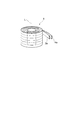
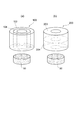
- the windings 3a and 4a used for the first superconducting coil 3 and the second superconducting coil 4 have a flat shape.
- the windings 3a and 4a are made of a sheet-like superconducting conductor.
- the winding 3a and the winding 4a are overlapped with each other with the thickness direction orthogonal to the axis L. That is, the winding 3a and the winding 4a are wound together in a state adjacent to each other in the radial direction.
- the first superconducting coil 3 formed by the winding 3a and the winding 4a has the same shape. That is, the diameter W1 of the first superconducting coil 3 is equal to the diameter W2 of the second superconducting coil 4, and the diameter W1 and the diameter W2 are respectively determined by the first superconducting coil 3 and the second superconducting coil 4. It is equal to the diameter W of the superconducting coil 5 to be formed.
- the height H1 of the first superconducting coil 3 is equal to the height H2 of the second superconducting coil 4, and the diameter H1 and the diameter H2 are respectively determined by the first superconducting coil 3 and the second superconducting coil 4. It is equal to the height H of the superconducting coil 5 to be formed.
- first axis L1 of the first superconducting coil 3 and the second axis L2 of the second superconducting coil 4 are arranged in the same position and in the same direction. That is, the first axis L1 and the second axis L2 have the same position and direction.
- the first axis L1 and the second axis L2 coincide with the axis L of the superconducting coil 5 formed by the first superconducting coil 3 and the second superconducting coil 4.
- the position of the first superconducting coil 3 and the position of the second superconducting coil 4 in the direction of the axis L are the same.
- the outer shape (or region) formed by the first superconducting coil 3 and the outer shape (or region) formed by the second superconducting coil 4 are the same, and these superconducting coils 3 and 4 are Spatial match.
- the length of the winding 3a of the first superconducting coil 3 and the length of the winding 4a of the second superconducting coil 4 are the same. In other words, the length of the winding 3a from the terminal 6 to the terminal 7 shown in FIG. 1 is equal to the length of the winding 4a from the terminal 7 to the terminal 8.
- the first superconducting coil 3 and the second superconducting coil 4 have the same inductance. In the superconducting coil 5, the space factor of the winding 3a is equal to the space factor of the winding 4a.
- the first superconducting coil 3 and the second superconducting coil 4 have the same geometric shape, and their axes L1, L2 and positions coincide with each other. Further, the length of the winding 3a of the first superconducting coil 3 and the length of the winding 4a of the second superconducting coil 4 are the same. Therefore, even when a magnetic material is present in the vicinity of the first and second superconducting coils 3 and 4, the influence exerted on the first and second superconducting coils 3 and 4 by the magnetic material is almost the same. Will be equal.
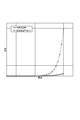
- a voltage change is less likely to appear than in a low-temperature superconducting coil.
- the voltage value increases dramatically as the current increases.
- the voltage value changes slowly and the voltage value gradually increases.
- the lower limit value of the deviation of the voltage for detecting the quench is large, when the quench is detected, the temperature at the quench point is very high and the winding may be burned out.
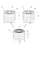
- FIG. 7 (a) in a conventional superconducting coil 100 having an outer peripheral side coil 103 and an inner peripheral side coil 104, when a ferromagnetic body 50 such as iron is present around the coil 103, Even when 104 has the same inductance, the influence of the outer coil 103 on the ferromagnetic body 50 and the influence of the inner coil 104 on the ferromagnetic body 50 are different. This is because the geometric shape and position of the outer peripheral coil 103 and the inner peripheral coil 104 are different. Further, as shown in FIG.
- the coils 203 and 204 are the same. Even if it has the following inductance, the influence of the upper coil 203 by the ferromagnetic body 50 and the influence of the lower coil 204 by the ferromagnetic body 50 are different. This is because even if the upper coil 203 and the lower coil 204 have the same geometric shape, the relative positional relationship with respect to the ferromagnetic body 50 is different.
- the quench detection device 1 even in the case of a high-temperature superconducting coil, the influence of disturbance due to the ferromagnetic body 50 can be reduced, and the detection sensitivity of the quench can be increased.
- the first superconducting coil 3 is provided between the second superconducting coils 4, the intermediate tap 17 is provided, the voltage V a between the first superconducting coil 3 of terminals 6 and 7, the The deviation from the voltage Vb between the terminals 7 and 8 of the second superconducting coil 4 can be measured with a simple configuration.
- the winding 3a of the first superconducting coil 3 and the winding 4a of the second superconducting coil 4 are adjacent to each other, the influence exerted on the first and second superconducting coils 3 and 4 by the magnetic material. Is a better match. Therefore, the influence of the disturbance can be canceled with high accuracy, and the lower limit value V TH of the voltage deviation for detecting the quench can be further reduced.
- the superconducting coil 5A of the second embodiment is different from the superconducting coil 5 of the first embodiment in that the winding 3a of the first superconducting coil 3 and the second superconducting coil 4 are different.
- the position in the radial direction with respect to the winding 4a is changed halfway. That is, the winding 3a of the first superconducting coil 3 and the winding 4a of the second superconducting coil 4 are twisted 180 degrees at a predetermined point P in a state where they are overlapped with each other. Even with such a superconducting coil 5 ⁇ / b> A, the same operations and effects as the superconducting coil 5 are achieved.
- the predetermined point P may be provided at one place or may be provided at a plurality of places.
- the superconducting coil 5B of the third embodiment differs from the superconducting coil 5 of the first embodiment in that it has a circular cross section instead of the flat windings 3a and 4a.
- the winding 13a of the first superconducting coil 3 and the winding 14a of the second superconducting coil 4 are used, and these windings 13a and 14a are twisted together. Even with such a superconducting coil 5B, the same operations and effects as the superconducting coil 5 are exhibited.
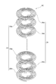
- the superconducting coil 5C according to the fourth embodiment is different from the superconducting coil 5 according to the first embodiment in that a plurality of pancakes are used instead of the co-winded flat windings 3a and 4a.
- the first superconducting coil 23 and the second superconducting coil 24 composed of the coils 23a and 24a are used, and these pancake coils 23a and 24a are alternately laminated in the direction of the axis L.
- the winding of the pancake coil 23a and the winding of the pancake coil 24a are adjacent to each other in the axis L direction. Even with such a superconducting coil 5C, the same operations and effects as the superconducting coil 5 are exhibited.
- this invention is not limited to the said embodiment.
- the first superconducting coil 3 and the second superconducting coil 4 are high-temperature superconducting coils
- they may be low-temperature superconducting coils.
- the shape of the winding wire constituting the first superconducting coil 3 and the second superconducting coil 4 may be different from those of the above embodiments. It is not limited to the case where the winding 3a of the first superconducting coil 3 and the winding 4a of the second superconducting coil 4 are co-wound, and if they have the same space factor in the same region, they are co-wound. It does not have to be.
- quench can be detected with high sensitivity.
Landscapes
- Physics & Mathematics (AREA)
- Condensed Matter Physics & Semiconductors (AREA)
- General Physics & Mathematics (AREA)
- Engineering & Computer Science (AREA)
- Power Engineering (AREA)
- Investigating Or Analyzing Materials By The Use Of Magnetic Means (AREA)
- Containers, Films, And Cooling For Superconductive Devices (AREA)
- Superconductive Dynamoelectric Machines (AREA)
Priority Applications (2)
| Application Number | Priority Date | Filing Date | Title |
|---|---|---|---|
| CN201380054248.XA CN104756205B (zh) | 2012-10-24 | 2013-08-20 | 超导线圈的失超检测装置 |
| US14/691,306 US9568569B2 (en) | 2012-10-24 | 2015-04-20 | Device for detecting quench in superconducting coil |
Applications Claiming Priority (2)
| Application Number | Priority Date | Filing Date | Title |
|---|---|---|---|
| JP2012-234723 | 2012-10-24 | ||
| JP2012234723A JP6022300B2 (ja) | 2012-10-24 | 2012-10-24 | 超電導コイルのクエンチ検出装置 |
Related Child Applications (1)
| Application Number | Title | Priority Date | Filing Date |
|---|---|---|---|
| US14/691,306 Continuation US9568569B2 (en) | 2012-10-24 | 2015-04-20 | Device for detecting quench in superconducting coil |
Publications (1)
| Publication Number | Publication Date |
|---|---|
| WO2014064994A1 true WO2014064994A1 (ja) | 2014-05-01 |
Family
ID=50544375
Family Applications (1)
| Application Number | Title | Priority Date | Filing Date |
|---|---|---|---|
| PCT/JP2013/072194 Ceased WO2014064994A1 (ja) | 2012-10-24 | 2013-08-20 | 超電導コイルのクエンチ検出装置 |
Country Status (4)
| Country | Link |
|---|---|
| US (1) | US9568569B2 (enExample) |
| JP (1) | JP6022300B2 (enExample) |
| CN (1) | CN104756205B (enExample) |
| WO (1) | WO2014064994A1 (enExample) |
Cited By (1)
| Publication number | Priority date | Publication date | Assignee | Title |
|---|---|---|---|---|
| CN111707978A (zh) * | 2020-07-09 | 2020-09-25 | 华中科技大学 | 一种超导磁体的失超检测方法、装置、设备及存储介质 |
Families Citing this family (4)
| Publication number | Priority date | Publication date | Assignee | Title |
|---|---|---|---|---|
| DE102016208226A1 (de) * | 2016-05-12 | 2017-11-16 | Bruker Biospin Ag | Kryogenfreies Magnetsystem mit magnetokalorischer Wärmesenke |
| JP6917243B2 (ja) * | 2017-08-10 | 2021-08-11 | 東芝産業機器システム株式会社 | シートコイル |
| JP7005258B2 (ja) * | 2017-10-03 | 2022-01-21 | 東芝産業機器システム株式会社 | シートコイル、変圧器 |
| JP2021019106A (ja) * | 2019-07-22 | 2021-02-15 | 株式会社日立製作所 | 伝導冷却型超伝導磁石 |
Citations (7)
| Publication number | Priority date | Publication date | Assignee | Title |
|---|---|---|---|---|
| JPH08102414A (ja) * | 1994-09-30 | 1996-04-16 | Canon Inc | 超電導装置 |
| JPH10106829A (ja) * | 1996-10-01 | 1998-04-24 | Sakutaro Yamaguchi | 超電導装置 |
| JP2000277322A (ja) * | 1999-03-26 | 2000-10-06 | Toshiba Corp | 高温超電導コイル、これを用いた高温超電導マグネットおよび高温超電導マグネットシステム |
| WO2006115126A1 (ja) * | 2005-04-19 | 2006-11-02 | Kabushiki Kaisha Toshiba | 超電導コイルのクエンチ検出方法と装置および超電導電力貯蔵装置 |
| JP2007234689A (ja) * | 2006-02-28 | 2007-09-13 | Hitachi Ltd | 多コイル系超伝導マグネット |
| JP2012023168A (ja) * | 2010-07-14 | 2012-02-02 | Hitachi Ltd | 超電導コイル、超電導マグネットおよびその運転方法 |
| JP2012238628A (ja) * | 2011-05-10 | 2012-12-06 | Hitachi Ltd | 並列巻線を有する超電導磁石および超電導磁石システム |
Family Cites Families (11)
| Publication number | Priority date | Publication date | Assignee | Title |
|---|---|---|---|---|
| JPS6392006A (ja) * | 1986-10-07 | 1988-04-22 | Mitsubishi Electric Corp | 超電導装置の電圧検出装置 |
| US4996472A (en) * | 1989-08-31 | 1991-02-26 | Westinghouse Electric Corp. | Passive superconducting quench detection sensor |
| JP2842281B2 (ja) * | 1994-03-29 | 1998-12-24 | 住友電気工業株式会社 | 酸化物超電導磁束トランスとその製造方法 |
| JPH0984252A (ja) | 1995-09-12 | 1997-03-28 | Mitsubishi Electric Corp | 超電導コイルクエンチ検出装置 |
| US5739997A (en) * | 1995-11-30 | 1998-04-14 | General Electric Company | Superconducting-magnet electrical circuit offering quench protection |
| US5683179A (en) * | 1995-12-15 | 1997-11-04 | Northrop Grumman Corporation | Apparatus and method for thermoluminescent quench detection for superconducting devices |
| US5892644A (en) * | 1997-11-20 | 1999-04-06 | The University Of Chicago | Passive fault current limiting device |
| US6445555B1 (en) * | 1999-11-24 | 2002-09-03 | American Superconductor Corporation | Method and apparatus for discharging a superconducting magnet |
| US7615998B2 (en) | 2007-01-09 | 2009-11-10 | General Electric Company | Method and apparatus for actively controlling quench protection of a superconducting magnet |
| US8542015B2 (en) * | 2011-01-19 | 2013-09-24 | General Electric Company | Apparatus and method for protecting a magnetic resonance imaging magnet during quench |
| GB201117381D0 (en) * | 2011-10-10 | 2011-11-23 | Rolls Royce Plc | A superconducting fault current limiter |
-
2012
- 2012-10-24 JP JP2012234723A patent/JP6022300B2/ja active Active
-
2013
- 2013-08-20 WO PCT/JP2013/072194 patent/WO2014064994A1/ja not_active Ceased
- 2013-08-20 CN CN201380054248.XA patent/CN104756205B/zh active Active
-
2015
- 2015-04-20 US US14/691,306 patent/US9568569B2/en active Active
Patent Citations (7)
| Publication number | Priority date | Publication date | Assignee | Title |
|---|---|---|---|---|
| JPH08102414A (ja) * | 1994-09-30 | 1996-04-16 | Canon Inc | 超電導装置 |
| JPH10106829A (ja) * | 1996-10-01 | 1998-04-24 | Sakutaro Yamaguchi | 超電導装置 |
| JP2000277322A (ja) * | 1999-03-26 | 2000-10-06 | Toshiba Corp | 高温超電導コイル、これを用いた高温超電導マグネットおよび高温超電導マグネットシステム |
| WO2006115126A1 (ja) * | 2005-04-19 | 2006-11-02 | Kabushiki Kaisha Toshiba | 超電導コイルのクエンチ検出方法と装置および超電導電力貯蔵装置 |
| JP2007234689A (ja) * | 2006-02-28 | 2007-09-13 | Hitachi Ltd | 多コイル系超伝導マグネット |
| JP2012023168A (ja) * | 2010-07-14 | 2012-02-02 | Hitachi Ltd | 超電導コイル、超電導マグネットおよびその運転方法 |
| JP2012238628A (ja) * | 2011-05-10 | 2012-12-06 | Hitachi Ltd | 並列巻線を有する超電導磁石および超電導磁石システム |
Cited By (1)
| Publication number | Priority date | Publication date | Assignee | Title |
|---|---|---|---|---|
| CN111707978A (zh) * | 2020-07-09 | 2020-09-25 | 华中科技大学 | 一种超导磁体的失超检测方法、装置、设备及存储介质 |
Also Published As
| Publication number | Publication date |
|---|---|
| US9568569B2 (en) | 2017-02-14 |
| JP6022300B2 (ja) | 2016-11-09 |
| JP2014086584A (ja) | 2014-05-12 |
| US20150226814A1 (en) | 2015-08-13 |
| CN104756205A (zh) | 2015-07-01 |
| CN104756205B (zh) | 2017-08-22 |
Similar Documents
| Publication | Publication Date | Title |
|---|---|---|
| JP6022300B2 (ja) | 超電導コイルのクエンチ検出装置 | |
| JP6455811B2 (ja) | 電流検出用コイル | |
| RU2581598C2 (ru) | Индуктивный ограничитель тока утечки с разделенной системой вторичной катушки | |
| US11742139B2 (en) | Current transformer | |
| JP2007155427A (ja) | 交流電流検出用コイル | |
| CN102208243A (zh) | 电感器 | |
| JP2019021673A (ja) | 三相リアクトル | |
| JP2013160638A (ja) | 電流検出器 | |
| US9197060B2 (en) | Inductive fault current limiter with divided primary coil configuration | |
| JP2016017767A (ja) | ロゴスキーコイルおよび電流測定器 | |
| JP2014086584A5 (enExample) | ||
| US20160268037A1 (en) | Stationary Induction Electric Apparatus and Method for Making the Same | |
| JP2010266209A (ja) | 電流センサ | |
| JP4978701B2 (ja) | トランスおよびトランス装置 | |
| JP6220554B2 (ja) | 超電導コイルのクエンチ検出装置及びクエンチ検出方法 | |
| JP5937025B2 (ja) | 超電導磁気シールド装置 | |
| JP7029920B2 (ja) | 変圧器 | |
| JP4532034B2 (ja) | 零相変流器 | |
| JP5405327B2 (ja) | 単相変圧器及びそれを用いた配電系統 | |
| KR102774591B1 (ko) | 차동 코일을 이용한 간섭 객체 검출 센서 | |
| JP6426903B2 (ja) | 零相変流器 | |
| JPH01102902A (ja) | 電磁線輪 | |
| JP2016004950A (ja) | 静止誘導電気機器 | |
| JP2018194419A (ja) | 直線型差動変圧器 | |
| CN104465057B (zh) | 一种筒状导体电流互感器 |
Legal Events
| Date | Code | Title | Description |
|---|---|---|---|
| 121 | Ep: the epo has been informed by wipo that ep was designated in this application |
Ref document number: 13848909 Country of ref document: EP Kind code of ref document: A1 |
|
| NENP | Non-entry into the national phase |
Ref country code: DE |
|
| 122 | Ep: pct application non-entry in european phase |
Ref document number: 13848909 Country of ref document: EP Kind code of ref document: A1 |