WO2014064994A1 - 超電導コイルのクエンチ検出装置 - Google Patents
超電導コイルのクエンチ検出装置 Download PDFInfo
- Publication number
- WO2014064994A1 WO2014064994A1 PCT/JP2013/072194 JP2013072194W WO2014064994A1 WO 2014064994 A1 WO2014064994 A1 WO 2014064994A1 JP 2013072194 W JP2013072194 W JP 2013072194W WO 2014064994 A1 WO2014064994 A1 WO 2014064994A1
- Authority
- WO
- WIPO (PCT)
- Prior art keywords
- superconducting coil
- winding
- coil
- superconducting
- same
- Prior art date
- Legal status (The legal status is an assumption and is not a legal conclusion. Google has not performed a legal analysis and makes no representation as to the accuracy of the status listed.)
- Ceased
Links
Images


Classifications
-
- G—PHYSICS
- G01—MEASURING; TESTING
- G01R—MEASURING ELECTRIC VARIABLES; MEASURING MAGNETIC VARIABLES
- G01R33/00—Arrangements or instruments for measuring magnetic variables
- G01R33/12—Measuring magnetic properties of articles or specimens of solids or fluids
- G01R33/1238—Measuring superconductive properties
-
- H—ELECTRICITY
- H01—ELECTRIC ELEMENTS
- H01F—MAGNETS; INDUCTANCES; TRANSFORMERS; SELECTION OF MATERIALS FOR THEIR MAGNETIC PROPERTIES
- H01F6/00—Superconducting magnets; Superconducting coils
- H01F6/02—Quenching; Protection arrangements during quenching
-
- G—PHYSICS
- G01—MEASURING; TESTING
- G01K—MEASURING TEMPERATURE; MEASURING QUANTITY OF HEAT; THERMALLY-SENSITIVE ELEMENTS NOT OTHERWISE PROVIDED FOR
- G01K1/00—Details of thermometers not specially adapted for particular types of thermometer
-
- H—ELECTRICITY
- H01—ELECTRIC ELEMENTS
- H01F—MAGNETS; INDUCTANCES; TRANSFORMERS; SELECTION OF MATERIALS FOR THEIR MAGNETIC PROPERTIES
- H01F1/00—Magnets or magnetic bodies characterised by the magnetic materials therefor; Selection of materials for their magnetic properties
Definitions
- the present invention relates to a quench detection device for a superconducting coil.
- a device described in Patent Document 1 is known as a quench detection device for a superconducting coil.
- the superconducting coil of this device is composed of a first superconducting coil and a second superconducting coil connected in series.
- the first superconducting coil and the second superconducting coil are connected at the midpoint of the superconducting coil, that is, the midpoint of the entire coil.
- the voltage between the terminals of the first superconducting coil and the voltage between the terminals of the second superconducting coil are measured, and a deviation of these measured values is obtained to detect a minute voltage generated with quenching. is doing.
- An object of the present invention is to provide a quench detection device for a superconducting coil capable of detecting quench with high sensitivity.
- the superconducting coil quench detection apparatus includes a first superconducting coil and a second superconducting coil connected in series, and the first superconducting coil and the second superconducting coil are the same.
- the first axis of the first superconducting coil and the second axis of the second superconducting coil are arranged in the same position and in the same direction, and the first superconducting in that direction.
- the position of the coil and the position of the second superconducting coil are the same, and the winding length of the first superconducting coil and the winding length of the second superconducting coil are the same.
- the first superconducting coil and the second superconducting coil have the same shape. Furthermore, the first axis of the first superconducting coil and the second axis of the second superconducting coil are arranged in the same position and in the same direction, and the position of the first superconducting coil in that direction The position of the second superconducting coil is the same. As described above, the first superconducting coil and the second superconducting coil have the same geometric shape, and their axes and positions coincide with each other. Furthermore, the winding length of the first superconducting coil and the winding length of the second superconducting coil are the same.
- the influence exerted on the first and second superconducting coils by the magnetic material is substantially equal. Therefore, in the deviation between the voltage between the terminals of the first superconducting coil and the voltage between the terminals of the second superconducting coil, the influence of the disturbance due to the magnetic substance is almost offset. Therefore, the lower limit value of the deviation of the voltage at which quenching can be detected becomes small, and quenching can be detected with high sensitivity.
- an intermediate tap may be provided between the first superconducting coil and the second superconducting coil.
- the winding of the first superconducting coil and the winding of the second superconducting coil may be adjacent to each other. According to this configuration, the effects exerted on the first and second superconducting coils by the magnetic body are better matched. Therefore, the influence of the disturbance can be canceled with high accuracy, and the lower limit value of the deviation of the voltage for detecting the quench can be further reduced.
- the winding of the first superconducting coil and the winding of the second superconducting coil may be wound together. Quench can be detected with high sensitivity by a simple manufacturing method.
- the winding of the first superconducting coil and the winding of the second superconducting coil have a flat shape and may be overlapped with each other.
- the positions of the first superconducting coil and the second superconducting coil may be switched in the middle in the radial direction.
- the winding of the first superconducting coil and the winding of the second superconducting coil have a circular cross section and may be twisted together.
- first superconducting coil winding and the second superconducting coil winding may be formed by alternately stacking a plurality of pancake coils in the axial direction of the superconducting coil.
- quench can be detected with high sensitivity.
- the quench detection device 1 includes a DC power source 2 that outputs a DC voltage, and a first superconducting coil 3 and a second superconducting coil 4 connected to the DC power source 2.
- the first superconducting coil 3 and the second superconducting coil 4 are connected in series.
- the first superconducting coil 3 and the second superconducting coil 4 are high-temperature superconducting coils made of a high-temperature superconducting conductor such as copper oxide containing yttrium.
- the first superconducting coil 3 and the second superconducting coil 4 constitute a superconducting coil 5.
- the superconducting coil 5 is mounted on a superconducting magnet device and is mainly used as an electromagnet.
- a voltage tap 16 is connected to one terminal 6 of the first superconducting coil 3.
- a voltage tap (intermediate tap) 17 is connected to an intermediate terminal 7 between the first superconducting coil 3 and the second superconducting coil 4.
- a voltage tap 18 is connected to the other terminal of the second superconducting coil 4.
- the quench detection device 1 includes a detector 10 for detecting a quench in the superconducting coil 5.
- the detector 10 has an input terminal 11 connected to the voltage tap 16, an input terminal 12 connected to the voltage tap 17, and an input terminal 13 connected to the voltage tap 18.
- Detector 10 measures a first voltage V a between the first superconducting coil 3 terminals 6,7.
- Detector 10 measures a second voltage V b between the terminals 7 and 8 of the second superconducting coil 4.
- the detector 10 stores a threshold value V TH for determining the occurrence of quenching.
- Detector 10 on the basis of the deviation between the first voltage V a and the second voltage V b, determines the presence or absence of occurrence of the quench.
- the detector 10 determines that quenching has occurred in the superconducting coil 5 when the following expression (1) is satisfied.
- the windings 3a and 4a used for the first superconducting coil 3 and the second superconducting coil 4 have a flat shape.
- the windings 3a and 4a are made of a sheet-like superconducting conductor.
- the winding 3a and the winding 4a are overlapped with each other with the thickness direction orthogonal to the axis L. That is, the winding 3a and the winding 4a are wound together in a state adjacent to each other in the radial direction.
- the first superconducting coil 3 formed by the winding 3a and the winding 4a has the same shape. That is, the diameter W1 of the first superconducting coil 3 is equal to the diameter W2 of the second superconducting coil 4, and the diameter W1 and the diameter W2 are respectively determined by the first superconducting coil 3 and the second superconducting coil 4. It is equal to the diameter W of the superconducting coil 5 to be formed.
- the height H1 of the first superconducting coil 3 is equal to the height H2 of the second superconducting coil 4, and the diameter H1 and the diameter H2 are respectively determined by the first superconducting coil 3 and the second superconducting coil 4. It is equal to the height H of the superconducting coil 5 to be formed.
- first axis L1 of the first superconducting coil 3 and the second axis L2 of the second superconducting coil 4 are arranged in the same position and in the same direction. That is, the first axis L1 and the second axis L2 have the same position and direction.
- the first axis L1 and the second axis L2 coincide with the axis L of the superconducting coil 5 formed by the first superconducting coil 3 and the second superconducting coil 4.
- the position of the first superconducting coil 3 and the position of the second superconducting coil 4 in the direction of the axis L are the same.
- the outer shape (or region) formed by the first superconducting coil 3 and the outer shape (or region) formed by the second superconducting coil 4 are the same, and these superconducting coils 3 and 4 are Spatial match.
- the length of the winding 3a of the first superconducting coil 3 and the length of the winding 4a of the second superconducting coil 4 are the same. In other words, the length of the winding 3a from the terminal 6 to the terminal 7 shown in FIG. 1 is equal to the length of the winding 4a from the terminal 7 to the terminal 8.
- the first superconducting coil 3 and the second superconducting coil 4 have the same inductance. In the superconducting coil 5, the space factor of the winding 3a is equal to the space factor of the winding 4a.
- the first superconducting coil 3 and the second superconducting coil 4 have the same geometric shape, and their axes L1, L2 and positions coincide with each other. Further, the length of the winding 3a of the first superconducting coil 3 and the length of the winding 4a of the second superconducting coil 4 are the same. Therefore, even when a magnetic material is present in the vicinity of the first and second superconducting coils 3 and 4, the influence exerted on the first and second superconducting coils 3 and 4 by the magnetic material is almost the same. Will be equal.
- a voltage change is less likely to appear than in a low-temperature superconducting coil.
- the voltage value increases dramatically as the current increases.
- the voltage value changes slowly and the voltage value gradually increases.
- the lower limit value of the deviation of the voltage for detecting the quench is large, when the quench is detected, the temperature at the quench point is very high and the winding may be burned out.
- FIG. 7 (a) in a conventional superconducting coil 100 having an outer peripheral side coil 103 and an inner peripheral side coil 104, when a ferromagnetic body 50 such as iron is present around the coil 103, Even when 104 has the same inductance, the influence of the outer coil 103 on the ferromagnetic body 50 and the influence of the inner coil 104 on the ferromagnetic body 50 are different. This is because the geometric shape and position of the outer peripheral coil 103 and the inner peripheral coil 104 are different. Further, as shown in FIG.
- the coils 203 and 204 are the same. Even if it has the following inductance, the influence of the upper coil 203 by the ferromagnetic body 50 and the influence of the lower coil 204 by the ferromagnetic body 50 are different. This is because even if the upper coil 203 and the lower coil 204 have the same geometric shape, the relative positional relationship with respect to the ferromagnetic body 50 is different.
- the quench detection device 1 even in the case of a high-temperature superconducting coil, the influence of disturbance due to the ferromagnetic body 50 can be reduced, and the detection sensitivity of the quench can be increased.
- the first superconducting coil 3 is provided between the second superconducting coils 4, the intermediate tap 17 is provided, the voltage V a between the first superconducting coil 3 of terminals 6 and 7, the The deviation from the voltage Vb between the terminals 7 and 8 of the second superconducting coil 4 can be measured with a simple configuration.
- the winding 3a of the first superconducting coil 3 and the winding 4a of the second superconducting coil 4 are adjacent to each other, the influence exerted on the first and second superconducting coils 3 and 4 by the magnetic material. Is a better match. Therefore, the influence of the disturbance can be canceled with high accuracy, and the lower limit value V TH of the voltage deviation for detecting the quench can be further reduced.
- the superconducting coil 5A of the second embodiment is different from the superconducting coil 5 of the first embodiment in that the winding 3a of the first superconducting coil 3 and the second superconducting coil 4 are different.
- the position in the radial direction with respect to the winding 4a is changed halfway. That is, the winding 3a of the first superconducting coil 3 and the winding 4a of the second superconducting coil 4 are twisted 180 degrees at a predetermined point P in a state where they are overlapped with each other. Even with such a superconducting coil 5 ⁇ / b> A, the same operations and effects as the superconducting coil 5 are achieved.
- the predetermined point P may be provided at one place or may be provided at a plurality of places.
- the superconducting coil 5B of the third embodiment differs from the superconducting coil 5 of the first embodiment in that it has a circular cross section instead of the flat windings 3a and 4a.
- the winding 13a of the first superconducting coil 3 and the winding 14a of the second superconducting coil 4 are used, and these windings 13a and 14a are twisted together. Even with such a superconducting coil 5B, the same operations and effects as the superconducting coil 5 are exhibited.
- the superconducting coil 5C according to the fourth embodiment is different from the superconducting coil 5 according to the first embodiment in that a plurality of pancakes are used instead of the co-winded flat windings 3a and 4a.
- the first superconducting coil 23 and the second superconducting coil 24 composed of the coils 23a and 24a are used, and these pancake coils 23a and 24a are alternately laminated in the direction of the axis L.
- the winding of the pancake coil 23a and the winding of the pancake coil 24a are adjacent to each other in the axis L direction. Even with such a superconducting coil 5C, the same operations and effects as the superconducting coil 5 are exhibited.
- this invention is not limited to the said embodiment.
- the first superconducting coil 3 and the second superconducting coil 4 are high-temperature superconducting coils
- they may be low-temperature superconducting coils.
- the shape of the winding wire constituting the first superconducting coil 3 and the second superconducting coil 4 may be different from those of the above embodiments. It is not limited to the case where the winding 3a of the first superconducting coil 3 and the winding 4a of the second superconducting coil 4 are co-wound, and if they have the same space factor in the same region, they are co-wound. It does not have to be.
- quench can be detected with high sensitivity.
Landscapes
- Physics & Mathematics (AREA)
- Engineering & Computer Science (AREA)
- Power Engineering (AREA)
- Condensed Matter Physics & Semiconductors (AREA)
- General Physics & Mathematics (AREA)
- Investigating Or Analyzing Materials By The Use Of Magnetic Means (AREA)
- Containers, Films, And Cooling For Superconductive Devices (AREA)
- Superconductive Dynamoelectric Machines (AREA)
Abstract
本発明の一側面の超電導コイルのクエンチ検出装置は、直列に接続された第1の超電導コイルと第2の超電導コイルとを備える。第1の超電導コイルと第2の超電導コイルとは、同一の形状をなしている。第1の超電導コイルの第1の軸線と第2の超電導コイルの第2の軸線とは、同一の位置および同一の方向に配置されると共に、その方向における第1の超電導コイルの位置と第2の超電導コイルの位置とは同一である。第1の超電導コイルの巻線の長さと第2の超電導コイルの巻線の長さとは同一である。
Description
本発明は、超電導コイルのクエンチ検出装置に関する。
従来、超電導コイルのクエンチ検出装置として、たとえば特許文献1に記載された装置が知られている。この装置の超電導コイルは、直列に接続された第1の超電導コイルと第2の超電導コイルとから構成されている。第1の超電導コイルと第2の超電導コイルとは、超電導コイルの中点、すなわちコイル全体の中点で接続されている。そして、第1の超電導コイルの端子間の電圧と、第2の超電導コイルの端子間の電圧とを測定し、これらの測定値の偏差を求めることにより、クエンチに伴って発生する微小電圧を検出している。
しかしながら、上述した従来の装置では、超電導コイルの近傍に鉄などの磁性体があると、この磁性体が外乱の要因となり得る。磁性体の存在によって超電導コイルの端子間の電圧が影響を受けた場合、クエンチが発生していない状態においても、第1の超電導コイルの端子間の電圧と、第2の超電導コイルの端子間の電圧とがキャンセルされずに(偏差がゼロにならずに)、電圧が残ってしまう。その結果、クエンチを検出できる電圧の偏差の下限値が大きくなり、クエンチの検出感度が悪化してしまう。
クエンチの検出感度の悪化により、クエンチの検出が遅れ、超電導コイルの焼損リスクが高まる。このように、従来、クエンチを高感度で検出することは困難であった。
本発明は、クエンチを高感度で検出することができる超電導コイルのクエンチ検出装置を提供すること目的とする。
本発明の一側面の超電導コイルのクエンチ検出装置は、直列に接続された第1の超電導コイルと第2の超電導コイルとを備え、第1の超電導コイルと第2の超電導コイルとは、同一の形状をなしており、第1の超電導コイルの第1の軸線と第2の超電導コイルの第2の軸線とは、同一の位置および同一の方向に配置されると共に、その方向における第1の超電導コイルの位置と第2の超電導コイルの位置とは同一であり、第1の超電導コイルの巻線の長さと第2の超電導コイルの巻線の長さとは同一である。
この超電導コイルのクエンチ検出装置では、第1の超電導コイルと第2の超電導コイルとは、同一の形状をなしている。さらに、第1の超電導コイルの第1の軸線と第2の超電導コイルの第2の軸線とは、同一の位置および同一の方向に配置されると共に、その方向における第1の超電導コイルの位置と第2の超電導コイルの位置とは同一である。このように、第1の超電導コイルと第2の超電導コイルとは、幾何学形状が同一であり、それぞれの軸線および位置が一致している。さらに、第1の超電導コイルの巻線の長さと第2の超電導コイルの巻線の長さとは同一である。よって、第1および第2の超電導コイルの近傍に磁性体が存在している場合であっても、磁性体によって第1および第2の超電導コイルに及ぼされる影響は、ほぼ等しくなる。よって、第1の超電導コイルの端子間の電圧と、第2の超電導コイルの端子間の電圧との偏差において、磁性体による外乱の影響がほぼ相殺される。そのため、クエンチを検出できる電圧の偏差の下限値が小さくなり、クエンチを高感度で検出することができる。
また、第1の超電導コイルと第2の超電導コイルとの間には、中間タップが設けられていてもよい。この構成によれば、第1の超電導コイルの端子間の電圧と、第2の超電導コイルの端子間の電圧との偏差を簡易な構成で測定することができる。
また、第1の超電導コイルの巻線と第2の超電導コイルの巻線とは、隣り合っていてもよい。この構成によれば、磁性体によって第1および第2の超電導コイルに及ぼされる影響が、より良く一致する。よって、外乱の影響を精度良く相殺することができ、クエンチを検出する電圧の偏差の下限値をさらに小さくできる。
また、第1の超電導コイルの巻線と第2の超電導コイルの巻線とは、共巻きされていてもよい。簡易な製造方法により、クエンチを高感度で検出することができる。
また、第1の超電導コイルの巻線と第2の超電導コイルの巻線とは、扁平状をなしており、互いに重ね合わされていてもよい。
また、第1の超電導コイルの巻線と第2の超電導コイルの巻線とは、径方向における位置が途中で入れ替わっていてもよい。
また、第1の超電導コイルの巻線と第2の超電導コイルの巻線とは、断面円形状をなしており、互いに撚り合わされていてもよい。
また、第1の超電導コイルの巻線と第2の超電導コイルの巻線とは、複数のパンケーキコイルが超電導コイルの軸線方向に交互に積層されてなってもよい。
本発明の一側面によれば、クエンチを高感度で検出することができる。
以下、本発明の実施形態について、図面を参照しながら説明する。なお、図面の説明において同一要素には同一符号を付し、重複する説明は省略する。
図1~図3を参照して、第1実施形態のクエンチ検出装置1について説明する。まず、図1を参照して、クエンチ検出装置1の回路構成について説明する。クエンチ検出装置1は、直流電圧を出力する直流電源2と、直流電源2に接続された第1の超電導コイル3および第2の超電導コイル4とを備えている。第1の超電導コイル3と第2の超電導コイル4とは、直列に接続されている。第1の超電導コイル3と第2の超電導コイル4は、たとえばイットリウムを含む銅酸化物などの高温超電導導体からなる、高温超電導コイルである。第1の超電導コイル3および第2の超電導コイル4によって、超電導コイル5が構成されている。超電導コイル5は、超電導マグネット装置に搭載されて、主に電磁石として利用される。
第1の超電導コイル3の一方の端子6には、電圧タップ16が接続されている。第1の超電導コイル3と第2の超電導コイル4との中間の端子7には、電圧タップ(中間タップ)17が接続されている。第2の超電導コイル4の他方の端子には、電圧タップ18が接続されている。
クエンチ検出装置1は、超電導コイル5におけるクエンチを検出するための検出器10を備えている。検出器10は、電圧タップ16に接続される入力端子11と、電圧タップ17に接続される入力端子12と、電圧タップ18に接続される入力端子13とを有している。検出器10は、第1の超電導コイル3の端子6,7間の第1の電圧Vaを測定する。検出器10は、第2の超電導コイル4の端子7,8間の第2の電圧Vbを測定する。検出器10は、クエンチの発生を判定するための閾値VTHを記憶している。検出器10は、第1の電圧Vaと第2の電圧Vbとの偏差に基づいて、クエンチの発生の有無を判定する。
より詳しくは、検出器10は、下記式(1)が満たされた場合に、超電導コイル5にクエンチが発生したと判定する。
|Va-Vb|>VTH・・・(1)
|Va-Vb|>VTH・・・(1)
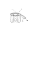
図2に示されるように、第1の超電導コイル3および第2の超電導コイル4に用いられる巻線3a,4aは、扁平状をなしている。言い換えれば、巻線3a,4aは、シート状の超電導導体からなる。巻線3aと巻線4aとは、その厚さ方向が軸線Lに直交する状態で、互いに重ね合されている。すなわち、巻線3aと巻線4aとは、径方向に隣り合った状態で、共巻きされている。
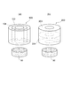
図3に示されるように、共巻きされた巻線3aと巻線4aとを概念的に分離して考えた場合、巻線3aによって形成される第1の超電導コイル3と、巻線4aによって形成される第2の超電導コイル4とは、同一の形状をなしている。すなわち、第1の超電導コイル3の直径W1と、第2の超電導コイル4の直径W2とは等しく、直径W1と直径W2のそれぞれは、第1の超電導コイル3と第2の超電導コイル4とによって形成される超電導コイル5の直径Wに等しい。第1の超電導コイル3の高さH1と、第2の超電導コイル4の高さH2とは等しく、直径H1と直径H2のそれぞれは、第1の超電導コイル3と第2の超電導コイル4とによって形成される超電導コイル5の高さHに等しい。
さらに、第1の超電導コイル3の第1の軸線L1と、第2の超電導コイル4の第2の軸線L2とは、同一の位置および同一の方向に配置される。すなわち、第1の軸線L1と第2の軸線L2とは、位置および方向が一致する。第1の軸線L1と第2の軸線L2とは、第1の超電導コイル3と第2の超電導コイル4とによって形成される超電導コイル5の軸線Lに一致する。軸線Lの方向における第1の超電導コイル3の位置と第2の超電導コイル4の位置とは同一である。言い換えれば、第1の超電導コイル3によって形成される外形(または領域)と、第2の超電導コイル4によって形成される外形(または領域)とは同一であり、これらの超電導コイル3,4は、空間的に一致する。
第1の超電導コイル3の巻線3aの長さと第2の超電導コイル4の巻線4aの長さとは、同一である。言い換えれば、図1に示す端子6から端子7までの巻線3aの長さと、端子7から端子8までの巻線4aの長さは、等しくなっている。第1の超電導コイル3と第2の超電導コイル4とは、同一のインダクタンスを有する。超電導コイル5において、巻線3aの占積率と巻線4aの占積率とは、等しくなっている。
超電導コイル5のクエンチ検出装置1によれば、第1の超電導コイル3と第2の超電導コイル4とは、幾何学形状が同一であり、それぞれの軸線L1,L2および位置が一致している。さらに、第1の超電導コイル3の巻線3aの長さと第2の超電導コイル4の巻線4aの長さとは同一である。よって、第1および第2の超電導コイル3,4の近傍に磁性体が存在している場合であっても、磁性体によって第1および第2の超電導コイル3,4に及ぼされる影響は、ほぼ等しくなる。よって、第1の超電導コイル3の端子6,7間の電圧Vaと、第2の超電導コイル4の端子7,8間の電圧Vbとの偏差において、磁性体による外乱の影響がほぼ相殺される。そのため、クエンチを検出する電圧の偏差の下限値VTHが小さくされ、クエンチを高感度で検出することができる。その結果として、クエンチを素早く検出することができ、コイルの超電導コイルの焼損リスクを低減することができる。
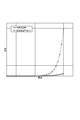
一般に、高温超電導コイルにおいては、低温超電導コイルに比して、電圧の変化が表れにくい。図4に示されるように、ニオブチタンなどを導体に用いる低温超電導コイルでは、電流の増加に伴って、電圧値は劇的に上昇する。一方、高温超電導コイルでは、電流が増加しても、電圧値は電圧の変化は緩やかであり、電圧値は漸増する程度である。このような高温超電導コイルでは、クエンチを検出する電圧の偏差の下限値が大きいと、クエンチが検出されたときには、クエンチ箇所の温度が非常に高くなっており、巻線が焼き切れるおそれがある。
たとえば、図7(a)に示されるように、外周側コイル103と内周側コイル104とを有する従来の超電導コイル100では、鉄等の強磁性体50が周囲に存在する場合、コイル103,104が同一のインダクタンスを有する場合であっても、外周側コイル103が強磁性体50によって受ける影響と、内周側コイル104が強磁性体50によって受ける影響は異なる。これは、外周側コイル103と内周側コイル104との幾何学的形状および位置が異なるからである。また、図7(b)に示されるように、上段コイル203と下段コイル204とを有する従来の超電導コイル200では、鉄等の強磁性体50が周囲に存在する場合、コイル203,204が同一のインダクタンスを有する場合であっても、上段コイル203が強磁性体50によって受ける影響と、下段コイル204が強磁性体50によって受ける影響は異なる。これは、上段コイル203と下段コイル204との幾何学的形状が同じであっても、強磁性体50に対する相対位置関係が異なるからである。
よって、従来の超電導コイル100または超電導コイル200では、強磁性体50による外乱の影響が大きく、「Va-Vb」の絶対値がゼロにならず、一定の値を示してしまう。よって、クエンチを検出する電圧の偏差の下限値を大きくせざるを得ず、クエンチの検出感度が悪かった。
クエンチ検出装置1によれば、高温超電導コイルの場合でも、強磁性体50による外乱の影響を小さくすることができ、クエンチの検出感度が高められる。
また、第1の超電導コイル3と第2の超電導コイル4との間には、中間タップ17が設けられているため、第1の超電導コイル3の端子6,7間の電圧Vaと、第2の超電導コイル4の端子7,8間の電圧Vbとの偏差を簡易な構成で測定することができる。
また、第1の超電導コイル3の巻線3aと第2の超電導コイル4の巻線4aとは、隣り合っているため、磁性体によって第1および第2の超電導コイル3,4に及ぼされる影響が、より良く一致する。よって、外乱の影響を精度良く相殺することができ、クエンチを検出する電圧の偏差の下限値VTHをさらに小さくできる。
また、第1の超電導コイル3の巻線3aと第2の超電導コイル4の巻線4aとは、共巻きされているため、簡易な製造方法により、クエンチを高感度で検出することができる。
次に、図5および図6を参照して、超電導コイルの他の実施形態について説明する。
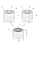
図5(a)に示されるように、第2実施形態の超電導コイル5Aが第1実施形態の超電導コイル5と違う点は、第1の超電導コイル3の巻線3aと第2の超電導コイル4の巻線4aとの径方向における位置が、途中で入れ替わっている点である。すなわち、第1の超電導コイル3の巻線3aと第2の超電導コイル4の巻線4aとは、互いに重ね合された状態で、所定の点Pにおいて180度捻られている。このような超電導コイル5Aによっても、超電導コイル5と同様の作用・効果が奏される。また、共巻きされる巻線3aと巻線4aとにおいて、内周側の巻線の長さが外周側の巻線の長さよりも短くなってしまうことを回避できるので、巻線3aと巻線4aとの長さを一致させやすい。所定の点Pは、1箇所に設けられてもよく、複数箇所に設けられてもよい。
図5(b)に示されるように、第3実施形態の超電導コイル5Bが第1実施形態の超電導コイル5と違う点は、扁平状の巻線3a,4aに代えて、断面円形状をなす第1の超電導コイル3の巻線13aおよび第2の超電導コイル4の巻線14aを用い、これらの巻線13a,14aを互いに撚り合わせた点である。このような超電導コイル5Bによっても、超電導コイル5と同様の作用・効果が奏される。
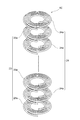
図6に示されるように、第4実施形態の超電導コイル5Cが第1実施形態の超電導コイル5と違う点は、共巻きされた扁平状の巻線3a,4aに代えて、複数のパンケーキコイル23a,24aからなる第1の超電導コイル23および第2の超電導コイル24を用い、これらのパンケーキコイル23a,24aを軸線L方向に交互に積層した点である。第1の超電導コイル23と第2の超電導コイル24とにおいても、パンケーキコイル23aの巻線とパンケーキコイル24aの巻線とが、軸線L方向において隣り合っている。このような超電導コイル5Cによっても、超電導コイル5と同様の作用・効果が奏される。
以上、本発明の実施形態について説明したが、本発明は上記実施形態に限られるものではない。たとえば、上記実施形態では、第1の超電導コイル3および第2の超電導コイル4が高温超電導コイルである場合について説明したが、低温超電導コイルであってもよい。第1の超電導コイル3および第2の超電導コイル4を構成する巻線の形状は、上記各実施形態とは異なってもよい。第1の超電導コイル3の巻線3aと第2の超電導コイル4の巻線4aとが共巻きされる場合に限られず、同一領域内において同一の占積率になっていれば、共巻きされていなくてもよい。
本発明の一側面によれば、クエンチを高感度で検出することができる。
1…クエンチ検出装置、3…第1の超電導コイル、3a…巻線、4…第2の超電導コイル、4a…巻線、5…超電導コイル、L1…第1の軸線、L2…第2の軸線。
Claims (8)
- 直列に接続された第1の超電導コイルと第2の超電導コイルとを備え、
前記第1の超電導コイルと前記第2の超電導コイルとは、同一の形状をなしており、
前記第1の超電導コイルの第1の軸線と前記第2の超電導コイルの第2の軸線とは、同一の位置および同一の方向に配置されると共に、前記方向における前記第1の超電導コイルの位置と前記第2の超電導コイルの位置とは同一であり、
前記第1の超電導コイルの巻線の長さと前記第2の超電導コイルの巻線の長さとは同一である、超電導コイルのクエンチ検出装置。 - 前記第1の超電導コイルと前記第2の超電導コイルとの間には、中間タップが設けられている、請求項1記載の超電導コイルのクエンチ検出装置。
- 前記第1の超電導コイルの巻線と前記第2の超電導コイルの巻線とは、隣り合っている、請求項1または2記載の超電導コイルのクエンチ検出装置。
- 前記第1の超電導コイルの巻線と前記第2の超電導コイルの巻線とは、共巻きされている、請求項3記載の超電導コイルのクエンチ検出装置。
- 前記第1の超電導コイルの巻線と前記第2の超電導コイルの巻線とは、扁平状をなしており、互いに重ね合わされている、請求項4記載の超電導コイルのクエンチ検出装置。
- 前記第1の超電導コイルの巻線と前記第2の超電導コイルの巻線とは、径方向における位置が途中で入れ替わっている、請求項5記載の超電導コイルのクエンチ検出装置。
- 前記第1の超電導コイルの巻線と前記第2の超電導コイルの巻線とは、断面円形状をなしており、互いに撚り合わされている、請求項4記載の超電導コイルのクエンチ検出装置。
- 前記第1の超電導コイルの巻線と前記第2の超電導コイルの巻線とは、複数のパンケーキコイルが前記方向に交互に積層されてなる、請求項3記載の超電導コイルのクエンチ検出装置。
Priority Applications (2)
| Application Number | Priority Date | Filing Date | Title |
|---|---|---|---|
| CN201380054248.XA CN104756205B (zh) | 2012-10-24 | 2013-08-20 | 超导线圈的失超检测装置 |
| US14/691,306 US9568569B2 (en) | 2012-10-24 | 2015-04-20 | Device for detecting quench in superconducting coil |
Applications Claiming Priority (2)
| Application Number | Priority Date | Filing Date | Title |
|---|---|---|---|
| JP2012-234723 | 2012-10-24 | ||
| JP2012234723A JP6022300B2 (ja) | 2012-10-24 | 2012-10-24 | 超電導コイルのクエンチ検出装置 |
Related Child Applications (1)
| Application Number | Title | Priority Date | Filing Date |
|---|---|---|---|
| US14/691,306 Continuation US9568569B2 (en) | 2012-10-24 | 2015-04-20 | Device for detecting quench in superconducting coil |
Publications (1)
| Publication Number | Publication Date |
|---|---|
| WO2014064994A1 true WO2014064994A1 (ja) | 2014-05-01 |
Family
ID=50544375
Family Applications (1)
| Application Number | Title | Priority Date | Filing Date |
|---|---|---|---|
| PCT/JP2013/072194 Ceased WO2014064994A1 (ja) | 2012-10-24 | 2013-08-20 | 超電導コイルのクエンチ検出装置 |
Country Status (4)
| Country | Link |
|---|---|
| US (1) | US9568569B2 (ja) |
| JP (1) | JP6022300B2 (ja) |
| CN (1) | CN104756205B (ja) |
| WO (1) | WO2014064994A1 (ja) |
Cited By (1)
| Publication number | Priority date | Publication date | Assignee | Title |
|---|---|---|---|---|
| CN111707978A (zh) * | 2020-07-09 | 2020-09-25 | 华中科技大学 | 一种超导磁体的失超检测方法、装置、设备及存储介质 |
Families Citing this family (4)
| Publication number | Priority date | Publication date | Assignee | Title |
|---|---|---|---|---|
| DE102016208226A1 (de) * | 2016-05-12 | 2017-11-16 | Bruker Biospin Ag | Kryogenfreies Magnetsystem mit magnetokalorischer Wärmesenke |
| JP6917243B2 (ja) * | 2017-08-10 | 2021-08-11 | 東芝産業機器システム株式会社 | シートコイル |
| JP7005258B2 (ja) * | 2017-10-03 | 2022-01-21 | 東芝産業機器システム株式会社 | シートコイル、変圧器 |
| JP2021019106A (ja) * | 2019-07-22 | 2021-02-15 | 株式会社日立製作所 | 伝導冷却型超伝導磁石 |
Citations (7)
| Publication number | Priority date | Publication date | Assignee | Title |
|---|---|---|---|---|
| JPH08102414A (ja) * | 1994-09-30 | 1996-04-16 | Canon Inc | 超電導装置 |
| JPH10106829A (ja) * | 1996-10-01 | 1998-04-24 | Sakutaro Yamaguchi | 超電導装置 |
| JP2000277322A (ja) * | 1999-03-26 | 2000-10-06 | Toshiba Corp | 高温超電導コイル、これを用いた高温超電導マグネットおよび高温超電導マグネットシステム |
| WO2006115126A1 (ja) * | 2005-04-19 | 2006-11-02 | Kabushiki Kaisha Toshiba | 超電導コイルのクエンチ検出方法と装置および超電導電力貯蔵装置 |
| JP2007234689A (ja) * | 2006-02-28 | 2007-09-13 | Hitachi Ltd | 多コイル系超伝導マグネット |
| JP2012023168A (ja) * | 2010-07-14 | 2012-02-02 | Hitachi Ltd | 超電導コイル、超電導マグネットおよびその運転方法 |
| JP2012238628A (ja) * | 2011-05-10 | 2012-12-06 | Hitachi Ltd | 並列巻線を有する超電導磁石および超電導磁石システム |
Family Cites Families (11)
| Publication number | Priority date | Publication date | Assignee | Title |
|---|---|---|---|---|
| JPS6392006A (ja) * | 1986-10-07 | 1988-04-22 | Mitsubishi Electric Corp | 超電導装置の電圧検出装置 |
| US4996472A (en) * | 1989-08-31 | 1991-02-26 | Westinghouse Electric Corp. | Passive superconducting quench detection sensor |
| JP2842281B2 (ja) * | 1994-03-29 | 1998-12-24 | 住友電気工業株式会社 | 酸化物超電導磁束トランスとその製造方法 |
| JPH0984252A (ja) | 1995-09-12 | 1997-03-28 | Mitsubishi Electric Corp | 超電導コイルクエンチ検出装置 |
| US5739997A (en) * | 1995-11-30 | 1998-04-14 | General Electric Company | Superconducting-magnet electrical circuit offering quench protection |
| US5683179A (en) * | 1995-12-15 | 1997-11-04 | Northrop Grumman Corporation | Apparatus and method for thermoluminescent quench detection for superconducting devices |
| US5892644A (en) * | 1997-11-20 | 1999-04-06 | The University Of Chicago | Passive fault current limiting device |
| US6445555B1 (en) * | 1999-11-24 | 2002-09-03 | American Superconductor Corporation | Method and apparatus for discharging a superconducting magnet |
| US7615998B2 (en) * | 2007-01-09 | 2009-11-10 | General Electric Company | Method and apparatus for actively controlling quench protection of a superconducting magnet |
| US8542015B2 (en) * | 2011-01-19 | 2013-09-24 | General Electric Company | Apparatus and method for protecting a magnetic resonance imaging magnet during quench |
| GB201117381D0 (en) * | 2011-10-10 | 2011-11-23 | Rolls Royce Plc | A superconducting fault current limiter |
-
2012
- 2012-10-24 JP JP2012234723A patent/JP6022300B2/ja active Active
-
2013
- 2013-08-20 CN CN201380054248.XA patent/CN104756205B/zh active Active
- 2013-08-20 WO PCT/JP2013/072194 patent/WO2014064994A1/ja not_active Ceased
-
2015
- 2015-04-20 US US14/691,306 patent/US9568569B2/en active Active
Patent Citations (7)
| Publication number | Priority date | Publication date | Assignee | Title |
|---|---|---|---|---|
| JPH08102414A (ja) * | 1994-09-30 | 1996-04-16 | Canon Inc | 超電導装置 |
| JPH10106829A (ja) * | 1996-10-01 | 1998-04-24 | Sakutaro Yamaguchi | 超電導装置 |
| JP2000277322A (ja) * | 1999-03-26 | 2000-10-06 | Toshiba Corp | 高温超電導コイル、これを用いた高温超電導マグネットおよび高温超電導マグネットシステム |
| WO2006115126A1 (ja) * | 2005-04-19 | 2006-11-02 | Kabushiki Kaisha Toshiba | 超電導コイルのクエンチ検出方法と装置および超電導電力貯蔵装置 |
| JP2007234689A (ja) * | 2006-02-28 | 2007-09-13 | Hitachi Ltd | 多コイル系超伝導マグネット |
| JP2012023168A (ja) * | 2010-07-14 | 2012-02-02 | Hitachi Ltd | 超電導コイル、超電導マグネットおよびその運転方法 |
| JP2012238628A (ja) * | 2011-05-10 | 2012-12-06 | Hitachi Ltd | 並列巻線を有する超電導磁石および超電導磁石システム |
Cited By (1)
| Publication number | Priority date | Publication date | Assignee | Title |
|---|---|---|---|---|
| CN111707978A (zh) * | 2020-07-09 | 2020-09-25 | 华中科技大学 | 一种超导磁体的失超检测方法、装置、设备及存储介质 |
Also Published As
| Publication number | Publication date |
|---|---|
| US20150226814A1 (en) | 2015-08-13 |
| JP6022300B2 (ja) | 2016-11-09 |
| CN104756205A (zh) | 2015-07-01 |
| JP2014086584A (ja) | 2014-05-12 |
| CN104756205B (zh) | 2017-08-22 |
| US9568569B2 (en) | 2017-02-14 |
Similar Documents
| Publication | Publication Date | Title |
|---|---|---|
| JP6022300B2 (ja) | 超電導コイルのクエンチ検出装置 | |
| JP6455811B2 (ja) | 電流検出用コイル | |
| RU2581598C2 (ru) | Индуктивный ограничитель тока утечки с разделенной системой вторичной катушки | |
| US11742139B2 (en) | Current transformer | |
| CN102208243A (zh) | 电感器 | |
| JP2019021673A (ja) | 三相リアクトル | |
| JP6450044B1 (ja) | サージ電流検出センサ | |
| US9197060B2 (en) | Inductive fault current limiter with divided primary coil configuration | |
| JP2014086584A5 (ja) | ||
| JP2016017767A (ja) | ロゴスキーコイルおよび電流測定器 | |
| JP2010266209A (ja) | 電流センサ | |
| JP4978701B2 (ja) | トランスおよびトランス装置 | |
| JP6220554B2 (ja) | 超電導コイルのクエンチ検出装置及びクエンチ検出方法 | |
| US10217555B2 (en) | Compact inductor | |
| JP5937025B2 (ja) | 超電導磁気シールド装置 | |
| JP7029920B2 (ja) | 変圧器 | |
| JP4532034B2 (ja) | 零相変流器 | |
| JP2018194419A (ja) | 直線型差動変圧器 | |
| JP6426903B2 (ja) | 零相変流器 | |
| JPH01102902A (ja) | 電磁線輪 | |
| JP2016004950A (ja) | 静止誘導電気機器 | |
| CN104465057B (zh) | 一种筒状导体电流互感器 | |
| JP2010245261A (ja) | 超電導マグネット | |
| JP4674457B2 (ja) | 超電導コイル | |
| CN205428663U (zh) | 一种具有双层绕线的零序电流互感器 |
Legal Events
| Date | Code | Title | Description |
|---|---|---|---|
| 121 | Ep: the epo has been informed by wipo that ep was designated in this application |
Ref document number: 13848909 Country of ref document: EP Kind code of ref document: A1 |
|
| NENP | Non-entry into the national phase |
Ref country code: DE |
|
| 122 | Ep: pct application non-entry in european phase |
Ref document number: 13848909 Country of ref document: EP Kind code of ref document: A1 |