WO2014061736A1 - 回転機械 - Google Patents
回転機械 Download PDFInfo
- Publication number
- WO2014061736A1 WO2014061736A1 PCT/JP2013/078181 JP2013078181W WO2014061736A1 WO 2014061736 A1 WO2014061736 A1 WO 2014061736A1 JP 2013078181 W JP2013078181 W JP 2013078181W WO 2014061736 A1 WO2014061736 A1 WO 2014061736A1
- Authority
- WO
- WIPO (PCT)
- Prior art keywords
- partition plate
- seal fin
- steam
- gap
- rotating machine
- Prior art date
Links
Images


Classifications
-
- F—MECHANICAL ENGINEERING; LIGHTING; HEATING; WEAPONS; BLASTING
- F01—MACHINES OR ENGINES IN GENERAL; ENGINE PLANTS IN GENERAL; STEAM ENGINES
- F01D—NON-POSITIVE DISPLACEMENT MACHINES OR ENGINES, e.g. STEAM TURBINES
- F01D11/00—Preventing or minimising internal leakage of working-fluid, e.g. between stages
- F01D11/001—Preventing or minimising internal leakage of working-fluid, e.g. between stages for sealing space between stator blade and rotor
-
- F—MECHANICAL ENGINEERING; LIGHTING; HEATING; WEAPONS; BLASTING
- F01—MACHINES OR ENGINES IN GENERAL; ENGINE PLANTS IN GENERAL; STEAM ENGINES
- F01D—NON-POSITIVE DISPLACEMENT MACHINES OR ENGINES, e.g. STEAM TURBINES
- F01D11/00—Preventing or minimising internal leakage of working-fluid, e.g. between stages
- F01D11/08—Preventing or minimising internal leakage of working-fluid, e.g. between stages for sealing space between rotor blade tips and stator
-
- F—MECHANICAL ENGINEERING; LIGHTING; HEATING; WEAPONS; BLASTING
- F16—ENGINEERING ELEMENTS AND UNITS; GENERAL MEASURES FOR PRODUCING AND MAINTAINING EFFECTIVE FUNCTIONING OF MACHINES OR INSTALLATIONS; THERMAL INSULATION IN GENERAL
- F16J—PISTONS; CYLINDERS; SEALINGS
- F16J15/00—Sealings
- F16J15/44—Free-space packings
- F16J15/447—Labyrinth packings
- F16J15/4472—Labyrinth packings with axial path
Definitions
- the present invention relates to a seal structure for a rotary machine such as a turbine or a compressor.
- a rotary machine such as a turbine or a compressor.
- a casing As a kind of rotating machine, a casing, a rotating shaft rotatably provided inside the casing, a plurality of stationary blades fixedly disposed on an inner peripheral portion of the casing, and a plurality of these stationary blades
- an axial-flow turbine provided with a plurality of moving blades provided radially on a rotating shaft on the downstream side.
- power is obtained by converting the pressure energy of the fluid into rotational energy.
- the turbine is an impulse turbine
- the pressure energy of the fluid is converted into velocity energy by the stationary blade, and this velocity energy is converted into rotational energy by the blade.
- a reaction turbine pressure energy is converted into velocity energy even in the moving blade, and velocity energy is converted into rotational energy by reaction force from which fluid is ejected.
- a gap is formed in the radial direction between the tip of a rotor blade that is a rotating body (rotor) and a casing that is a stationary body (stator).
- a radial gap is also formed between the tip of the stationary blade, which is a stationary body, and the rotating shaft, which is a rotating body.
- the fluid that has entered the gap from the upstream side collides with the step surface of the step portion, so that a main vortex is generated on the upstream side of the step surface. Further, a separation vortex caused by the main vortex is generated on the downstream side of the step surface (near the upstream side of the minute gap). And by this peeling vortex, the leak flow is reduced by contracting the leak flow passing through the minute gap.
- the flow direction of the fluid that forms the main vortex in the vicinity of the downstream side of the minute gap is not directed in the radial direction, and is directed in the radial direction toward the downstream. It is a direction inclined with respect to it. For this reason, a dead water region is formed in the vicinity of the downstream side of the minute gap. That is, in this dead water region, the fluid of the main vortex cannot directly affect the fluid passing through the minute gap, and the contraction effect of the leak flow is weakened.
- the present invention provides a rotating machine capable of further reducing the leak flow rate.
- a rotor in which a fluid flows along an axis, a rotor extending around the axis and a radial direction of the rotor are opposed to the rotor around the axis.
- a stator fin that is provided so as to be relatively rotatable, a seal fin that extends from one of the rotor and the stator to the other, and forms a gap between the other, and is formed on the downstream side of the seal fin
- a fluid introduction surface provided to face the seal fin in a cavity in which a vortex based on a leak flow passing through the gap is generated, and to guide the flow based on the vortex toward the gap.
- fluid introduction surface may be provided so as to be inclined from the downstream side toward the upstream side from the one side toward the other side.
- the fluid introduction surface is provided in this way, more fluid in the vortex can be guided between the seal fin and the fluid introduction surface. Furthermore, since the space between the seal fin and the fluid introduction surface becomes narrower toward the gap, the flow velocity of the flow guided toward the gap can be increased. For this reason, the contraction effect of the leak flow is further improved, and the leak flow rate can be further reduced.
- the fluid introduction surface is a surface facing the upstream side of the partition plate provided along the seal fin, and the one side of the partition plate is defined between the partition plate and the seal fin.
- a communicating portion that communicates the space formed and the space on the downstream side of the partition plate in the cavity may be formed.
- the fluid in the vortex can be reliably guided from the communicating portion to the space between the seal fin and the fluid introduction surface, further improving the effect of contracting the leak flow and further increasing the leak flow rate. Can be reduced.
- the rotating machine is provided at a position on the other side of the rotor and the stator on the downstream side of the seal fin, at a position facing the gap, and upstream. You may further provide the level
- the collision of the leak flow with such a step surface can surely generate a vortex in the cavity, and as a result, more fluid can be guided between the seal fin and the fluid introduction surface.
- the flow rate can be reduced.
- FIG. 1 is a schematic cross-sectional view showing a steam turbine according to a first embodiment of the present invention. It is a figure which shows the steam turbine which concerns on 1st embodiment of this invention, Comprising: It is an expanded sectional view which shows the principal part I in FIG. It is a figure which shows the steam turbine which concerns on 1st embodiment of this invention, Comprising: It is an expanded sectional view which shows the principal part J in FIG. 2A. It is a figure which shows the steam turbine which concerns on 2nd embodiment of this invention, Comprising: It is an expanded sectional view shown about the upstream cavity periphery in the same position as the principal part I in FIG.
- the steam turbine 1A is an external combustion engine that extracts the energy of the steam S as rotational power, and is used for a generator in a power plant.
- a steam turbine 1A includes a casing 10, a regulating valve 20 that adjusts the amount and pressure of steam S flowing into the casing 10, and a generator (not shown) that is rotatably provided inside the casing 10.
- a shaft body 30 that transmits power to a machine, a stationary blade 40 held by the casing 10, a moving blade 50 provided on the shaft body 30, and a bearing portion that rotatably supports the shaft body 30 about its axis. 60 is the main configuration.
- Casing 10 has an internal space hermetically sealed and a flow path for steam S.
- a ring-shaped partition plate outer ring (stator) 11 into which the shaft body 30 is inserted is firmly fixed to the inner wall surface of the casing 10.
- Each adjustment valve 20 includes an adjustment valve chamber 21 into which steam S flows from a boiler (not shown), a valve body 22, and a valve seat 23.
- the regulating valve 20 is configured such that when the valve body 22 is separated from the valve seat 23, the steam flow path is opened and the steam S flows into the internal space of the casing 10 through the steam chamber 24.
- the bearing unit 60 includes a journal bearing device 61 and a thrust bearing device 62.
- the bearing portion 60 supports the shaft body 30 in a rotatable manner.
- a large number of the stationary blades 40 are radially arranged so as to surround the shaft body 30 to form an annular stationary blade group, and are respectively held by the partition plate outer ring 11 described above.
- the inner sides of the stationary blades 40 in the radial direction are connected by a ring-shaped hub shroud 41 through which the shaft body 30 is inserted, and the tip portions thereof are disposed with a gap in the radial direction with respect to the shaft body 30.
- the annular stator blade group composed of the plurality of stator blades 40 is formed at intervals in the axial direction, converts the pressure energy of the steam S into velocity energy, and moves to the moving blade 50 side adjacent to the downstream side. It is comprised so that it may guide.
- the rotor blade 50 is firmly attached to the outer peripheral portion of the disk 32 included in the shaft body 30.
- a large number of the moving blades 50 are arranged radially on the downstream side of each annular stationary blade group to constitute the annular moving blade group.
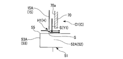
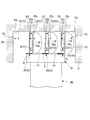
- the steam turbine 1 ⁇ / b> A includes a step portion 52 provided in the tip shroud 51, a seal fin 15 extending from the partition plate outer ring 11 toward the step portion 52, and a downstream side of the seal fin 15. And a partition plate 70 provided to face each other.
- the step portion 52 is provided on the tip shroud 51 that is the tip portion of the rotor blade 50 in the final stage, and has a step surface 53 and protrudes toward the partition plate outer ring 11 side.
- the chip shroud 51 is provided with three step portions 52 (52A to 52C). These three step portions 52 (52A to 52C) are arranged such that the protruding height from the moving blade 50 gradually increases from the upstream side to the downstream side in the axis O direction of the shaft body 30. That is, in the step portion 52 (52A to 52C), three step surfaces 53 (53A to 53C) that form steps are formed facing the upstream side in the axial direction.
- the groove bottom surface 11b in the annular groove 11a of the partition plate outer ring 11 is also formed in a step shape toward the axis O direction so as to correspond to each step portion 52 in the axis O direction. Yes.
- the partition is formed by the seal fin 15A corresponding to the step part 52A located on the upstream side in the axial direction. Therefore, a second cavity C2 is formed between the seal fin 15A and the seal fin 15B and between the tip shroud 51 and the partition plate outer ring 11. Similarly, a third cavity C3 is formed between the seal fin 15B and the seal fin 15C and between the chip shroud 51 and the partition plate outer ring 11.
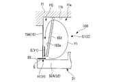
- the partition plate 70 is opposed to the seal fins 15 (in this embodiment, the seal fins 15A and 15B) on the downstream side of the seal fins 15 and in parallel with the seal fins 15 (15A and 15B).
- This is a ring-shaped member that extends radially inward from the groove bottom surface 11 b of the partition plate outer ring 11.
- each cavity C A communication portion 70b is formed to communicate the space on the downstream side of the partition plate 70 in C1, C2) and the steam flow path FC.
- the communication portion 70b may be a plurality of holes that penetrate the partition plate 70 in the direction of the axis O, or may be slits that are spaced apart from each other in the circumferential direction. Any shape may be used as long as it penetrates the partition plate 70 at a position. Further, the partition plate 70 may be provided on the downstream side of each seal fin 15 by being supported on the opposing seal fin 15 by a rib or the like. In this case, the communication portion 70b is formed so as to open in the entire circumferential direction.
- the edge part inside radial direction in this partition plate 70 is located in radial direction outer side rather than seal fin 15 (15A, 15B), and an extension dimension becomes smaller than seal fin 15 (15A, 15B).
- the dimension is at least the extension dimension of the seal fins 15 (15A, 15B).
- the partition plate 70 is steamed in the steam flow path FC along the steam introduction surface (fluid introduction surface) 70a which is a surface facing the upstream side facing the corresponding seal fin 15 (15A, 15B). S is circulated inward in the radial direction, and the steam S is guided to the minute gap H (H1 to H3).
- the steam S flowing into the annular groove 11a first flows into the first cavity C1, collides with the step surface 53A of the step portion 52A, and returns to the upstream side.
- a main vortex Y1 is generated that rotates counterclockwise on the paper surface of FIG. 2A. In this manner, the main vortex Y1 can be reliably generated by providing the step portion 52A.
- the main vortex Y1 and the counter vortex Y2 are formed similarly to the upstream side of the seal fin 15A, and the contraction effect of reducing the flow rate of the leak flow is exhibited.
- the partition plate 70 is provided on the downstream side of each seal fin 15 (15A, 15B), so that the leak flow that has passed through the minute gap H (H1, H2) is radially inward. It is possible to further improve the contraction effect of the leak flow.
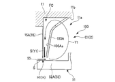
- the partition plate 103 is provided such that the circumferential cross section of the axis O is linearly inclined toward the upstream side from the radially outer side toward the inner side.
- the partition plate 103 is provided so that the steam flow path FC is gradually narrowed in the direction of the axis O toward the radially inner side.
- the partition plate 103 ⁇ / b> A may be provided such that the circumferential section of the axis O is curved. That is, the curve is curved toward the upstream side from the radially outer side to the upstream side, and the circumferential cross section swells to the upstream side.
- the seal fins 15 (15A and 15B) are substantially omitted. It is provided so that it may become parallel. With such a shape, more steam S can be introduced from the main vortex Y1 into the steam flow path FC on the radially outer side, and the flow direction of the steam S in the steam flow path FC on the radially inner side is a direction toward the radial direction.
- the steam S can be circulated along the steam introduction surface 103Aa. Therefore, the contraction effect of the leak flow can be further enhanced.
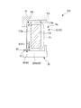
- the block-shaped member 113 has an annular shape and a certain thickness in the direction of the axis O so as to be located just inside the main vortex Y1. Further, the circumferential cross section of the block-shaped member 113 has a substantially rectangular shape. That is, the steam introduction surface 113a is a surface where each block-like member 113 faces the corresponding seal fin 15 (15A, 15B). Further, at the radially outer position, a communication portion 113b that communicates each cavity C (C1, C2) and the steam flow path FC is formed as in the first embodiment and the second embodiment.
- the main vortex Y1 can be circulated along the surface of the block-shaped member 113, and all of the steam S forming the main vortex Y1 can be guided into the steam flow path FC. Therefore, more steam S can be circulated toward the minute gap H (H1, H2), and the contraction effect of the leak flow that has passed through the minute gap H (H1, H2) can be further obtained.
- the block-shaped member 113 may have a perfect quadrilateral circumferential cross section, but preferably has a rounded shape with rounded corners as shown in FIG.
- the surface of the block-shaped member 113B other than the steam introduction surface 113Ba may have a curved shape in the circumferential cross section along the main vortex Y1.
- the block-shaped member 113B does not hinder the flow of the main vortex Y1, the effect of contracting the leak flow can be improved.
- the step portion 52 does not necessarily have to be provided in the tip shroud 51 that is the tip portion of the rotor blade 50 in the final stage. Even in such a case, since the main vortex Y1 is generated by the viscosity of the steam S, the contraction effect of the leak flow by the steam introduction surface 70a (103a, 103Aa, 113Aa, 113Ba) can be obtained. Is possible.
- the groove bottom surface 11 b of the annular groove 11 a of the partition plate outer ring 11 is not formed in a step shape, but may be a step shape as in the first to third embodiments.
- the flow rate reduction of the leak flow between the moving blade 50 and the partition plate outer ring 11 has been described.
- the same method can be applied between the stationary blade 40 and the shaft body 30.
- the step portion 52 (52A to 52C) is formed in the tip shroud 51 that is the tip portion of the moving blade 50, and the seal fin 15 (15A to 15C) is provided in the outer ring 11 of the partition plate.
- the step portion 52 may be formed in the partition plate outer ring 11, and the seal fin 15 may be provided in the chip shroud 51.
- the steam turbine 1A (100, 110) has been described as an example of the rotary machine.
- the steam turbine 1A (100, 110) may be a rotary machine such as a gas turbine or a compressor. It is also possible to apply.
Landscapes
- Engineering & Computer Science (AREA)
- General Engineering & Computer Science (AREA)
- Mechanical Engineering (AREA)
- Turbine Rotor Nozzle Sealing (AREA)
- Sealing Using Fluids, Sealing Without Contact, And Removal Of Oil (AREA)
- Sealing Devices (AREA)
Abstract
Description
本願は、2012年10月18日に、日本に出願された特願2012-230746号に基づき優先権を主張し、その内容をここに援用する。
蒸気タービン1Aは、蒸気Sのエネルギーを回転動力として取り出す外燃機関であって、発電所における発電機等に用いられる。
これら複数の静翼40からなる環状静翼群は、軸方向に間隔をあけて六つ形成されており、蒸気Sの圧力エネルギーを速度エネルギーに変換して、下流側に隣接する動翼50側に案内するように構成されている。
本実施形態では、チップシュラウド51には三つのステップ部52(52A~52C)が設けられている。これら三つのステップ部52(52A~52C)は、軸体30の軸線O方向の上流側から下流側に向かって、動翼50からの突出高さが次第に高くなるように配設されている。即ち、ステップ部52(52A~52C)には、段差を形成する三つの段差面53(53A~53C)が、軸方向上流側を向いて形成されている。
ここで、本実施形態では、段差面53Bはシールフィン15Aの下流側に、段差面53Cはシールフィン15Bの下流側に位置しており、段差面53Aはシールフィン15Aの上流側に位置している。そして、段差面53Aによって後述するキャビティC1内の径方向外側に、段差面53Bによって後述するキャビティC2内の径方向外側に、段差面53Cによって後述するキャビティC3内の径方向外側に蒸気Sが導かれるように構成されている。
キャビティC(C1~C3)は、各ステップ部52(52A~52C)に対応したシールフィン15(15A~15C)と、このシールフィン15(15A~15C)に対して、軸線O方向の上流側で対向する隔壁との間に形成されている。
同様に、シールフィン15Bとシールフィン15Cとの間で、さらにチップシュラウド51と仕切板外輪11との間に、第3のキャビティC3が形成されている。
仕切り板70は、各シールフィン15の下流側で、各シールフィン15(本実施形態ではシールフィン15Aとシールフィン15B)に対向するように、そして各シールフィン15(15A、15B)に平行に、仕切板外輪11の溝底面11bから径方向内側に延出して設けられた環状をなす部材である。さらに、この仕切り板70においては、対応するシールフィン15(15A、15B)との間で蒸気Sを導入する蒸気流路FCを画成するとともに、この径方向外側の位置では、各キャビティC(C1、C2)における仕切り板70の下流側の空間と蒸気流路FCとを連通する連通部70bが形成されている。
また、仕切り板70は、対向するシールフィン15にリブ等によって支持されることで、各シールフィン15の下流側に設けられていてもよい。この場合の連通部70bは、周方向全域に開口して形成される。
よって、図2Bの破線に示す流れから実線で示す流れとなるように、微小隙間H(H1、H2)を通過したリーク流を径方向内側に向かって押し付けることができる。換言すると、微小隙間H(H1、H2)のクリアランスを擬似的に小さくすることとなる。
次に、本発明の第二実施形態に係る蒸気タービン100について説明する。
なお、第一実施形態と共通の構成要素には同一の符号を付して詳細説明を省略する。
本実施形態では、仕切り板103の形状が第一実施形態とは異なっている。
次に、本発明の第三実施形態に係る蒸気タービン110について説明する。
なお、第一実施形態及び第二実施形態と共通の構成要素には同一の符号を付して詳細説明を省略する。
本実施形態では、蒸気導入面110aを形成する部材が仕切り板70(103、103A)に代えて、ブロック状部材113である点で第一実施形態及び第二実施形態とは異なっている。
例えば、図6Aに示すように、ブロック状部材113Aにおける蒸気導入面113Aaが径方向外側から内側に向かって上流側に傾斜するように形成されていてもよい。この場合には、第二実施形態で説明したように、リーク流の縮流効果をさらに向上可能である。なお、ブロック状部材113Aは、図6Aに示すように角部がR形状となって丸みを持った形状であることが好ましい。
また、図6Bに示すように、ブロック状部材113Bにおける蒸気導入面113Ba以外の表面が、主渦Y1に沿うように周方向断面で曲線状をなしていてもよい。この場合には、ブロック状部材113Bが主渦Y1の流れを妨げることがないので、リーク流の縮流効果を向上できる。
例えば、図7に示すように、最終段の動翼50の先端部となるチップシュラウド51には、ステップ部52は必ずしも設けられていなくともよい。このような場合であっても、主渦Y1は蒸気Sの粘性によって生成されるものであるため、蒸気導入面70a(103a、103Aa、113Aa、113Ba)によるリーク流の縮流効果を得ることが可能である。なお、図7では仕切板外輪11の環状溝11aにおける溝底面11bについてもステップ状に形成されていないが、第一実施形態から第三実施形態と同様にステップ状であってもよい。
10 ケーシング
11 仕切板外輪(ステータ)
11a 環状溝
11b 溝底面
20 調整弁
21 調整弁室
22 弁体
23 弁座
30 軸体
31 軸本体
32 ディスク
40 静翼
41 ハブシュラウド
50 動翼
51 チップシュラウド(ロータ)
52 ステップ部
53 段差面
54 内壁面
55 端縁部
60 軸受部
61 ジャーナル軸受装置
62 スラスト軸受装置
70 仕切り板
70a 蒸気導入面(流体導入面)
70b 連通部
FC 蒸気流路(空間)
S 蒸気
O 軸線
Y1 主渦
Y2 カウンタ渦
H 微小隙間
C キャビティ
100 蒸気タービン
103 仕切り板
103a 蒸気導入面
103A 仕切り板
110 蒸気タービン
113 ブロック状部材
113a 蒸気導入面(流体導入面)
113b 連通部
113A ブロック状部材
113Aa 蒸気導入面(流体導入面)
113B ブロック状部材
113Ba 蒸気導入面(流体導入面)
Claims (8)
- 軸線に沿って流体が流通する回転機械において、
前記軸線を中心に延びるロータと、
前記ロータの径方向に対向して、前記軸線回りに該ロータに対して相対回転可能に設けられたステータと、
前記ロータと前記ステータとのうちの一方から他方に延出して、該他方との間に隙間を形成するシールフィンと、
前記シールフィンの下流側に形成されて前記隙間を通過するリーク流に基づく渦が生成されるキャビティ内に前記シールフィンに対向するように設けられ、前記渦に基づく流れを前記隙間に向かって導く流体導入面と、
を備える回転機械。 - 前記流体導入面は、前記一方側から前記他方側に向かうに従って、下流側から上流側に向かうように傾斜して設けられている請求項1に記載の回転機械。
- 前記流体導入面は、前記シールフィンに沿って設けられた仕切り板の上流側を向く表面であり、
前記仕切り板における前記一方側には、該仕切り板と前記シールフィンとの間に画成される空間と、前記キャビティにおける前記仕切り板の下流側の空間とを連通する連通部が形成されている請求項1に記載の回転機械。 - 前記流体導入面は、前記シールフィンに沿って設けられた仕切り板の上流側を向く表面であり、
前記仕切り板における前記一方側には、該仕切り板と前記シールフィンとの間に画成される空間と、前記キャビティにおける前記仕切り板の下流側の空間とを連通する連通部が形成されている請求項2に記載の回転機械。 - 前記ロータと前記ステータとのうちの前記他方において前記シールフィンの下流側となる位置で、前記隙間に対向する位置に設けられて、上流側を向いて前記リーク流を前記キャビティ内における前記一方側に導く段差面をさらに備える請求項1に記載の回転機械。
- 前記ロータと前記ステータとのうちの前記他方において前記シールフィンの下流側となる位置で、前記隙間に対向する位置に設けられて、上流側を向いて前記リーク流を前記キャビティ内における前記一方側に導く段差面をさらに備える請求項2に記載の回転機械。
- 前記ロータと前記ステータとのうちの前記他方において前記シールフィンの下流側となる位置で、前記隙間に対向する位置に設けられて、上流側を向いて前記リーク流を前記キャビティ内における前記一方側に導く段差面をさらに備える請求項3に記載の回転機械。
- 前記ロータと前記ステータとのうちの前記他方において前記シールフィンの下流側となる位置で、前記隙間に対向する位置に設けられて、上流側を向いて前記リーク流を前記キャビティ内における前記一方側に導く段差面をさらに備える請求項4に記載の回転機械。
Priority Applications (4)
| Application Number | Priority Date | Filing Date | Title |
|---|---|---|---|
| US14/434,896 US9896952B2 (en) | 2012-10-18 | 2013-10-17 | Rotating machine |
| EP13847399.6A EP2894377B1 (en) | 2012-10-18 | 2013-10-17 | Turbo-engine |
| KR1020157009615A KR101700055B1 (ko) | 2012-10-18 | 2013-10-17 | 회전 기계 |
| CN201380053935.XA CN104736906B (zh) | 2012-10-18 | 2013-10-17 | 旋转机械 |
Applications Claiming Priority (2)
| Application Number | Priority Date | Filing Date | Title |
|---|---|---|---|
| JP2012-230746 | 2012-10-18 | ||
| JP2012230746A JP5936515B2 (ja) | 2012-10-18 | 2012-10-18 | 回転機械 |
Publications (1)
| Publication Number | Publication Date |
|---|---|
| WO2014061736A1 true WO2014061736A1 (ja) | 2014-04-24 |
Family
ID=50488296
Family Applications (1)
| Application Number | Title | Priority Date | Filing Date |
|---|---|---|---|
| PCT/JP2013/078181 WO2014061736A1 (ja) | 2012-10-18 | 2013-10-17 | 回転機械 |
Country Status (6)
| Country | Link |
|---|---|
| US (1) | US9896952B2 (ja) |
| EP (1) | EP2894377B1 (ja) |
| JP (1) | JP5936515B2 (ja) |
| KR (1) | KR101700055B1 (ja) |
| CN (1) | CN104736906B (ja) |
| WO (1) | WO2014061736A1 (ja) |
Families Citing this family (5)
| Publication number | Priority date | Publication date | Assignee | Title |
|---|---|---|---|---|
| KR102172175B1 (ko) * | 2014-05-28 | 2020-11-02 | 한국전력공사 | 이물질 포집 기능을 갖는 터빈 |
| JP6510915B2 (ja) * | 2015-07-03 | 2019-05-08 | 株式会社神戸製鋼所 | ラビリンスシール |
| JP2017145813A (ja) * | 2016-02-19 | 2017-08-24 | 三菱日立パワーシステムズ株式会社 | 回転機械 |
| JP6675262B2 (ja) | 2016-05-09 | 2020-04-01 | 三菱日立パワーシステムズ株式会社 | シールセグメント及び回転機械 |
| JP6783257B2 (ja) * | 2018-01-31 | 2020-11-11 | 三菱重工業株式会社 | 軸流回転機械 |
Citations (4)
| Publication number | Priority date | Publication date | Assignee | Title |
|---|---|---|---|---|
| DE1159227B (de) * | 1961-04-06 | 1963-12-12 | Bbc Brown Boveri & Cie | Labyrinthstopfbuechse |
| JP2002228014A (ja) * | 2001-02-05 | 2002-08-14 | Mitsubishi Heavy Ind Ltd | ラビリンスシール |
| JP2011080452A (ja) | 2009-10-09 | 2011-04-21 | Mitsubishi Heavy Ind Ltd | タービン |
| JP2011208602A (ja) * | 2010-03-30 | 2011-10-20 | Mitsubishi Heavy Ind Ltd | タービン |
Family Cites Families (12)
| Publication number | Priority date | Publication date | Assignee | Title |
|---|---|---|---|---|
| IT1063035B (it) | 1975-05-09 | 1985-02-11 | Maschf Augsburg Nuernberg Ag | Apparato per la realizzazione del procedimento per elevare il limite dinamico di potenza di turbine a vapore od a gas o di compressori |
| JPH0520931Y2 (ja) * | 1986-10-02 | 1993-05-28 | ||
| JPH0640377Y2 (ja) * | 1989-03-30 | 1994-10-19 | 日本精工株式会社 | 磁性流体シール装置 |
| US5599026A (en) | 1995-09-06 | 1997-02-04 | Innovative Technology, L.L.C. | Turbine seal with sealing strip and rubbing strip |
| JPH09324655A (ja) * | 1996-06-07 | 1997-12-16 | Hitachi Ltd | ガス膨張タービン |
| JP2006291967A (ja) | 2006-05-29 | 2006-10-26 | Toshiba Corp | 軸流タービン |
| US7445213B1 (en) * | 2006-06-14 | 2008-11-04 | Florida Turbine Technologies, Inc. | Stepped labyrinth seal |
| US7708520B2 (en) * | 2006-11-29 | 2010-05-04 | United Technologies Corporation | Gas turbine engine with concave pocket with knife edge seal |
| US8206082B2 (en) * | 2009-04-29 | 2012-06-26 | General Electric Company | Packing seal rotor lands |
| JP5411569B2 (ja) * | 2009-05-01 | 2014-02-12 | 株式会社日立製作所 | シール構造とその制御方法 |
| JP5725848B2 (ja) * | 2010-12-27 | 2015-05-27 | 三菱日立パワーシステムズ株式会社 | タービン |
| WO2014138623A1 (en) * | 2013-03-08 | 2014-09-12 | Rolls-Royce Corporation | Slotted labyrinth seal |
-
2012
- 2012-10-18 JP JP2012230746A patent/JP5936515B2/ja not_active Expired - Fee Related
-
2013
- 2013-10-17 KR KR1020157009615A patent/KR101700055B1/ko active IP Right Grant
- 2013-10-17 WO PCT/JP2013/078181 patent/WO2014061736A1/ja active Application Filing
- 2013-10-17 CN CN201380053935.XA patent/CN104736906B/zh not_active Expired - Fee Related
- 2013-10-17 US US14/434,896 patent/US9896952B2/en not_active Expired - Fee Related
- 2013-10-17 EP EP13847399.6A patent/EP2894377B1/en not_active Not-in-force
Patent Citations (4)
| Publication number | Priority date | Publication date | Assignee | Title |
|---|---|---|---|---|
| DE1159227B (de) * | 1961-04-06 | 1963-12-12 | Bbc Brown Boveri & Cie | Labyrinthstopfbuechse |
| JP2002228014A (ja) * | 2001-02-05 | 2002-08-14 | Mitsubishi Heavy Ind Ltd | ラビリンスシール |
| JP2011080452A (ja) | 2009-10-09 | 2011-04-21 | Mitsubishi Heavy Ind Ltd | タービン |
| JP2011208602A (ja) * | 2010-03-30 | 2011-10-20 | Mitsubishi Heavy Ind Ltd | タービン |
Non-Patent Citations (1)
| Title |
|---|
| See also references of EP2894377A4 |
Also Published As
| Publication number | Publication date |
|---|---|
| EP2894377A1 (en) | 2015-07-15 |
| KR101700055B1 (ko) | 2017-01-26 |
| US9896952B2 (en) | 2018-02-20 |
| CN104736906B (zh) | 2016-10-05 |
| JP5936515B2 (ja) | 2016-06-22 |
| JP2014081050A (ja) | 2014-05-08 |
| EP2894377B1 (en) | 2016-12-28 |
| EP2894377A4 (en) | 2015-11-18 |
| CN104736906A (zh) | 2015-06-24 |
| US20150300190A1 (en) | 2015-10-22 |
| KR20150055051A (ko) | 2015-05-20 |
Similar Documents
| Publication | Publication Date | Title |
|---|---|---|
| KR101496530B1 (ko) | 터빈 | |
| KR101279191B1 (ko) | 터빈 | |
| JP5709447B2 (ja) | タービン | |
| US9353640B2 (en) | Turbine | |
| US10557363B2 (en) | Sealing structure and rotary machine | |
| WO2014061736A1 (ja) | 回転機械 | |
| JP5725848B2 (ja) | タービン | |
| US20140314579A1 (en) | Turbine | |
| JP5518022B2 (ja) | タービン | |
| KR102290579B1 (ko) | 동익, 로터 유닛 및 회전 기계 | |
| JP2011012631A (ja) | タービン | |
| JP5412571B2 (ja) | タービン | |
| JP2010275957A (ja) | タービン |
Legal Events
| Date | Code | Title | Description |
|---|---|---|---|
| 121 | Ep: the epo has been informed by wipo that ep was designated in this application |
Ref document number: 13847399 Country of ref document: EP Kind code of ref document: A1 |
|
| REEP | Request for entry into the european phase |
Ref document number: 2013847399 Country of ref document: EP |
|
| WWE | Wipo information: entry into national phase |
Ref document number: 2013847399 Country of ref document: EP |
|
| WWE | Wipo information: entry into national phase |
Ref document number: 14434896 Country of ref document: US |
|
| ENP | Entry into the national phase |
Ref document number: 20157009615 Country of ref document: KR Kind code of ref document: A |
|
| NENP | Non-entry into the national phase |
Ref country code: DE |