WO2014057599A1 - 電力融通システム、電力融通方法及びプログラムを格納した非一時的なコンピュータ可読媒体 - Google Patents
電力融通システム、電力融通方法及びプログラムを格納した非一時的なコンピュータ可読媒体 Download PDFInfo
- Publication number
- WO2014057599A1 WO2014057599A1 PCT/JP2013/004845 JP2013004845W WO2014057599A1 WO 2014057599 A1 WO2014057599 A1 WO 2014057599A1 JP 2013004845 W JP2013004845 W JP 2013004845W WO 2014057599 A1 WO2014057599 A1 WO 2014057599A1
- Authority
- WO
- WIPO (PCT)
- Prior art keywords
- power
- management device
- consumer
- consumer management
- condition
- Prior art date
- Legal status (The legal status is an assumption and is not a legal conclusion. Google has not performed a legal analysis and makes no representation as to the accuracy of the status listed.)
- Ceased
Links
Images


Classifications
-
- H—ELECTRICITY
- H02—GENERATION; CONVERSION OR DISTRIBUTION OF ELECTRIC POWER
- H02J—ELECTRIC POWER NETWORKS; CIRCUIT ARRANGEMENTS OR SYSTEMS FOR SUPPLYING OR DISTRIBUTING ELECTRIC POWER; SYSTEMS FOR STORING ELECTRIC ENERGY
- H02J3/00—Circuit arrangements for AC mains or AC distribution networks
- H02J3/38—Arrangements for feeding a single network from two or more generators or sources in parallel; Arrangements for feeding already energised networks from additional generators or sources in parallel
- H02J3/46—Controlling the sharing of generated power between the generators, sources or networks
-
- G—PHYSICS
- G05—CONTROLLING; REGULATING
- G05B—CONTROL OR REGULATING SYSTEMS IN GENERAL; FUNCTIONAL ELEMENTS OF SUCH SYSTEMS; MONITORING OR TESTING ARRANGEMENTS FOR SUCH SYSTEMS OR ELEMENTS
- G05B11/00—Automatic controllers
- G05B11/01—Automatic controllers electric
- G05B11/012—Automatic controllers electric details of the transmission means
-
- G—PHYSICS
- G05—CONTROLLING; REGULATING
- G05B—CONTROL OR REGULATING SYSTEMS IN GENERAL; FUNCTIONAL ELEMENTS OF SUCH SYSTEMS; MONITORING OR TESTING ARRANGEMENTS FOR SUCH SYSTEMS OR ELEMENTS
- G05B15/00—Systems controlled by a computer
- G05B15/02—Systems controlled by a computer electric
Definitions
- the present invention relates to a power interchange system, a power interchange method, and a non-transitory computer readable medium storing a program, and relates to, for example, a technique for performing rapid and flexible power interchange.
- a system has been proposed for a supplier having a distributed power generation facility to allow power to be supplied to a consumer who needs power.
- Patent Document 1 in an electric power system in which an electric power supplier site and an electric power consumer site are connected, electric power is interchanged from the electric power supplier site to the electric power consumer site in an emergency, and at that time, the electric power business It is described that an operator (electric power company) controls the operation of power supply equipment so that the principle of the same amount in the electric power system is satisfied at a small cost.
- Patent Document 1 in a configuration in which a customer and a supplier perform power interchange through an electric power system managed by an electric power company, it is necessary to adjust the supply and demand balance in the electric power system as described above. The flexibility of power interchange is low, and quick power interchange in an emergency is difficult.
- the supply of electricity and the supply and demand consideration are generally paid in money.
- the consideration of the supply of power that the supplier has made to other consumers is different from that in an emergency. It has been difficult to make flexible power interchange contracts that can be obtained by receiving power from other suppliers.
- the present invention has been made to solve such a problem, and is a non-transitory computer storing a power interchange system, a power interchange method, and a program capable of performing quick and flexible power interchange.
- An object is to provide a readable medium.
- the power interchange system includes a plurality of consumer management devices constituting an autonomously controlled grid, and a power management device that performs power interchange between the consumer management devices, and the power management device Associates at least one of the first condition, which is a condition for receiving power with each consumer management device, and the second condition, which is a condition for supplying power, with each consumer management device.
- the information control means detects that the first consumer management device has fulfilled the first condition, the information control means supplies power to the second consumer management device that satisfies the second condition.
- the power control means requesting the supply
- the power supplied from the second consumer management device is supplied to the first consumer management device, and the consumer management device consumes the distributed power source that generates power and the power.
- At least one of the loads, and a control unit that controls the distributed power source, and the control unit supplies power to the power management apparatus in response to a request from the information control unit; It controls power reception from the power control means.
- the information control means of the power management apparatus fulfills the first condition, which is a condition that the first consumer management apparatus receives power from the first consumer management apparatus. Detecting the above, requesting the second consumer management device that satisfies the second condition, which is a condition for the second consumer management device to supply power, to supply power, and
- the power control means of the power management apparatus includes a step of receiving the power from the second consumer management apparatus and supplying the power to the first consumer management apparatus.
- the non-transitory computer readable medium storing the program according to the present invention is a non-transitory computer readable medium storing a program for causing a computer to execute the above method.
- a non-transitory computer-readable medium storing a power accommodation system, a power accommodation method, and a program capable of performing quick and flexible power accommodation.
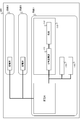
- FIG. 1 is a diagram showing a configuration of a power accommodation system 100 according to a first exemplary embodiment.
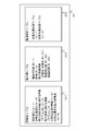
- 3 is a diagram illustrating a configuration of a management information storage unit 121.
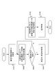
- FIG. It is a figure which shows the process of the power interchange system 100 concerning Embodiment 1.
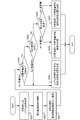
- FIG. It is a figure which shows the conclusion flow of the electric power interchange contract in Embodiment 2.
- FIG. It is a figure which shows the process of the electric power interchange system 100 concerning Embodiment 2.
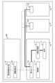
- FIG. It is a figure which shows the structure of the electric power interchange system 200 concerning Embodiment 3.
- FIG. It is a figure which shows the structure in the case of performing power interchange between different systems without using the power router 230. It is a figure which shows the structure of the electric power interchange system concerning other embodiment.
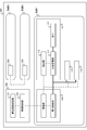
- FIG. 1 is a block diagram showing a configuration of a power interchange system 100 according to the first embodiment.
- the power interchange system 100 includes a plurality of consumer management devices 110 and a power management device 120.
- the power management device 120 is typically connected to a power system (main system) such as an electric power company at a connection point, and supplies power from the main system to each consumer management device 110. It is also possible to control power interchange within 100 independently from the backbone system.
- the power interchange system 100 is, for example, a microgrid.
- a microgrid a power system (grid) that has power generation facilities using renewable energy, etc., and is autonomously distributed and controlled by each consumer management device 110, independently of power supply from a main system managed by an electric power company Are arranged, and the power of a plurality of consumers in the grid is managed in the grid.
- the consumer management device 110 is a device that manages the receipt of power by consumers in the microgrid, and stable power control is performed by each customer management device 110 performing autonomous operation.
- a plurality of customer management devices 110 may exist in the same grid, and may perform power interchange within the same grid, or may perform power interchange between different grids.
- Each of the consumer management apparatuses 110 includes at least one of a distributed power source 111 and a load 112 and a control unit 113.
- Each consumer management device 110 may have a plurality of distributed power sources 111 and loads 112.
- the distributed power source 111 is various facilities and devices that generate power.
- the distributed power source 111 includes a gas engine / gas turbine generator, a solar power generator, a wind power generator, a biomass power generator, a fuel cell, a storage battery (during discharging), and the like.
- the distributed power source 111 is connected to the load 112 and the power control unit 123 of the power management apparatus 120 so as to be able to transmit and receive power.
- the load 112 is various facilities and devices that consume power.
- a storage battery (during charging) is also included in the load 112.
- the load 112 is connected to the distributed power source 111 and the power control unit 123 of the power management apparatus 120 so as to be able to transmit and receive power.
- the control unit 113 controls the output of the distributed power source 111 in accordance with an instruction from the power control unit 123 of the power management apparatus 120.
- the control unit 113 is typically a computer having a storage unit that stores a program, a processor that performs processing according to the program, and an input / output unit that performs information communication with the power control unit 123 and the distributed power source 111. is there.
- the control unit 113 is communicably connected to the distributed power source 111, the load 112, and the power control unit 123 of the power management apparatus 120.
- the power management apparatus 120 includes a management information storage unit 121, an information control unit 122, and a power control unit 123.
- the management information storage unit 121 holds profiles (attribute values such as power generation amount and set values such as power interchange conditions) of each consumer management device 110. Typically, it is a database that is logically constructed on the storage unit. Detailed contents of the management information storage unit 121 will be described later.
- the information control unit 122 detects the fulfillment of a predetermined condition based on the function of setting the profile of each consumer management device 110 in the management information storage unit 121 and the profile, and controls the predetermined consumer management device 110. A function of instructing the power control unit 123 to supply the unit 113 with a predetermined amount of power.
- the power control unit 123 responds to a function of supplying power received from the distributed power source 111 or the backbone of the consumer management device 110 to the load 112 of the other consumer management device 110 and an instruction from the information control unit 122. It has a function of instructing the control unit 113 of a predetermined consumer management device 110 to supply a predetermined amount of power.
- the information control unit 122 and the power control unit 123 typically input and output information communication with a storage unit that stores a program and the like, a processor that performs processing according to the program, and the control unit 113 of the consumer management apparatus 110.
- a computer having a unit.
- management information stored in the management information storage unit will be described with reference to FIG.
- the management information storage unit 121 has three tables: a consumer table 1211, a power network table 1212, and an accommodation control table 1213.
- the consumer table 1211 is a table that holds a profile of each consumer management device 110. When a new consumer management device 110 joins the power interchange system 100, a new entry is created in the consumer table 1211.
- the consumer table 1211 includes the following entries.
- the contractor ID (A-1) is an identifier (ID) for identifying each consumer management device 110.
- the distributed power source ID (A-2) is an ID for identifying the distributed power source 111 included in the consumer management apparatus 110. When the contractor has a plurality of distributed power sources 111, a plurality of distributed power source IDs corresponding to the distributed power sources 111 are associated with the contractor ID.
- Information (option fee) (A-3) relating to the value of power supply is information indicating what the consumer management apparatus 110 should supply to the power management apparatus 120 as a price for the contract received power, which will be described later, and supply conditions. .
- Information (option) (A-4) relating to power reception is information indicating the amount of power (contract received power amount) that can be received from the power management device 120 by the consumer management device 110 and the receiving conditions.
- the type (A-5) of the distributed power source is information indicating specifications of the distributed power source 111 (for example, whether it is natural energy, inverter conversion efficiency, etc.).
- the maximum power generation amount (A-6) of the distributed power source is information indicating the maximum power amount that can be generated by the distributed power source 111.
- the concept of options and option fees in the information on power receipt (option) (A-4) and information on consideration for power receipt (option fee) (A-3) It is almost synonymous with concept. That is, the option refers to a right that the consumer management device 110 receives a predetermined amount of power from the power management device 120 when a predetermined condition is fulfilled in the future.
- the option fee refers to the price of the right that the consumer management device 110 delivers to the power management device 120.
- the power network table 1212 is a table that holds information on the power network related to the power interchange system 100, and includes the following entries.
- the power supply state (B-1) indicates whether each of the distributed power supply 111 and the main power generation apparatus is operating, or whether power can be received from these (currently operating, Information indicating the status of the switch).
- the distance (B-2) is information indicating a power transmission distance from one consumer management device 110 to another consumer management device 110.
- the power interchange information (B-31 to B-33) is information that is set when power interchange is executed from one consumer management device 110 to another consumer management device 110. B-31), accommodation power amount (B-32), and accommodation period (B-33).
- the accommodation control table 1213 is a table that holds information for determining a power transmission source and a power transmission destination at the time of power accommodation.
- the accommodation control table 1213 includes a power transmission source priority table (C-1) and a power transmission destination priority table (C-2).
- the power transmission source priority table (C-1) is a table in which the contractor ID of the consumer management apparatus 110 as a power transmission source candidate is recorded in advance together with the priority.
- the power management system 120 determines a power transmission source based on the priority defined in the power transmission source priority table (C-1).
- the power transmission destination priority table (C-2) is a table in which the contractor ID of the consumer management apparatus 110 as a power transmission destination candidate is recorded in advance together with the priority.
- the power management system 120 determines the power transmission destination based on the priority defined in the power transmission destination priority table (C-2).
- the power transmission destination needs to be superior or inferior, for example, when the total amount of power supplied from the power transmission source is lower than the total amount of power to be supplied to the power transmission destination, it is supplied from a plurality of power transmission sources. For example, there is a difference in power stability.
- the accommodation control table 1213 may appropriately hold other parameters that can be used to determine the power transmission source and the power transmission destination.
- the priorities of the power transmission source priority table (C-1) and the power transmission destination priority table (C-2) may be determined based on various factors. For example, a consumer who is given a high priority in the power transmission source priority table (C-1) may be given a high priority in the power transmission destination priority table (C-2).
- priority of the power transmission destination priority table (C-2) may be set according to the contents of the information (option fee) (A-3) related to the power supply consideration, for example, the amount of the consideration.
- the contents of power accommodation arrangement (power accommodation contract) in the power accommodation system 100 are registered in the management information storage unit 121 in advance.
- the contents of the power interchange contract to be registered in advance in the management information storage unit 121 are shown below.
- the consumer who operates each consumer management apparatus 110 negotiates in advance information (option) related to power reception and information (option fee) related to consideration for power reception.
- the consumer sets the amount of power (contracted received power amount) that can be received from the power management device 120 by the consumer management device 110 and the receiving conditions as information (option) related to power reception.
- information (option fee) related to the price for receiving power what is to be supplied by the consumer management apparatus 110 to the power management apparatus 120 as the price for the contract received power amount and supply conditions are set.
- the contract received power amount of information (option) related to power reception is the amount of power that the consumer management device 110 receives from the power management device 120 when a receiving condition described later is fulfilled.
- the consumer can set, for example, the maximum amount of power required to operate the load 112 of the consumer management device 110 as the contract received power amount. As a result, for example, even when the power generation amount of the distributed power source 111 of the consumer management device 110 is lost due to trouble such as an accident or a power failure, the power necessary for operating the load 112 can be procured.
- the condition for receiving information (option) regarding power reception is a condition to be satisfied in order for the consumer management device 110 to receive the contract received power amount from the power management device 120.
- the consumer can set an event such as a stop of the distributed power supply 111 of the consumer management apparatus 110 as the receiving condition.
- the power management apparatus 120 can detect the stop of the distributed power supply 111 by regularly performing life and death management of the distributed power supply 111.
- the receiving conditions include the occurrence of a power outage in the customer management device 110, the occurrence of an abnormality in the backbone system, the occurrence of a request for charging the storage battery, and the scheduled execution period of an event that requires a large amount of power Any event that the power management apparatus 120 can detect, such as the arrival of
- What is to be supplied as consideration for information related to power receipt (option fee) is transferred to the power management device 120 by the consumer management device 110 as consideration for receiving the contract received power amount when the receipt conditions are met.
- the consumer can set an arrangement in which the consumer management device 100 supplies a predetermined amount of power (contracted power supply amount) to the power management device 120.
- the consumer management device 100 has an obligation to supply the contracted power supply amount to the power management device 120 when a supply condition described later is satisfied. Therefore, the consumer management device 110 needs to be prepared so that the supply of the contracted power supply can be started immediately when the supply condition is satisfied in a normal time when the supply condition is not satisfied.
- what should be supplied as consideration may be payment of money from the consumer to the operator of the power management apparatus 120.
- the consumer management device 110 does not need to make any special preparations during normal times when supply conditions are not met.
- the supply condition of the information (option fee) related to the consideration for receiving power is a condition that the consumer management device 110 should supply the consideration to the power management device 120.
- generation of a power supply request from the power management apparatus 120 to the consumer management apparatus 110 can be set as a supply condition.
- the power management device 120 detects the fulfillment of the receiving condition for any of the consumer management devices 110 in the power interchange system 100, and when the necessity for power interchange in the power interchange system 100 occurs, A power supply request may be issued to the consumer management device 110.
- the power management apparatus 120 performs the processing of S102 to S103 for each consumer management apparatus 110 included in the power interchange system 100. Note that S102 to S103 are normal processing in which none of the consumer management apparatuses 110 fulfills the receiving condition.
- the information control unit 122 of the power management device 120 controls the control unit 112 of the consumer management device 110, and if the supply condition of the information (option fee) related to the consideration of power reception is fulfilled, what should be supplied as consideration
- the consumer management apparatus 110 is prepared so that it can be supplied immediately (S102).
- the control unit 112 performs such preparation by adjusting the output of the distributed power source 111 and the load 112, for example.
- the processing in step S102 is not necessary.
- the information control unit 122 periodically confirms whether the consumer management device 110 has fulfilled the condition for receiving information (option) related to power reception (S103).
- the power management device 120 fulfills the receiving condition, that is, when it becomes necessary for the power management device 120 to supply power to the consumer management device 110 based on the power interchange contract, the power management device 120 The following processes of S104 to S106 are performed.
- the information control unit 122 of the power management device 120 determines one or more other customer management devices 110 (power transmission sources) that should supply power to the consumer management device 110 (power transmission destination) that fulfills the receiving condition. (S104). For example, the information control unit 122 refers to the priority table (C-1) of the accommodation control table 1213, and determines the consumer management device 110 with the contractor ID having a high priority set as the power transmission source. Can do. In addition, the information control unit 122 relates to information (option fee) (A-3) regarding the value of power reception associated with the contractor ID of the power transmission source, and about power reception associated with the contractor ID of the power transmission destination.
- the subordinate priority is defined in the priority table (C-1).
- the customer management devices 110 with other contractor IDs may be additionally allocated sequentially as a power transmission source for the insufficient amount of power.
- the power transmission source may be determined based on other arbitrary parameters, for example, the power transmission distance (B-2).
- the information control unit 122 of the power management apparatus 120 instructs the control unit 112 of the consumer management apparatus 110 determined as the power transmission source to supply the allocated power amount (S105).
- the upper limit of the amount of power allocated to each power transmission source is the contract supply power amount of each power transmission source.
- the power transmission source control unit 112 secures the allocated power amount by adjusting the output of the distributed power source 111 and the load 112 and transmits power to the power control unit 123 of the power management device 120. To do.
- the power control unit 123 of the power management apparatus 120 transmits the power supplied from the power transmission source to the consumer management apparatus 110 that is the power transmission destination (S106).
- the power supply based on the power interchange contract with the power transmission destination is continued until the receiving condition of the power transmission destination is not satisfied.
- the stop of the distributed power source 111 is a receiving condition
- the recovery of the distributed power source 111 can be continued until it is detected by life / death confirmation.
- the event can be continued until the period for the event ends.
- the power management system 120 can select the power transmission destination based on the priority defined in the power transmission destination priority table (C-2) when it is necessary to give priority to the power transmission destination. For example, when the total amount of power supplied from the transmission source is lower than the total amount of power to be supplied to the transmission destination, the power management system 120 has a high priority defined in the transmission destination priority table (C-2). The amount of power transmission can be preferentially allocated to the consumer. In addition, when there is a difference in the stability of power supplied from a plurality of power transmission sources, the power management system 120 gives priority to consumers with high priority defined in the power transmission destination priority table (C-2). A highly stable power transmission source can be assigned. The stability of the supplied power can be determined based on, for example, the type of distributed power supply (A-5).
- the power management apparatus 120 controls the power interchange from other consumer management apparatuses 110 completely independently of the backbone system in accordance with the demand of the consumer management apparatus 110. As a result, it is not necessary to adjust the balance between supply and demand in the backbone system, and it is possible to realize rapid power interchange with a high degree of freedom.
- the contents of the power interchange contract are managed by the management information storage unit 121 independent of the backbone system, and the information control unit 122 performs the above control with reference to the management information storage unit 121. Thereby, it is not necessary to conclude a predetermined contract with the electric power company in advance, and a high degree of freedom and quick power interchange can be realized.
- the management information storage unit 121 can manage various patterns of power interchange contracts, and the information control unit 122 refers to the management information storage unit 121 and uses the various information communication technologies to control the above control. To implement. Thereby, a flexible electric power interchange contract is realizable.
- a consumer who wants to participate in the power interchange system 100 makes a system use application to the operator of the power management apparatus 120 (S201). At this time, the consumer presents the distributed power source type (A-5) and the maximum power generation amount (A-6) of the distributed power source to the operator of the power management apparatus 120. If the consumer does not have a distributed power source, this is indicated.
- a power interchange contract is established (S202).
- the operator of the power management apparatus 120 assigns the contractor ID (A-1) to the consumer.
- a distributed power supply ID (A-2) is assigned to the distributed power supply included in the consumer management apparatus 110 operated by the consumer.
- the information related to A-2 to A-6 is registered in the consumer table 1211 of the management information storage unit 121 in association with the contractor ID (A-1) (S203).
- a consumer management device 110 of a consumer who intends to participate in the power interchange system 100 is connected to the power management device 120 so that power transmission / reception and communication are possible.
- the power management apparatus 120 can monitor the distributed power supply 111 and the load 112 of the consumer management apparatus 110 and perform control via the control unit 113.
- the information control unit 122 of the power management apparatus 120 calculates the distance (B-2) from the newly joined consumer management apparatus 110 to another consumer management apparatus 110 and registers it in the power network table 1212. Further, the information control unit 122 periodically monitors the power supply state (B-1) of the distributed power supply 111 and registers it in the power network table 1212.
- the contents of information (option fee) (A-3) regarding consideration for power reception (A-3) and information (option) (A-4) regarding power reception in the power interchange contract are determined by the following flow.
- the option fee is paid for the system usage fee. If the customer pays the specified system usage fee to the operator of the power management apparatus 120, the payment of the fee (supplied as consideration) is made as information (option fee) (A-3) on the consideration for receiving electricity.
- Information to be paid) (payment conditions) is entered (S209).
- the option fee is paid for the system usage fee. If the customer pays the specified system usage fee to the operator of the power management apparatus 120, the payment of the fee (supplied as consideration) is made as information (option fee) (A-3) on the consideration for receiving electricity. Information to be paid) (payment conditions) is entered (S209).
- the option fee is the contracted power supply amount according to the power supply request. It is preferable to supply the content.
- the information (option fee) (A-3) related to the consideration for power supply the contracted power supply amount (what should be supplied as consideration) and the notification (supply condition) of the power supply request are described (S209).
- the option is preferably reception of the contract received power amount from the power management apparatus 120 in the consumer management apparatus 110.
- the contract received power amount and the receiving conditions are described as information (option) (A-4) regarding the power receiving (S207).
- the receiving condition can be arbitrarily executed between the operator of the power management apparatus 120 and the consumer.
- the option can be paid from the operator of the power management apparatus 120 to the consumer (S208).
- (Power interchange contract P) Information on consideration for receiving electricity (option fee) (A-3): Items to be supplied as consideration: The customer management device 100 supplies the power management device 120 with the maximum amount of power Y (contracted power supply amount). Supply condition: Notification of a power supply request from the power management apparatus 120 to the consumer management apparatus 110. Information on power supply (optional) (A-4): Contract received power amount: The consumer management device 100 receives the maximum power amount Z from the power management device 120. Receiving condition: Stop of distributed power supply 111 of consumer management device 100.
- FIG. 5 is used to explain the configuration and operation of the power interchange system 100 when this power interchange contract P exists.
- information related to the power interchange contract P for example, information related to the power supply consideration (option fee) (A-3) and information related to power supply (option) (A-4) are stored in the management information storage unit 121. (S301).
- the power management apparatus 120 performs the processes of S302 to S303 for the consumer management apparatus 110.
- S302 to S303 are normal processing in which the receiving condition is not satisfied in any of the consumer management devices 110 included in the power interchange system 100.
- the information control unit 122 of the power management apparatus 120 controls the control unit 112 of the consumer management apparatus 110, and when the power supply request is notified (supply condition), the maximum power amount
- the consumer management apparatus 110 is prepared so that Y (contracted power supply amount) can be supplied (S102).
- Y contracted power supply amount
- the control unit 112 generates power with XY as the upper limit in normal times when the supply condition is not satisfied. Control distributed power sources. In other words, the amount of power generation during normal times when supply conditions are not met is suppressed to XY.
- the control unit 112 can increase the power generation amount of the distributed power source 111 to the maximum X so that the contract supply power amount Y can be supplied to the power management apparatus 120.
- control unit 112 may store, for example, a certain amount of power Y in a storage battery (not shown) or the like, and supply the maximum amount of power Y from the storage battery when a supply condition is satisfied. it can.
- the consumer management device 110 can receive the power amount W from the main system, the power consumption at the load 112 in the normal time when the supply condition is not satisfied is suppressed to within WY, and the supply condition is satisfied. Then, the maximum power amount Y may be received by the power management apparatus 120 from the backbone system.
- the information control unit 122 periodically confirms whether the consumer management device 110 has fulfilled the condition for receiving information (option) related to power reception (S303).
- the receiving condition is that the distributed power source 111 is stopped, so the information control unit 122 periodically checks with the control unit 112 whether the distributed power source 111 is operating normally. Instruct to confirm.
- the control unit 112 transmits a control signal to the distributed power source 111, observes the presence / absence of the response, confirms the operating state of the distributed power source 111, and determines whether there is an abnormality. 122 is notified.
- the information control unit 122 detects that the distributed power source 111 has stopped, that is, the receiving condition has been fulfilled.
- the control unit 112 or the distributed power source 111 autonomously performs the life and death confirmation of the distributed power source 111 and records the confirmation result in the power supply state (B-1) of the power network table 1212 for information control.
- the unit 122 determines that the distributed power source 111 has stopped, that is, the receiving condition has been fulfilled when there is an abnormal recording in the power supply state (B-1) or when normal recording has not been performed for a certain period of time. It may be detected.
- the power management device 120 fulfills the receiving condition, that is, when it becomes necessary for the power management device 120 to supply power to the consumer management device 110 based on the power interchange contract, the power management device 120 The following processes of S304 to S306 are performed.
- the information control unit 122 of the power management device 120 determines one or more other customer management devices 110 (power transmission sources) that should supply power to the consumer management device 110 (power transmission destination) that fulfills the receiving condition. (S304).
- the power transmission source determination method is the same as step S104 of the first embodiment.
- the information control unit 122 of the power management apparatus 120 instructs the control unit 112 of the consumer management apparatus 110 determined as the power transmission source to supply the allocated power amount (S305).
- the upper limit of the amount of power allocated to each power transmission source is the contract supply power amount of each power transmission source.
- the power transmission source control unit 112 secures the allocated power amount by adjusting the output of the distributed power source 111 and the load 112 and transmits power to the power control unit 123 of the power management device 120. To do.
- the power control unit 123 of the power management apparatus 120 transmits the power supplied from the power transmission source to the consumer management apparatus 110 that is the power transmission destination (S306).
- the power supply based on the power interchange contract with the power transmission destination is continued until the receiving condition of the power transmission destination is not satisfied.
- the power transmission destination can continuously receive the contract received power amount until recovery of the distributed power source 111 is detected by the life and death confirmation.
- the power management system 120 can select the power transmission destination based on the priority defined in the power transmission destination priority table (C-2) when it is necessary to give priority to the power transmission destination. As described in the first embodiment.
- the priority in the power transmission destination priority table (C-2) can be set higher than that of the user. Thereby, for example, it is possible to perform more flexible power accommodation according to the contract contents, such as preferential treatment of a consumer who is evaluated to have a greater contribution to the power accommodation system 100.
- the consumer management device 110 reliably receives the contract received power amount when the receiving condition is satisfied, instead of limiting the power generation amount in normal times when the supply condition is not satisfied. be able to. Thereby, it is possible to construct a power network that is resistant to power failure and the like. And since the power generation amount restricted by the power interchange contract and the contract received power amount are treated equivalently, the limited power generation amount is used for the consumer himself as the contract received power amount. Can be realized.
- the power router is a device that receives a control instruction transmitted from the controller and transmits / receives power to / from another power router according to the control instruction.
- the power router includes one or more power input terminals, one or more power output terminals, and the power designated by one or more designated power output terminals, respectively. Is output.
- the power output terminal of the power router is connected to the power input terminal of one or more other power routers so as to be able to transmit and receive power via a transmission line.
- the power router is communicably connected to other power routers and controllers via communication lines.
- the controller determines a power transmission path according to a predetermined algorithm, and transmits a control instruction designating a power output terminal to which power is to be output and a power amount to each power router. Furthermore, the controller can collect power transmission results (power transmission destination, power transmission amount, power transmission time, efficiency, and the like) based on the control instruction from each power router and accumulate them as a power transmission history.
- the controller can determine an optimal power transmission path using a known network path control technique.
- the controller can perform route determination using the homogeneity of power. That is, when power amount X is to be transmitted from power router A to B and power amount Y (Y ⁇ X) is to be transmitted from power router A to B, only the difference power XY is transmitted between these power routers AB. That's fine.
- the contracted power transaction may not always match the actual power transmission amount and power transmission route.
- a power transmission network using a power router not only a power transmission / reception point but also a power transmission route between them can be set.
- the number of power conversions can be reduced by passing power between the consumer management device 110 at the power transmission point and the consumer management device 110 at the power reception point without going through the substation or the power management device 220.
- the transmission distance can be kept shorter.
- FIG. 6 is a block diagram showing a configuration of the power interchange system 200 according to the third embodiment.
- the third embodiment has the same configuration as that of the first embodiment.
- constituent elements having the same configuration as in the first embodiment are given the same numbers as in the first embodiment.
- the power interchange system 200 includes a power management device 220, one or more power routers 230, and one or more consumer management devices 110 connected to each power router 230.
- the power management apparatus 220 includes a management information storage unit 121 and an information control unit 222.
- the information control unit 222 receives power network information described later from each power router 230, and as power supply status (B-1) and distance (B-2) A function to record in the power network table 1212; a function to calculate an optimum power transmission path at the time of power interchange; a function to notify each power router 230 of the power transmission path and the amount of power transmitted; and a function to receive a power transmission result from each power router 230 Have. That is, the information control unit 222 functions as a controller for the power router 230.
- the power router 230 is connected to the backbone system and the plurality of customer management devices 110 so as to be able to transmit and receive power through a transmission line.
- the information control unit 222 and the customer management device 110 are connected to be communicable with each other by wire or wirelessly.
- the power router 230 may be connected to another power router 230 so as to be able to transmit and receive power through a power transmission line, and may be connected to be communicable via wire or wirelessly.
- the power router 230 periodically checks the life and death of the distributed power source 111 of the backbone system and each customer management device 110, notifies the information control unit 222 of the confirmation result, the power transmission path received from the information control unit 222, and It has a function of transmitting power based on the amount of power transmission and a function of notifying the information control unit 222 of a power transmission result.
- Information regarding the power interchange contract and the power network is registered in the management information storage unit 121 (S101).
- Information on the power supply state (B-1) and the distance (B-2) is received by the information control unit 222 from the power router 230 and registered in the power network table 1212.
- the information control unit 222 controls the control unit 112 of the consumer management apparatus 110 so that the consumer management apparatus 110 satisfies the conditions defined in the option fee form (A-3) (S102).
- the information control unit 222 regularly checks whether or not the consumer management apparatus 110 fulfills the condition defined in the option form (A-4) (S103). Alternatively, the power router 230 may detect the fulfillment of the above condition and notify the information control unit 222 of it.
- the information control unit 222 supplies power to the consumer management device 110 (power transmission destination) that needs to receive power.
- One or more other customer management apparatuses 110 (power transmission sources) that supply the power, and the optimum power transmission path and power transmission amount are determined (S104).
- the present embodiment power interchange is possible even when the power transmission destination and the power transmission source are connected to different power routers 230, that is, in different systems.
- the power router 230 connected to the power transmission source consumer management device 110 transmits the power received from the power transmission source to another predetermined power router 230 according to the path control of the information control unit 222. Then, the power router 230 connected to the consumer management device 110 of the power transmission destination supplies the power received from the other power router 230 to the power transmission destination.
- FIG. 7 is a block diagram showing a configuration for performing power interchange between different systems without using the power router 230.
- power interchange is to be performed between the consumer management devices 110 belonging to different systems, it is necessary to go through a backbone facility such as a substation, and free and quick power interchange is difficult. Further, as the transmission distance between the power transmission source system 1 and the power transmission destination system 2 becomes longer, the power transmission efficiency decreases accordingly.
- the power transaction realized by information communication and the power interchange realized by the power transmission network are separated. That is, as a transaction, power is transmitted from the grid 1 to the grid 2, but the actual power is not necessarily directly transmitted from the grid 1 to the grid 2, and is required by the optimum power transmission path calculated by the information control unit 222. Only a large amount of power is transmitted. Therefore, high power transmission efficiency can be realized as compared with the example of FIG. In addition, free and quick power interchange is possible without going through the backbone system.
- the present embodiment it is possible to realize free, quick and highly efficient power interchange regardless of the location of the consumer management device 110. That is, by using the power router, it is possible to more precisely realize power interchange with a high degree of freedom based on the receiving conditions set by the consumer.
- each consumer management device 110 includes a power router 230, and each power router 230 has another one according to the route calculation result of the information control unit 222 as shown in the second embodiment. You may comprise so that the power transmission with respect to the electric power router 230 may be performed. Thereby, it becomes possible to perform electric power interchange directly between each consumer management apparatus 110.
- FIG. 8 each consumer management device 110 includes a power router 230, and each power router 230 has another one according to the route calculation result of the information control unit 222 as shown in the second embodiment. You may comprise so that the power transmission with respect to the electric power router 230 may be performed. Thereby, it becomes possible to perform electric power interchange directly between each consumer management apparatus 110.
- the present invention has been described mainly as a configuration realized by hardware.
- the present invention is not limited to this, and any processing is executed on a CPU (Central Processing Unit). It is also possible to realize it.
- the computer program can be stored using various types of non-transitory computer readable media and supplied to the computer.
- Non-transitory computer readable media include various types of tangible storage media.
- non-transitory computer-readable media examples include magnetic recording media (for example, flexible disks, magnetic tapes, hard disk drives), magneto-optical recording media (for example, magneto-optical disks), CD-ROMs (Read Only Memory), CD-Rs, CD-R / W, semiconductor memory (for example, mask ROM, PROM (Programmable ROM), EPROM (Erasable PROM), flash ROM, RAM (Random access memory)).
- the program may be supplied to the computer by various types of temporary computer readable media. Examples of transitory computer readable media include electrical signals, optical signals, and electromagnetic waves.
- the temporary computer-readable medium can supply the program to the computer via a wired communication path such as an electric wire and an optical fiber, or a wireless communication path.
Landscapes
- Engineering & Computer Science (AREA)
- Physics & Mathematics (AREA)
- General Physics & Mathematics (AREA)
- Automation & Control Theory (AREA)
- Power Engineering (AREA)
- General Engineering & Computer Science (AREA)
- Supply And Distribution Of Alternating Current (AREA)
- Management, Administration, Business Operations System, And Electronic Commerce (AREA)
Description
図1は、実施の形態1に係る電力融通システム100の構成を示すブロック図である。
本発明の実施の形態2では、具体的な電力融通契約を前提とする電力融通システム100の構成、動作について説明する。
電力受給の対価に関する情報(オプション料)(A-3):
対価として供給すべきもの:需要者管理装置100が電力管理装置120に対し、最大、電力量Y(契約供給電力量)を供給する。
供給条件:電力管理装置120から需要者管理装置110に対する、電力供給要求の通知。
電力受給に関する情報(オプション)(A-4):
契約受給電力量:需要者管理装置100が電力管理装置120から、最大、電力量Zを受給する。
受給条件:需要者管理装置100の分散型電源111の停止。
実施の形態3では、電力融通システムを電力ルータを利用して実現した構成について説明する。
なお、本発明は上述した実施の形態のみに限定されるものではなく、本発明の要旨を逸脱しない範囲において種々の変更が可能であることは勿論である。
110 需要者管理装置
111 分散型電源
112 負荷
113 制御部
120 電力管理装置
121 管理情報記憶部
1211 需要者テーブル
1212 電力網テーブル
1213 融通制御テーブル
122 情報制御部
123 電力制御部
200 電力融通システム
220 電力管理装置
222 情報制御部
230 電力ルータ
Claims (13)
- 自律制御されるグリッドを構成する複数の需要者管理装置と、
前記需要者管理装置間での電力融通を行う電力管理装置と、
を有し、
前記電力管理装置は、
前記各需要者管理装置が電力を受給する条件である第1の条件、及び電力を供給する条件である第2の条件のうち少なくともいずれか一方を、前記各需要者管理装置に対応づけて保持する管理情報記憶手段と、
前記各需要者管理装置との間で電力の供受を行う電力制御部と、
前記需要者管理装置及び前記電力制御手段を制御する情報制御手段と、を有し、
前記情報制御手段は、
第1の需要者管理装置が前記第1の条件を成就したことを検知したとき、前記第2の条件を満足する第2の需要者管理装置に対して電力の供給を要求し、
前記電力制御手段は、
前記第2の需要者管理装置から供給された電力を、前記第1の需要者管理装置に対して供給し、
前記需要者管理装置は、
電力を発生する分散型電源、及び電力を消費する負荷のうち少なくともいずれか一方と、前記分散型電源を制御する制御手段と、をそれぞれ有し、
前記制御手段は、
前記情報制御手段からの要求に応じた前記電力管理装置への電力供給と、前記電力制御手段からの電力受給とを制御する
電力融通システム。 - 前記第1の条件は、前記需要者管理装置が受給すべき電力量をさらに含み、
前記情報制御手段は、
前記受給すべき電力量に基づいて、前記需要者管理装置に電力を供給すべき他の1以上の需要者管理装置と、前記他の需要者管理装置夫々が供給すべき電力量と、を決定する
請求項1記載の電力融通システム。 - 前記第2の条件は、前記需要者管理装置が供給可能な電力量をさらに含み、
前記需要者管理装置の前記制御手段は、
前記分散型電源を、前記供給可能な電力量の発生余力を残した状態で運転させるとともに、
前記情報制御手段からの要求に応じ、前記分散型電源に、前記供給可能な電力量に基づく電力を発生させる
請求項1又は2記載の電力融通システム。 - 前記情報制御手段は、
前記分散型電源を前記供給可能な電力量の発生余力を残した状態で運転させている前記需要者管理装置が前記第1の条件を成就したことを検知したとき、前記需要者管理装置に対して優先的に電力を供給する
請求項3記載の電力融通システム。 - 前記電力制御手段は、入力される電力を1以上の指定した出力先に夫々指定した電力量を出力可能な電力ルータである
請求項1乃至4いずれか1項記載の電力融通システム。 - 前記電力融通システムは、相互に送受電可能に接続された複数の前記電力ルータを含み、
前記情報制御手段は、
第1の電力ルータと送受電可能である前記第1の需要者管理装置が前記第1の条件を成就したことを検知したとき、
第2の電力ルータと送受電可能であり前記第2の条件を満足する前記第2の需要者管理装置を決定するとともに、
前記第2の電力ルータから前記第1の電力ルータへの送電経路を計算し、
前記送電経路上の前記電力ルータに前記送電経路を通知し、
前記電力ルータは、
前記送電経路に従って送電を行う
請求項5記載の電力融通システム。 - 電力管理装置の情報制御手段が、
第1の需要者管理装置が、前記第1の需要者管理装置が電力を受給する条件である第1の条件を成就したことを検知するステップと、
第2の需要者管理装置が電力を供給する条件である第2の条件を満足する前記第2の需要者管理装置に、電力を供給するよう要求するステップと、
前記電力管理装置の電力制御手段が、
前記第2の需要者管理装置から前記電力を受給し、前記第1の需要者管理装置に前記電力を供給するステップと、を有する
電力融通方法。 - 前記第1の条件は、前記需要者管理装置が受給すべき電力量をさらに含み、
前記情報制御手段が、前記要求するステップにおいて、前記受給すべき電力量に基づいて、前記需要者管理装置に電力を供給すべき他の1以上の需要者管理装置と、前記他の需要者管理装置夫々が供給すべき電力量と、を決定する
請求項7記載の電力融通方法。 - 前記第2の条件は、前記需要者管理装置が供給可能な電力量をさらに含み、
前記需要者管理装置の前記制御手段が、
前記分散型電源を、前記供給可能な電力量の発生余力を残した状態で運転させるステップと、
前記要求するステップに応じ、前記分散型電源に、前記供給可能な電力量に基づく電力を発生させるステップと、をさらに有する
請求項7又は8記載の電力融通方法。 - 前記情報制御手段が、前記供給するステップにおいて、前記分散型電源を前記供給可能な電力量の発生余力を残した状態で運転させている前記需要者管理装置が前記第1の条件を成就したことを検知したとき、前記需要者管理装置に対して優先的に電力を供給する
請求項9記載の電力融通方法。 - 前記電力制御手段は、入力される電力を1以上の指定した出力先に夫々指定した電力量を出力可能な電力ルータである、
請求項7乃至10いずれか1項記載の電力融通方法。 - 複数の前記電力ルータが相互に送受電可能に接続され、
前記情報制御手段は、
前記検知するステップにおいて、第1の電力ルータと送受電可能である前記第1の需要者管理装置が前記第1の条件を成就したことを検知し、
前記要求するステップにおいて、第2の電力ルータと送受電可能であり前記第2の条件を満足する前記第2の需要者管理装置を決定するとともに、前記第2の電力ルータから前記第1の電力ルータへの送電経路を計算し、前記送電経路上の前記電力ルータに前記送電経路を通知し、
前記電力ルータは、
前記供給するステップにおいて、前記送電経路に従って送電を行う
請求項9記載の電力融通方法。 - コンピュータに、請求項7乃至12いずれか1項記載の方法を実行させるためのプログラムを格納した非一時的なコンピュータ可読媒体。
Priority Applications (2)
| Application Number | Priority Date | Filing Date | Title |
|---|---|---|---|
| JP2014540721A JP6210068B2 (ja) | 2012-10-11 | 2013-08-13 | 電力融通システム、電力融通方法及びプログラム |
| US14/434,948 US9915927B2 (en) | 2012-10-11 | 2013-08-13 | System and method for accommodating power and non-transitory computer-readable medium storing program |
Applications Claiming Priority (2)
| Application Number | Priority Date | Filing Date | Title |
|---|---|---|---|
| JP2012-225987 | 2012-10-11 | ||
| JP2012225987 | 2012-10-11 |
Publications (1)
| Publication Number | Publication Date |
|---|---|
| WO2014057599A1 true WO2014057599A1 (ja) | 2014-04-17 |
Family
ID=50477083
Family Applications (1)
| Application Number | Title | Priority Date | Filing Date |
|---|---|---|---|
| PCT/JP2013/004845 Ceased WO2014057599A1 (ja) | 2012-10-11 | 2013-08-13 | 電力融通システム、電力融通方法及びプログラムを格納した非一時的なコンピュータ可読媒体 |
Country Status (3)
| Country | Link |
|---|---|
| US (1) | US9915927B2 (ja) |
| JP (1) | JP6210068B2 (ja) |
| WO (1) | WO2014057599A1 (ja) |
Cited By (7)
| Publication number | Priority date | Publication date | Assignee | Title |
|---|---|---|---|---|
| JP2017046428A (ja) * | 2015-08-25 | 2017-03-02 | 大和ハウス工業株式会社 | 電力融通システム |
| JP2017511683A (ja) * | 2014-04-23 | 2017-04-20 | 日本電気株式会社 | 実時間演算のための動的で協調的なマイクログリッドを有する電力分配システム |
| WO2019181210A1 (ja) * | 2018-03-19 | 2019-09-26 | 本田技研工業株式会社 | 電力融通装置、プログラム及び電力融通方法 |
| JP7021384B1 (ja) | 2021-05-07 | 2022-02-16 | 日鉄エンジニアリング株式会社 | 発電制御装置、発電制御方法及びプログラム |
| JP2023044770A (ja) * | 2021-09-21 | 2023-04-03 | プライムプラネットエナジー&ソリューションズ株式会社 | 充放電管理装置 |
| JP2023151333A (ja) * | 2022-03-31 | 2023-10-16 | 京セラ株式会社 | 電力管理システム、表示装置、電力管理方法、及びプログラム |
| JP2024001521A (ja) * | 2022-06-22 | 2024-01-10 | パナソニックIpマネジメント株式会社 | 電力管理システム、電力変換システム |
Families Citing this family (14)
| Publication number | Priority date | Publication date | Assignee | Title |
|---|---|---|---|---|
| EP3509184A4 (en) * | 2016-08-31 | 2020-03-04 | Kyocera Corporation | POWER MANAGEMENT METHOD, POWER MANAGEMENT SERVER, LOCAL CONTROL DEVICE AND POWER MANAGEMENT SYSTEM |
| EP4451551A3 (en) | 2018-01-11 | 2025-01-22 | Lancium Llc | Method and system for dynamic power delivery to a flexible datacenter using unutilized energy sources |
| US11025060B2 (en) | 2018-09-14 | 2021-06-01 | Lancium Llc | Providing computational resource availability based on power-generation signals |
| US11016553B2 (en) | 2018-09-14 | 2021-05-25 | Lancium Llc | Methods and systems for distributed power control of flexible datacenters |
| US11031787B2 (en) | 2018-09-14 | 2021-06-08 | Lancium Llc | System of critical datacenters and behind-the-meter flexible datacenters |
| US10873211B2 (en) | 2018-09-14 | 2020-12-22 | Lancium Llc | Systems and methods for dynamic power routing with behind-the-meter energy storage |
| US11031813B2 (en) | 2018-10-30 | 2021-06-08 | Lancium Llc | Systems and methods for auxiliary power management of behind-the-meter power loads |
| US11128165B2 (en) | 2019-02-25 | 2021-09-21 | Lancium Llc | Behind-the-meter charging station with availability notification |
| US11397999B2 (en) | 2019-08-01 | 2022-07-26 | Lancium Llc | Modifying computing system operations based on cost and power conditions |
| US11868106B2 (en) | 2019-08-01 | 2024-01-09 | Lancium Llc | Granular power ramping |
| US10618427B1 (en) | 2019-10-08 | 2020-04-14 | Lancium Llc | Behind-the-meter branch loads for electrical vehicle charging |
| US11016458B2 (en) | 2019-10-28 | 2021-05-25 | Lancium Llc | Methods and systems for adjusting power consumption based on dynamic power option agreement |
| US11042948B1 (en) | 2020-02-27 | 2021-06-22 | Lancium Llc | Computing component arrangement based on ramping capabilities |
| CA3189144A1 (en) | 2020-08-14 | 2022-02-17 | Andrew GRIMSHAW | Power aware scheduling |
Citations (4)
| Publication number | Priority date | Publication date | Assignee | Title |
|---|---|---|---|---|
| JP2003324850A (ja) * | 2002-04-26 | 2003-11-14 | Nippon Telegr & Teleph Corp <Ntt> | 電力需給調整システムおよび電力需要家制御装置 |
| JP2004015882A (ja) * | 2002-06-05 | 2004-01-15 | Mitsubishi Heavy Ind Ltd | 分散電源システムおよびその運用方法、並びに運用プログラム |
| JP2010220428A (ja) * | 2009-03-18 | 2010-09-30 | Toyota Motor Corp | 電力融通システム |
| JP2011101534A (ja) * | 2009-11-06 | 2011-05-19 | Panasonic Electric Works Co Ltd | 電力融通システム |
Family Cites Families (2)
| Publication number | Priority date | Publication date | Assignee | Title |
|---|---|---|---|---|
| JP2004282898A (ja) | 2003-03-14 | 2004-10-07 | Osaka Gas Co Ltd | 電力需給制御システム |
| WO2008086114A2 (en) * | 2007-01-03 | 2008-07-17 | Gridpoint, Inc. | Utility console for controlling energy resources |
-
2013
- 2013-08-13 JP JP2014540721A patent/JP6210068B2/ja not_active Expired - Fee Related
- 2013-08-13 US US14/434,948 patent/US9915927B2/en not_active Expired - Fee Related
- 2013-08-13 WO PCT/JP2013/004845 patent/WO2014057599A1/ja not_active Ceased
Patent Citations (4)
| Publication number | Priority date | Publication date | Assignee | Title |
|---|---|---|---|---|
| JP2003324850A (ja) * | 2002-04-26 | 2003-11-14 | Nippon Telegr & Teleph Corp <Ntt> | 電力需給調整システムおよび電力需要家制御装置 |
| JP2004015882A (ja) * | 2002-06-05 | 2004-01-15 | Mitsubishi Heavy Ind Ltd | 分散電源システムおよびその運用方法、並びに運用プログラム |
| JP2010220428A (ja) * | 2009-03-18 | 2010-09-30 | Toyota Motor Corp | 電力融通システム |
| JP2011101534A (ja) * | 2009-11-06 | 2011-05-19 | Panasonic Electric Works Co Ltd | 電力融通システム |
Cited By (16)
| Publication number | Priority date | Publication date | Assignee | Title |
|---|---|---|---|---|
| JP2017511683A (ja) * | 2014-04-23 | 2017-04-20 | 日本電気株式会社 | 実時間演算のための動的で協調的なマイクログリッドを有する電力分配システム |
| US10284011B2 (en) | 2014-04-23 | 2019-05-07 | Nec Corporation | Electricity distribution system with dynamic cooperative microgrids for real-time operation |
| JP2017046428A (ja) * | 2015-08-25 | 2017-03-02 | 大和ハウス工業株式会社 | 電力融通システム |
| WO2019181210A1 (ja) * | 2018-03-19 | 2019-09-26 | 本田技研工業株式会社 | 電力融通装置、プログラム及び電力融通方法 |
| JPWO2019181210A1 (ja) * | 2018-03-19 | 2021-01-07 | 本田技研工業株式会社 | 電力融通装置、プログラム及び電力融通方法 |
| JP7678772B2 (ja) | 2021-05-07 | 2025-05-16 | 日鉄エンジニアリング株式会社 | 発電システム |
| JP2022172790A (ja) * | 2021-05-07 | 2022-11-17 | 日鉄エンジニアリング株式会社 | 発電制御装置、発電制御方法及びプログラム |
| JP2022173056A (ja) * | 2021-05-07 | 2022-11-17 | 日鉄エンジニアリング株式会社 | 発電システム |
| JP7021384B1 (ja) | 2021-05-07 | 2022-02-16 | 日鉄エンジニアリング株式会社 | 発電制御装置、発電制御方法及びプログラム |
| JP2025107267A (ja) * | 2021-05-07 | 2025-07-17 | 日鉄エンジニアリング株式会社 | 発電システム |
| JP2023044770A (ja) * | 2021-09-21 | 2023-04-03 | プライムプラネットエナジー&ソリューションズ株式会社 | 充放電管理装置 |
| JP7414780B2 (ja) | 2021-09-21 | 2024-01-16 | プライムプラネットエナジー&ソリューションズ株式会社 | 充放電管理装置 |
| US12522098B2 (en) | 2021-09-21 | 2026-01-13 | Prime Planet Energy & Solutions, Inc. | Charging and discharging management device |
| JP2023151333A (ja) * | 2022-03-31 | 2023-10-16 | 京セラ株式会社 | 電力管理システム、表示装置、電力管理方法、及びプログラム |
| JP7754766B2 (ja) | 2022-03-31 | 2025-10-15 | 京セラ株式会社 | 電力管理システム、表示装置、電力管理方法、及びプログラム |
| JP2024001521A (ja) * | 2022-06-22 | 2024-01-10 | パナソニックIpマネジメント株式会社 | 電力管理システム、電力変換システム |
Also Published As
| Publication number | Publication date |
|---|---|
| US9915927B2 (en) | 2018-03-13 |
| US20150253744A1 (en) | 2015-09-10 |
| JPWO2014057599A1 (ja) | 2016-08-25 |
| JP6210068B2 (ja) | 2017-10-11 |
Similar Documents
| Publication | Publication Date | Title |
|---|---|---|
| JP6210068B2 (ja) | 電力融通システム、電力融通方法及びプログラム | |
| US11455021B2 (en) | Datacenter power management using AC and DC power sources | |
| US11757304B2 (en) | Versatile site energy router | |
| US10003200B2 (en) | Decentralized module-based DC data center | |
| JP6964284B2 (ja) | アグリゲーションシステム及びその制御方法並びに複合型電力変換装置 | |
| JP6175443B2 (ja) | 電力ルータ、電力ネットワークシステム、電力融通方法、および電力ルータの運転制御プログラム | |
| JP2019161706A (ja) | 電力融通システム | |
| US20210344217A1 (en) | Datacenter current injection for power management | |
| JP6273708B2 (ja) | 電力ネットワークシステム並びに電力ルータ及びその管理装置、運転方法及び運転プログラム | |
| JP6070723B2 (ja) | 電力ネットワークシステム、電力識別方法及び電力ルータ | |
| JP2015092822A (ja) | パワーコンディショナー及び算出方法 | |
| JP6079790B2 (ja) | 電力ネットワークシステムの運用方法 | |
| JP6640954B2 (ja) | 電力制御システム、制御装置及び電力制御方法 | |
| JP2015181326A (ja) | 電力管理システム及びこれと連携する蓄電池搭載機器 | |
| JP2019033566A (ja) | 電力制御システム、供給元電力システム、制御装置及び電力制御方法 | |
| JP2018148703A (ja) | 無停電電源装置 | |
| JP2014128062A (ja) | 直流配電システム | |
| JP6299860B2 (ja) | 分散蓄電システム、電力制御方法、及びプログラム | |
| JP2011062067A (ja) | 直流配電システム | |
| WO2019107017A1 (ja) | 電力管理システム | |
| JPWO2015015770A1 (ja) | 制御装置、電力管理システム及び蓄電装置管理方法 | |
| JP6128999B2 (ja) | 電力融通システム及び該電力融通システム用の制御手順決定装置 | |
| JP2014187780A (ja) | 電力ネットワークシステムの運用方法 | |
| US20190052095A1 (en) | Power management server, power management system, and power management method | |
| WO2018052117A1 (ja) | 電力管理方法、電力管理サーバ、ローカル制御装置及び電力管理システム |
Legal Events
| Date | Code | Title | Description |
|---|---|---|---|
| 121 | Ep: the epo has been informed by wipo that ep was designated in this application |
Ref document number: 13845562 Country of ref document: EP Kind code of ref document: A1 |
|
| ENP | Entry into the national phase |
Ref document number: 2014540721 Country of ref document: JP Kind code of ref document: A |
|
| WWE | Wipo information: entry into national phase |
Ref document number: 14434948 Country of ref document: US |
|
| NENP | Non-entry into the national phase |
Ref country code: DE |
|
| 122 | Ep: pct application non-entry in european phase |
Ref document number: 13845562 Country of ref document: EP Kind code of ref document: A1 |