WO2014054555A1 - グラビアオフセット印刷機 - Google Patents
グラビアオフセット印刷機 Download PDFInfo
- Publication number
- WO2014054555A1 WO2014054555A1 PCT/JP2013/076478 JP2013076478W WO2014054555A1 WO 2014054555 A1 WO2014054555 A1 WO 2014054555A1 JP 2013076478 W JP2013076478 W JP 2013076478W WO 2014054555 A1 WO2014054555 A1 WO 2014054555A1
- Authority
- WO
- WIPO (PCT)
- Prior art keywords
- blanket cylinder
- ink
- silicone blanket
- plate
- transfer
- Prior art date
- Legal status (The legal status is an assumption and is not a legal conclusion. Google has not performed a legal analysis and makes no representation as to the accuracy of the status listed.)
- Ceased
Links
Images




Classifications
-
- B—PERFORMING OPERATIONS; TRANSPORTING
- B41—PRINTING; LINING MACHINES; TYPEWRITERS; STAMPS
- B41F—PRINTING MACHINES OR PRESSES
- B41F7/00—Rotary lithographic machines
- B41F7/02—Rotary lithographic machines for offset printing
-
- B—PERFORMING OPERATIONS; TRANSPORTING
- B41—PRINTING; LINING MACHINES; TYPEWRITERS; STAMPS
- B41F—PRINTING MACHINES OR PRESSES
- B41F17/00—Printing apparatus or machines of special types or for particular purposes, not otherwise provided for
-
- B—PERFORMING OPERATIONS; TRANSPORTING
- B41—PRINTING; LINING MACHINES; TYPEWRITERS; STAMPS
- B41F—PRINTING MACHINES OR PRESSES
- B41F3/00—Cylinder presses, i.e. presses essentially comprising at least one cylinder co-operating with at least one flat type-bed
- B41F3/18—Cylinder presses, i.e. presses essentially comprising at least one cylinder co-operating with at least one flat type-bed of special construction or for particular purposes
- B41F3/20—Cylinder presses, i.e. presses essentially comprising at least one cylinder co-operating with at least one flat type-bed of special construction or for particular purposes with fixed type-beds and travelling impression cylinders
-
- B—PERFORMING OPERATIONS; TRANSPORTING
- B41—PRINTING; LINING MACHINES; TYPEWRITERS; STAMPS
- B41F—PRINTING MACHINES OR PRESSES
- B41F3/00—Cylinder presses, i.e. presses essentially comprising at least one cylinder co-operating with at least one flat type-bed
- B41F3/18—Cylinder presses, i.e. presses essentially comprising at least one cylinder co-operating with at least one flat type-bed of special construction or for particular purposes
- B41F3/44—Cylinder presses, i.e. presses essentially comprising at least one cylinder co-operating with at least one flat type-bed of special construction or for particular purposes for monocolour or multicolour printing on one side of webs, or for perfecting webs, i.e. monocolour or multicolour printing on both sides of webs
-
- B—PERFORMING OPERATIONS; TRANSPORTING
- B41—PRINTING; LINING MACHINES; TYPEWRITERS; STAMPS
- B41F—PRINTING MACHINES OR PRESSES
- B41F9/00—Rotary intaglio printing presses
- B41F9/003—Web printing presses
-
- H—ELECTRICITY
- H05—ELECTRIC TECHNIQUES NOT OTHERWISE PROVIDED FOR
- H05K—PRINTED CIRCUITS; CASINGS OR CONSTRUCTIONAL DETAILS OF ELECTRIC APPARATUS; MANUFACTURE OF ASSEMBLAGES OF ELECTRICAL COMPONENTS
- H05K3/00—Apparatus or processes for manufacturing printed circuits
- H05K3/10—Apparatus or processes for manufacturing printed circuits in which conductive material is applied to the insulating support in such a manner as to form the desired conductive pattern
- H05K3/12—Apparatus or processes for manufacturing printed circuits in which conductive material is applied to the insulating support in such a manner as to form the desired conductive pattern using thick film techniques, e.g. printing techniques to apply the conductive material or similar techniques for applying conductive paste or ink patterns
- H05K3/1275—Apparatus or processes for manufacturing printed circuits in which conductive material is applied to the insulating support in such a manner as to form the desired conductive pattern using thick film techniques, e.g. printing techniques to apply the conductive material or similar techniques for applying conductive paste or ink patterns by other printing techniques, e.g. letterpress printing, intaglio printing, lithographic printing, offset printing
Definitions
- the present invention relates to a gravure offset printing machine.
- a plate cylinder in which an intaglio (gravure plate) on which a pattern such as a wiring pattern is formed is wound around the outer periphery Ink corresponding to the intaglio pattern on the plate cylinder by supplying ink to the plate cylinder while rotating the plate cylinder and rotating the blanket cylinder with the silicone blanket wound around the outer periphery.
- silicone is a material having a low surface energy, it is easy to transfer (release) ink to the substrate, so that all the ink on the silicone blanket can be transferred to the substrate. It is easy and good printing can be easily realized.
- the blanket cylinder is rolled on the base material to put the ink on the base material.
- the blanket cylinder is pulled back to the original position, ink is supplied again to the blanket cylinder, and then the blanket cylinder is rolled again on the substrate. If you try to print continuously, the tact time will be longer and the productivity will be lower.
- an object of the present invention is to provide a gravure offset printing machine capable of shortening the tact time and improving the productivity.
- a gravure offset printing machine includes a target body feeding unit that feeds a web-shaped target body while feeding the target body, and the target body that is fed from the target body feeding means.
- the object recovery means for winding and recovering, the first gravure plate to which ink is supplied, the ink received from the first gravure plate, and the object supplied from the object supply means to the object
- a first delivery actuating means for actuating a first silicone blanket cylinder; and a first object applied to the object fed from the object object feeding means.
- the second delivery operation means for operating at least the second silicone blanket cylinder, and the object fed from the object supply means The second silicone blanket cylinder to transfer the ink of the second silicone blanket cylinder.
- Second transfer actuating means to be activated; transfer of the ink from the first silicone blanket cylinder to the object; and transfer of the ink from the second gravure plate to the second silicone blanket cylinder.
- Control means for controlling the operation of the first transfer operation means and the second delivery operation means so as to be performed in parallel is provided.
- the gravure offset printing machine is the gravure offset printing machine described above, wherein the control means is configured to transfer the ink from the second silicone blanket cylinder to the object and the first gravure plate.
- the operation of the second transfer operation means and the first delivery operation means is controlled so that the ink is transferred to the first silicone blanket cylinder in parallel.
- the transfer of ink from the first silicone blanket cylinder to the object and the delivery of ink from the second gravure plate to the second silicone blanket cylinder are performed in parallel. Therefore, the tact time can be shortened and productivity can be improved, and the web-like object can be fed out and fed sequentially, so that the tact time can be further increased as compared with the case of the sheet-like object. It can be shortened to further improve productivity.
- a stage 103 is disposed in the central portion on the flat bed 101.
- a first fixed frame 111 is erected on one end side (right side in FIG. 1) of the flat bed 101 in the longitudinal direction (left and right direction in FIG. 1).
- a first plate cylinder (gravure cylinder) 112 in which a first intaglio (gravure plate) on which a pattern such as a wiring pattern is formed is wound around the outer periphery of the first fixed frame 111 is a width direction of the flat bed 101. It is supported so as to be rotatable in the axial direction (perpendicular to the paper surface in FIG. 1).
- a first doctor blade 113 is attached so that the tip contacts the first plate cylinder 112.
- Ink 2 is supplied between the first plate cylinder 112 and the first doctor blade 113, and the first doctor blade 113 corresponds to the first plate cylinder 112. Along with the rotation, the ink 2 is supplied to the pattern of the intaglio of the first plate cylinder 112, and at the same time, the ink 2 attached to a portion other than the pattern of the intaglio can be removed from the intaglio. It is like that.
- a second fixed frame 121 is erected on the other end side in the longitudinal direction of the flat bed 101 (left side in FIG. 1).
- a second plate cylinder (gravure cylinder) 122 in which a second intaglio plate (gravure plate) having a pattern such as the same wiring pattern as the first intaglio plate is wound around the second fixed frame 121 is wound around the outer periphery. Is supported so as to be rotatable in the axial direction in the width direction of the flat bed 101.
- a second doctor blade 123 is attached so that the tip contacts the second plate cylinder 122.
- Ink 2 is supplied between the second plate cylinder 122 and the second doctor blade 123, and the second doctor blade 123 is connected to the second plate cylinder 22. Along with the rotation, the ink 2 is supplied to the pattern of the intaglio of the second plate cylinder 122, and at the same time, the ink 2 attached to a portion other than the pattern of the intaglio can be removed from the intaglio. It is like that.
- a rail 102 is disposed so as to communicate between the fixed frames 111 and 121.
- a first slide member 114 slidably movable along the guide rail 102 is engaged with the first fixed frame 111 side of the guide rail 102.
- a first moving frame 115 is erected on the first slide member 114.
- a first blanket cylinder (silicone blanket cylinder) 116 in which a silicone blanket is wound around the outer periphery is supported on the first moving frame 115 so as to be rotatable in the axial direction in the width direction of the flat bed 101,
- the first blanket cylinder 116 is in contact with the first plate cylinder 112 when the first moving frame 115 is located in the vicinity of the first fixed frame 111, and the first moving frame 115 When 115 is positioned on the stage 103, it can come into contact with the upper surface of the stage 103.
- a second slide member 124 that is slidable along the guide rail 102 is engaged with the second fixed frame 121 side of the guide rail 102.
- a second moving frame 125 is erected on the second slide member 124.
- a second blanket cylinder (silicone blanket cylinder) 126 around which a silicone blanket is wound is supported so as to be rotatable in the axial direction in the width direction of the flat bed 101,
- the second blanket cylinder 126 is in contact with the second plate cylinder 122 and also has the second moving frame.
- 125 When 125 is positioned on the stage 103, it can come into contact with the upper surface of the stage 103.
- a notch 101a oriented in the longitudinal direction along the axial direction of the first plate cylinder 112 is provided in the vicinity of the stage 103 between the stage 103 and the first fixed frame 111 of the flat bed 101. Is formed. In the vicinity of the stage 103 between the stage 103 and the second fixed frame 121 of the flat bed 101, there is a notch 101 b oriented in the longitudinal direction along the axial direction of the second plate cylinder 122. Is formed.
- a guide roller 144 having an axial direction along the longitudinal direction of the notch 101a is disposed in the notch 101a of the flat bed 101.
- the notch 101b of the flat bed 101 is provided with a guide roller 145 having an axial direction along the longitudinal direction of the notch 101b.
- a feeding shaft 141 for feeding and feeding the base material 1 which is a web-like object wound in a roll shape is disposed on the second fixed frame 121 side below the flat bed 101.
- a recovery shaft 142 that winds and collects the base material 1 is disposed on the first fixed frame 111 side below the flat bed 101, and the base material 1 is guided from the feeding shaft 141 to the guide shaft 142.
- the roller is fed out onto the stage 103 via the roller 146 and the guide roller 145, and is taken up and collected by the collecting shaft 142 via the guide roller 144 and the suction roller 143.
- a drying device (not shown) for drying the ink 2 on the substrate 1 is disposed.
- a servo motor 117 that rotates the first plate cylinder 112 and a servo motor 118 that rotates the first blanket cylinder 113 are provided at the output portion of the control device 130 that is a control means.
- the second moving drive device 129, the drive motor 148 that rotates the feed shaft 141, and the recovery shaft 142 are rotated.
- a driving motor 149 to be driven are electrically connected.
- An input device 131 for inputting various signals to the control device 130 is connected to the input unit of the control device 130, and the control device 130 is configured to output the motor 117, based on a signal from the input device 131.
- the operations of 118, 127, 128, 148, 149 and the moving drive devices 119, 129 can be controlled (details will be described later).
- the servo motors 117, 118, etc. constitute the first delivery operation means
- the servo motors 127, 128, etc. constitute the second delivery operation means
- the guide rails 102, the first slide member 114, the first moving frame 115, the servo motor 118, the first moving drive device 119, and the like constitute a first transfer actuating means
- the second slide member 124, the second moving frame 125, the servo motor 128, the second moving drive device 129, and the like constitute second transfer operating means
- the guide rollers 145 and 146, the drive motor 148 and the like constitute a target body feeding means
- the recovery shaft 142 and the suction roller 1 3, the guide roller 144, by the driving motor 149 and the like constitute a subject recovery means.
- the base material 1 wound around the feeding shaft 141 is passed through the stage 103 via the guide rollers 145 and 146, and is moved to the collecting shaft 142 via the guide roller 144 and the suction roller 143.
- the controller 130 controls the servo motors 117 and 118 so as to rotate the first plate cylinder 112 and the first blanket cylinder 116, so that the intaglio plate of the first plate cylinder 112 is controlled.
- the ink 2 is supplied to the design and the ink 2 is supplied from the portion of the intaglio plate other than the design to the first doctor blade 11. In while removing, the ink 2 on the silicone blanket of the first blanket cylinder 116 passes in a state corresponding to the pattern (see FIG. 3A).
- the control device 130 moves along the guide rail 102 via the first slide member 114.
- the first movement drive device 119 is controlled to move the first moving frame 115 toward the second fixed frame 121, and the first blanket cylinder 116 is moved to the second plate.
- the servo motors 127 and 128 are moved so as to move toward the cylinder 122 side (left side in FIG. 3), and at the same time, the second plate cylinder 122 and the second blanket cylinder 126 are rotated. The operation is controlled (see FIG. 3B).
- the first blanket cylinder 116 rolls on the stage 103, and the ink 2 on the silicone blanket is transferred and printed on the substrate 1, and in parallel,
- the ink 2 is supplied to the pattern of the intaglio of the second plate cylinder 122, and the ink 2 is removed by the second doctor blade 123 from a portion other than the pattern of the intaglio, while the second doctor blade 123 removes the ink 2.
- the ink 2 is delivered onto the silicone blanket of the blanket cylinder 126 in a state corresponding to the picture (see FIG. 3B).
- the ink 2 from the intaglio plate of the first plate cylinder 112 is The ink 2 can increase the cohesive force because it is in a state of being dried dry while being transferred onto the silicone blanket of the first blanket cylinder 116 and transferred to the substrate 1. Then, transfer (release) from the top of the silicone blanket to the substrate 1 is facilitated, and all transfer to the substrate 1 occurs.
- the control device 130 moves the first movement along the guide rail 102 via the first slide member 114.
- the first moving drive device 119 is controlled to move the frame 115 toward the first fixed frame 111, and the first blanket cylinder 116 is returned to the original position.
- the first blanket cylinder 116 is moved toward one plate cylinder 112 side (the right side in FIG. 3) so that the first blanket cylinder 116 comes into contact with the first plate cylinder 112, and the base material 1 on the stage 103.
- the drive motors 148 and 149 are controlled to move by a predetermined length, whereby the base material 1 is fed out and fed from the feed shaft 141 and the base material 1 is wound around the recovery shaft 142.
- the second moving frame 125 is moved toward the first fixed frame 111 along the guide rail 102 via the second slide member 124 in parallel. Then, the second drive unit 129 is controlled to move the second blanket cylinder 126 toward the first plate cylinder 112 (right side in FIG. 3) (see FIG. 3C).
- the ink 2 is supplied again to the pattern of the intaglio of the first plate cylinder 112, and the ink 2 is removed by the first doctor blade 113 from a portion other than the pattern of the intaglio,
- the ink 2 is again delivered on the silicone blanket of the first blanket cylinder 116 in a state corresponding to the pattern, and in parallel with this, the second blanket cylinder 126 moves over the stage 103.
- the ink 2 on the silicone blanket is transferred and printed on the substrate 1 newly positioned on the stage 103 (see FIG. 3C).
- the ink plate 2 can be removed from the intaglio plate of the second plate cylinder 122.
- Ink 2 can be increased in a cohesive force because it is in a dry state before being transferred onto the silicone blanket of the second blanket cylinder 126 and transferred to the substrate 1. Then, transfer (release) from the top of the silicone blanket to the substrate 1 is facilitated, and all transfer to the substrate 1 occurs.
- the control device 130 moves the guide through the second slide member 124.
- the second blanket cylinder 126 is controlled by operating the second moving drive device 129 so that the second moving frame 125 is moved toward the second fixed frame 121 along the rail 102. Is moved toward the second plate cylinder 112 side (left side in FIG. 3) so as to return to the initial position, and the first blanket cylinder 116 is brought into contact with the first plate cylinder 112. Then, the drive motors 148 and 149 are controlled so as to move the base material 1 on the stage 103 again by a predetermined length, whereby the base material 1 is fed out from the feed shaft 141 again.
- the substrate 1 is wound up and collected again on the collecting shaft 142, and in parallel, the first moving frame 115 is moved along the guide rail 102 via the first slide member 114.
- the first movement drive device 119 is controlled to move toward the second fixed frame 121, and the first blanket cylinder 116 is moved to the second plate cylinder 122 side (FIG. 3). (Middle, left) (see FIG. 3B).
- the ink 2 corresponding to the pattern can be continuously transferred to the substrate 1 and printed.
- the delivery of the ink 2 to the second blanket cylinder 126 (second delivery process) is performed in parallel, that is, the second delivery process is performed during the first transfer process.
- the first transfer process can be performed while the second delivery process is being performed, and the ink 2 from the second blanket cylinder 126 to the substrate 1 can be performed.
- Transfer of the ink 2 (second transfer process) and the transfer of the ink 2 from the first plate cylinder 112 to the first blanket cylinder 116 (first transfer process) are performed in parallel.
- Second transcription Extent perform the first delivery step while the doing, in other words, than it was to be able to perform the second transfer process while performing the first delivery step.
- the tact time can be shortened and the productivity can be improved.
- the tact time can be further shortened and the productivity can be further improved as compared with the case of the sheet-like base material. .
- a flat first intaglio (with a pattern formed) Gravure plate) 212 is provided on the upper surface of one end side (right side in FIG. 4) of the flat bed 101 in the longitudinal direction (left and right direction in FIG. 4).
- a flat plate-like second intaglio (gravure plate) 222 on which a pattern is formed is disposed on the upper surface of the other end side in the longitudinal direction of the flat bed 101 (left side in FIG. 4).
- a first blanket cylinder (silicone blanket cylinder) 216 around which a silicone blanket is wound is supported so as to be rotatable in the axial direction in the width direction of the flat bed 101,
- the first blanket cylinder 216 is movable up and down so that it can come into contact with and separate from the upper surface of the stage 103 and the first intaglio 212.
- a second blanket cylinder (silicone blanket cylinder) 226 around which a silicone blanket is wound is supported so as to be rotatable in the axial direction in the width direction of the flat bed 101,
- the second blanket cylinder 226 can be moved up and down so as to come into contact with and separate from the upper surface of the stage 103 and the first intaglio 222.
- a proximal end side of the first doctor blade 213 is rotatably supported on the first moving frame 115 on the second blanket cylinder 226 side with respect to the first blanket cylinder 216.
- One doctor blade 213 can come into contact with the upper surface of the first intaglio 212 when the tip side is directed downward when it is positioned above the first intaglio 212.
- the ink 2 is supplied to the lower side of the first doctor blade 213.
- the base end side of the second doctor blade 223 is rotatably supported on the first blanket cylinder 216 side of the second moving frame 125 with respect to the second blanket cylinder 226.
- the second doctor blade 223 can come into contact with the upper surface of the first intaglio 212 when the tip side is directed downward when it is positioned above the second intaglio 222.
- the ink 2 is supplied to the lower side of the second doctor blade 223.
- the servo motor 218 that drives and rotates the drive devices 119 and 129 and the drive motors 148 and 149 and the first blanket cylinder 216 and the servo that drives and rotates the second blanket cylinder 226, as shown in FIG.
- the motor 228 is electrically connected to the output unit of the control device 230 that is a control unit.
- the output unit of the control device 230 moves up and down the actuator 217 that rotates the first doctor blade 213, the actuator 227 that rotates the second doctor blade 223, and the first blanket cylinder 216.
- An actuator 219 and an actuator 229 that moves the second blanket cylinder 226 up and down are electrically connected to each other, and the control device 230 controls the movement drive based on a signal from the input device 131 or the like.
- the operations of the devices 119, 129, the motors 148, 149, 218, 228 and the actuators 217, 219, 227, 229 can be controlled (details will be described later).
- the gravure offset printing press 100 according to the above-described embodiment is a circular intaglio type, but the gravure offset printing press 200 according to this embodiment is a planographic intaglio type.
- the guide rail 102, the second slide member 124, the second moving frame 125, and the second moving drive are configured to serve as both first delivery operating means and first transfer operating means.
- the apparatus 129, the servo motor 228, the actuator 229, and the like are configured to serve as both a second delivery operation unit and a second transfer operation unit.
- the base material 1 wound around the feeding shaft 141 is passed through the stage 103 via the guide rollers 145 and 146, and is moved to the collecting shaft 142 via the guide roller 144 and the suction roller 143.
- the control device 230 controls the operation of the actuator 219 so as to raise the first blanket cylinder 216, thereby separating the first blanket cylinder 216 from the first intaglio 212 and the first blanket cylinder 216.
- the actuator 217 is operated and controlled so that the distal end side of the doctor blade 216 is positioned downward.
- the first moving frame 115 is separated from the second moving frame 125 (in FIG. 6).
- the first moving drive device 119 is controlled so as to move to the right side), whereby the ink 2 is supplied to the pattern of the first intaglio 212 and the first portion from a portion other than the pattern.
- the doctor blade 213 removes it (see FIG. 6A).
- the control device 230 moves the actuator 217 so that the tip side of the first doctor blade 213 is positioned upward.
- the tip side of the first doctor blade 213 is separated from the first intaglio 212 and the actuator 219 is controlled to lower the first blanket cylinder 216.
- the servo motor 218 is controlled to rotate so that the first blanket cylinder 216 is rotated, and the first moving frame 115 is operated.
- the ink 2 supplied to the pattern of the first intaglio 212 is placed on the silicone blanket of the first blanket cylinder 216 in a state corresponding to the pattern. Deliver (see FIG. 6B).
- control device 230 continues to move the first moving frame 115 as it is, that is, from one end (right side in FIG. 6) to the other end (left side in FIG. 6) of the stage 103.
- the first blanket cylinder 216 By moving the first blanket cylinder 216, the first ink 2A on the silicone blanket of the first blanket cylinder 216 is transferred onto the substrate 1 and printed.
- the controller 230 controls the actuator 229 so as to raise the second blanket cylinder 226, thereby separating the second blanket cylinder 226 from the second intaglio 222.
- the actuator 227 is operated and controlled so that the tip side of the second doctor blade 223 is positioned downward, so that the tip side of the second doctor blade 223 is brought into contact with the second intaglio 222.
- the second moving drive device 129 is operated and controlled so as to move the second moving frame 125 in the direction of separating from the first moving frame 115 (left side in FIG. 6).
- the ink 2 is supplied to the pattern of the second intaglio 222 and the second doctab is fed from a portion other than the pattern. Removed by chromatography de 223 (see FIG. 6B).
- the control device 230 controls the actuator 227 so that the tip side of the second doctor blade 223 is positioned upward, so that the tip side of the second doctor blade 223 is moved to the second side.
- the second blanket cylinder 226 is brought into contact with the second intaglio 222 by moving the actuator 229 so that the second blanket cylinder 226 is lowered, the second blanket cylinder 226 is moved downward.
- the servo motor 228 is operated and controlled so as to rotate the second blanket cylinder 226, and the second moving frame 125 is moved toward the first moving frame 115 (right side in FIG. 6).
- By controlling the operation of the second moving drive device 129 so that the second intaglio plate 222 is
- the ink 2 which has been supplied to the picture passes on the silicone blanket while the second blanket cylinder 226 while being corresponding to the pattern (see FIG. 6C).
- control device 230 controls the operation of the actuator 219 so as to raise the first blanket cylinder 216 after the ink 2 is transferred to the substrate 1 and printed.
- the first blanket cylinder 216 is moved away from the base material 1 and the first moving frame 115 is moved in a direction to move away from the second moving frame 125 (right direction in FIG. 6).
- the first moving drive device 119 By controlling the operation of the first moving drive device 119, the drive motor 148, the first moving frame 115 is returned to the original position, and the base material 1 on the stage 103 is moved by a predetermined length.
- the base material 1 is fed out and fed from the feed shaft 141, and the base material 1 is wound around the recovery shaft 142
- the actuator 217 so that the front end side of the first doctor blade 216 is positioned downward, the front end side of the first doctor blade 216 is moved again to the first intaglio 212.
- Operation control of the first moving drive device 119 is performed so that the first moving frame 115 is brought into contact with the first moving frame 115 and moved again in the direction of separating from the second moving frame 125 (right side in FIG. 6).
- the ink 2 is again supplied to the pattern of the first intaglio 212 and removed from the portion other than the pattern by the first doctor blade 213 (see FIG. 6C).
- control device 230 moves the second moving frame 125 as it is in parallel with the movement of the first moving frame 115, that is, the other end of the stage 103 (in FIG.
- the second blanket cylinder 226 By moving the second blanket cylinder 226 from the left side toward one end (right side in FIG. 6), the second blanket cylinder 216 is placed on the base material 1 newly positioned on the stage 103.
- the ink 2 on the silicone blanket is transferred and printed.
- the control device 230 controls the actuator 229 so as to raise the second blanket cylinder 226 after the ink 2 is transferred to the base material 1 and printed, thereby controlling the second
- the blanket cylinder 226 is moved away from the base material 1 and the second moving frame 125 is moved in the direction of moving away from the first moving frame 115 (left side in FIG. 6).
- the driving device 129 By controlling the operation of the driving device 129, the second moving frame 125 is returned to the initial position, and the driving motors 148 and 149 are operated so as to move the substrate 1 on the stage 103 again by a predetermined length.
- the base material 1 is fed out and fed again from the feed shaft 141 and the base material 1 is wound around the recovery shaft 142 again.
- the tip side of the second doctor blade 223 is moved to the second intaglio 222.
- the second moving drive device 129 is actuated so as to move the second moving frame 125 away from the first moving frame 115 (left side in FIG. 6).
- the ink 2 is again supplied to the pattern of the second intaglio 222 and removed from the portion other than the pattern by the second doctor blade 223 (see FIG. 6B).
- the ink 2 corresponding to the pattern can be continuously transferred to the substrate 1 and printed, as in the case of the above-described embodiment.
- the ink 2 is adjusted to an appropriate condition corresponding to the line width of the pattern of the intaglio plate of the plate cylinders 112, 122, so that the plate cylinders 112, 122 can be adjusted. While being transferred from the intaglio plate onto the silicone blanket of the blanket cylinder 116, 126 and transferred to the base material 1, the cohesive force is increased in a state of being dried dry.
- the movement speed of the blanket cylinders 116, 126, 216, 226 corresponding to the line width of the pattern of the intaglio of the plate cylinders 112, 122, that is, the delivery process and the transfer process By adjusting the time (interval) between the intaglio plates of the plate cylinders 112 and 122 to the appropriate conditions, It is also possible to be passed on cone blanket so as to increase the cohesion and the ink 2 in the state as a half-dried until being transferred to the substrate 1. Furthermore, it is possible to perform printing under more optimal conditions by combining the condition adjustment of the ink 2 and the condition adjustment of the interval.
- the gravure offset printing press according to the present invention can improve the productivity by reducing the tact time, it can be used extremely beneficially in various printing industries including the printed electronics (PE) field. .
- PE printed electronics
Landscapes
- Engineering & Computer Science (AREA)
- Mechanical Engineering (AREA)
- Manufacturing & Machinery (AREA)
- Microelectronics & Electronic Packaging (AREA)
- Printing Methods (AREA)
- Manufacturing Of Printed Wiring (AREA)
- Rotary Presses (AREA)
Description
本発明は、グラビアオフセット印刷機に関する。
プリンテッドエレクトロニクス(PE)分野においては、シリコーンブランケットを使用したグラビアオフセット印刷機の適用が検討されている。例えば、平板(フラットベッド)上にシート状の基材を配置して印刷するフラットベッドタイプにおいては、配線パターン等の絵柄を形成された凹版(グラビア版)を外周に巻き付けた版胴(グラビア胴)を回転させながら当該版胴にインキを供給すると共に、シリコーンブランケットを外周に巻き付けたブランケット胴を上記版胴に対接させながら回転させることにより、上記版胴の上記凹版の絵柄に対応したインキを上記ブランケット胴の上記シリコーンブランケット上に受け渡した後、前記フラットベッドの前記基材上で上記ブランケット胴を転動させることにより、当該ブランケット胴の上記シリコーンブランケット上の前記インキを当該基材上に転写して印刷することができるようになっている(例えば、下記特許文献1等参照)。
このようなグラビアオフセット印刷機においては、シリコーンが表面エネルギの低い材料であることから、インキを前記基材へ転写(放出)しやすいため、シリコーンブランケット上のインキを基材へすべて転写させることが容易にでき、良好な印刷を容易に実現することができる。
しかしながら、前述したような従来のグラビアオフセット印刷機においては、版胴に供給されたインキをブランケット胴に受け渡してから、当該ブランケット胴を基材上で転動させて上記インキを当該基材上に転写して印刷した後、当該ブランケット胴を当初の位置に引き戻して当該ブランケット胴にインキを再び供給してから、当該ブランケット胴を基材上に改めて転動させるようにするため、複数の基材に連続して印刷をしようとすると、タクトタイムが長くなってしまい、生産性が低くなってしまっていた。
このようなことから、本発明は、タクトタイムを短縮して生産性を向上させることができるグラビアオフセット印刷機を提供することを目的とする。
前述した課題を解決するための、本発明に係るグラビアオフセット印刷機は、ウエブ状の対象体を繰り出しながら送給する対象体送給手段と、前記対象体送給手段から繰り出された前記対象体を巻き取り回収する対象体回収手段と、インキを供給される第一のグラビア版と、前記第一のグラビア版から前記インキを受け取って、前記対象体送給手段から繰り出された前記対象体に転写する第一のシリコーンブランケット胴と、前記第一のグラビア版から前記第一のシリコーンブランケット胴に前記インキを受け渡すように当該第一のグラビア版及び当該第一のシリコーンブランケット胴のうち少なくとも当該第一のシリコーンブランケット胴を作動させる第一の受渡作動手段と、前記対象体送給手段から繰り出された前記対象体に前記第一のシリコーンブランケット胴の前記インキを転写するように当該第一のシリコーンブランケット胴を作動させる第一の転写作動手段と、インキを供給される第二のグラビア版と、前記第二のグラビア版から前記インキを受け取って、前記対象体送給手段から繰り出された前記対象体に転写する第二のシリコーンブランケット胴と、前記第二のグラビア版から前記第二のシリコーンブランケット胴に前記インキを受け渡すように当該第二のグラビア版及び当該第二のシリコーンブランケット胴のうち少なくとも当該第二のシリコーンブランケット胴を作動させる第二の受渡作動手段と、前記対象体送給手段から繰り出された前記対象体に前記第二のシリコーンブランケット胴の前記インキを転写するように当該第二のシリコーンブランケット胴を作動させる第二の転写作動手段と、前記第一のシリコーンブランケット胴から前記対象体への前記インキの転写と前記第二のグラビア版から前記第二のシリコーンブランケット胴への前記インキの受け渡しとを並行して行うように前記第一の転写作動手段及び前記第二の受渡作動手段の作動を制御する制御手段とを備えていることを特徴とする。
また、本発明に係るグラビアオフセット印刷機は、上述したグラビアオフセット印刷機において、前記制御手段が、前記第二のシリコーンブランケット胴から前記対象体への前記インキの転写と前記第一のグラビア版から前記第一のシリコーンブランケット胴への前記インキの受け渡しとを並行して行うように前記第二の転写作動手段及び前記第一の受渡作動手段の作動を制御するものであることを特徴とする。
本発明に係るグラビアオフセット印刷機によれば、第一のシリコーンブランケット胴から対象体へのインキの転写と第二のグラビア版から第二のシリコーンブランケット胴へのインキの受け渡しとを並行して行うことができるので、タクトタイムを短縮して生産性を向上させることができると共に、ウエブ状の対象体を順次繰り出し送給することができるので、シート状の対象体の場合よりもタクトタイムをさらに短縮して生産性をさらに向上させることができる。
本発明に係るグラビアオフセット印刷機の実施形態を図面に基づいて説明するが、本発明は図面に基づいて説明する以下の実施形態のみに限定されるものではない。
〈第一番目の実施形態〉
本発明に係るグラビアオフセット印刷機の第一番目の実施形態を図1~3に基づいて説明する。
本発明に係るグラビアオフセット印刷機の第一番目の実施形態を図1~3に基づいて説明する。
図1に示すように、フラットベッド101上の中央部分には、ステージ103が配設されている。前記フラットベッド101の長手方向(図1中、左右方向)一方端側(図1中、右側)には、第一の固定フレーム111が立設されている。前記第一の固定フレーム111には、配線パターン等の絵柄を形成された第一の凹版(グラビア版)を外周に巻き付けた第一の版胴(グラビア胴)112が前記フラットベッド101の幅方向(図1中、紙面垂直方向)へ軸方向を向けて回転可能に支持されている。前記第一の固定フレーム111の前記第一の版胴112の上方には、第一のドクタブレード113が当該第一の版胴112へ先端を接触させるようにして取り付けられている。
前記第一の版胴112と前記第一のドクタブレード113との間には、インキ2が供給されるようになっており、上記第一のドクタブレード113は、上記第一の版胴112の回転に伴って、当該第一の版胴112の前記凹版の前記絵柄に上記インキ2を供給すると同時に、当該凹版の当該絵柄以外の部分に付着した上記インキ2を当該凹版から除去することができるようになっている。
前記フラットベッド101の長手方向他方端側(図1中、左側)には、第二の固定フレーム121が立設されている。前記第二の固定フレーム121には、前記第一の凹版と同一の配線パターン等の絵柄を形成された第二の凹版(グラビア版)を外周に巻き付けた第二の版胴(グラビア胴)122が前記フラットベッド101の幅方向へ軸方向を向けて回転可能に支持されている。前記第二の固定フレーム121の前記第二の版胴122の上方には、第二のドクタブレード123が当該第二の版胴122へ先端を接触させるようにして取り付けられている。
前記第二の版胴122と前記第二のドクタブレード123との間には、インキ2が供給されるようになっており、上記第二のドクタブレード123は、上記第二の版胴22の回転に伴って、当該第二の版胴122の前記凹版の前記絵柄に上記インキ2を供給すると同時に、当該凹版の当該絵柄以外の部分に付着した上記インキ2を当該凹版から除去することができるようになっている。
前記フラットベッド101の幅方向両端側の、前記第一の固定フレーム111と前記第二の固定フレーム121との間には、当該フラットベッド101の長手方向に沿って長手方向を向けた一対のガイドレール102が当該固定フレーム111,121間を連絡するようにして配設されている。
前記ガイドレール102の前記第一の固定フレーム111側には、当該ガイドレール102に沿ってスライド移動可能な第一のスライド部材114がそれぞれ係合している。前記第一のスライド部材114上には、第一の移動フレーム115が立設されている。前記第一の移動フレーム115には、シリコーンブランケットを外周に巻き付けた第一のブランケット胴(シリコーンブランケット胴)116が前記フラットベッド101の幅方向へ軸方向を向けて回転可能に支持されており、当該第一のブランケット胴116は、当該第一の移動フレーム115が前記第一の固定フレーム111近傍に位置しているとき、前記第一の版胴112に対接すると共に、当該第一の移動フレーム115が前記ステージ103上に位置しているとき、当該ステージ103の上面に対接することができるようになっている。
前記ガイドレール102の前記第二の固定フレーム121側には、当該ガイドレール102に沿ってスライド移動可能な第二のスライド部材124がそれぞれ係合している。前記第二のスライド部材124上には、第二の移動フレーム125が立設されている。前記第二の移動フレーム125には、シリコーンブランケットを外周に巻き付けた第二のブランケット胴(シリコーンブランケット胴)126が前記フラットベッド101の幅方向へ軸方向を向けて回転可能に支持されており、当該第二のブランケット胴126は、当該第二の移動フレーム125が前記第二の固定フレーム121近傍に位置しているとき、前記第二の版胴122に対接すると共に、当該第二の移動フレーム125が前記ステージ103上に位置しているとき、当該ステージ103の上面に対接することができるようになっている。
前記フラットベッド101の、前記ステージ103と前記第一の固定フレーム111との間の当該ステージ103近傍には、前記第一の版胴112の軸方向に沿って長手方向を向けた切欠き101aが形成されている。前記フラットベッド101の、前記ステージ103と前記第二の固定フレーム121との間の当該ステージ103近傍には、前記第二の版胴122の軸方向に沿って長手方向を向けた切欠き101bが形成されている。
前記フラットベッド101の前記切欠き101aには、当該切欠き101aの長手方向に沿って軸方向を向けたガイドローラ144が配設されている。前記フラットベッド101の前記切欠き101bには、当該切欠き101bの長手方向に沿って軸方向を向けたガイドローラ145が配設されている。
前記フラットベッド101の下方の前記第二の固定フレーム121側には、ロール状に巻かれたウエブ状の対象体である基材1を繰り出し送給する送給軸141が配設されている。前記フラットベッド101の下方の前記第一の固定フレーム111側には、前記基材1を巻き取り回収する回収軸142が配設されており、前記基材1は、前記送給軸141からガイドローラ146及び前記ガイドローラ145を経由して前記ステージ103上に繰り出し送給され、前記ガイドローラ144及びサクションローラ143を経由して前記回収軸142に巻取回収されるようになっている。
前記サクションローラ143と前記回収軸142との間には、前記基材1上のインキ2を乾燥させる乾燥装置(図示省略)が配設されている。
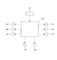
図2に示すように、制御手段である制御装置130の出力部には、前記第一の版胴112を回転駆動させるサーボモータ117と、前記第一のブランケット胴113を回転駆動させるサーボモータ118と、前記第一のスライド部材114を介して前記ガイドレール102に沿って前記第一の移動フレーム115を往復移動させる第一の移動用駆動装置119と、前記第二の版胴122を回転駆動させるサーボモータ127と、前記第二のブランケット胴123を回転駆動させるサーボモータ128と、前記第二のスライド部材124を介して前記ガイドレール102に沿って前記第二の移動フレーム125を往復移動させる第二の移動用駆動装置129と、前記送給軸141を回転駆動させる駆動モータ148と、前記回収軸142を回転駆動させる駆動モータ149とがそれぞれ電気的に接続されている。前記制御装置130の入力部には、当該制御装置130に各種信号を入力する入力装置131が接続されており、当該制御装置130は、入力装置131からの信号等に基づいて、前記モータ117,118,127,128,148,149及び前記移動用駆動装置119,129の作動を制御することができるようになっている(詳細は後述する)。
このような本実施形態においては、前記サーボモータ117,118等により、第一の受渡作動手段を構成し、前記サーボモータ127,128等により、第二の受渡作動手段を構成し、前記ガイドレール102、前記第一のスライド部材114、前記第一の移動フレーム115、前記サーボモータ118、前記第一の移動用駆動装置119等により、第一の転写作動手段を構成し、前記ガイドレール102、前記第二のスライド部材124、前記第二の移動フレーム125、前記サーボモータ128、前記第二の移動用駆動装置129等により、第二の転写作動手段を構成し、前記送給軸141、前記ガイドローラ145,146、前記駆動モータ148等により、対象体送給手段を構成し、前記回収軸142、前記サクションローラ143、前記ガイドローラ144、前記駆動モータ149等により、対象体回収手段を構成している。
次に、本実施形態に係るグラビアオフセット印刷機100の作動を説明する。
前記送給軸141に巻き付けられている前記基材1を、前記ガイドローラ145,146を介して前記ステージ103上を経由させ、前記ガイドローラ144及び前記サクションローラ143を介して前記回収軸142に巻き付けると共に、前記第一,二の版胴112,122と前記第一,二のドクタブレード113,123との間に前記インキ2を供給して、前記入力装置131で作動開始信号を入力すると、前記制御装置130は、前記第一の版胴112及び前記第一のブランケット胴116を回転させるように前記サーボモータ117,118を作動制御することにより、当該第一の版胴112の前記凹版の前記絵柄に上記インキ2を供給すると共に当該凹版の当該絵柄以外の部分から当該インキ2を上記第一のドクタブレード113で除去しながら、当該第一のブランケット胴116の前記シリコーンブランケット上に上記インキ2を上記絵柄に対応した状態で受け渡す(図3A参照)。
このようにして前記第一のブランケット胴116の前記シリコーンブランケット上に前記インキ2が受け渡されると、前記制御装置130は、前記第一のスライド部材114を介して前記ガイドレール102に沿って前記第一の移動フレーム115を前記第二の固定フレーム121側へ向けて移動させるように前記第一の移動用駆動装置119を作動制御して、当該第一のブランケット胴116を前記第二の版胴122側(図3中、左側)へ向けて移動させると共に、これと並行して、前記第二の版胴122及び前記第二のブランケット胴126を回転させるように前記サーボモータ127,128を作動制御する(図3B参照)。
これにより、前記第一のブランケット胴116が前記ステージ103上を転動して、前記シリコーンブランケット上の前記インキ2が当該基材1上に転写されて印刷されると共に、これと並行して、前記第二の版胴122の前記凹版の前記絵柄に前記インキ2が供給され、当該凹版の当該絵柄以外の部分から当該インキ2が前記第二のドクタブレード123で除去されながら、前記第二のブランケット胴126の前記シリコーンブランケット上に上記インキ2が上記絵柄に対応した状態で受け渡される(図3B参照)。
このとき、前記インキ2を前記第一の版胴112の前記凹版の前記絵柄の線幅等に対応する適切な条件に調整しておくことにより、当該第一の版胴112の当該凹版から前記第一のブランケット胴116の前記シリコーンブランケット上に受け渡されて前記基材1へ転写されるまでの間に生乾きのような状態になって凝集力を増大させることができるので、当該インキ2は、上記シリコーンブランケット上から上記基材1へ転写(放出)されやすくなり、当該基材1へすべて転写するようになる。
このようにして前記基材1上に前記インキ2が転写されて印刷されると、前記制御装置130は、前記第一のスライド部材114を介して前記ガイドレール102に沿って前記第一の移動フレーム115を前記第一の固定フレーム111側へ向けて移動させるように前記第一の移動用駆動装置119を作動制御して、当該第一のブランケット胴116を当初の位置に戻すように前記第一の版胴112側(図3中、右側)へ向けて移動させて、当該第一のブランケット胴116を当該第一の版胴112に対接させると共に、前記ステージ103上の前記基材1を所定長移動させるように前記駆動モータ148,149を作動制御することにより、前記送給軸141から前記基材1を繰り出し送給すると共に前記回収軸142に前記基材1を巻き取り回収する一方、これと並行して、前記第二のスライド部材124を介して前記ガイドレール102に沿って前記第二の移動フレーム125を前記第一の固定フレーム111側へ向けて移動させるように前記第二の移動用駆動装置129を作動制御して、当該第二のブランケット胴126を前記第一の版胴112側(図3中、右側)へ向けて移動させる(図3C参照)。
これにより、前記第一の版胴112の前記凹版の前記絵柄に前記インキ2が再び供給され、当該凹版の当該絵柄以外の部分から当該インキ2が前記第一のドクタブレード113で除去されながら、前記第一のブランケット胴116の前記シリコーンブランケット上に上記インキ2が上記絵柄に対応した状態で再び受け渡されると共に、これと並行して、前記第二のブランケット胴126が、前記ステージ103上を転動して、前記シリコーンブランケット上の前記インキ2が、当該ステージ103上に新たに位置した基材1上に転写されて印刷される(図3C参照)。
このとき、前記インキ2を前記第二の版胴122の前記凹版の前記絵柄の線幅等に対応する適切な条件に調整しておくことにより、当該第二の版胴122の当該凹版から前記第二のブランケット胴126の前記シリコーンブランケット上に受け渡されて前記基材1へ転写されるまでの間に生乾きのような状態になって凝集力を増大させることができるので、当該インキ2は、上記シリコーンブランケット上から上記基材1へ転写(放出)されやすくなり、当該基材1へすべて転写するようになる。
このようにして前記ステージ103上に新たに位置させた前記基材1上に前記インキ2が転写されて印刷されると、前記制御装置130は、前記第二のスライド部材124を介して前記ガイドレール102に沿って前記第二の移動フレーム125を前記第二の固定フレーム121側へ向けて移動させるように前記第二の移動用駆動装置129を作動制御して、当該第二のブランケット胴126を当初の位置に戻すように前記第二の版胴112側(図3中、左側)へ向けて移動させて、当該第一のブランケット胴116を当該第一の版胴112に対接させると共に、前記ステージ103上の前記基材1を再び所定長移動させるように前記駆動モータ148,149を作動制御することにより、前記送給軸141から前記基材1を再び繰り出し送給すると共に前記回収軸142に前記基材1を再び巻き取り回収する一方、これと並行して、前記第一のスライド部材114を介して前記ガイドレール102に沿って前記第一の移動フレーム115を前記第二の固定フレーム121側へ向けて移動させるように前記第一の移動用駆動装置119を作動制御して、当該第一のブランケット胴116を前記第二の版胴122側(図3中、左側)へ向けて移動させる(図3B参照)。
以下、上述した作動を繰り返すことにより、前記絵柄に対応した前記インキ2を前記基材1に連続的に転写して印刷することができる。
つまり、本実施形態に係るグラビアオフセット印刷機100では、前記第一のブランケット胴116から前記基材1への前記インキ2の転写(第一の転写工程)と前記第二の版胴122から前記第二のブランケット胴126への前記インキ2の受け渡し(第二の受渡工程)とを並行して行う、すなわち、前記第一の転写工程を行っている最中に前記第二の受渡工程を行う、言い換えれば、前記第二の受渡工程を行っている最中に前記第一の転写工程を行うことができるようにすると共に、前記第二のブランケット胴126から前記基材1への前記インキ2の転写(第二の転写工程)と前記第一の版胴112から前記第一のブランケット胴116への前記インキ2の受け渡し(第一の受渡工程)とを並行して行う、すなわち、前記第二の転写工程を行っている最中に前記第一の受渡工程を行う、言い換えれば、前記第一の受渡工程を行っている最中に前記第二の転写工程を行うことができるようにしたのである。
したがって、本実施形態に係るグラビアオフセット印刷機100によれば、タクトタイムを短縮して生産性を向上させることができる。
また、ウエブ状の基材1を前記ステージ103上に順次繰り出し送給するようにしたことから、シート状の基材の場合よりもタクトタイムをさらに短縮して生産性をさらに向上させることができる。
〈第二番目の実施形態〉
本発明に係るグラビアオフセット印刷機の第二番目の実施形態を図4~6に基づいて説明する。なお、前述した実施形態と同様な部分については、前述した実施形態の説明で用いた符号と同様な符号を用いることにより、前述した実施形態での説明と重複する説明を省略する。
本発明に係るグラビアオフセット印刷機の第二番目の実施形態を図4~6に基づいて説明する。なお、前述した実施形態と同様な部分については、前述した実施形態の説明で用いた符号と同様な符号を用いることにより、前述した実施形態での説明と重複する説明を省略する。
図4に示すように、前記フラットベッド101の長手方向(図4中、左右方向)一方端側(図4中、右側)の上面には、絵柄を形成された平板状の第一の凹版(グラビア版)212が配設されている。前記フラットベッド101の長手方向他方端側(図4中、左側)の上面には、絵柄を形成された平板状の第二の凹版(グラビア版)222が配設されている。
前記第一の移動フレーム115には、シリコーンブランケットを外周に巻き付けた第一のブランケット胴(シリコーンブランケット胴)216が前記フラットベッド101の幅方向へ軸方向を向けて回転可能に支持されており、当該第一のブランケット胴216は、前記ステージ103の上面や前記第一の凹版212に対して当接離反できるように昇降移動可能になっている。
前記第二の移動フレーム125には、シリコーンブランケットを外周に巻き付けた第二のブランケット胴(シリコーンブランケット胴)226が前記フラットベッド101の幅方向へ軸方向を向けて回転可能に支持されており、当該第二のブランケット胴226は、前記ステージ103の上面や前記第一の凹版222に対して当接離反できるように昇降移動可能になっている。
前記第一の移動フレーム115の、前記第一のブランケット胴216よりも前記第二のブランケット胴226側には、第一のドクタブレード213の基端側が回動可能に支持されており、当該第一のドクタブレード213は、前記第一の凹版212の上方に位置しているときに先端側を下方へ向けると当該第一の凹版212の上面に当接することができるようになっている。前記第一のドクタブレード213の下方側には、インキ2が供給されるようになっている。
前記第二の移動フレーム125の、前記第二のブランケット胴226よりも前記第一のブランケット胴216側には、第二のドクタブレード223の基端側が回動可能に支持されており、当該第二のドクタブレード223は、前記第二の凹版222の上方に位置しているときに先端側を下方へ向けると当該第一の凹版212の上面に当接することができるようになっている。前記第二のドクタブレード223の下方側には、インキ2が供給されるようになっている。
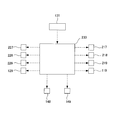
図5に示すように、前記移動用駆動装置119,129及び前記駆動モータ148,149並びに前記第一のブランケット胴216を駆動回転させるサーボモータ218及び前記第二のブランケット胴226を駆動回転させるサーボモータ228は、制御手段である制御装置230の出力部にそれぞれ電気的に接続している。前記制御装置230の出力部は、前記第一のドクタブレード213を回動させるアクチュエータ217と、前記第二のドクタブレード223を回動させるアクチュエータ227と、前記第一のブランケット胴216を昇降移動させるアクチュエータ219と、前記第二のブランケット胴226を昇降移動させるアクチュエータ229とにそれぞれ電気的に接続しており、当該制御装置230は、前記入力装置131からの信号等に基づいて、前記移動用駆動装置119,129、前記モータ148,149,218,228、前記アクチュエータ217,219,227,229の作動を制御することができるようになっている(詳細は後述する)。
つまり、前述した実施形態に係るグラビアオフセット印刷機100は、円凹版タイプであったが、本実施形態に係るグラビアオフセット印刷機200は、平凹版タイプなのである。
このような本実施形態においては、前記ガイドレール102、前記第一のスライド部材114、前記第一の移動フレーム115、前記第一の移動用駆動装置119、前記サーボモータ218、前記アクチュエータ219等により、第一の受渡作動手段と第一の転写作動手段とを兼ねるように構成し、前記ガイドレール102、前記第二のスライド部材124、前記第二の移動フレーム125、前記第二の移動用駆動装置129、前記サーボモータ228、前記アクチュエータ229等により、第二の受渡作動手段と第二の転写作動手段とを兼ねるように構成している。
次に、本実施形態に係るグラビアオフセット印刷機200の作動を説明する。
前記送給軸141に巻き付けられている前記基材1を、前記ガイドローラ145,146を介して前記ステージ103上を経由させ、前記ガイドローラ144及び前記サクションローラ143を介して前記回収軸142に巻き付けると共に、前記第一,二のドクタブレード213,223の下方の前記第一,二の凹版212,222上に前記インキ2を供給して、前記入力装置131で作動開始信号を入力すると、前記制御装置230は、前記第一のブランケット胴216を上昇させるように前記アクチュエータ219を作動制御することにより、当該第一のブランケット胴216を前記第一の凹版212から離反させると共に、前記第一のドクタブレード216の先端側を下方に位置させるように前記アクチュエータ217を作動制御することにより、当該第一のドクタブレード216の先端側を前記第一の凹版212に当接させた後、前記第一の移動フレーム115を前記第二の移動フレーム125から離反させる方向(図6中、右側)へ移動させるように前記第一の移動用駆動装置119を作動制御することにより、前記インキ2を上記第一の凹版212の前記絵柄に供給すると共に当該絵柄以外の部分から上記第一のドクタブレード213で除去する(図6A参照)。
このようにして前記第一の凹版212の前記絵柄に前記インキ2が供給されると、前記制御装置230は、前記第一のドクタブレード213の先端側を上方に位置させるように前記アクチュエータ217を作動制御することにより、当該第一のドクタブレード213の先端側を上記第一の凹版212から離反させると共に、前記第一のブランケット胴216を下降させるように前記アクチュエータ219を作動制御することにより、当該第一のブランケット胴216を上記第一の凹版212に当接させた後、当該第一のブランケット胴216を回転させるように前記サーボモータ218を作動制御すると共に、前記第一の移動フレーム115を前記第二の移動フレーム125側(図6中、左側)へ向けて移動させるように前記第一の移動用駆動装置119を作動制御することにより、上記第一の凹版212の前記絵柄に供給されていた前記インキ2を当該絵柄に対応させた状態のまま上記第一のブランケット胴216の前記シリコーンブランケット上に受け渡す(図6B参照)。
そして、前記制御装置230は、前記第一の移動フレーム115をそのまま引き続いて移動させる、すなわち、前記ステージ103の一方端(図6中、右側)から他方端(図6中、左側)へ向けて前記第一のブランケット胴216を移動させることにより、当該第一のブランケット胴216の前記シリコーンブランケット上の前記第一のインキ2Aを前記基材1上に転写して印刷する。
これと並行して、前記制御装置230は、前記第二のブランケット胴226を上昇させるように前記アクチュエータ229を作動制御することにより、当該第二のブランケット胴226を前記第二の凹版222から離反させると共に、前記第二のドクタブレード223の先端側を下方に位置させるように前記アクチュエータ227を作動制御することにより、当該第二のドクタブレード223の先端側を前記第二の凹版222に当接させた後、前記第二の移動フレーム125を前記第一の移動フレーム115から離反させる方向(図6中、左側)へ移動させるように前記第二の移動用駆動装置129を作動制御することにより、前記インキ2を上記第二の凹版222の前記絵柄に供給すると共に当該絵柄以外の部分から上記第二のドクタブレード223で除去する(図6B参照)。
そして、前記制御装置230は、当前記第二のドクタブレード223の先端側を上方に位置させるように前記アクチュエータ227を作動制御することにより、当該第二のドクタブレード223の先端側を上記第二の凹版222から離反させると共に、前記第二のブランケット胴226を下降させるように前記アクチュエータ229を作動制御することにより、当該第二のブランケット胴226を上記第二の凹版222に当接させた後、当該第二のブランケット胴226を回転させるように前記サーボモータ228を作動制御すると共に、前記第二の移動フレーム125を前記第一の移動フレーム115側(図6中、右側)へ向けて移動させるように前記第二の移動用駆動装置129を作動制御することにより、上記第二の凹版222の前記絵柄に供給されていた前記インキ2を当該絵柄に対応させた状態のまま上記第二のブランケット胴226の前記シリコーンブランケット上に受け渡す(図6C参照)。
これと並行して、前記制御装置230は、前記インキ2を前記基材1に転写して印刷し終えた前記第一のブランケット胴216を上昇させるように前記アクチュエータ219を作動制御することにより、当該第一のブランケット胴216を上記基材1から離反させると共に、前記第一の移動フレーム115を前記第二の移動フレーム125から離反させる方向(図6中、右方向)へ移動させるように前記第一の移動用駆動装置119を作動制御することにより、当該第一の移動フレーム115を当初の位置に戻し、前記ステージ103上の前記基材1を所定長移動させるように前記駆動モータ148,149を作動制御することにより、前記送給軸141から前記基材1を繰り出し送給すると共に前記回収軸142に前記基材1を巻き取り回収する一方、前記第一のドクタブレード216の先端側を下方に位置させるように前記アクチュエータ217を作動制御することにより、当該第一のドクタブレード216の先端側を前記第一の凹版212に再び当接させ、上記第一の移動フレーム115を前記第二の移動フレーム125から離反させる方向(図6中、右側)へ再び移動させるように前記第一の移動用駆動装置119を作動制御することにより、前記インキ2を上記第一の凹版212の前記絵柄に再び供給すると共に当該絵柄以外の部分から上記第一のドクタブレード213で再び除去する(図6C参照)。
他方、前記制御装置230は、前記第一の移動フレーム115の上記移動と並行して、前記第二の移動フレーム125をそのまま引き続いて移動させる、すなわち、前記ステージ103の他方端(図6中、左側)から一方端(図6中、右側)へ向けて前記第二のブランケット胴226を移動させることにより、当該ステージ103上に新たに位置した基材1上に上記第二のブランケット胴216の前記シリコーンブランケット上の前記インキ2を転写して印刷する。
そして、前記制御装置230は、前記インキ2を前記基材1に転写して印刷し終えた前記第二のブランケット胴226を上昇させるように前記アクチュエータ229を作動制御することにより、当該第二のブランケット胴226を上記基材1から離反させると共に、前記第二の移動フレーム125を前記第一の移動フレーム115から離反させる方向(図6中、左側)へ移動させるように前記第二の移動用駆動装置129を作動制御することにより、当該第二の移動フレーム125を当初の位置に戻して、前記ステージ103上の前記基材1を再び所定長移動させるように前記駆動モータ148,149を作動制御することにより、前記送給軸141から前記基材1を再び繰り出し送給すると共に前記回収軸142に前記基材1を再び巻き取り回収する一方、前記第二のドクタブレード223の先端側を下方に位置させるように前記アクチュエータ227を作動制御することにより、当該第二のドクタブレード223の先端側を前記第二の凹版222に再び当接させた後、上記第二の移動フレーム125を前記第一の移動フレーム115から離反させる方向(図6中、左側)へ再び移動させるように前記第二の移動用駆動装置129を作動制御することにより、前記インキ2を上記第二の凹版222の前記絵柄に再び供給すると共に当該絵柄以外の部分から上記第二のドクタブレード223で再び除去する(図6B参照)。
以下、上述した作動を繰り返すことにより、前述した実施形態の場合と同様に、前記絵柄に対応した前記インキ2を前記基材1に連続的に転写して印刷することができる。
したがって、本実施形態に係るグラビアオフセット印刷機200によれば、前述した実施形態の場合と同様な作用効果を発現し得ることができる。
〈他の実施形態〉
なお、前述した実施形態においては、前記インキ2を前記版胴112,122の前記凹版の前記絵柄の線幅等に対応する適切な条件に調整しておくことにより、当該版胴112,122の当該凹版から前記ブランケット胴116,126の前記シリコーンブランケット上に受け渡されて前記基材1へ転写されるまでの間に生乾きのような状態にして凝集力を増大させるようにしたが、他の実施形態として、例えば、前記版胴112,122の前記凹版の前記絵柄の線幅等に対応して前記ブランケット胴116,126,216,226の移動速度、すなわち、前記受渡工程と前記転写工程との間の時間(インターバル)を適切な条件に調整することにより、当該版胴112,122の当該凹版から前記ブランケット胴116,126の前記シリコーンブランケット上に受け渡されて前記基材1へ転写されるまでの間に前記インキ2を生乾きのような状態にして凝集力を増大させるようにすることも可能である。さらに、前記インキ2の条件調整と前記インターバルの条件調整とを組み合わせて、より最適な条件で印刷できるようにすることも可能である。
なお、前述した実施形態においては、前記インキ2を前記版胴112,122の前記凹版の前記絵柄の線幅等に対応する適切な条件に調整しておくことにより、当該版胴112,122の当該凹版から前記ブランケット胴116,126の前記シリコーンブランケット上に受け渡されて前記基材1へ転写されるまでの間に生乾きのような状態にして凝集力を増大させるようにしたが、他の実施形態として、例えば、前記版胴112,122の前記凹版の前記絵柄の線幅等に対応して前記ブランケット胴116,126,216,226の移動速度、すなわち、前記受渡工程と前記転写工程との間の時間(インターバル)を適切な条件に調整することにより、当該版胴112,122の当該凹版から前記ブランケット胴116,126の前記シリコーンブランケット上に受け渡されて前記基材1へ転写されるまでの間に前記インキ2を生乾きのような状態にして凝集力を増大させるようにすることも可能である。さらに、前記インキ2の条件調整と前記インターバルの条件調整とを組み合わせて、より最適な条件で印刷できるようにすることも可能である。
本発明に係るグラビアオフセット印刷機は、タクトタイムを短縮して生産性を向上させることができるので、プリンテッドエレクトロニクス(PE)分野を始めとする各種印刷産業において、極めて有益に利用することができる。
1 基材
2 インキ
100 グラビアオフセット印刷機
101 フラットベッド
101a,101b 切欠き
102 ガイドレール
103 ステージ
111 第一の固定フレーム
112 第一の版胴
113 第一のドクタブレード
114 第一のスライド部材
115 第一の移動フレーム
116 第一のブランケット胴
117 サーボモータ
118 サーボモータ
119 第一の移動用駆動装置
121 第二の固定フレーム
122 第二の版胴
123 第二のドクタブレード
124 第二のスライド部材
125 第二の移動フレーム
126 第二のブランケット胴
127 サーボモータ
128 サーボモータ
129 第二の移動用駆動装置
130 制御装置
131 入力装置
141 送給軸
142 回収軸
143 サクションローラ
144~146 ガイドローラ
148 駆動モータ
149 駆動モータ
200 グラビアオフセット印刷機
212 第一の凹版
213 第一のドクタブレード
216 第一のブランケット胴
217 アクチュエータ
218 サーボモータ
219 アクチュエータ
222 第二の凹版
223 第二のドクタブレード
226 第二のブランケット胴
227 アクチュエータ
228 サーボモータ
229 アクチュエータ
230 制御装置
2 インキ
100 グラビアオフセット印刷機
101 フラットベッド
101a,101b 切欠き
102 ガイドレール
103 ステージ
111 第一の固定フレーム
112 第一の版胴
113 第一のドクタブレード
114 第一のスライド部材
115 第一の移動フレーム
116 第一のブランケット胴
117 サーボモータ
118 サーボモータ
119 第一の移動用駆動装置
121 第二の固定フレーム
122 第二の版胴
123 第二のドクタブレード
124 第二のスライド部材
125 第二の移動フレーム
126 第二のブランケット胴
127 サーボモータ
128 サーボモータ
129 第二の移動用駆動装置
130 制御装置
131 入力装置
141 送給軸
142 回収軸
143 サクションローラ
144~146 ガイドローラ
148 駆動モータ
149 駆動モータ
200 グラビアオフセット印刷機
212 第一の凹版
213 第一のドクタブレード
216 第一のブランケット胴
217 アクチュエータ
218 サーボモータ
219 アクチュエータ
222 第二の凹版
223 第二のドクタブレード
226 第二のブランケット胴
227 アクチュエータ
228 サーボモータ
229 アクチュエータ
230 制御装置
Claims (2)
- ウエブ状の対象体を繰り出しながら送給する対象体送給手段と、
前記対象体送給手段から繰り出された前記対象体を巻き取り回収する対象体回収手段と、
インキを供給される第一のグラビア版と、
前記第一のグラビア版から前記インキを受け取って、前記対象体送給手段から繰り出された前記対象体に転写する第一のシリコーンブランケット胴と、
前記第一のグラビア版から前記第一のシリコーンブランケット胴に前記インキを受け渡すように当該第一のグラビア版及び当該第一のシリコーンブランケット胴のうち少なくとも当該第一のシリコーンブランケット胴を作動させる第一の受渡作動手段と、
前記対象体送給手段から繰り出された前記対象体に前記第一のシリコーンブランケット胴の前記インキを転写するように当該第一のシリコーンブランケット胴を作動させる第一の転写作動手段と、
インキを供給される第二のグラビア版と、
前記第二のグラビア版から前記インキを受け取って、前記対象体送給手段から繰り出された前記対象体に転写する第二のシリコーンブランケット胴と、
前記第二のグラビア版から前記第二のシリコーンブランケット胴に前記インキを受け渡すように当該第二のグラビア版及び当該第二のシリコーンブランケット胴のうち少なくとも当該第二のシリコーンブランケット胴を作動させる第二の受渡作動手段と、
前記対象体送給手段から繰り出された前記対象体に前記第二のシリコーンブランケット胴の前記インキを転写するように当該第二のシリコーンブランケット胴を作動させる第二の転写作動手段と、
前記第一のシリコーンブランケット胴から前記対象体への前記インキの転写と前記第二のグラビア版から前記第二のシリコーンブランケット胴への前記インキの受け渡しとを並行して行うように前記第一の転写作動手段及び前記第二の受渡作動手段の作動を制御する制御手段と
を備えていることを特徴とするグラビアオフセット印刷機。 - 請求項1に記載のグラビアオフセット印刷機において、
前記制御手段が、前記第二のシリコーンブランケット胴から前記対象体への前記インキの転写と前記第一のグラビア版から前記第一のシリコーンブランケット胴への前記インキの受け渡しとを並行して行うように前記第二の転写作動手段及び前記第一の受渡作動手段の作動を制御するものである
ことを特徴とするグラビアオフセット印刷機。
Priority Applications (2)
| Application Number | Priority Date | Filing Date | Title |
|---|---|---|---|
| CN201380051071.8A CN104703800A (zh) | 2012-10-05 | 2013-09-30 | 照相凹版胶印机 |
| KR1020157008421A KR102105106B1 (ko) | 2012-10-05 | 2013-09-30 | 그라비어 오프셋 인쇄기 |
Applications Claiming Priority (2)
| Application Number | Priority Date | Filing Date | Title |
|---|---|---|---|
| JP2012-222856 | 2012-10-05 | ||
| JP2012222856A JP6112502B2 (ja) | 2012-10-05 | 2012-10-05 | グラビアオフセット印刷機 |
Publications (1)
| Publication Number | Publication Date |
|---|---|
| WO2014054555A1 true WO2014054555A1 (ja) | 2014-04-10 |
Family
ID=50434882
Family Applications (1)
| Application Number | Title | Priority Date | Filing Date |
|---|---|---|---|
| PCT/JP2013/076478 Ceased WO2014054555A1 (ja) | 2012-10-05 | 2013-09-30 | グラビアオフセット印刷機 |
Country Status (5)
| Country | Link |
|---|---|
| JP (1) | JP6112502B2 (ja) |
| KR (1) | KR102105106B1 (ja) |
| CN (2) | CN107399146B (ja) |
| TW (1) | TWI597179B (ja) |
| WO (1) | WO2014054555A1 (ja) |
Cited By (1)
| Publication number | Priority date | Publication date | Assignee | Title |
|---|---|---|---|---|
| JP2016168749A (ja) * | 2015-03-13 | 2016-09-23 | 株式会社小森コーポレーション | 印刷機 |
Families Citing this family (4)
| Publication number | Priority date | Publication date | Assignee | Title |
|---|---|---|---|---|
| KR101744857B1 (ko) * | 2014-07-29 | 2017-06-08 | 주식회사 엘지화학 | 터치 패널 제조 시스템 |
| JP6322527B2 (ja) * | 2014-09-10 | 2018-05-09 | 株式会社Screenホールディングス | 印刷装置、印刷方法および該印刷装置で用いる担持体 |
| JP6572050B2 (ja) * | 2015-08-05 | 2019-09-04 | 株式会社小森コーポレーション | 印刷機 |
| CN108271317A (zh) * | 2017-12-29 | 2018-07-10 | 上海量子绘景电子股份有限公司 | 一种基于凹版印刷工艺的线路板的制备方法 |
Citations (4)
| Publication number | Priority date | Publication date | Assignee | Title |
|---|---|---|---|---|
| JPH09207305A (ja) * | 1996-02-07 | 1997-08-12 | Canon Inc | オフセット印刷装置、及び画像形成装置 |
| JP2006205470A (ja) * | 2005-01-26 | 2006-08-10 | Mitsubishi Heavy Ind Ltd | 単色印刷機およびその運転方法 |
| JP2006289983A (ja) * | 2005-04-13 | 2006-10-26 | Korea Mach Res Inst | ロールツーロール輪転印刷法を用いた電子素子の製造方法及び製造装置 |
| JP2008166115A (ja) * | 2006-12-28 | 2008-07-17 | Mitsubishi Materials Corp | プラズマディスプレイパネルの製造方法 |
Family Cites Families (13)
| Publication number | Priority date | Publication date | Assignee | Title |
|---|---|---|---|---|
| IT1148377B (it) * | 1981-08-06 | 1986-12-03 | Roland Man Druckmasch | Macchina da stampa rotativa |
| DD269356A1 (de) * | 1988-02-04 | 1989-06-28 | Polygraph Leipzig | Bildtransportdruckmaschine |
| JP3402974B2 (ja) | 1996-12-17 | 2003-05-06 | 三菱重工業株式会社 | 平台印刷機 |
| JP2005035143A (ja) | 2003-07-18 | 2005-02-10 | Tohoku Ricoh Co Ltd | 印刷装置・印刷装置の駆動方法 |
| JP2005186597A (ja) | 2003-12-26 | 2005-07-14 | Sumitomo Rubber Ind Ltd | 導電性パターンの製造方法 |
| JP4814309B2 (ja) * | 2005-03-30 | 2011-11-16 | ゴス インターナショナル アメリカス インコーポレイテッド | ブランケット胴胴抜き支持面を有する印刷ユニット |
| JP5020642B2 (ja) * | 2007-01-15 | 2012-09-05 | 阪本 順 | 印刷装置、印刷方法および多層構造形成方法 |
| DE102009002228B4 (de) | 2009-04-06 | 2015-01-08 | Koenig & Bauer Aktiengesellschaft | Lackierwerk einer Rollen-Rotations-Offsetdruckmaschine |
| JP5218352B2 (ja) * | 2009-09-09 | 2013-06-26 | 株式会社Ihi | オフセット印刷方法及び装置 |
| JP2011201131A (ja) | 2010-03-25 | 2011-10-13 | Dainippon Printing Co Ltd | グラビア印刷機およびその制御方法 |
| JP2011230348A (ja) * | 2010-04-27 | 2011-11-17 | Komori Corp | グラビア印刷機 |
| JP5438593B2 (ja) * | 2010-05-18 | 2014-03-12 | 株式会社小森コーポレーション | グラビアオフセット印刷機 |
| JP5743295B2 (ja) * | 2011-02-24 | 2015-07-01 | エルジー・ケム・リミテッド | ロールプリンティング装置およびそれを用いたロールプリンティング方法 |
-
2012
- 2012-10-05 JP JP2012222856A patent/JP6112502B2/ja not_active Expired - Fee Related
-
2013
- 2013-09-30 KR KR1020157008421A patent/KR102105106B1/ko not_active Expired - Fee Related
- 2013-09-30 WO PCT/JP2013/076478 patent/WO2014054555A1/ja not_active Ceased
- 2013-09-30 CN CN201710379457.1A patent/CN107399146B/zh not_active Expired - Fee Related
- 2013-09-30 CN CN201380051071.8A patent/CN104703800A/zh active Pending
- 2013-10-04 TW TW102136095A patent/TWI597179B/zh not_active IP Right Cessation
Patent Citations (4)
| Publication number | Priority date | Publication date | Assignee | Title |
|---|---|---|---|---|
| JPH09207305A (ja) * | 1996-02-07 | 1997-08-12 | Canon Inc | オフセット印刷装置、及び画像形成装置 |
| JP2006205470A (ja) * | 2005-01-26 | 2006-08-10 | Mitsubishi Heavy Ind Ltd | 単色印刷機およびその運転方法 |
| JP2006289983A (ja) * | 2005-04-13 | 2006-10-26 | Korea Mach Res Inst | ロールツーロール輪転印刷法を用いた電子素子の製造方法及び製造装置 |
| JP2008166115A (ja) * | 2006-12-28 | 2008-07-17 | Mitsubishi Materials Corp | プラズマディスプレイパネルの製造方法 |
Cited By (1)
| Publication number | Priority date | Publication date | Assignee | Title |
|---|---|---|---|---|
| JP2016168749A (ja) * | 2015-03-13 | 2016-09-23 | 株式会社小森コーポレーション | 印刷機 |
Also Published As
| Publication number | Publication date |
|---|---|
| TW201422449A (zh) | 2014-06-16 |
| CN107399146A (zh) | 2017-11-28 |
| CN107399146B (zh) | 2019-08-09 |
| KR20150068373A (ko) | 2015-06-19 |
| KR102105106B1 (ko) | 2020-04-27 |
| JP6112502B2 (ja) | 2017-04-12 |
| CN104703800A (zh) | 2015-06-10 |
| JP2014073652A (ja) | 2014-04-24 |
| TWI597179B (zh) | 2017-09-01 |
Similar Documents
| Publication | Publication Date | Title |
|---|---|---|
| JP6112502B2 (ja) | グラビアオフセット印刷機 | |
| JP2011161661A (ja) | スクリーン印刷機及び印刷方法 | |
| CN108025547B (zh) | 印刷装置以及用于使印刷装置中的刮刀装置运行的方法 | |
| US10442185B2 (en) | Cleaning arrangement and method for cleaning a flexographic coating unit | |
| JP2008074102A (ja) | シートを印刷する機械において片面印刷から両面印刷へ運転形式を切り換える方法および装置 | |
| CN114379206A (zh) | 旋转丝网印刷机刮刀装置 | |
| JP3792215B2 (ja) | 輪転印刷機の印刷装置に用いられる横方向レジスタを調節するための装置 | |
| EP2835257A2 (en) | Proof printing press | |
| JP6386119B2 (ja) | グラビアオフセット印刷機 | |
| JP6112501B2 (ja) | グラビアオフセット印刷機 | |
| CN107107605A (zh) | 用于丝网印刷机的刮刀装置以及用于运行刮刀装置的方法 | |
| JP2010260721A5 (ja) | ||
| JP6290482B2 (ja) | グラビアオフセット印刷機 | |
| TWI698352B (zh) | 印刷機 | |
| TWI627070B (zh) | 無紙化轉移印花機 | |
| JP2009096201A (ja) | 加工機における印刷版交換方法及び交換装置 | |
| JP2016168837A (ja) | 印刷機 | |
| JPWO2017043564A1 (ja) | シート搬送装置 | |
| JP2017189928A (ja) | 電子デバイス製造装置 | |
| JP6576140B2 (ja) | 両面印刷を行う装置 | |
| JP6124053B2 (ja) | 圧胴押圧機構、印刷ユニットおよび圧胴の押圧方法 | |
| JPH09248896A (ja) | 案内要素の軸方向移動調整装置 | |
| WO2015166788A1 (ja) | 凹版印刷機 | |
| KR100727042B1 (ko) | 다기능 인쇄유닛 | |
| JP2017189929A (ja) | 電子デバイス製造装置 |
Legal Events
| Date | Code | Title | Description |
|---|---|---|---|
| 121 | Ep: the epo has been informed by wipo that ep was designated in this application |
Ref document number: 13843435 Country of ref document: EP Kind code of ref document: A1 |
|
| ENP | Entry into the national phase |
Ref document number: 20157008421 Country of ref document: KR Kind code of ref document: A |
|
| NENP | Non-entry into the national phase |
Ref country code: DE |
|
| 122 | Ep: pct application non-entry in european phase |
Ref document number: 13843435 Country of ref document: EP Kind code of ref document: A1 |