WO2014054476A1 - Dispositif de commande de direction - Google Patents
Dispositif de commande de direction Download PDFInfo
- Publication number
- WO2014054476A1 WO2014054476A1 PCT/JP2013/075801 JP2013075801W WO2014054476A1 WO 2014054476 A1 WO2014054476 A1 WO 2014054476A1 JP 2013075801 W JP2013075801 W JP 2013075801W WO 2014054476 A1 WO2014054476 A1 WO 2014054476A1
- Authority
- WO
- WIPO (PCT)
- Prior art keywords
- steering
- reaction force
- white line
- steering reaction
- torque
- Prior art date
Links
Images


Classifications
-
- B—PERFORMING OPERATIONS; TRANSPORTING
- B62—LAND VEHICLES FOR TRAVELLING OTHERWISE THAN ON RAILS
- B62D—MOTOR VEHICLES; TRAILERS
- B62D6/00—Arrangements for automatically controlling steering depending on driving conditions sensed and responded to, e.g. control circuits
- B62D6/008—Control of feed-back to the steering input member, e.g. simulating road feel in steer-by-wire applications
-
- B—PERFORMING OPERATIONS; TRANSPORTING
- B62—LAND VEHICLES FOR TRAVELLING OTHERWISE THAN ON RAILS
- B62D—MOTOR VEHICLES; TRAILERS
- B62D15/00—Steering not otherwise provided for
- B62D15/02—Steering position indicators ; Steering position determination; Steering aids
- B62D15/025—Active steering aids, e.g. helping the driver by actively influencing the steering system after environment evaluation
-
- G—PHYSICS
- G06—COMPUTING; CALCULATING OR COUNTING
- G06V—IMAGE OR VIDEO RECOGNITION OR UNDERSTANDING
- G06V20/00—Scenes; Scene-specific elements
- G06V20/50—Context or environment of the image
- G06V20/56—Context or environment of the image exterior to a vehicle by using sensors mounted on the vehicle
- G06V20/588—Recognition of the road, e.g. of lane markings; Recognition of the vehicle driving pattern in relation to the road
Definitions
- the present invention relates to a steering control device.
- Patent Document 1 when approaching one of the left and right white lines of the driving lane recognized from the image of the in-vehicle camera, steering control that assists the driver's steering by turning the steered wheel in a direction away from the white line.
- An apparatus is disclosed.
- the control amount of the control for assisting the driver's steering is one of the left and right white lines. Because it is based on the relationship with the Even in this case, it is necessary to interrupt the control for assisting the driver's steering.
- the driver is steering on the assumption of a change in the steering reaction force caused by the control, so that the steering reaction force is against the driver's expectation, and the driver feels uncomfortable.
- the objective of this invention is providing the steering control apparatus which can reduce the discomfort given to a driver.
- the steering reaction force is calculated as the white line approaching suppression steering reaction force increases as the distance between the vehicle and the white line becomes shorter, and the driver receives steering input based on the white line approaching suppression steering reaction force.
- the white line approach suppression steering reaction force is limited when the increase gradient of the white line approach suppression steering reaction force is equal to or less than the predetermined increase gradient.
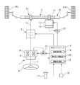
- FIG. 1 is a system diagram illustrating a vehicle steering system according to a first embodiment.
- 3 is a control block diagram of a turning control unit 19.
- FIG. 3 is a control block diagram of a steering reaction force control unit 20.
- FIG. 4 is a control block diagram of a disturbance suppression command turning angle calculation unit 32.
- FIG. 6 is a control block diagram of a repulsive force calculation unit 37 according to a yaw angle. It is a control block diagram of the repulsive force calculation unit 38 according to the lateral position. It is a figure which shows the control area
- FIG. 6 It is a time chart which shows a yaw angle change when the vehicle which is driving
- 6 is a time chart showing yaw angle change and lateral position change when lateral position F / B control is not performed when a vehicle traveling on a straight road on a highway receives continuous lateral wind.
- 6 is a time chart showing a yaw angle change and a lateral position change when lateral position F / B control is performed when a vehicle traveling on a straight road on a highway receives continuous lateral wind.
- 4 is a control block diagram of a lateral force offset unit 34.
- FIG. 6 is a characteristic diagram showing a relationship between a steering angle of a steering wheel and a steering torque of a driver. By offsetting the steering reaction force characteristic representing the steering reaction torque according to the self-aligning torque in the same direction as the self-aligning torque, the characteristic indicating the relationship between the steering angle of the steering wheel and the steering torque of the driver has changed. It is a figure which shows a state.
- 4 is a control block diagram of a steering reaction force torque offset unit 36.
- FIG. FIG. 5 is a control block diagram of a reaction force calculation unit 39 corresponding to a departure allowance time.
- FIG. 6 is a characteristic diagram showing a relationship between a steering angle of a steering wheel and a steering torque of a driver. The relationship between the steering angle of the steering wheel and the steering torque of the driver is shown by offsetting the steering reaction force characteristic representing the steering reaction force torque according to the self-aligning torque in the direction in which the absolute value of the steering reaction force torque increases. It is a figure which shows the state from which the characteristic changed.
- FIG. 5 is a system diagram showing a vehicle steering system according to a second embodiment.
- 4 is a control block diagram of the assist torque control unit 28.
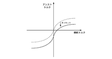
- FIG. 4 is a control block diagram of an assist torque offset unit 42.
- FIG. It is a figure which shows the state which the assist torque characteristic showing the assist torque according to a steering torque offset in the direction in which the absolute value of an assist torque becomes small.
- Steering part 2 Steering part 3 Backup clutch 4 SBW controller 5FL, 5FR Front left and right wheels 6 Steering wheel 7 Column shaft 8 Reaction force motor 9 Steering angle sensor 11 Pinion shaft 12 Steering gear 13 Steering motor 14 Steering angle sensor 15 Rack gear 16 racks 17 Camera 18 Vehicle speed sensor 19 Steering control unit 19a Adder 20 Steering reaction force controller 20a subtractor 20b adder 20c adder 21 Video processor 22 Current driver 23 Current driver 24 Navigation system 25 EPS controller 26 Torque sensor 27 Power steering motor 28 Assist torque control unit 28a subtractor 29 Current driver 31 Command turning angle calculator 32 Disturbance suppression command turning angle calculator 32a Yaw angle calculator 32b Curvature calculator 32c Horizontal position calculator 32d adder 32e Target yaw moment calculator 32f Target yaw acceleration calculator 32g target yaw rate calculator 32h Command turning angle calculator 32i limiter processor 33 Lateral force calculator 34 Lateral force offset 34a Curvature calculator 34b Upper / lower limiter 34c SAT gain calculator 34d multiplier
- FIG. 1 is a system diagram illustrating a vehicle steering system according to the first embodiment.
- the steering device according to the first embodiment mainly includes a steering unit 1, a steering unit 2, a backup clutch 3, and an SBW controller 4, a steering unit 1 that receives a steering input from a driver, and left and right front wheels (steered wheels) 5FL, 5FR.
- a steer-by-wire (SBW) system in which the steering unit 2 that steers the vehicle is mechanically separated is employed.
- the steering unit 1 includes a steering wheel 6, a column shaft 7, a reaction force motor 8, and a steering angle sensor 9.
- the column shaft 7 rotates integrally with the steering wheel 6.
- the reaction force motor 8 is, for example, a brushless motor, the output shaft of which is a coaxial motor coaxial with the column shaft 7, and outputs a steering reaction force torque to the column shaft 7 in response to a command from the SBW controller 4.
- the steering angle sensor 9 detects the absolute rotation angle of the column shaft 7, that is, the steering angle of the steering wheel 6.
- the steered portion 2 includes a pinion shaft 11, a steering gear 12, a steered motor 13, and a steered angle sensor 14.
- the steering gear 12 is a rack and pinion type steering gear, and steers the front wheels 5L and 5R according to the rotation of the pinion shaft 11.
- the steered motor 13 is, for example, a brushless motor, whose output shaft is connected to the rack gear 15 via a reduction gear (not shown), and steers the front wheels 5 to the rack 16 in response to a command from the SBW controller 4.
- the steering torque is output.
- the turning angle sensor 14 detects the absolute rotation angle of the turning motor 13.
- the steered angle of the front wheels 5 can be detected from the rotational angle of the steered motor 13.
- the backup clutch 3 is provided between the column shaft 7 of the steering unit 1 and the pinion shaft 11 of the steering unit 2, and mechanically separates the steering unit 1 and the steering unit 2 by release, and the steering unit 1 by fastening. And the steering unit 2 are mechanically connected.
- the SBW controller 4 is input with the image of the traveling road ahead of the vehicle photographed by the camera 17 and the vehicle speed (vehicle speed) detected by the vehicle speed sensor 18.
- the SBW controller 4 includes a steering control unit 19 that controls the steering angles of the front wheels 5FL and 5FR, a steering reaction force control unit 20 that controls a steering reaction force torque applied to the column shaft 7, and a video processing unit 21.
- the turning control unit 19 generates a command turning angle based on each input information, and outputs the generated command turning angle to the current driver 22.
- the current driver 22 controls the command current to the steered motor 13 by angle feedback that matches the actual steered angle detected by the steered angle sensor 14 with the commanded steered angle.
- the steering reaction force control unit 20 generates a command steering reaction force torque based on each input information, and outputs the generated command steering reaction force torque to the current driver 23.
- the current driver 23 controls the command current to the reaction force motor 8 by torque feedback that matches the actual steering reaction force torque estimated from the current value of the reaction force motor 8 with the command steering reaction force torque.
- the video processing unit 21 recognizes the white lines (traveling line dividing lines) on the left and right of the traveling lane by image processing such as edge extraction from the image of the traveling path ahead of the host vehicle taken by the camera 17.
- the SBW controller 4 engages the backup clutch 3 to mechanically connect the steering unit 1 and the steered unit 2 to move the rack 16 in the axial direction by steering the steering wheel 6. Make it possible.
- control equivalent to an electric power steering system that assists the steering force of the driver by the assist torque of the steering motor 13 may be performed.
- SBW system a redundant system including a plurality of sensors, controllers, and motors may be used. Further, the steering control unit 19 and the steering reaction force control unit 20 may be separated.
- Stability control performs two feedback (F / B) controls for the purpose of improving vehicle stability against disturbances (crosswind, road surface unevenness, dredging, road surface cant, etc.).
- F / B two feedback
- the steering angle is corrected according to the yaw angle, which is the angle between the white line and the direction of travel of the vehicle, and the yaw angle generated by the disturbance is reduced.
- Lateral position F / B control The steering angle is corrected according to the distance to the white line (lateral position), and the lateral position change, which is the integrated value of the yaw angle caused by the disturbance, is reduced.
- the corrected steering reduction control performs three reaction force offset controls for the purpose of improving the stability of the vehicle with respect to the driver's steering input.
- Reaction force offset control according to the lateral position The steering reaction force characteristic according to the self-aligning torque is offset according to the lateral position in the direction in which the absolute value of the steering reaction force increases, and the driver crosses the steering angle neutral position. It is possible to prevent the sign of the steering torque from being reversed when corrective steering is performed.
- Reaction force offset control according to the deviation margin time Offset the steering reaction force characteristic according to the self-aligning torque in the direction in which the absolute value of the steering reaction force increases according to the deviation margin time (time to reach the white line).
- FIG. 2 is a control block diagram of the steering control unit 19.
- the SBW command turning angle calculation unit 31 calculates the SBW command turning angle based on the steering angle and the vehicle speed.
- the disturbance suppression command turning angle calculation unit 32 calculates a disturbance suppression command turning angle for correcting the SBW command turning angle in the stability control based on the vehicle speed and the white line information. Details of the disturbance suppression command turning angle calculation unit 32 will be described later.
- the adder 19a outputs a value obtained by adding the SBW command turning angle and the disturbance suppression command turning angle to the current driver 22 as a final command turning angle.
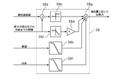
- FIG. 3 is a control block diagram of the steering reaction force control unit 20.
- the lateral force calculation unit 33 refers to a steering angle-lateral force conversion map that represents the relationship between the steering angle for each vehicle speed and the tire lateral force in a conventional steering device that has been obtained in advance through experiments or the like based on the steering angle and the vehicle speed. To calculate the tire lateral force.
- the larger the steering angle the greater the tire lateral force, and when the steering angle is small, the amount of change in the tire lateral force relative to the amount of change in the steering angle is greater than when the steering angle is large.
- the tire has a characteristic that the tire lateral force decreases as the value increases.
- the lateral force offset unit 34 calculates a lateral force offset amount for offsetting the steering reaction force characteristic in the reaction force offset control according to the curvature based on the vehicle speed and the white line information. Details of the lateral force offset unit 34 will be described later.
- the subtractor 20a subtracts the lateral force offset amount from the tire lateral force.
- the SAT calculation unit 35 is a lateral force that represents the relationship between the tire lateral force and the steering reaction force torque in the conventional steering system, which is obtained in advance through experiments or the like based on the vehicle speed and the tire lateral force after offset based on the lateral force offset amount.
- the steering reaction force torque generated by the tire lateral force is calculated with reference to the steering reaction force torque conversion map.
- the tire lateral force-steering reaction torque conversion map shows that the larger the tire lateral force is, the larger the steering reaction torque becomes.
- the amount of change in the steering reaction torque with respect to the amount of change in the tire lateral force is larger than when the tire lateral force is large.
- the steering reaction torque decreases as the vehicle speed increases.
- This characteristic simulates the reaction force generated in the steering wheel by the self-aligning torque in which the wheel generated by the road surface reaction force returns to the straight traveling state in the conventional steering device.
- the adder 20b adds the steering reaction force torque and the steering reaction force torque component (spring term, viscosity term, inertia term) corresponding to the steering characteristics.
- the spring term is a component proportional to the steering angle, and is calculated by multiplying the steering angle by a predetermined gain.
- the viscosity term is a component proportional to the steering angular velocity, and is calculated by multiplying the steering angular velocity by a predetermined gain.
- the inertia term is a component proportional to the steering angular acceleration, and is calculated by multiplying the steering angular acceleration by a predetermined gain.
- the steering reaction force torque offset unit 36 is a steering reaction force torque for offsetting the steering reaction force characteristic in the reaction force offset control according to the lateral position or the deviation margin time based on the vehicle speed and the image of the traveling road ahead of the host vehicle. Calculate the offset amount. Details of the steering reaction torque offset unit 36 will be described later.
- the reaction force offset control suppressing unit 43 includes a counter 43a and a steering reaction force torque offset amount limiting unit 43b.
- the steering reaction force torque offset amount limiting unit 43b starts the reaction force offset control suppression process. In the reaction force offset control suppression process, the steering reaction force torque offset amount is limited.
- the adder 20c outputs a value obtained by adding the steering reaction force torque after adding the steering reaction force torque component corresponding to the steering characteristics and the steering torque offset amount to the current driver 23 as a final command steering reaction force torque. .
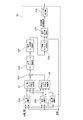
- FIG. 4 is a control block diagram of the disturbance suppression command turning angle calculation unit 32.
- the yaw angle calculator 32a calculates a yaw angle that is an angle formed by the white line at the forward gazing point and the traveling direction of the host vehicle.
- the yaw angle at the forward gazing point is an angle formed by the white line after a predetermined time (for example, 0.5 seconds) and the traveling direction of the vehicle.
- the curvature calculation unit 32b calculates the curvature of the white line at the forward gazing point.
- the lateral position calculation unit 32c calculates the distance to the white line at the front gazing point. Based on the yaw angle, the curvature, and the vehicle speed, the repulsive force calculation unit 37 corresponding to the yaw angle calculates the vehicle repulsive force for reducing the yaw angle generated by the disturbance in the yaw angle F / B control. Details of the repulsive force calculation unit 37 according to the yaw angle will be described later.
- the repulsive force calculation unit 38 according to the lateral position is used to reduce lateral position changes caused by disturbances in lateral position F / B control. Calculate the repulsive force of the vehicle. Details of the repulsive force calculation unit 38 according to the lateral position will be described later.
- the adder 32d adds the repulsive force according to the yaw angle and the repulsive force according to the lateral position, and calculates the lateral repulsive force.
- the target yaw moment calculator 32e calculates a target yaw moment based on the lateral repulsive force, the wheel base (distance between the axles), the rear wheel axle weight, and the front wheel axle weight. Specifically, a value obtained by multiplying the lateral repulsive force by the ratio of the rear wheel axle weight to the vehicle weight (front wheel axle weight + rear wheel axle weight) and the wheel base is set as the target yaw moment.
- the target yaw acceleration calculation unit 32f multiplies the target yaw moment by the yaw inertia moment coefficient to calculate the target yaw acceleration.
- the target yaw rate calculation unit 32g calculates the target yaw rate by multiplying the target yaw acceleration by the vehicle head time.
- the command turning angle calculation unit 32h calculates a disturbance suppression command turning angle ⁇ st * with reference to the following formula based on the target yaw rate ⁇ * , the wheel base WHEEL_BASE, the vehicle speed V, and the vehicle characteristic speed vCh.
- the vehicle characteristic speed V ch is a parameter in the known “Ackermann equation” and represents the self-steering characteristic of the vehicle.
- ⁇ st * ( ⁇ * ⁇ WHEEL_BASE ⁇ (1+ (V / vCh) 2 ) ⁇ 180) / (V ⁇ M_PI) M_PI is a predetermined coefficient.
- the limiter processing unit 32i limits the maximum value of the disturbance suppression command turning angle ⁇ st * and the upper limit of the change rate.
- the maximum value is in a play angle range (for example, 3 ° to the left and right) of the steering wheel 6 near the neutral position in a conventional steering device (the steering unit and the steering unit are mechanically connected).
- the turning angle range of the front wheels 5FL and 5FR corresponding to the range of play at that time (for example, right and left 0.2 °).
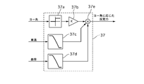
- FIG. 5 is a control block diagram of the repulsive force calculation unit 37 according to the yaw angle.
- the upper / lower limiter 37a performs upper / lower limiter processing on the yaw angle.
- the upper / lower limiter is greater than or equal to a predetermined value capable of suppressing disturbance, and A value that is less than a value that causes the vehicle to vibrate and a value that is generated by the steering of the driver (for example, 1 °), and 0 if the yaw angle is negative.
- the yaw angle F / B gain multiplication unit 37b multiplies the yaw angle after the limiter process by the yaw angle F / B gain.
- the yaw angle F / B gain is equal to or greater than a predetermined value that can ensure responsiveness while avoiding insufficient control amount, and less than the value at which the vehicle vibrates and the driver feels the neutral deviation between the steering angle and the turning angle.
- the vehicle speed correction gain multiplication unit 37c multiplies the vehicle speed by the vehicle speed correction gain.
- the vehicle speed correction gain has a maximum value in the range of 0 to 70 km / h, a gradual decrease in the range of 70 to 130 km / h, and a minimum value (0) in the range of 130 km / h or higher.
- the curvature correction gain multiplication unit 37d multiplies the curvature by the curvature correction gain.
- the curvature correction gain has a characteristic that decreases as the curvature increases, and an upper limit and a lower limit (0) are set.
- the multiplier 37e multiplies the outputs of the yaw angle F / B gain multiplication unit 37b, the vehicle speed correction gain multiplication unit 37c, and the curvature correction gain multiplication unit 37d to obtain a repulsive force according to the yaw angle.
- FIG. 6 is a control block diagram of the repulsive force calculation unit 38 according to the lateral position.
- the subtractor 38a obtains the lateral position deviation by subtracting the distance from the preset lateral position threshold (for example, 90 cm) to the white line at the front gazing point.
- the upper / lower limiter 38b performs upper / lower limiter processing on the lateral position deviation.
- the upper / lower limiter takes a predetermined positive value when the lateral position deviation is a positive value, and is 0 when the lateral position deviation is a negative value.
- the distance correction gain multiplication unit 38c multiplies the distance to the white line at the front gaze point by the distance correction gain.
- the distance correction gain takes a maximum value when the distance to the white line is equal to or smaller than a predetermined value, and when the distance exceeds the predetermined value, the distance correction gain has a characteristic that becomes smaller as the distance becomes longer, and a lower limit is set.
- the horizontal position F / B gain multiplication unit 38d multiplies the distance to the white line corrected by the distance correction gain multiplication unit 38c by the horizontal position F / B gain.
- the lateral position F / B gain is set to a value that is equal to or greater than a predetermined value that can ensure responsiveness while avoiding a shortage of control amount, and that is less than a value that makes the vehicle vibrate and a value that the driver feels neutral deviation.
- a value smaller than the yaw angle F / B gain of the B gain calculation unit 37b is set.
- the vehicle speed correction gain multiplication unit 38e multiplies the vehicle speed by the vehicle speed correction gain.
- the vehicle speed correction gain has a maximum value in the range of 0 to 70 km / h, a gradual decrease in the range of 70 to 130 km / h, and a minimum value (0) in the range of 130 km / h or higher.
- the curvature correction gain multiplication unit 38f multiplies the curvature by the curvature correction gain.
- the curvature correction gain has a characteristic that decreases as the curvature increases, and an upper limit and a lower limit (0) are set.
- the multiplier 38g multiplies each output of the lateral position F / B gain multiplication unit 38d, the vehicle speed correction gain multiplication unit 38e, and the curvature correction gain multiplication unit 38f to obtain a repulsive force according to the lateral position.
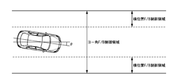
- the yaw angle F / B control for reducing the yaw angle caused by the disturbance and the lateral position F / B control for reducing the lateral position change that is an integral value of the yaw angle caused by the disturbance.
- the yaw angle F / B control is performed regardless of the lateral position when the yaw angle occurs.
- the lateral position F / B control is performed when the distance to the white line is equal to or less than the predetermined lateral position threshold (90 cm). carry out. That is, the vicinity of the center of the traveling lane is a dead zone for lateral position F / B control.
- the control area of both F / B controls is shown in FIG. ⁇ is the yaw angle.
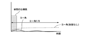
- FIG. 8 is a time chart showing a change in yaw angle when a vehicle traveling on a straight road on a highway receives a single crosswind, and it is assumed that the vehicle is traveling near the center of the traveling lane.
- the yaw angle F / B control calculates the repulsive force according to the yaw angle, finds the disturbance suppression command turning angle to obtain the repulsive force, The SBW command turning angle based on the steering angle and the vehicle speed is corrected.
- the yaw angle is zero because the direction of the white line and the traveling direction of the vehicle coincide with each other, particularly on a straight road.
- the generated yaw angle is considered to be due to disturbance, and by reducing the yaw angle, the stability of the vehicle against disturbance can be improved particularly during straight running.
- the driver's correction steering amount can be reduced.
- 5R can be controlled independently of each other, and the command turning angle is obtained by adding the SBW command turning angle according to the steering angle and the vehicle speed and the disturbance suppression command turning angle according to the yaw angle. Based on this, the steering angle of the front wheels 5L, 5R is controlled, while the tire lateral force is estimated based on the steering angle and the vehicle speed, and the steering reaction force is determined based on the commanded steering reaction force according to the estimated tire lateral force and the vehicle speed. Control power. That is, since the turning angle corresponding to the disturbance suppression is directly given to the front wheels 5L and 5R, it is not necessary to provide a steering reaction force component that prompts the steering for disturbance suppression.
- the fluctuation of the tire lateral force caused by the steering for suppressing the disturbance is not reflected in the steering reaction force, so the driver feels uncomfortable. Can be reduced.
- a tire lateral force is estimated from a rack axial force and a turning angle detected by a sensor, and a steering reaction force corresponding to the estimated tire lateral force is applied. For this reason, the fluctuation of the tire lateral force generated by the steering for suppressing the disturbance is always reflected in the steering reaction force, which makes the driver feel uncomfortable.
- the uncomfortable feeling given to the driver can be reduced.
- the disturbance suppression command turning angle is changed to conventional.
- the steering wheel 6 is in the play angle range near the steering angle neutral position (left and right 3 °)
- the generation of the yaw angle due to disturbance is more conspicuous when traveling straight than when turning, and the steering angle is located near the steering angle neutral position when traveling straight.
- the correction of the turning angle by the yaw angle F / B control is almost always performed near the steering angle neutral position, so the steering angle and the turning angle associated with the provision of the disturbance suppression command turning angle By suppressing the amount of neutral deviation within the range of steering play, it is possible to suppress a sense of incongruity associated with neutral deviation.
- the disturbance suppression command turning angle is limited to a range of 0.2 ° to the left and right, the driver can change the traveling direction of the vehicle to a desired direction by the steering input even during the stability control.
- the amount of correction of the turning angle based on the disturbance suppression command turning angle is very small with respect to the amount of change in the turning angle caused by the driver's steering input. Can be realized.
- lane departure prevention control that gives the vehicle a yaw moment that avoids departure when a vehicle traveling lane departure tendency is detected, or the vehicle travels near the center of the traveling lane.
- Lane keeping control for imparting a yaw moment to a vehicle is known.
- the lane departure prevention control is a control having a threshold for control intervention, and the control does not operate in the vicinity of the center of the traveling lane, so the stability of the vehicle against disturbance cannot be ensured. Further, even when the driver wants to bring the vehicle to the end of the traveling lane, control intervention is performed according to the threshold value, which causes trouble for the driver.
- the control has a target position (target line), and although the stability of the vehicle against disturbance can be ensured, a line deviating from the target line cannot be driven.
- the control is canceled by determining that the steering wheel is released, so the driver must always grip the steering wheel with a certain force or more, and the driver's steering load is reduced. large.
- the yaw angle F / B control of the first embodiment does not have a threshold value for control intervention, it is possible to always ensure stability against disturbance by seamless control.
- the driver since it does not have a target position, the driver can drive the vehicle along a favorite line. In addition, even when the steering wheel 6 is held lightly, the control is not released, and the steering load on the driver can be reduced.
- FIG. 9 is a time chart showing the yaw angle change and the lateral position change when the lateral position F / B control is not performed when the vehicle traveling on the straight road of the expressway receives continuous lateral wind. Is driving near the center of the driving lane.
- the yaw angle F / B control reduces the yaw angle, and when the yaw angle is zero, the turning angle is not corrected, so the lateral position change, which is the integrated value of the yaw angle caused by the disturbance, is directly detected.
- the yaw angle multiplied by the yaw angle F / B gain is limited to the upper limit (1 °) or less by the upper / lower limiter 37a.
- the repulsive force according to the yaw angle is a repulsive force corresponding to a yaw angle smaller than the actual yaw angle. From this point, the lateral flow of the vehicle can be effectively suppressed only by the yaw angle F / B control. Proves difficult.
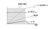
- FIG. 10 is a time chart showing changes in yaw angle and lateral position when lateral position F / B control is performed when a vehicle traveling on a straight road on a highway receives continuous lateral wind.
- position F / B control when the vehicle running near the center of the lane is subjected to continuous crosswinds and flows laterally, and the distance to the white line is less than the lateral position threshold, the lateral position changes ( ⁇ yaw angle integral value). The corresponding repulsive force is calculated.
- the disturbance suppression command turning angle calculation unit 32 calculates the disturbance suppression command turning angle based on the lateral repulsive force that is the sum of the repulsive force according to the lateral position and the repulsive force according to the yaw angle. Correct the corners. That is, in the lateral position F / B control, the SBW command turning angle is corrected by the disturbance suppression command turning angle according to the lateral position, so it is possible to directly reduce the lateral position change due to steady disturbance. Yes, the lateral flow of the vehicle can be suppressed. In other words, the travel position of the vehicle that performs the yaw angle F / B control can be returned to the vicinity of the center of the travel lane, which is the dead zone of the lateral position F / B control.
- the stability control of the first embodiment reduces the yaw angle change due to the transient disturbance by the yaw angle F / B control, and the yaw angle integral value (lateral position change) due to the steady disturbance is changed to the horizontal position.
- Reduction by F / B control can improve both vehicle stability against transient and steady disturbances.
- the stability control of the first embodiment is such that the driver is not aware of the vehicle behavior caused by the control (giving the disturbance suppression command turning angle) and does not disturb the vehicle behavior change caused by the driver's steering. This is possible without limiting the driver to be aware that the stability control is being performed because the change in the self-aligning torque caused by the control is not reflected in the steering reaction force.
- the lateral position F / B control the lateral position F / B gain for obtaining the repulsive force according to the lateral position is set to a value smaller than the yaw angle F / B gain.
- the yaw angle F / B control is required to converge the yaw angle before the driver feels a change in yaw angle due to a transient disturbance.
- B control is required to stop increasing the lateral position change, and it takes time for the lateral position to change due to the accumulation of the yaw angle integral value. Is not necessary.
- the control amount fluctuates greatly depending on the magnitude of the disturbance, giving the driver a sense of incongruity.
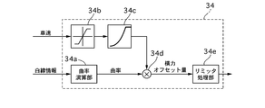
- FIG. 11 is a control block diagram of the lateral force offset unit 34.
- the curvature calculation unit 34a calculates the curvature of the white line at the forward gazing point. As the white line, either the left or right white line may be used.
- the upper / lower limiter 34b performs upper / lower limiter processing on the vehicle speed.
- the SAT gain calculation unit 34c calculates the SAT gain according to the vehicle speed based on the vehicle speed after the limiter process.
- the SAT gain has a characteristic that increases as the vehicle speed increases, and an upper limit is set.
- the multiplier 34d obtains the lateral force offset amount by multiplying the SAT gain by the curvature.
- the limiter processing unit 34e limits the maximum value of the lateral force offset amount and the upper limit of the change rate. For example, the maximum value is 1,000 N, and the upper limit of the change rate is 600 N / s.
- reaction force offset control according to curvature obtains a larger lateral force offset amount as the curvature of the white line is larger, and subtracts it from the tire lateral force.
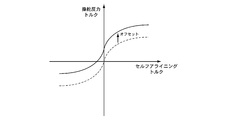
- the steering reaction force torque corresponding to the tire lateral force calculated by the SAT calculation unit 35 that is, the steering reaction force characteristic indicating the steering reaction force torque corresponding to the self-aligning torque, is shown in FIG.
- the self-aligning torque is offset in the same sign direction. Note that FIG. 12 shows the case of the right curve, and the case of the left curve is offset in the opposite direction to FIG.
- a steering reaction force characteristic that simulates the steering reaction force according to the self-aligning torque in the conventional steering device is set, and the steering reaction force A steering reaction force is applied to the steering wheel based on the characteristics.
- the relationship between the steering angle of the steering wheel and the steering torque of the driver is a characteristic A as shown in FIG. That is, the larger the absolute value of the steering angle, the larger the absolute value of the steering torque.
- the absolute value of the steering angle is small, the amount of change of the steering torque with respect to the amount of change of the steering angle becomes larger than when the absolute value of the steering angle is large.
- the steering reaction force characteristic representing the steering reaction force torque corresponding to the self-aligning torque becomes the same sign direction as the self-aligning torque as the curvature of the white line is larger.
- the characteristic representing the relationship between the steering angle and the steering torque is offset in the same sign direction as the steering angle, and changes from characteristic A to characteristic B.
- the driver reduces the fixed steering torque to T 4, the reduction amount [Delta] T 3-4 of steering holding torque Figure
- the decrease amount ⁇ 1-4 of the steering angle is smaller than the decrease amount ⁇ 1-2 of the prior art.
- the greater the curvature of the curve the smaller the fluctuation of the steering angle with respect to the change in the steering torque and the lower the sensitivity of the vehicle to the steering torque, so that the behavior change of the vehicle becomes gradual and the course correction by the driver is facilitated. be able to.
- the steering torque T 3 ( ⁇ T 1 ) for maintaining the steering angle ⁇ 1 can be made smaller than that of the prior art, the driver's steering burden during turning can be reduced.
- FIG. 15 is a control block diagram of the steering reaction force torque offset unit 36.
- the yaw angle calculator 36a calculates the yaw angle at the forward gazing point. By calculating the yaw angle based on the image of the travel path taken by the camera 17, the yaw angle can be detected easily and with high accuracy.
- As the white line either the left or right white line may be used.
- the horizontal position calculation unit 36b calculates a horizontal position with respect to the left and right white lines at the forward gazing point and a horizontal position with respect to the left and right white lines at the current position.
- the horizontal position calculation unit 36b switches the horizontal position with respect to the left and right white lines at the current position. That is, the horizontal position with respect to the left white line before reaching the white line is set as the horizontal position with respect to the right white line after reaching the white line, and the horizontal position with respect to the right white line before reaching the white line is set as the horizontal position with respect to the left white line after reaching the white line.
- the value W 2 / W 1 obtained by dividing the lane width W 2 of the lane after the lane change by the lane width W 1 of the lane before the lane change is replaced.
- the horizontal position is corrected by multiplying the horizontal position.
- the lane width information of each traveling lane is acquired from the navigation system 24.
- the reaction force calculation unit 39 corresponding to the departure allowance time calculates the reaction force corresponding to the departure allowance time based on the vehicle speed, the yaw angle, and the lateral position with respect to the left and right white lines at the front gazing point. Details of the reaction force calculation unit 39 according to the departure allowance time will be described later.
- the reaction force calculation unit 40 according to the lateral position calculates a reaction force according to the lateral position based on the lateral position with respect to the left and right white lines at the current position. Details of the reaction force calculation unit 40 according to the lateral position will be described later.
- the reaction force selection unit 36c selects, as the steering reaction force torque offset amount, the larger absolute value among the reaction force according to the departure allowance time and the reaction force according to the lateral position.
- the limiter processing unit 36d limits the maximum value of the steering reaction force torque offset amount and the upper limit of the change rate. For example, the maximum value is 2 Nm, and the upper limit of the change rate is 10 Nm / s.
- FIG. 16 is a control block diagram of the reaction force calculation unit 39 according to the departure allowance time.
- the multiplier 39a obtains the lateral speed of the vehicle by multiplying the yaw angle by the vehicle speed.
- the divider 39b divides the lateral position with respect to the left white line at the forward gazing point by the lateral speed to obtain a deviation margin time with respect to the left white line.
- the divider 39c divides the lateral position with respect to the right white line at the forward gazing point by the lateral speed to obtain a deviation margin time with respect to the right white line.
- the deviation margin time selection unit 39d selects the shorter of the deviation margin times for the left and right white lines as the deviation margin time.
- the reaction force calculator 39e according to the departure allowance time calculates a reaction force according to the departure allowance time based on the departure allowance time.
- the reaction force according to the deviation margin time is inversely proportional to the deviation margin time (proportional to the reciprocal of the deviation margin time), and has a characteristic of almost zero after 3 seconds.
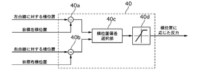
- FIG. 17 is a control block diagram of the reaction force calculation unit 40 according to the lateral position.
- the subtractor 40a obtains a lateral position deviation with respect to the left lane by subtracting the lateral position with respect to the left lane from a preset target left lateral position (for example, 90 cm).
- the subtractor 40b subtracts the lateral position with respect to the right lane from a preset target right lateral position (for example, 90 cm) to obtain a lateral position deviation with respect to the right lane.
- the lateral position deviation selection unit 40c selects the larger one of the lateral position deviations with respect to the left and right lanes as the lateral position deviation.
- the reaction force calculation unit 40d according to the lateral position deviation calculates a reaction force according to the lateral position based on the lateral position deviation.
- the reaction force according to the lateral position has a characteristic that increases as the lateral position deviation increases, and an upper limit is set.
- reaction force offset control action according to lateral position In the reaction force offset control according to the lateral position, the reaction force according to the lateral position is added to the steering reaction force torque as a steering reaction force torque offset amount.
- the steering reaction force characteristic representing the steering reaction force torque corresponding to the self-aligning torque is offset in a direction in which the absolute value of the steering reaction force torque increases as the distance to the white line decreases, as shown in FIG.
- the FIG. 18 shows a case where the vehicle is close to the right lane. When the vehicle is close to the left lane, the vehicle is offset in the opposite direction to FIG.
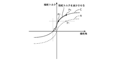
- the driving position of the vehicle is shifted to the right side due to the driver's unexpected increase in the right direction, and then the driver returns the driving position to the vicinity of the center of the driving lane by correction steering.
- the steering angle and steering torque when the driver performs an unexpected operation are set as the position of point P 1 on the characteristic A in FIG.
- the characteristic A is a characteristic representing the relationship between the steering angle and the steering torque when the steering reaction force characteristic simulating a conventional steering device is set, as in FIG.
- the steering reaction force torque according to the self-aligning torque is increased in the direction in which the absolute value of the steering reaction force torque increases as the distance to the white line is shorter.
- the characteristic representing the relationship between the steering angle and the steering torque by the offset is offset from the characteristic A as the distance to the white line becomes shorter as the absolute value of the steering torque is increased as shown in FIG. Changes continuously to C.
- the steering wheel 6 is gradually returned to the steering angle neutral position (point P 1 ⁇ point P 2 ), It is possible to prevent the vehicle travel position from shifting to the right side due to the driver's unexpected increase operation.
- the steering angle and the steering torque move from the point P 1 to the point P 3 .
- the steering torque neutral position is offset from the steering angle neutral position to the additional side, so the steering torque neutral position is increased when the steering angle is increased from the steering angle neutral position.
- the sign of the steering torque is not reversed until the position is reached. Therefore, the driver can control the turning angle of the front wheels 5L and 5R only by reducing the steering torque and stopping the rotation of the steering wheel 6 when the steering wheel 6 reaches the target angle.
- the reaction force offset control according to the lateral position of the first embodiment can facilitate the driver's correction steering because the direction in which the driver controls the force is difficult to switch. As a result, the travel position of the vehicle is less likely to overshoot, and the correction steering amount can be reduced.
- the offset amount is increased as the distance to the white line is shorter. Therefore, the steering torque neutral position is the steering angle neutral position as the distance to the white line is shorter. Is offset further away from When the driver performs corrective steering to return the vehicle travel position to the vicinity of the center of the travel lane, the closer the white line is, the greater the amount of additional operation from the steering angle neutral position is required. At this time, if the offset amount of the steering torque neutral position with respect to the steering angle neutral position is small, the steering torque may exceed the neutral position and the sign of the steering torque may be reversed before the steering wheel reaches the target angle. Therefore, it is possible to suppress the steering torque from exceeding the neutral position by increasing the offset amount as the distance to the white line is shorter.
- the lateral position calculation unit 36b switches the lateral position with respect to the left and right white lines at the current position when the host vehicle reaches the white line.
- the host vehicle is more likely to return to the vicinity of the center of the travel lane by increasing the steering reaction force as the host vehicle is further away from the vicinity of the center of the travel lane.
- the yaw angle integral value (lateral position change) is regarded as a disturbance, and the steering reaction force is controlled so as to guide the vehicle in a direction in which the yaw angle integral value disappears. For this reason, when a lane change is performed, it is necessary to reset the yaw angle integral value.
- the steering reaction force for returning the vehicle to the vicinity of the center of the traveling lane before the lane change continues to act even after the lane change, and the driver's operation is hindered. Note that the vehicle cannot be guided near the center of the travel lane after the lane change by simply setting the integral value to zero.
- the vehicle when the vehicle reaches the white line, it can be regarded as a driver's intentional operation. In this case, the lateral position with respect to the left and right white lines at the current position is switched. In order to guide the vehicle to the center of the lane after the lane change by switching the position where the vehicle is guided from the center of the lane before the lane change to the center of the lane after the lane change.
- the steering reaction force can be generated.
- reaction force offset control action according to deviation margin time In the reaction force offset control according to the departure allowance time, the reaction force according to the departure allowance time is added to the steering reaction force torque as the steering reaction force torque offset amount.
- the steering reaction force characteristic representing the steering reaction force torque corresponding to the self-aligning torque is offset in a direction in which the absolute value of the steering reaction force torque increases as the deviation margin time decreases, as shown in FIG.
- the FIG. 18 shows a case where the vehicle is close to the right lane. When the vehicle is close to the left lane, the vehicle is offset in the opposite direction to FIG.
- the characteristic representing the relationship between the steering angle and the steering torque is offset in the direction in which the absolute value of the steering torque increases as shown in FIG. 20, and from characteristic A to characteristic C as the deviation margin time becomes shorter. And change continuously.
- the steering angle neutral position point P 1 ⁇ point P 2
- the steering angle and the steering torque move from the point P 1 to the point P 3 .
- the steering torque neutral position is offset from the steering angle neutral position to the additional side, so the steering torque neutral position is increased when the steering angle is increased from the steering angle neutral position.
- the sign of the steering torque is not reversed until the position is reached. Therefore, the driver can control the turning angle of the front wheels 5L and 5R only by reducing the steering torque and stopping the rotation of the steering wheel 6 when the steering wheel 6 reaches the target angle. That is, the reaction force offset control according to the departure allowance time according to the first embodiment can facilitate the driver's correction steering because the direction in which the driver controls the force is difficult to switch. As a result, the travel position of the vehicle is less likely to overshoot, and the correction steering amount can be reduced.
- the offset amount is increased as the departure allowance time is shorter. Therefore, the steering torque neutral position is changed from the steering angle neutral position as the departure allowance time is shorter. Offset to a more distant position.
- the driver performs corrective steering to return the vehicle travel position to near the center of the travel lane, the shorter the deviation margin time, the closer to the white line, and the closer to the white line, the greater the amount of operation to increase from the steering angle neutral position.
- the offset amount of the steering torque neutral position with respect to the steering angle neutral position is small, the steering torque may exceed the neutral position and the sign of the steering torque may be reversed before the steering wheel reaches the target angle. Therefore, it is possible to suppress the steering torque from exceeding the neutral position by increasing the offset amount as the distance to the white line is shorter.
- the steering reaction force torque offset unit 36 selects the reaction force corresponding to the deviation margin time and the reaction force corresponding to the lateral position having the larger absolute value as the steering reaction force torque offset amount.
- the adder 20c adds the steering reaction torque offset amount to the steering reaction torque.
- the steering reaction force characteristic is offset in the direction in which the absolute value of the steering reaction force torque is increased in accordance with the departure allowance time or the lateral position.
- the reaction force offset control according to the departure allowance time when the vehicle and the white line are parallel, that is, when the yaw angle is zero, the reaction force according to the departure allowance time is zero.
- reaction force offset control according to the horizontal position
- a reaction force is generated in proportion to the distance to the white line, so a larger reaction force as the distance to the white line becomes shorter. And the vehicle can be easily returned to the vicinity of the center of the traveling lane.
- reaction force offset control according to the lateral position when the vehicle is near the center of the traveling lane, the reaction force according to the lateral position is zero. For this reason, even in the vicinity of the center of the traveling lane, when the yaw angle is large and the vehicle speed is high, it is difficult to increase the steering reaction force with good response while reaching the white line in a short time.
- reaction force offset control according to the departure allowance time a reaction force (reaction force according to the departure allowance time) is generated according to the departure allowance time, and the reaction force has a departure allowance time of 3 seconds.
- the steering reaction force can be increased with good response to suppress lane departure. Therefore, by using the reaction force offset control according to the departure allowance time and the reaction force offset control according to the lateral position, it is possible to effectively deviate from the lane while giving a stable reaction force according to the distance to the white line. Can be suppressed. At this time, the optimum steering reaction force that is always required can be applied by using the reaction force corresponding to the departure allowance time and the reaction force corresponding to the lateral position having the larger absolute value.
- reaction offset control suppression when one side white line is lost In the system that assists the steering continuously during traveling using the left and right white line information of the traveling lane, such as the reaction force offset control according to the lateral position and the departure allowance time in the first embodiment, the left and right white lines are far from the own vehicle. When the white line is lost and information on the other white line cannot be obtained, the control needs to be interrupted. As another method, the method of estimating the position of the white line from the past lane width and continuing the control can be considered, but on the road surface represented by the merging and merging, there is a difference between the actual lane width and the lane width used for estimation. Therefore, it is difficult to accurately estimate the position of the lost white line, which is not a preferable method.
- Example 1 has the following effects.
- Video processor 21 (white line detection means) that detects the left and right white lines of the driving lane and steering in the direction in which the vehicle approaches the white line when the vehicle approaches one of the detected white lines
- Steering reaction force torque offset portion 36 (white line approaching) that calculates a steering reaction force torque offset amount (white line approaching suppression steering reaction force) to be suppressed and increases the steering reaction force torque offset amount as the distance between the vehicle and the white line is closer.
- a suppression steering reaction force calculating means a steering reaction force control section 20 (steering reaction force control means) for controlling a steering reaction force applied to the steering section 1 that receives the steering input of the driver based on the steering reaction force torque offset amount;
- the reaction force offset control suppressing unit 43 that limits the steering reaction force torque offset amount when the increase gradient of the steering reaction force torque offset amount is equal to or less than a predetermined increase gradient. (Restricted hand Stage).
- the reaction force offset control suppression unit 43 limits the steering reaction force torque offset amount when the steering reaction force torque offset amount falls below the previous value. By starting limiting the steering reaction force torque offset amount when the steering reaction force torque offset amount shows a decreasing trend, the vehicle behavior approaches the vehicle behavior expected by the driver, so that the driver can feel less uncomfortable.
- the reaction force offset control suppressing unit 43 prohibits an increase in the steering reaction force torque offset amount and allows a decrease. Thereby, compared with the case where the steering reaction force torque offset amount is maintained, the vehicle behavior approaches the vehicle behavior expected by the driver, so that the uncomfortable feeling given to the driver can be further reduced.
- the reaction force offset control suppressing unit 43 determines that the other of the left and right white lines cannot be detected when the state in which the other of the left and right white lines cannot be detected continues for a predetermined time. As a result, when the loss of the white line is relatively short, such as when the white line can be detected immediately after it becomes undetectable, the reaction force offset control according to the lateral position and the deviation margin time can be continued. Lane departure can be suppressed.
- the steering reaction force control unit 20 adds the steering reaction force torque offset amount to the steering reaction force torque obtained from the predetermined steering reaction force characteristic according to the self-aligning torque acting on the left and right front wheels 5FL, 5FR.
- a steering reaction force is applied to the steering unit 1 based on the command steering reaction force.
- the steering unit 1 is mechanically separated from the steering unit 2 that steers the left and right front wheels 5FL, 5FR, and a curvature calculation unit 34a (curvature detection means) that detects the curvature of the white line, and the detected curvature is And a lateral force offset section 34 (offset amount calculating means) that calculates a larger lateral force offset amount as the larger the steering force, the steering reaction force control section 20 is offset from the self-aligning torque acting on the left and right front wheels 5FL, 5FR.
- the steering reaction force torque is applied to the steering unit 1 based on the commanded steering reaction force obtained from the offset self-aligning torque obtained by subtracting the amount and a predetermined steering reaction force characteristic corresponding to the self-aligning ork.
- the offset unit 36 does not limit the lateral force offset amount even when it is determined that the other of the left and right white lines cannot be detected. Since the curvature can be detected based on either the left or right white line, even if the other of the left and right white lines becomes undetectable, the reaction force offset control according to the curvature is not affected at all. Therefore, by continuing the reaction force offset control according to the curvature, it is possible to realize both the reduction of the driver's steering burden and the ease of course correction during turning.
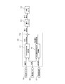
- FIG. 21 is a system diagram illustrating a vehicle steering system according to the second embodiment.
- the steering device according to the second embodiment includes a steering unit 1, a steering unit 2, and an EPS controller 25 as main components.
- the steering unit 1 that receives a driver's steering input and the left and right front wheels (steered wheels) 5FL and 5FR are steered.
- the rudder part 2 is mechanically connected.
- the steering unit 1 includes a steering wheel 6, a column shaft 7, and a torque sensor 26.
- the torque sensor 26 detects the steering torque of the driver input from the steering wheel 6 to the column shaft 7.
- the steered portion 2 includes a pinion shaft 11, a steering gear 12, and a power steering motor 27.
- the pinion shaft 11 is connected to the column shaft 7 via a torsion bar of the torque sensor 26.
- the power steering motor 27 is, for example, a brushless motor, and an output shaft is connected to the rack gear 15 via a reduction gear (not shown), and assists the steering force of the driver to the rack 16 according to a command from the EPS controller 25. Outputs assist torque.
- the EPS controller 25 receives an image of the traveling road in front of the vehicle and the vehicle speed (body speed) detected by the vehicle speed sensor 18 taken by the camera 17.
- the EPS controller 25 includes an assist torque control unit (assist torque control means, controller) 28 and a video processing unit 21.
- the assist torque control unit 28 generates a command assist torque based on each input information, and outputs the generated command assist torque to the current driver 29.
- the current driver 29 controls the command current to the power steering motor 27 by torque feedback that matches the actual assist torque estimated from the current value of the power steering motor 27 with the command assist torque.
- the video processing unit 21 recognizes the white lines (traveling line dividing lines) on the left and right of the traveling lane by image processing such as edge extraction from the image of the traveling path ahead of the host vehicle taken by the camera 17.
- FIG. 22 is a control block diagram of the assist torque control unit 28.
- the assist torque calculator 41 calculates an assist torque based on the steering torque and the vehicle speed with reference to a preset assist torque map.
- the assist torque characteristic in the assist torque map has such a characteristic that it increases as the absolute value of the steering torque increases or the vehicle speed decreases.
- the assist torque offset unit 42 calculates an assist torque offset amount for offsetting the assist torque characteristic in the assist torque offset control according to the lateral position or the deviation margin time based on the vehicle speed and the image of the traveling road ahead of the host vehicle. . Details of the assist torque offset unit 42 will be described later.
- the subtractor 28a outputs a value obtained by subtracting the assist torque offset amount from the assist torque to the current driver 29 as a final command assist torque. [Assist torque offset section]
- FIG. 23 is a control block diagram of the assist torque offset unit 42.
- the reaction force selection unit 42c selects, as the assist torque offset amount, the larger absolute value of the reaction force according to the deviation allowance time and the reaction force according to the lateral position.
- the assist torque offset control suppressing unit 44 includes a counter 44a and an assist torque offset amount limiting unit 44b.
- the assist torque offset amount limiting unit 44b starts the assist torque offset control suppression process.
- the assist torque offset amount is limited. Specifically, when the assist torque offset amount exceeds the previous value, the previous value is output as the assist torque offset amount, and when the assist torque offset amount is less than the previous value, the current value is output.
Abstract
Priority Applications (6)
| Application Number | Priority Date | Filing Date | Title |
|---|---|---|---|
| JP2014539676A JP5994861B2 (ja) | 2012-10-04 | 2013-09-25 | 操舵制御装置 |
| MX2015004136A MX2015004136A (es) | 2012-10-04 | 2013-09-25 | Dispositivo de control de direccion. |
| CN201380052224.0A CN104736416B (zh) | 2012-10-04 | 2013-09-25 | 转轮控制装置 |
| EP13844385.8A EP2905207B1 (fr) | 2012-10-04 | 2013-09-25 | Dispositif de commande de direction |
| US14/428,327 US9623901B2 (en) | 2012-10-04 | 2013-09-25 | Steering control device |
| RU2015116898/11A RU2582517C1 (ru) | 2012-10-04 | 2013-09-25 | Устройство управления рулением |
Applications Claiming Priority (2)
| Application Number | Priority Date | Filing Date | Title |
|---|---|---|---|
| JP2012221785 | 2012-10-04 | ||
| JP2012-221785 | 2012-10-04 |
Publications (1)
| Publication Number | Publication Date |
|---|---|
| WO2014054476A1 true WO2014054476A1 (fr) | 2014-04-10 |
Family
ID=50434804
Family Applications (1)
| Application Number | Title | Priority Date | Filing Date |
|---|---|---|---|
| PCT/JP2013/075801 WO2014054476A1 (fr) | 2012-10-04 | 2013-09-25 | Dispositif de commande de direction |
Country Status (7)
| Country | Link |
|---|---|
| US (1) | US9623901B2 (fr) |
| EP (1) | EP2905207B1 (fr) |
| JP (1) | JP5994861B2 (fr) |
| CN (1) | CN104736416B (fr) |
| MX (1) | MX2015004136A (fr) |
| RU (1) | RU2582517C1 (fr) |
| WO (1) | WO2014054476A1 (fr) |
Cited By (3)
| Publication number | Priority date | Publication date | Assignee | Title |
|---|---|---|---|---|
| CN105501288A (zh) * | 2014-10-10 | 2016-04-20 | 丰田自动车株式会社 | 转向助力控制装置和转向助力控制方法 |
| WO2020026342A1 (fr) * | 2018-07-31 | 2020-02-06 | 三菱電機株式会社 | Système de commande de direction |
| CN111746626A (zh) * | 2019-03-27 | 2020-10-09 | 丰田自动车株式会社 | 车辆的控制装置与控制方法 |
Families Citing this family (15)
| Publication number | Priority date | Publication date | Assignee | Title |
|---|---|---|---|---|
| RU2636636C2 (ru) * | 2012-10-01 | 2017-11-24 | Ниссан Мотор Ко., Лтд. | Устройство управления устойчивостью |
| US10065674B2 (en) * | 2015-11-27 | 2018-09-04 | Jtekt Corporation | Steering control device |
| JP6213904B1 (ja) * | 2016-06-30 | 2017-10-18 | マツダ株式会社 | 車両用挙動制御装置 |
| US10787192B1 (en) | 2017-04-11 | 2020-09-29 | Apple Inc. | Steer-by-wire system with multiple steering actuators |
| KR101981480B1 (ko) * | 2017-12-07 | 2019-05-23 | 현대모비스 주식회사 | 전동식 파워 스티어링 시스템의 제어 장치 및 방법 |
| JP6963490B2 (ja) * | 2017-12-15 | 2021-11-10 | 株式会社デンソー | 車両制御装置 |
| JP6965739B2 (ja) * | 2017-12-27 | 2021-11-10 | 株式会社デンソー | 車両制御装置 |
| DE102018109084A1 (de) * | 2018-04-17 | 2019-10-17 | Thyssenkrupp Ag | Verfahren zur Steuerung eines Steer-by-Wire Lenksystems mit einem Begrenzer zum Erreichen eines Sicherheitsniveaus |
| WO2020130479A1 (fr) * | 2018-12-19 | 2020-06-25 | 주식회사 만도 | Appareil de commande de direction, procédé de commande de direction et dispositif de direction |
| US10843728B2 (en) * | 2019-01-31 | 2020-11-24 | StradVision, Inc. | Method and device for delivering steering intention of autonomous driving module or driver to steering apparatus of subject vehicle more accurately |
| JP7376242B2 (ja) * | 2019-03-19 | 2023-11-08 | 株式会社ジェイテクト | 操舵制御装置 |
| JP2020163989A (ja) * | 2019-03-29 | 2020-10-08 | 株式会社ジェイテクト | 操舵制御装置 |
| JP2020163990A (ja) * | 2019-03-29 | 2020-10-08 | 株式会社ジェイテクト | 操舵制御装置 |
| FR3094317B1 (fr) * | 2019-04-01 | 2021-03-05 | Renault Sas | Module anticipateur, dispositif de contrôle en temps réel de trajectoire et procédé associés |
| JP2022130052A (ja) * | 2021-02-25 | 2022-09-06 | 本田技研工業株式会社 | 車両制御装置及び車両 |
Citations (4)
| Publication number | Priority date | Publication date | Assignee | Title |
|---|---|---|---|---|
| JPH10273062A (ja) * | 1997-03-28 | 1998-10-13 | Toyota Motor Corp | 車両の操舵制御装置 |
| JP2003040132A (ja) * | 2001-07-27 | 2003-02-13 | Mitsubishi Motors Corp | 走行レーン逸脱防止装置 |
| JP2010030504A (ja) * | 2008-07-30 | 2010-02-12 | Nissan Motor Co Ltd | 車両用操舵制御装置及び車両用操舵制御方法 |
| JP2011051570A (ja) | 2009-09-04 | 2011-03-17 | Honda Motor Co Ltd | 車両用接触回避支援装置 |
Family Cites Families (9)
| Publication number | Priority date | Publication date | Assignee | Title |
|---|---|---|---|---|
| JP3585874B2 (ja) | 2001-09-04 | 2004-11-04 | 本田技研工業株式会社 | 車両の走行制御装置 |
| JP4082388B2 (ja) * | 2004-06-01 | 2008-04-30 | トヨタ自動車株式会社 | 走行制御装置 |
| JP4349210B2 (ja) | 2004-06-02 | 2009-10-21 | トヨタ自動車株式会社 | 運転支援装置 |
| JP4867313B2 (ja) | 2004-12-27 | 2012-02-01 | 日産自動車株式会社 | 車線逸脱防止装置 |
| JP4684698B2 (ja) * | 2005-03-22 | 2011-05-18 | 本田技研工業株式会社 | 車両の操舵制御装置 |
| JP5139688B2 (ja) * | 2007-02-06 | 2013-02-06 | 本田技研工業株式会社 | 車両用操舵装置 |
| RU96822U1 (ru) * | 2010-04-20 | 2010-08-20 | Андрей Игоревич Крюков | Система контроля "мертвой зоны" боковых зеркал автомобиля |
| WO2013186903A1 (fr) * | 2012-06-14 | 2013-12-19 | トヨタ自動車株式会社 | Appareil de détection de marquage de séparation de voie de circulation, et système d'aide à la conduite |
| WO2014054475A1 (fr) | 2012-10-04 | 2014-04-10 | 日産自動車株式会社 | Dispositif de commande de direction |
-
2013
- 2013-09-25 CN CN201380052224.0A patent/CN104736416B/zh active Active
- 2013-09-25 MX MX2015004136A patent/MX2015004136A/es unknown
- 2013-09-25 WO PCT/JP2013/075801 patent/WO2014054476A1/fr active Application Filing
- 2013-09-25 US US14/428,327 patent/US9623901B2/en active Active
- 2013-09-25 RU RU2015116898/11A patent/RU2582517C1/ru active
- 2013-09-25 EP EP13844385.8A patent/EP2905207B1/fr active Active
- 2013-09-25 JP JP2014539676A patent/JP5994861B2/ja active Active
Patent Citations (4)
| Publication number | Priority date | Publication date | Assignee | Title |
|---|---|---|---|---|
| JPH10273062A (ja) * | 1997-03-28 | 1998-10-13 | Toyota Motor Corp | 車両の操舵制御装置 |
| JP2003040132A (ja) * | 2001-07-27 | 2003-02-13 | Mitsubishi Motors Corp | 走行レーン逸脱防止装置 |
| JP2010030504A (ja) * | 2008-07-30 | 2010-02-12 | Nissan Motor Co Ltd | 車両用操舵制御装置及び車両用操舵制御方法 |
| JP2011051570A (ja) | 2009-09-04 | 2011-03-17 | Honda Motor Co Ltd | 車両用接触回避支援装置 |
Non-Patent Citations (1)
| Title |
|---|
| See also references of EP2905207A4 |
Cited By (4)
| Publication number | Priority date | Publication date | Assignee | Title |
|---|---|---|---|---|
| CN105501288A (zh) * | 2014-10-10 | 2016-04-20 | 丰田自动车株式会社 | 转向助力控制装置和转向助力控制方法 |
| WO2020026342A1 (fr) * | 2018-07-31 | 2020-02-06 | 三菱電機株式会社 | Système de commande de direction |
| JPWO2020026342A1 (ja) * | 2018-07-31 | 2020-12-17 | 三菱電機株式会社 | 操舵制御装置 |
| CN111746626A (zh) * | 2019-03-27 | 2020-10-09 | 丰田自动车株式会社 | 车辆的控制装置与控制方法 |
Also Published As
| Publication number | Publication date |
|---|---|
| EP2905207B1 (fr) | 2016-12-28 |
| JPWO2014054476A1 (ja) | 2016-08-25 |
| US20150225014A1 (en) | 2015-08-13 |
| US9623901B2 (en) | 2017-04-18 |
| CN104736416A (zh) | 2015-06-24 |
| EP2905207A1 (fr) | 2015-08-12 |
| EP2905207A4 (fr) | 2015-12-09 |
| MX2015004136A (es) | 2015-07-06 |
| JP5994861B2 (ja) | 2016-09-21 |
| CN104736416B (zh) | 2016-08-24 |
| RU2582517C1 (ru) | 2016-04-27 |
Similar Documents
| Publication | Publication Date | Title |
|---|---|---|
| JP5994861B2 (ja) | 操舵制御装置 | |
| JP5794394B2 (ja) | 操舵制御装置 | |
| JP5892255B2 (ja) | スタビリティ制御装置 | |
| JP5794393B2 (ja) | 操舵制御装置 | |
| JP5994860B2 (ja) | 操舵制御装置 | |
| JP6119768B2 (ja) | スタビリティ制御装置 | |
| JP5979239B2 (ja) | 操舵制御装置 | |
| JP6003997B2 (ja) | スタビリティ制御装置 | |
| JP5979249B2 (ja) | 操舵制御装置 | |
| JP5979238B2 (ja) | 操舵制御装置 | |
| WO2014054623A1 (fr) | Dispositif de commande de direction | |
| WO2014208248A1 (fr) | Dispositif de commande de direction | |
| JP5794395B2 (ja) | 操舵制御装置 | |
| JP5971126B2 (ja) | 操舵制御装置 | |
| JP2015009761A (ja) | 操舵制御装置 | |
| JP5958257B2 (ja) | 操舵制御装置 | |
| JP5971128B2 (ja) | 操舵制御装置 | |
| JP6028503B2 (ja) | 操舵制御装置 | |
| JP5835499B2 (ja) | 操舵制御装置 | |
| JP5971127B2 (ja) | 操舵制御装置 | |
| JP6221416B2 (ja) | 操舵制御装置 |
Legal Events
| Date | Code | Title | Description |
|---|---|---|---|
| 121 | Ep: the epo has been informed by wipo that ep was designated in this application |
Ref document number: 13844385 Country of ref document: EP Kind code of ref document: A1 |
|
| ENP | Entry into the national phase |
Ref document number: 2014539676 Country of ref document: JP Kind code of ref document: A |
|
| WWE | Wipo information: entry into national phase |
Ref document number: 14428327 Country of ref document: US |
|
| WWE | Wipo information: entry into national phase |
Ref document number: MX/A/2015/004136 Country of ref document: MX |
|
| NENP | Non-entry into the national phase |
Ref country code: DE |
|
| REEP | Request for entry into the european phase |
Ref document number: 2013844385 Country of ref document: EP |
|
| WWE | Wipo information: entry into national phase |
Ref document number: 2013844385 Country of ref document: EP |
|
| ENP | Entry into the national phase |
Ref document number: 2015116898 Country of ref document: RU Kind code of ref document: A |