WO2014054476A1 - Steering control device - Google Patents
Steering control device Download PDFInfo
- Publication number
- WO2014054476A1 WO2014054476A1 PCT/JP2013/075801 JP2013075801W WO2014054476A1 WO 2014054476 A1 WO2014054476 A1 WO 2014054476A1 JP 2013075801 W JP2013075801 W JP 2013075801W WO 2014054476 A1 WO2014054476 A1 WO 2014054476A1
- Authority
- WO
- WIPO (PCT)
- Prior art keywords
- steering
- reaction force
- white line
- steering reaction
- torque
- Prior art date
Links
Images


Classifications
-
- B—PERFORMING OPERATIONS; TRANSPORTING
- B62—LAND VEHICLES FOR TRAVELLING OTHERWISE THAN ON RAILS
- B62D—MOTOR VEHICLES; TRAILERS
- B62D6/00—Arrangements for automatically controlling steering depending on driving conditions sensed and responded to, e.g. control circuits
- B62D6/008—Control of feed-back to the steering input member, e.g. simulating road feel in steer-by-wire applications
-
- B—PERFORMING OPERATIONS; TRANSPORTING
- B62—LAND VEHICLES FOR TRAVELLING OTHERWISE THAN ON RAILS
- B62D—MOTOR VEHICLES; TRAILERS
- B62D15/00—Steering not otherwise provided for
- B62D15/02—Steering position indicators ; Steering position determination; Steering aids
- B62D15/025—Active steering aids, e.g. helping the driver by actively influencing the steering system after environment evaluation
-
- G—PHYSICS
- G06—COMPUTING; CALCULATING OR COUNTING
- G06V—IMAGE OR VIDEO RECOGNITION OR UNDERSTANDING
- G06V20/00—Scenes; Scene-specific elements
- G06V20/50—Context or environment of the image
- G06V20/56—Context or environment of the image exterior to a vehicle by using sensors mounted on the vehicle
- G06V20/588—Recognition of the road, e.g. of lane markings; Recognition of the vehicle driving pattern in relation to the road
Definitions
- the present invention relates to a steering control device.
- Patent Document 1 when approaching one of the left and right white lines of the driving lane recognized from the image of the in-vehicle camera, steering control that assists the driver's steering by turning the steered wheel in a direction away from the white line.
- An apparatus is disclosed.
- the control amount of the control for assisting the driver's steering is one of the left and right white lines. Because it is based on the relationship with the Even in this case, it is necessary to interrupt the control for assisting the driver's steering.
- the driver is steering on the assumption of a change in the steering reaction force caused by the control, so that the steering reaction force is against the driver's expectation, and the driver feels uncomfortable.
- the objective of this invention is providing the steering control apparatus which can reduce the discomfort given to a driver.
- the steering reaction force is calculated as the white line approaching suppression steering reaction force increases as the distance between the vehicle and the white line becomes shorter, and the driver receives steering input based on the white line approaching suppression steering reaction force.
- the white line approach suppression steering reaction force is limited when the increase gradient of the white line approach suppression steering reaction force is equal to or less than the predetermined increase gradient.
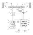
- FIG. 1 is a system diagram illustrating a vehicle steering system according to a first embodiment.
- 3 is a control block diagram of a turning control unit 19.
- FIG. 3 is a control block diagram of a steering reaction force control unit 20.
- FIG. 4 is a control block diagram of a disturbance suppression command turning angle calculation unit 32.
- FIG. 6 is a control block diagram of a repulsive force calculation unit 37 according to a yaw angle. It is a control block diagram of the repulsive force calculation unit 38 according to the lateral position. It is a figure which shows the control area
- FIG. 6 It is a time chart which shows a yaw angle change when the vehicle which is driving
- 6 is a time chart showing yaw angle change and lateral position change when lateral position F / B control is not performed when a vehicle traveling on a straight road on a highway receives continuous lateral wind.
- 6 is a time chart showing a yaw angle change and a lateral position change when lateral position F / B control is performed when a vehicle traveling on a straight road on a highway receives continuous lateral wind.
- 4 is a control block diagram of a lateral force offset unit 34.
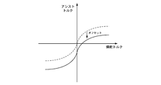
- FIG. 6 is a characteristic diagram showing a relationship between a steering angle of a steering wheel and a steering torque of a driver. By offsetting the steering reaction force characteristic representing the steering reaction torque according to the self-aligning torque in the same direction as the self-aligning torque, the characteristic indicating the relationship between the steering angle of the steering wheel and the steering torque of the driver has changed. It is a figure which shows a state.
- 4 is a control block diagram of a steering reaction force torque offset unit 36.
- FIG. FIG. 5 is a control block diagram of a reaction force calculation unit 39 corresponding to a departure allowance time.
- FIG. 6 is a characteristic diagram showing a relationship between a steering angle of a steering wheel and a steering torque of a driver. The relationship between the steering angle of the steering wheel and the steering torque of the driver is shown by offsetting the steering reaction force characteristic representing the steering reaction force torque according to the self-aligning torque in the direction in which the absolute value of the steering reaction force torque increases. It is a figure which shows the state from which the characteristic changed.
- FIG. 5 is a system diagram showing a vehicle steering system according to a second embodiment.
- 4 is a control block diagram of the assist torque control unit 28.
- FIG. 4 is a control block diagram of an assist torque offset unit 42.
- FIG. It is a figure which shows the state which the assist torque characteristic showing the assist torque according to a steering torque offset in the direction in which the absolute value of an assist torque becomes small.
- Steering part 2 Steering part 3 Backup clutch 4 SBW controller 5FL, 5FR Front left and right wheels 6 Steering wheel 7 Column shaft 8 Reaction force motor 9 Steering angle sensor 11 Pinion shaft 12 Steering gear 13 Steering motor 14 Steering angle sensor 15 Rack gear 16 racks 17 Camera 18 Vehicle speed sensor 19 Steering control unit 19a Adder 20 Steering reaction force controller 20a subtractor 20b adder 20c adder 21 Video processor 22 Current driver 23 Current driver 24 Navigation system 25 EPS controller 26 Torque sensor 27 Power steering motor 28 Assist torque control unit 28a subtractor 29 Current driver 31 Command turning angle calculator 32 Disturbance suppression command turning angle calculator 32a Yaw angle calculator 32b Curvature calculator 32c Horizontal position calculator 32d adder 32e Target yaw moment calculator 32f Target yaw acceleration calculator 32g target yaw rate calculator 32h Command turning angle calculator 32i limiter processor 33 Lateral force calculator 34 Lateral force offset 34a Curvature calculator 34b Upper / lower limiter 34c SAT gain calculator 34d multiplier
- FIG. 1 is a system diagram illustrating a vehicle steering system according to the first embodiment.
- the steering device according to the first embodiment mainly includes a steering unit 1, a steering unit 2, a backup clutch 3, and an SBW controller 4, a steering unit 1 that receives a steering input from a driver, and left and right front wheels (steered wheels) 5FL, 5FR.
- a steer-by-wire (SBW) system in which the steering unit 2 that steers the vehicle is mechanically separated is employed.
- the steering unit 1 includes a steering wheel 6, a column shaft 7, a reaction force motor 8, and a steering angle sensor 9.
- the column shaft 7 rotates integrally with the steering wheel 6.
- the reaction force motor 8 is, for example, a brushless motor, the output shaft of which is a coaxial motor coaxial with the column shaft 7, and outputs a steering reaction force torque to the column shaft 7 in response to a command from the SBW controller 4.
- the steering angle sensor 9 detects the absolute rotation angle of the column shaft 7, that is, the steering angle of the steering wheel 6.
- the steered portion 2 includes a pinion shaft 11, a steering gear 12, a steered motor 13, and a steered angle sensor 14.
- the steering gear 12 is a rack and pinion type steering gear, and steers the front wheels 5L and 5R according to the rotation of the pinion shaft 11.
- the steered motor 13 is, for example, a brushless motor, whose output shaft is connected to the rack gear 15 via a reduction gear (not shown), and steers the front wheels 5 to the rack 16 in response to a command from the SBW controller 4.
- the steering torque is output.
- the turning angle sensor 14 detects the absolute rotation angle of the turning motor 13.
- the steered angle of the front wheels 5 can be detected from the rotational angle of the steered motor 13.
- the backup clutch 3 is provided between the column shaft 7 of the steering unit 1 and the pinion shaft 11 of the steering unit 2, and mechanically separates the steering unit 1 and the steering unit 2 by release, and the steering unit 1 by fastening. And the steering unit 2 are mechanically connected.
- the SBW controller 4 is input with the image of the traveling road ahead of the vehicle photographed by the camera 17 and the vehicle speed (vehicle speed) detected by the vehicle speed sensor 18.
- the SBW controller 4 includes a steering control unit 19 that controls the steering angles of the front wheels 5FL and 5FR, a steering reaction force control unit 20 that controls a steering reaction force torque applied to the column shaft 7, and a video processing unit 21.
- the turning control unit 19 generates a command turning angle based on each input information, and outputs the generated command turning angle to the current driver 22.
- the current driver 22 controls the command current to the steered motor 13 by angle feedback that matches the actual steered angle detected by the steered angle sensor 14 with the commanded steered angle.
- the steering reaction force control unit 20 generates a command steering reaction force torque based on each input information, and outputs the generated command steering reaction force torque to the current driver 23.
- the current driver 23 controls the command current to the reaction force motor 8 by torque feedback that matches the actual steering reaction force torque estimated from the current value of the reaction force motor 8 with the command steering reaction force torque.
- the video processing unit 21 recognizes the white lines (traveling line dividing lines) on the left and right of the traveling lane by image processing such as edge extraction from the image of the traveling path ahead of the host vehicle taken by the camera 17.
- the SBW controller 4 engages the backup clutch 3 to mechanically connect the steering unit 1 and the steered unit 2 to move the rack 16 in the axial direction by steering the steering wheel 6. Make it possible.
- control equivalent to an electric power steering system that assists the steering force of the driver by the assist torque of the steering motor 13 may be performed.
- SBW system a redundant system including a plurality of sensors, controllers, and motors may be used. Further, the steering control unit 19 and the steering reaction force control unit 20 may be separated.
- Stability control performs two feedback (F / B) controls for the purpose of improving vehicle stability against disturbances (crosswind, road surface unevenness, dredging, road surface cant, etc.).
- F / B two feedback
- the steering angle is corrected according to the yaw angle, which is the angle between the white line and the direction of travel of the vehicle, and the yaw angle generated by the disturbance is reduced.
- Lateral position F / B control The steering angle is corrected according to the distance to the white line (lateral position), and the lateral position change, which is the integrated value of the yaw angle caused by the disturbance, is reduced.
- the corrected steering reduction control performs three reaction force offset controls for the purpose of improving the stability of the vehicle with respect to the driver's steering input.
- Reaction force offset control according to the lateral position The steering reaction force characteristic according to the self-aligning torque is offset according to the lateral position in the direction in which the absolute value of the steering reaction force increases, and the driver crosses the steering angle neutral position. It is possible to prevent the sign of the steering torque from being reversed when corrective steering is performed.
- Reaction force offset control according to the deviation margin time Offset the steering reaction force characteristic according to the self-aligning torque in the direction in which the absolute value of the steering reaction force increases according to the deviation margin time (time to reach the white line).
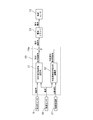
- FIG. 2 is a control block diagram of the steering control unit 19.
- the SBW command turning angle calculation unit 31 calculates the SBW command turning angle based on the steering angle and the vehicle speed.
- the disturbance suppression command turning angle calculation unit 32 calculates a disturbance suppression command turning angle for correcting the SBW command turning angle in the stability control based on the vehicle speed and the white line information. Details of the disturbance suppression command turning angle calculation unit 32 will be described later.
- the adder 19a outputs a value obtained by adding the SBW command turning angle and the disturbance suppression command turning angle to the current driver 22 as a final command turning angle.
- FIG. 3 is a control block diagram of the steering reaction force control unit 20.
- the lateral force calculation unit 33 refers to a steering angle-lateral force conversion map that represents the relationship between the steering angle for each vehicle speed and the tire lateral force in a conventional steering device that has been obtained in advance through experiments or the like based on the steering angle and the vehicle speed. To calculate the tire lateral force.
- the larger the steering angle the greater the tire lateral force, and when the steering angle is small, the amount of change in the tire lateral force relative to the amount of change in the steering angle is greater than when the steering angle is large.
- the tire has a characteristic that the tire lateral force decreases as the value increases.
- the lateral force offset unit 34 calculates a lateral force offset amount for offsetting the steering reaction force characteristic in the reaction force offset control according to the curvature based on the vehicle speed and the white line information. Details of the lateral force offset unit 34 will be described later.
- the subtractor 20a subtracts the lateral force offset amount from the tire lateral force.
- the SAT calculation unit 35 is a lateral force that represents the relationship between the tire lateral force and the steering reaction force torque in the conventional steering system, which is obtained in advance through experiments or the like based on the vehicle speed and the tire lateral force after offset based on the lateral force offset amount.
- the steering reaction force torque generated by the tire lateral force is calculated with reference to the steering reaction force torque conversion map.
- the tire lateral force-steering reaction torque conversion map shows that the larger the tire lateral force is, the larger the steering reaction torque becomes.
- the amount of change in the steering reaction torque with respect to the amount of change in the tire lateral force is larger than when the tire lateral force is large.
- the steering reaction torque decreases as the vehicle speed increases.
- This characteristic simulates the reaction force generated in the steering wheel by the self-aligning torque in which the wheel generated by the road surface reaction force returns to the straight traveling state in the conventional steering device.
- the adder 20b adds the steering reaction force torque and the steering reaction force torque component (spring term, viscosity term, inertia term) corresponding to the steering characteristics.
- the spring term is a component proportional to the steering angle, and is calculated by multiplying the steering angle by a predetermined gain.
- the viscosity term is a component proportional to the steering angular velocity, and is calculated by multiplying the steering angular velocity by a predetermined gain.
- the inertia term is a component proportional to the steering angular acceleration, and is calculated by multiplying the steering angular acceleration by a predetermined gain.
- the steering reaction force torque offset unit 36 is a steering reaction force torque for offsetting the steering reaction force characteristic in the reaction force offset control according to the lateral position or the deviation margin time based on the vehicle speed and the image of the traveling road ahead of the host vehicle. Calculate the offset amount. Details of the steering reaction torque offset unit 36 will be described later.
- the reaction force offset control suppressing unit 43 includes a counter 43a and a steering reaction force torque offset amount limiting unit 43b.
- the steering reaction force torque offset amount limiting unit 43b starts the reaction force offset control suppression process. In the reaction force offset control suppression process, the steering reaction force torque offset amount is limited.
- the adder 20c outputs a value obtained by adding the steering reaction force torque after adding the steering reaction force torque component corresponding to the steering characteristics and the steering torque offset amount to the current driver 23 as a final command steering reaction force torque. .
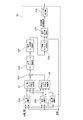
- FIG. 4 is a control block diagram of the disturbance suppression command turning angle calculation unit 32.
- the yaw angle calculator 32a calculates a yaw angle that is an angle formed by the white line at the forward gazing point and the traveling direction of the host vehicle.
- the yaw angle at the forward gazing point is an angle formed by the white line after a predetermined time (for example, 0.5 seconds) and the traveling direction of the vehicle.
- the curvature calculation unit 32b calculates the curvature of the white line at the forward gazing point.
- the lateral position calculation unit 32c calculates the distance to the white line at the front gazing point. Based on the yaw angle, the curvature, and the vehicle speed, the repulsive force calculation unit 37 corresponding to the yaw angle calculates the vehicle repulsive force for reducing the yaw angle generated by the disturbance in the yaw angle F / B control. Details of the repulsive force calculation unit 37 according to the yaw angle will be described later.
- the repulsive force calculation unit 38 according to the lateral position is used to reduce lateral position changes caused by disturbances in lateral position F / B control. Calculate the repulsive force of the vehicle. Details of the repulsive force calculation unit 38 according to the lateral position will be described later.
- the adder 32d adds the repulsive force according to the yaw angle and the repulsive force according to the lateral position, and calculates the lateral repulsive force.
- the target yaw moment calculator 32e calculates a target yaw moment based on the lateral repulsive force, the wheel base (distance between the axles), the rear wheel axle weight, and the front wheel axle weight. Specifically, a value obtained by multiplying the lateral repulsive force by the ratio of the rear wheel axle weight to the vehicle weight (front wheel axle weight + rear wheel axle weight) and the wheel base is set as the target yaw moment.
- the target yaw acceleration calculation unit 32f multiplies the target yaw moment by the yaw inertia moment coefficient to calculate the target yaw acceleration.
- the target yaw rate calculation unit 32g calculates the target yaw rate by multiplying the target yaw acceleration by the vehicle head time.
- the command turning angle calculation unit 32h calculates a disturbance suppression command turning angle ⁇ st * with reference to the following formula based on the target yaw rate ⁇ * , the wheel base WHEEL_BASE, the vehicle speed V, and the vehicle characteristic speed vCh.
- the vehicle characteristic speed V ch is a parameter in the known “Ackermann equation” and represents the self-steering characteristic of the vehicle.
- ⁇ st * ( ⁇ * ⁇ WHEEL_BASE ⁇ (1+ (V / vCh) 2 ) ⁇ 180) / (V ⁇ M_PI) M_PI is a predetermined coefficient.
- the limiter processing unit 32i limits the maximum value of the disturbance suppression command turning angle ⁇ st * and the upper limit of the change rate.
- the maximum value is in a play angle range (for example, 3 ° to the left and right) of the steering wheel 6 near the neutral position in a conventional steering device (the steering unit and the steering unit are mechanically connected).
- the turning angle range of the front wheels 5FL and 5FR corresponding to the range of play at that time (for example, right and left 0.2 °).
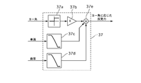
- FIG. 5 is a control block diagram of the repulsive force calculation unit 37 according to the yaw angle.
- the upper / lower limiter 37a performs upper / lower limiter processing on the yaw angle.
- the upper / lower limiter is greater than or equal to a predetermined value capable of suppressing disturbance, and A value that is less than a value that causes the vehicle to vibrate and a value that is generated by the steering of the driver (for example, 1 °), and 0 if the yaw angle is negative.
- the yaw angle F / B gain multiplication unit 37b multiplies the yaw angle after the limiter process by the yaw angle F / B gain.
- the yaw angle F / B gain is equal to or greater than a predetermined value that can ensure responsiveness while avoiding insufficient control amount, and less than the value at which the vehicle vibrates and the driver feels the neutral deviation between the steering angle and the turning angle.
- the vehicle speed correction gain multiplication unit 37c multiplies the vehicle speed by the vehicle speed correction gain.
- the vehicle speed correction gain has a maximum value in the range of 0 to 70 km / h, a gradual decrease in the range of 70 to 130 km / h, and a minimum value (0) in the range of 130 km / h or higher.
- the curvature correction gain multiplication unit 37d multiplies the curvature by the curvature correction gain.
- the curvature correction gain has a characteristic that decreases as the curvature increases, and an upper limit and a lower limit (0) are set.
- the multiplier 37e multiplies the outputs of the yaw angle F / B gain multiplication unit 37b, the vehicle speed correction gain multiplication unit 37c, and the curvature correction gain multiplication unit 37d to obtain a repulsive force according to the yaw angle.
- FIG. 6 is a control block diagram of the repulsive force calculation unit 38 according to the lateral position.
- the subtractor 38a obtains the lateral position deviation by subtracting the distance from the preset lateral position threshold (for example, 90 cm) to the white line at the front gazing point.
- the upper / lower limiter 38b performs upper / lower limiter processing on the lateral position deviation.
- the upper / lower limiter takes a predetermined positive value when the lateral position deviation is a positive value, and is 0 when the lateral position deviation is a negative value.
- the distance correction gain multiplication unit 38c multiplies the distance to the white line at the front gaze point by the distance correction gain.
- the distance correction gain takes a maximum value when the distance to the white line is equal to or smaller than a predetermined value, and when the distance exceeds the predetermined value, the distance correction gain has a characteristic that becomes smaller as the distance becomes longer, and a lower limit is set.
- the horizontal position F / B gain multiplication unit 38d multiplies the distance to the white line corrected by the distance correction gain multiplication unit 38c by the horizontal position F / B gain.
- the lateral position F / B gain is set to a value that is equal to or greater than a predetermined value that can ensure responsiveness while avoiding a shortage of control amount, and that is less than a value that makes the vehicle vibrate and a value that the driver feels neutral deviation.
- a value smaller than the yaw angle F / B gain of the B gain calculation unit 37b is set.
- the vehicle speed correction gain multiplication unit 38e multiplies the vehicle speed by the vehicle speed correction gain.
- the vehicle speed correction gain has a maximum value in the range of 0 to 70 km / h, a gradual decrease in the range of 70 to 130 km / h, and a minimum value (0) in the range of 130 km / h or higher.
- the curvature correction gain multiplication unit 38f multiplies the curvature by the curvature correction gain.
- the curvature correction gain has a characteristic that decreases as the curvature increases, and an upper limit and a lower limit (0) are set.
- the multiplier 38g multiplies each output of the lateral position F / B gain multiplication unit 38d, the vehicle speed correction gain multiplication unit 38e, and the curvature correction gain multiplication unit 38f to obtain a repulsive force according to the lateral position.
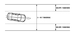
- the yaw angle F / B control for reducing the yaw angle caused by the disturbance and the lateral position F / B control for reducing the lateral position change that is an integral value of the yaw angle caused by the disturbance.
- the yaw angle F / B control is performed regardless of the lateral position when the yaw angle occurs.
- the lateral position F / B control is performed when the distance to the white line is equal to or less than the predetermined lateral position threshold (90 cm). carry out. That is, the vicinity of the center of the traveling lane is a dead zone for lateral position F / B control.
- the control area of both F / B controls is shown in FIG. ⁇ is the yaw angle.
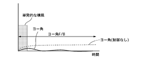
- FIG. 8 is a time chart showing a change in yaw angle when a vehicle traveling on a straight road on a highway receives a single crosswind, and it is assumed that the vehicle is traveling near the center of the traveling lane.
- the yaw angle F / B control calculates the repulsive force according to the yaw angle, finds the disturbance suppression command turning angle to obtain the repulsive force, The SBW command turning angle based on the steering angle and the vehicle speed is corrected.
- the yaw angle is zero because the direction of the white line and the traveling direction of the vehicle coincide with each other, particularly on a straight road.
- the generated yaw angle is considered to be due to disturbance, and by reducing the yaw angle, the stability of the vehicle against disturbance can be improved particularly during straight running.
- the driver's correction steering amount can be reduced.
- 5R can be controlled independently of each other, and the command turning angle is obtained by adding the SBW command turning angle according to the steering angle and the vehicle speed and the disturbance suppression command turning angle according to the yaw angle. Based on this, the steering angle of the front wheels 5L, 5R is controlled, while the tire lateral force is estimated based on the steering angle and the vehicle speed, and the steering reaction force is determined based on the commanded steering reaction force according to the estimated tire lateral force and the vehicle speed. Control power. That is, since the turning angle corresponding to the disturbance suppression is directly given to the front wheels 5L and 5R, it is not necessary to provide a steering reaction force component that prompts the steering for disturbance suppression.
- the fluctuation of the tire lateral force caused by the steering for suppressing the disturbance is not reflected in the steering reaction force, so the driver feels uncomfortable. Can be reduced.
- a tire lateral force is estimated from a rack axial force and a turning angle detected by a sensor, and a steering reaction force corresponding to the estimated tire lateral force is applied. For this reason, the fluctuation of the tire lateral force generated by the steering for suppressing the disturbance is always reflected in the steering reaction force, which makes the driver feel uncomfortable.
- the uncomfortable feeling given to the driver can be reduced.
- the disturbance suppression command turning angle is changed to conventional.
- the steering wheel 6 is in the play angle range near the steering angle neutral position (left and right 3 °)
- the generation of the yaw angle due to disturbance is more conspicuous when traveling straight than when turning, and the steering angle is located near the steering angle neutral position when traveling straight.
- the correction of the turning angle by the yaw angle F / B control is almost always performed near the steering angle neutral position, so the steering angle and the turning angle associated with the provision of the disturbance suppression command turning angle By suppressing the amount of neutral deviation within the range of steering play, it is possible to suppress a sense of incongruity associated with neutral deviation.
- the disturbance suppression command turning angle is limited to a range of 0.2 ° to the left and right, the driver can change the traveling direction of the vehicle to a desired direction by the steering input even during the stability control.
- the amount of correction of the turning angle based on the disturbance suppression command turning angle is very small with respect to the amount of change in the turning angle caused by the driver's steering input. Can be realized.
- lane departure prevention control that gives the vehicle a yaw moment that avoids departure when a vehicle traveling lane departure tendency is detected, or the vehicle travels near the center of the traveling lane.
- Lane keeping control for imparting a yaw moment to a vehicle is known.
- the lane departure prevention control is a control having a threshold for control intervention, and the control does not operate in the vicinity of the center of the traveling lane, so the stability of the vehicle against disturbance cannot be ensured. Further, even when the driver wants to bring the vehicle to the end of the traveling lane, control intervention is performed according to the threshold value, which causes trouble for the driver.
- the control has a target position (target line), and although the stability of the vehicle against disturbance can be ensured, a line deviating from the target line cannot be driven.
- the control is canceled by determining that the steering wheel is released, so the driver must always grip the steering wheel with a certain force or more, and the driver's steering load is reduced. large.
- the yaw angle F / B control of the first embodiment does not have a threshold value for control intervention, it is possible to always ensure stability against disturbance by seamless control.
- the driver since it does not have a target position, the driver can drive the vehicle along a favorite line. In addition, even when the steering wheel 6 is held lightly, the control is not released, and the steering load on the driver can be reduced.
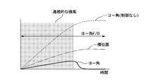
- FIG. 9 is a time chart showing the yaw angle change and the lateral position change when the lateral position F / B control is not performed when the vehicle traveling on the straight road of the expressway receives continuous lateral wind. Is driving near the center of the driving lane.
- the yaw angle F / B control reduces the yaw angle, and when the yaw angle is zero, the turning angle is not corrected, so the lateral position change, which is the integrated value of the yaw angle caused by the disturbance, is directly detected.
- the yaw angle multiplied by the yaw angle F / B gain is limited to the upper limit (1 °) or less by the upper / lower limiter 37a.
- the repulsive force according to the yaw angle is a repulsive force corresponding to a yaw angle smaller than the actual yaw angle. From this point, the lateral flow of the vehicle can be effectively suppressed only by the yaw angle F / B control. Proves difficult.
- FIG. 10 is a time chart showing changes in yaw angle and lateral position when lateral position F / B control is performed when a vehicle traveling on a straight road on a highway receives continuous lateral wind.
- position F / B control when the vehicle running near the center of the lane is subjected to continuous crosswinds and flows laterally, and the distance to the white line is less than the lateral position threshold, the lateral position changes ( ⁇ yaw angle integral value). The corresponding repulsive force is calculated.
- the disturbance suppression command turning angle calculation unit 32 calculates the disturbance suppression command turning angle based on the lateral repulsive force that is the sum of the repulsive force according to the lateral position and the repulsive force according to the yaw angle. Correct the corners. That is, in the lateral position F / B control, the SBW command turning angle is corrected by the disturbance suppression command turning angle according to the lateral position, so it is possible to directly reduce the lateral position change due to steady disturbance. Yes, the lateral flow of the vehicle can be suppressed. In other words, the travel position of the vehicle that performs the yaw angle F / B control can be returned to the vicinity of the center of the travel lane, which is the dead zone of the lateral position F / B control.
- the stability control of the first embodiment reduces the yaw angle change due to the transient disturbance by the yaw angle F / B control, and the yaw angle integral value (lateral position change) due to the steady disturbance is changed to the horizontal position.
- Reduction by F / B control can improve both vehicle stability against transient and steady disturbances.
- the stability control of the first embodiment is such that the driver is not aware of the vehicle behavior caused by the control (giving the disturbance suppression command turning angle) and does not disturb the vehicle behavior change caused by the driver's steering. This is possible without limiting the driver to be aware that the stability control is being performed because the change in the self-aligning torque caused by the control is not reflected in the steering reaction force.
- the lateral position F / B control the lateral position F / B gain for obtaining the repulsive force according to the lateral position is set to a value smaller than the yaw angle F / B gain.
- the yaw angle F / B control is required to converge the yaw angle before the driver feels a change in yaw angle due to a transient disturbance.
- B control is required to stop increasing the lateral position change, and it takes time for the lateral position to change due to the accumulation of the yaw angle integral value. Is not necessary.
- the control amount fluctuates greatly depending on the magnitude of the disturbance, giving the driver a sense of incongruity.
- FIG. 11 is a control block diagram of the lateral force offset unit 34.
- the curvature calculation unit 34a calculates the curvature of the white line at the forward gazing point. As the white line, either the left or right white line may be used.
- the upper / lower limiter 34b performs upper / lower limiter processing on the vehicle speed.
- the SAT gain calculation unit 34c calculates the SAT gain according to the vehicle speed based on the vehicle speed after the limiter process.
- the SAT gain has a characteristic that increases as the vehicle speed increases, and an upper limit is set.
- the multiplier 34d obtains the lateral force offset amount by multiplying the SAT gain by the curvature.
- the limiter processing unit 34e limits the maximum value of the lateral force offset amount and the upper limit of the change rate. For example, the maximum value is 1,000 N, and the upper limit of the change rate is 600 N / s.
- reaction force offset control according to curvature obtains a larger lateral force offset amount as the curvature of the white line is larger, and subtracts it from the tire lateral force.
- the steering reaction force torque corresponding to the tire lateral force calculated by the SAT calculation unit 35 that is, the steering reaction force characteristic indicating the steering reaction force torque corresponding to the self-aligning torque, is shown in FIG.
- the self-aligning torque is offset in the same sign direction. Note that FIG. 12 shows the case of the right curve, and the case of the left curve is offset in the opposite direction to FIG.
- a steering reaction force characteristic that simulates the steering reaction force according to the self-aligning torque in the conventional steering device is set, and the steering reaction force A steering reaction force is applied to the steering wheel based on the characteristics.
- the relationship between the steering angle of the steering wheel and the steering torque of the driver is a characteristic A as shown in FIG. That is, the larger the absolute value of the steering angle, the larger the absolute value of the steering torque.
- the absolute value of the steering angle is small, the amount of change of the steering torque with respect to the amount of change of the steering angle becomes larger than when the absolute value of the steering angle is large.
- the steering reaction force characteristic representing the steering reaction force torque corresponding to the self-aligning torque becomes the same sign direction as the self-aligning torque as the curvature of the white line is larger.
- the characteristic representing the relationship between the steering angle and the steering torque is offset in the same sign direction as the steering angle, and changes from characteristic A to characteristic B.
- the driver reduces the fixed steering torque to T 4, the reduction amount [Delta] T 3-4 of steering holding torque Figure
- the decrease amount ⁇ 1-4 of the steering angle is smaller than the decrease amount ⁇ 1-2 of the prior art.
- the greater the curvature of the curve the smaller the fluctuation of the steering angle with respect to the change in the steering torque and the lower the sensitivity of the vehicle to the steering torque, so that the behavior change of the vehicle becomes gradual and the course correction by the driver is facilitated. be able to.
- the steering torque T 3 ( ⁇ T 1 ) for maintaining the steering angle ⁇ 1 can be made smaller than that of the prior art, the driver's steering burden during turning can be reduced.
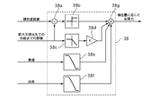
- FIG. 15 is a control block diagram of the steering reaction force torque offset unit 36.
- the yaw angle calculator 36a calculates the yaw angle at the forward gazing point. By calculating the yaw angle based on the image of the travel path taken by the camera 17, the yaw angle can be detected easily and with high accuracy.
- As the white line either the left or right white line may be used.
- the horizontal position calculation unit 36b calculates a horizontal position with respect to the left and right white lines at the forward gazing point and a horizontal position with respect to the left and right white lines at the current position.
- the horizontal position calculation unit 36b switches the horizontal position with respect to the left and right white lines at the current position. That is, the horizontal position with respect to the left white line before reaching the white line is set as the horizontal position with respect to the right white line after reaching the white line, and the horizontal position with respect to the right white line before reaching the white line is set as the horizontal position with respect to the left white line after reaching the white line.
- the value W 2 / W 1 obtained by dividing the lane width W 2 of the lane after the lane change by the lane width W 1 of the lane before the lane change is replaced.
- the horizontal position is corrected by multiplying the horizontal position.
- the lane width information of each traveling lane is acquired from the navigation system 24.
- the reaction force calculation unit 39 corresponding to the departure allowance time calculates the reaction force corresponding to the departure allowance time based on the vehicle speed, the yaw angle, and the lateral position with respect to the left and right white lines at the front gazing point. Details of the reaction force calculation unit 39 according to the departure allowance time will be described later.
- the reaction force calculation unit 40 according to the lateral position calculates a reaction force according to the lateral position based on the lateral position with respect to the left and right white lines at the current position. Details of the reaction force calculation unit 40 according to the lateral position will be described later.
- the reaction force selection unit 36c selects, as the steering reaction force torque offset amount, the larger absolute value among the reaction force according to the departure allowance time and the reaction force according to the lateral position.
- the limiter processing unit 36d limits the maximum value of the steering reaction force torque offset amount and the upper limit of the change rate. For example, the maximum value is 2 Nm, and the upper limit of the change rate is 10 Nm / s.
- FIG. 16 is a control block diagram of the reaction force calculation unit 39 according to the departure allowance time.
- the multiplier 39a obtains the lateral speed of the vehicle by multiplying the yaw angle by the vehicle speed.
- the divider 39b divides the lateral position with respect to the left white line at the forward gazing point by the lateral speed to obtain a deviation margin time with respect to the left white line.
- the divider 39c divides the lateral position with respect to the right white line at the forward gazing point by the lateral speed to obtain a deviation margin time with respect to the right white line.
- the deviation margin time selection unit 39d selects the shorter of the deviation margin times for the left and right white lines as the deviation margin time.
- the reaction force calculator 39e according to the departure allowance time calculates a reaction force according to the departure allowance time based on the departure allowance time.
- the reaction force according to the deviation margin time is inversely proportional to the deviation margin time (proportional to the reciprocal of the deviation margin time), and has a characteristic of almost zero after 3 seconds.
- FIG. 17 is a control block diagram of the reaction force calculation unit 40 according to the lateral position.
- the subtractor 40a obtains a lateral position deviation with respect to the left lane by subtracting the lateral position with respect to the left lane from a preset target left lateral position (for example, 90 cm).
- the subtractor 40b subtracts the lateral position with respect to the right lane from a preset target right lateral position (for example, 90 cm) to obtain a lateral position deviation with respect to the right lane.
- the lateral position deviation selection unit 40c selects the larger one of the lateral position deviations with respect to the left and right lanes as the lateral position deviation.
- the reaction force calculation unit 40d according to the lateral position deviation calculates a reaction force according to the lateral position based on the lateral position deviation.
- the reaction force according to the lateral position has a characteristic that increases as the lateral position deviation increases, and an upper limit is set.
- reaction force offset control action according to lateral position In the reaction force offset control according to the lateral position, the reaction force according to the lateral position is added to the steering reaction force torque as a steering reaction force torque offset amount.
- the steering reaction force characteristic representing the steering reaction force torque corresponding to the self-aligning torque is offset in a direction in which the absolute value of the steering reaction force torque increases as the distance to the white line decreases, as shown in FIG.
- the FIG. 18 shows a case where the vehicle is close to the right lane. When the vehicle is close to the left lane, the vehicle is offset in the opposite direction to FIG.
- the driving position of the vehicle is shifted to the right side due to the driver's unexpected increase in the right direction, and then the driver returns the driving position to the vicinity of the center of the driving lane by correction steering.
- the steering angle and steering torque when the driver performs an unexpected operation are set as the position of point P 1 on the characteristic A in FIG.
- the characteristic A is a characteristic representing the relationship between the steering angle and the steering torque when the steering reaction force characteristic simulating a conventional steering device is set, as in FIG.
- the steering reaction force torque according to the self-aligning torque is increased in the direction in which the absolute value of the steering reaction force torque increases as the distance to the white line is shorter.
- the characteristic representing the relationship between the steering angle and the steering torque by the offset is offset from the characteristic A as the distance to the white line becomes shorter as the absolute value of the steering torque is increased as shown in FIG. Changes continuously to C.
- the steering wheel 6 is gradually returned to the steering angle neutral position (point P 1 ⁇ point P 2 ), It is possible to prevent the vehicle travel position from shifting to the right side due to the driver's unexpected increase operation.
- the steering angle and the steering torque move from the point P 1 to the point P 3 .
- the steering torque neutral position is offset from the steering angle neutral position to the additional side, so the steering torque neutral position is increased when the steering angle is increased from the steering angle neutral position.
- the sign of the steering torque is not reversed until the position is reached. Therefore, the driver can control the turning angle of the front wheels 5L and 5R only by reducing the steering torque and stopping the rotation of the steering wheel 6 when the steering wheel 6 reaches the target angle.
- the reaction force offset control according to the lateral position of the first embodiment can facilitate the driver's correction steering because the direction in which the driver controls the force is difficult to switch. As a result, the travel position of the vehicle is less likely to overshoot, and the correction steering amount can be reduced.
- the offset amount is increased as the distance to the white line is shorter. Therefore, the steering torque neutral position is the steering angle neutral position as the distance to the white line is shorter. Is offset further away from When the driver performs corrective steering to return the vehicle travel position to the vicinity of the center of the travel lane, the closer the white line is, the greater the amount of additional operation from the steering angle neutral position is required. At this time, if the offset amount of the steering torque neutral position with respect to the steering angle neutral position is small, the steering torque may exceed the neutral position and the sign of the steering torque may be reversed before the steering wheel reaches the target angle. Therefore, it is possible to suppress the steering torque from exceeding the neutral position by increasing the offset amount as the distance to the white line is shorter.
- the lateral position calculation unit 36b switches the lateral position with respect to the left and right white lines at the current position when the host vehicle reaches the white line.
- the host vehicle is more likely to return to the vicinity of the center of the travel lane by increasing the steering reaction force as the host vehicle is further away from the vicinity of the center of the travel lane.
- the yaw angle integral value (lateral position change) is regarded as a disturbance, and the steering reaction force is controlled so as to guide the vehicle in a direction in which the yaw angle integral value disappears. For this reason, when a lane change is performed, it is necessary to reset the yaw angle integral value.
- the steering reaction force for returning the vehicle to the vicinity of the center of the traveling lane before the lane change continues to act even after the lane change, and the driver's operation is hindered. Note that the vehicle cannot be guided near the center of the travel lane after the lane change by simply setting the integral value to zero.
- the vehicle when the vehicle reaches the white line, it can be regarded as a driver's intentional operation. In this case, the lateral position with respect to the left and right white lines at the current position is switched. In order to guide the vehicle to the center of the lane after the lane change by switching the position where the vehicle is guided from the center of the lane before the lane change to the center of the lane after the lane change.
- the steering reaction force can be generated.
- reaction force offset control action according to deviation margin time In the reaction force offset control according to the departure allowance time, the reaction force according to the departure allowance time is added to the steering reaction force torque as the steering reaction force torque offset amount.
- the steering reaction force characteristic representing the steering reaction force torque corresponding to the self-aligning torque is offset in a direction in which the absolute value of the steering reaction force torque increases as the deviation margin time decreases, as shown in FIG.
- the FIG. 18 shows a case where the vehicle is close to the right lane. When the vehicle is close to the left lane, the vehicle is offset in the opposite direction to FIG.
- the characteristic representing the relationship between the steering angle and the steering torque is offset in the direction in which the absolute value of the steering torque increases as shown in FIG. 20, and from characteristic A to characteristic C as the deviation margin time becomes shorter. And change continuously.
- the steering angle neutral position point P 1 ⁇ point P 2
- the steering angle and the steering torque move from the point P 1 to the point P 3 .
- the steering torque neutral position is offset from the steering angle neutral position to the additional side, so the steering torque neutral position is increased when the steering angle is increased from the steering angle neutral position.
- the sign of the steering torque is not reversed until the position is reached. Therefore, the driver can control the turning angle of the front wheels 5L and 5R only by reducing the steering torque and stopping the rotation of the steering wheel 6 when the steering wheel 6 reaches the target angle. That is, the reaction force offset control according to the departure allowance time according to the first embodiment can facilitate the driver's correction steering because the direction in which the driver controls the force is difficult to switch. As a result, the travel position of the vehicle is less likely to overshoot, and the correction steering amount can be reduced.
- the offset amount is increased as the departure allowance time is shorter. Therefore, the steering torque neutral position is changed from the steering angle neutral position as the departure allowance time is shorter. Offset to a more distant position.
- the driver performs corrective steering to return the vehicle travel position to near the center of the travel lane, the shorter the deviation margin time, the closer to the white line, and the closer to the white line, the greater the amount of operation to increase from the steering angle neutral position.
- the offset amount of the steering torque neutral position with respect to the steering angle neutral position is small, the steering torque may exceed the neutral position and the sign of the steering torque may be reversed before the steering wheel reaches the target angle. Therefore, it is possible to suppress the steering torque from exceeding the neutral position by increasing the offset amount as the distance to the white line is shorter.
- the steering reaction force torque offset unit 36 selects the reaction force corresponding to the deviation margin time and the reaction force corresponding to the lateral position having the larger absolute value as the steering reaction force torque offset amount.
- the adder 20c adds the steering reaction torque offset amount to the steering reaction torque.
- the steering reaction force characteristic is offset in the direction in which the absolute value of the steering reaction force torque is increased in accordance with the departure allowance time or the lateral position.
- the reaction force offset control according to the departure allowance time when the vehicle and the white line are parallel, that is, when the yaw angle is zero, the reaction force according to the departure allowance time is zero.
- reaction force offset control according to the horizontal position
- a reaction force is generated in proportion to the distance to the white line, so a larger reaction force as the distance to the white line becomes shorter. And the vehicle can be easily returned to the vicinity of the center of the traveling lane.
- reaction force offset control according to the lateral position when the vehicle is near the center of the traveling lane, the reaction force according to the lateral position is zero. For this reason, even in the vicinity of the center of the traveling lane, when the yaw angle is large and the vehicle speed is high, it is difficult to increase the steering reaction force with good response while reaching the white line in a short time.
- reaction force offset control according to the departure allowance time a reaction force (reaction force according to the departure allowance time) is generated according to the departure allowance time, and the reaction force has a departure allowance time of 3 seconds.
- the steering reaction force can be increased with good response to suppress lane departure. Therefore, by using the reaction force offset control according to the departure allowance time and the reaction force offset control according to the lateral position, it is possible to effectively deviate from the lane while giving a stable reaction force according to the distance to the white line. Can be suppressed. At this time, the optimum steering reaction force that is always required can be applied by using the reaction force corresponding to the departure allowance time and the reaction force corresponding to the lateral position having the larger absolute value.
- reaction offset control suppression when one side white line is lost In the system that assists the steering continuously during traveling using the left and right white line information of the traveling lane, such as the reaction force offset control according to the lateral position and the departure allowance time in the first embodiment, the left and right white lines are far from the own vehicle. When the white line is lost and information on the other white line cannot be obtained, the control needs to be interrupted. As another method, the method of estimating the position of the white line from the past lane width and continuing the control can be considered, but on the road surface represented by the merging and merging, there is a difference between the actual lane width and the lane width used for estimation. Therefore, it is difficult to accurately estimate the position of the lost white line, which is not a preferable method.
- Example 1 has the following effects.
- Video processor 21 (white line detection means) that detects the left and right white lines of the driving lane and steering in the direction in which the vehicle approaches the white line when the vehicle approaches one of the detected white lines
- Steering reaction force torque offset portion 36 (white line approaching) that calculates a steering reaction force torque offset amount (white line approaching suppression steering reaction force) to be suppressed and increases the steering reaction force torque offset amount as the distance between the vehicle and the white line is closer.
- a suppression steering reaction force calculating means a steering reaction force control section 20 (steering reaction force control means) for controlling a steering reaction force applied to the steering section 1 that receives the steering input of the driver based on the steering reaction force torque offset amount;
- the reaction force offset control suppressing unit 43 that limits the steering reaction force torque offset amount when the increase gradient of the steering reaction force torque offset amount is equal to or less than a predetermined increase gradient. (Restricted hand Stage).
- the reaction force offset control suppression unit 43 limits the steering reaction force torque offset amount when the steering reaction force torque offset amount falls below the previous value. By starting limiting the steering reaction force torque offset amount when the steering reaction force torque offset amount shows a decreasing trend, the vehicle behavior approaches the vehicle behavior expected by the driver, so that the driver can feel less uncomfortable.
- the reaction force offset control suppressing unit 43 prohibits an increase in the steering reaction force torque offset amount and allows a decrease. Thereby, compared with the case where the steering reaction force torque offset amount is maintained, the vehicle behavior approaches the vehicle behavior expected by the driver, so that the uncomfortable feeling given to the driver can be further reduced.
- the reaction force offset control suppressing unit 43 determines that the other of the left and right white lines cannot be detected when the state in which the other of the left and right white lines cannot be detected continues for a predetermined time. As a result, when the loss of the white line is relatively short, such as when the white line can be detected immediately after it becomes undetectable, the reaction force offset control according to the lateral position and the deviation margin time can be continued. Lane departure can be suppressed.
- the steering reaction force control unit 20 adds the steering reaction force torque offset amount to the steering reaction force torque obtained from the predetermined steering reaction force characteristic according to the self-aligning torque acting on the left and right front wheels 5FL, 5FR.
- a steering reaction force is applied to the steering unit 1 based on the command steering reaction force.
- the steering unit 1 is mechanically separated from the steering unit 2 that steers the left and right front wheels 5FL, 5FR, and a curvature calculation unit 34a (curvature detection means) that detects the curvature of the white line, and the detected curvature is And a lateral force offset section 34 (offset amount calculating means) that calculates a larger lateral force offset amount as the larger the steering force, the steering reaction force control section 20 is offset from the self-aligning torque acting on the left and right front wheels 5FL, 5FR.
- the steering reaction force torque is applied to the steering unit 1 based on the commanded steering reaction force obtained from the offset self-aligning torque obtained by subtracting the amount and a predetermined steering reaction force characteristic corresponding to the self-aligning ork.
- the offset unit 36 does not limit the lateral force offset amount even when it is determined that the other of the left and right white lines cannot be detected. Since the curvature can be detected based on either the left or right white line, even if the other of the left and right white lines becomes undetectable, the reaction force offset control according to the curvature is not affected at all. Therefore, by continuing the reaction force offset control according to the curvature, it is possible to realize both the reduction of the driver's steering burden and the ease of course correction during turning.
- FIG. 21 is a system diagram illustrating a vehicle steering system according to the second embodiment.
- the steering device according to the second embodiment includes a steering unit 1, a steering unit 2, and an EPS controller 25 as main components.
- the steering unit 1 that receives a driver's steering input and the left and right front wheels (steered wheels) 5FL and 5FR are steered.
- the rudder part 2 is mechanically connected.
- the steering unit 1 includes a steering wheel 6, a column shaft 7, and a torque sensor 26.
- the torque sensor 26 detects the steering torque of the driver input from the steering wheel 6 to the column shaft 7.
- the steered portion 2 includes a pinion shaft 11, a steering gear 12, and a power steering motor 27.
- the pinion shaft 11 is connected to the column shaft 7 via a torsion bar of the torque sensor 26.
- the power steering motor 27 is, for example, a brushless motor, and an output shaft is connected to the rack gear 15 via a reduction gear (not shown), and assists the steering force of the driver to the rack 16 according to a command from the EPS controller 25. Outputs assist torque.
- the EPS controller 25 receives an image of the traveling road in front of the vehicle and the vehicle speed (body speed) detected by the vehicle speed sensor 18 taken by the camera 17.
- the EPS controller 25 includes an assist torque control unit (assist torque control means, controller) 28 and a video processing unit 21.
- the assist torque control unit 28 generates a command assist torque based on each input information, and outputs the generated command assist torque to the current driver 29.
- the current driver 29 controls the command current to the power steering motor 27 by torque feedback that matches the actual assist torque estimated from the current value of the power steering motor 27 with the command assist torque.
- the video processing unit 21 recognizes the white lines (traveling line dividing lines) on the left and right of the traveling lane by image processing such as edge extraction from the image of the traveling path ahead of the host vehicle taken by the camera 17.
- FIG. 22 is a control block diagram of the assist torque control unit 28.
- the assist torque calculator 41 calculates an assist torque based on the steering torque and the vehicle speed with reference to a preset assist torque map.
- the assist torque characteristic in the assist torque map has such a characteristic that it increases as the absolute value of the steering torque increases or the vehicle speed decreases.
- the assist torque offset unit 42 calculates an assist torque offset amount for offsetting the assist torque characteristic in the assist torque offset control according to the lateral position or the deviation margin time based on the vehicle speed and the image of the traveling road ahead of the host vehicle. . Details of the assist torque offset unit 42 will be described later.
- the subtractor 28a outputs a value obtained by subtracting the assist torque offset amount from the assist torque to the current driver 29 as a final command assist torque. [Assist torque offset section]
- FIG. 23 is a control block diagram of the assist torque offset unit 42.
- the reaction force selection unit 42c selects, as the assist torque offset amount, the larger absolute value of the reaction force according to the deviation allowance time and the reaction force according to the lateral position.
- the assist torque offset control suppressing unit 44 includes a counter 44a and an assist torque offset amount limiting unit 44b.
- the assist torque offset amount limiting unit 44b starts the assist torque offset control suppression process.
- the assist torque offset amount is limited. Specifically, when the assist torque offset amount exceeds the previous value, the previous value is output as the assist torque offset amount, and when the assist torque offset amount is less than the previous value, the current value is output.
Abstract
Description
ここで、単に制御を中断すると、ドライバは制御により生じる操舵反力の変化を想定した上で操舵を行っているため、ドライバの予期に反する操舵反力となり、ドライバに違和感を与えてしまう。
本発明の目的は、ドライバに与える違和感を軽減できる操舵制御装置を提供することにある。 In the above prior art, when the other of the left and right white lines (the one far from the vehicle) becomes undetectable during the control for assisting the driver's steering, the control amount of the control for assisting the driver's steering is one of the left and right white lines. Because it is based on the relationship with the Even in this case, it is necessary to interrupt the control for assisting the driver's steering.
Here, if the control is simply interrupted, the driver is steering on the assumption of a change in the steering reaction force caused by the control, so that the steering reaction force is against the driver's expectation, and the driver feels uncomfortable.
The objective of this invention is providing the steering control apparatus which can reduce the discomfort given to a driver.
2 転舵部
3 バックアップクラッチ
4 SBWコントローラ
5FL,5FR 左右前輪
6 ステアリングホイール
7 コラムシャフト
8 反力モータ
9 操舵角センサ
11 ピニオンシャフト
12 ステアリングギア
13 転舵モータ
14 転舵角センサ
15 ラックギア
16 ラック
17 カメラ
18 車速センサ
19 転舵制御部
19a 加算器
20 操舵反力制御部
20a 減算器
20b 加算器
20c 加算器
21 映像処理部
22 電流ドライバ
23 電流ドライバ
24 ナビゲーションシステム
25 EPSコントローラ
26 トルクセンサ
27 パワーステアリングモータ
28 アシストトルク制御部
28a 減算器
29 電流ドライバ
31 指令転舵角演算部
32 外乱抑制指令転舵角演算部
32a ヨー角演算部
32b 曲率演算部
32c 横位置演算部
32d 加算器
32e 目標ヨーモーメント演算部
32f 目標ヨー加速度演算部
32g 目標ヨーレイト演算部
32h 指令転舵角演算部
32i リミッタ処理部
33 横力演算部
34 横力オフセット部
34a 曲率演算部
34b 上下限リミッタ
34c SATゲイン演算部
34d 乗算器
34e リミッタ処理部
35 SAT演算部
36 操舵反力トルクオフセット部
36a ヨー角演算部
36b 横位置演算部
36c 反力選択部
36d リミッタ処理部
37 ヨー角に応じた反発力演算部
37a 上下限リミッタ
37b ヨー角F/Bゲイン乗算部
37c 車速補正ゲイン乗算部
37d 曲率補正ゲイン乗算部
37e 乗算器
38 横位置に応じた反発力演算部
38a 減算器
38b 上下限リミッタ
38c 距離補正ゲイン乗算部
38d 横位置F/Bゲイン乗算部
38e 車速補正ゲイン乗算部
38f 曲率補正ゲイン乗算部
38g 乗算器
39 逸脱余裕時間に応じ反力演算部
39a 乗算器
39b 除算器
39c 除算器
39d 逸脱余裕時間選択部
39e 逸脱余裕時間に応じた反力演算部
40 横位置に応じた反力演算部
40a 減算器
40b 減算器
40c 横位置偏差選択部
40d 横位置偏差に応じた反力演算部
41 アシストトルク演算部
42 アシストトルクオフセット部
42c 反力選択部
43 反力オフセット制御抑制部
43a カウンタ
43b 操舵反力トルクオフセット量制限部
44 アシストトルクオフセット制御抑制部
44a カウンタ
44b アシストトルクオフセット量制限部 1 Steering part
2 Steering part
3 Backup clutch
4 SBW controller
5FL, 5FR Front left and right wheels
6 Steering wheel
7 Column shaft
8 Reaction force motor
9 Steering angle sensor
11 Pinion shaft
12 Steering gear
13 Steering motor
14 Steering angle sensor
15 Rack gear
16 racks
17 Camera
18 Vehicle speed sensor
19 Steering control unit
19a Adder
20 Steering reaction force controller
20a subtractor
20b adder
20c adder
21 Video processor
22 Current driver
23 Current driver
24 Navigation system
25 EPS controller
26 Torque sensor
27 Power steering motor
28 Assist torque control unit
28a subtractor
29 Current driver
31 Command turning angle calculator
32 Disturbance suppression command turning angle calculator
32a Yaw angle calculator
32b Curvature calculator
32c Horizontal position calculator
32d adder
32e Target yaw moment calculator
32f Target yaw acceleration calculator
32g target yaw rate calculator
32h Command turning angle calculator
32i limiter processor
33 Lateral force calculator
34 Lateral force offset
34a Curvature calculator
34b Upper / lower limiter
34c SAT gain calculator
34d multiplier
34e Limiter processing section
35 SAT calculator
36 Steering reaction torque offset part
36a Yaw angle calculator
36b Horizontal position calculator
36c Reaction force selector
36d limiter processing section
37 Repulsive force calculation unit according to yaw angle
37a Upper / Lower Limiter
37b Yaw angle F / B gain multiplier
37c Vehicle speed correction gain multiplier
37d Curvature correction gain multiplier
37e multiplier
38 Repulsive force calculation unit according to lateral position
38a subtractor
38b Upper / Lower Limiter
38c Distance correction gain multiplier
38d Horizontal position F / B gain multiplier
38e Vehicle speed correction gain multiplier
38f Curvature correction gain multiplier
38g multiplier
39 Reaction force calculation section according to deviation margin time
39a multiplier
39b Divider
39c divider
39d Deviation margin time selector
39e Reaction force calculation unit according to deviation margin time
40 Reaction force calculation unit according to lateral position
40a subtractor
40b subtractor
40c Horizontal position deviation selector
40d Reaction force calculation unit according to lateral position deviation
41 Assist torque calculator
42 Assist torque offset
42c Reaction force selector
43 Reaction force offset control suppressor
43a counter
43b Steering reaction force torque offset amount limiter
44 Assist torque offset control suppressor
44a counter
44b Assist torque offset limiter
[システム構成]
図1は、実施例1の車両の操舵系を示すシステム図である。
実施例1の操舵装置は、操舵部1、転舵部2、バックアップクラッチ3、SBWコントローラ4を主要な構成とし、ドライバの操舵入力を受ける操舵部1と、左右前輪(転舵輪)5FL,5FRを転舵する転舵部2とが機械的に切り離されたステアバイワイヤ(SBW)システムを採用している。 [Example 1]
[System configuration]
FIG. 1 is a system diagram illustrating a vehicle steering system according to the first embodiment.
The steering device according to the first embodiment mainly includes a
コラムシャフト7は、ステアリングホイール6と一体に回転する。
反力モータ8は、例えば、ブラシレスモータであり、出力軸がコラムシャフト7と同軸の同軸モータであり、SBWコントローラ4からの指令に応じて、コラムシャフト7に操舵反力トルクを出力する。
操舵角センサ9は、コラムシャフト7の絶対回転角、すなわち、ステアリングホイール6の操舵角を検出する。 The
The
The
The
ステアリングギア12は、ラック&ピニオン式のステアリングギアであり、ピニオンシャフト11の回転に応じて前輪5L,5Rを転舵する。
転舵モータ13は、例えば、ブラシレスモータであり、出力軸が図外の減速機を介してラックギア15と接続され、SBWコントローラ4からの指令に応じて、ラック16に前輪5を転舵するための転舵トルクを出力する。
転舵角センサ14は、転舵モータ13の絶対回転角を検出する。ここで、転舵モータ13の回転角と前輪5の転舵角とは常に一意に定まる相関関係があるため、転舵モータ13の回転角から前輪5の転舵角を検出できる。以下では特に記載しない限り、前輪5の転舵角は転舵モータ13の回転角から算出されたものとする。
バックアップクラッチ3は、操舵部1のコラムシャフト7と転舵部2のピニオンシャフト11との間に設けられ、解放により操舵部1と転舵部2とを機械的に切り離し、締結により操舵部1と転舵部2とを機械的に接続する。 The steered
The
The steered
The turning
The
SBWコントローラ4は、前輪5FL,5FRの転舵角を制御する転舵制御部19と、コラムシャフト7に付与する操舵反力トルクを制御する操舵反力制御部20と、映像処理部21とを有する。
転舵制御部19は、各入力情報に基づいて指令転舵角を生成し、生成した指令転舵角を電流ドライバ22へ出力する。
電流ドライバ22は、転舵角センサ14により検出される実転舵角を指令転舵角と一致させる角度フィードバックにより転舵モータ13への指令電流を制御する。
操舵反力制御部20は、各入力情報に基づいて指令操舵反力トルクを生成し、生成した指令操舵反力トルクを電流ドライバ23へ出力する。
電流ドライバ23は、反力モータ8の電流値から推定される実操舵反力トルクを指令操舵反力トルクと一致させるトルクフィードバックにより反力モータ8への指令電流を制御する。
映像処理部21は、カメラ17により撮影された自車前方の走行路の映像からエッジ抽出等の画像処理によって走行車線左右の白線(走行路区分線)を認識する。
加えて、SBWコントローラ4は、SBWシステムのフェール時、バックアップクラッチ3を締結して操舵部1と転舵部2とを機械的に連結し、ステアリングホイール6の操舵によるラック16の軸方向移動を可能とする。このとき、転舵モータ13のアシストトルクによりドライバの操舵力を補助する電動パワーステアリングシステム相当の制御を行ってもよい。
上記SBWシステムにおいて、各センサ、各コントローラ、各モータを複数設けた冗長系としてもよい。また、転舵制御部19と操舵反力制御部20を別体としてもよい。 In addition to the
The
The turning
The
The steering reaction
The
The
In addition, when the SBW system fails, the
In the SBW system, a redundant system including a plurality of sensors, controllers, and motors may be used. Further, the
スタビリティ制御は、外乱(横風、路面凹凸、轍、路面カント等)に対する車両の安定性向上を目的とし、2つのフィードバック(F/B)制御を行う。
1.ヨー角F/B制御
白線と自車進行方向とのなす角度であるヨー角に応じて転舵角を補正し、外乱により発生したヨー角を減少させる。
2.横位置F/B制御
白線までの距離(横位置)に応じて転舵角を補正し、外乱により発生したヨー角の積分値である横位置変化を減少させる。 In the first embodiment, stability control and corrected steering reduction control are performed with the aim of reducing the driver's corrected steering amount and reducing the steering burden.
Stability control performs two feedback (F / B) controls for the purpose of improving vehicle stability against disturbances (crosswind, road surface unevenness, dredging, road surface cant, etc.).
1. Yaw angle F / B control The steering angle is corrected according to the yaw angle, which is the angle between the white line and the direction of travel of the vehicle, and the yaw angle generated by the disturbance is reduced.
2. Lateral position F / B control The steering angle is corrected according to the distance to the white line (lateral position), and the lateral position change, which is the integrated value of the yaw angle caused by the disturbance, is reduced.
1.横位置に応じた反力オフセット制御
横位置に応じてセルフアライニングトルクに応じた操舵反力特性を操舵反力の絶対値が大きくなる方向へオフセットし、ドライバが操舵角中立位置をまたぐ修正操舵を行ったときに操舵トルクの符号が反転するのを抑制する。
2.逸脱余裕時間に応じた反力オフセット制御
逸脱余裕時間(白線への到達時間)に応じてセルフアライニングトルクに応じた操舵反力特性を操舵反力の絶対値が大きくなる方向へオフセットし、ドライバが操舵角中立位置をまたぐ修正操舵を行ったときに操舵トルクの符号が反転するのを抑制する。
3.曲率に応じた反力オフセット制御
白線の曲率に応じてセルフアライニングトルクに応じた操舵反力特性をセルフアライニングトルクと同一符号方向へオフセットし、旋回時におけるドライバの保舵力を低減すると共に保舵力変化に対する保舵角変化を抑制する。 The corrected steering reduction control performs three reaction force offset controls for the purpose of improving the stability of the vehicle with respect to the driver's steering input.
1. Reaction force offset control according to the lateral position The steering reaction force characteristic according to the self-aligning torque is offset according to the lateral position in the direction in which the absolute value of the steering reaction force increases, and the driver crosses the steering angle neutral position. It is possible to prevent the sign of the steering torque from being reversed when corrective steering is performed.
2. Reaction force offset control according to the deviation margin time Offset the steering reaction force characteristic according to the self-aligning torque in the direction in which the absolute value of the steering reaction force increases according to the deviation margin time (time to reach the white line). When the driver performs corrective steering across the steering angle neutral position, the sign of the steering torque is prevented from being reversed.
3. Reaction force offset control according to the curvature The steering reaction force characteristic according to the self-aligning torque is offset in the same sign direction as the self-aligning torque according to the curvature of the white line to reduce the driver's steering force during turning. In addition, the steering angle change with respect to the steering force change is suppressed.
図2は、転舵制御部19の制御ブロック図である。
SBW指令転舵角演算部31は、操舵角と車速とに基づいてSBW指令転舵角を演算する。
外乱抑制指令転舵角演算部32は、車速と白線情報とに基づき、スタビリティ制御においてSBW指令転舵角を補正するための外乱抑制指令転舵角を演算する。外乱抑制指令転舵角演算部32の詳細については後述する。
加算器19aは、SBW指令転舵角と外乱抑制指令転舵角とを加算した値を最終的な指令転舵角として電流ドライバ22へ出力する。 [Steering control unit]
FIG. 2 is a control block diagram of the
The SBW command turning
The disturbance suppression command turning
The
図3は、操舵反力制御部20の制御ブロック図である。
横力演算部33は、操舵角と車速とに基づき、あらかじめ実験等により求めたコンベンショナルな操舵装置における車速毎の操舵角とタイヤ横力との関係を表す操舵角-横力変換マップを参照してタイヤ横力を演算する。操舵角-横力変換マップは、操舵角が大きいほどタイヤ横力が大きく、かつ、操舵角が小さいときは大きいときよりも操舵角の変化量に対するタイヤ横力の変化量が大きく、かつ、車速が高いほどタイヤ横力が小さくなる特性を有する。
横力オフセット部34は、車速と白線情報とに基づき、曲率に応じた反力オフセット制御において操舵反力特性をオフセットするための横力オフセット量を演算する。横力オフセット部34の詳細については後述する。
減算器20aは、タイヤ横力から横力オフセット量を減算する。
SAT演算部35は、車速と横力オフセット量によるオフセット後のタイヤ横力とに基づき、あらかじめ実験等により求めたコンベンショナルな操舵装置におけるタイヤ横力と操舵反力トルクとの関係を表す横力-操舵反力トルク変換マップを参照してタイヤ横力によって発生する操舵反力トルクを演算する。タイヤ横力-操舵反力トルク変換マップは、タイヤ横力が大きいほど操舵反力トルクが大きく、タイヤ横力が小さいときは大きいときよりもタイヤ横力の変化量に対する操舵反力トルクの変化量が大きく、かつ、車速が高いほど操舵反力トルクが小さくなる特性を有する。この特性は、コンベンショナルな操舵装置において、路面反力によって発生する車輪が直進状態に戻ろうとするセルフアライニングトルクによってステアリングホイールに発生する反力を模擬したものである。
加算器20bは、操舵反力トルクとステアリング特性に応じた操舵反力トルク成分(ばね項、粘性項、慣性項)を加算する。ばね項は操舵角に比例する成分であり、操舵角に所定のゲインを乗じて算出する。粘性項は操舵角速度に比例する成分であり操舵角速度に所定のゲインを乗じて算出する。慣性項は操舵角加速度に比例する成分であり、操舵角加速度に所定のゲインを乗じて算出する。
操舵反力トルクオフセット部36は、車速と自車前方の走行路の映像とに基づき、横位置または逸脱余裕時間に応じた反力オフセット制御において操舵反力特性をオフセットするための操舵反力トルクオフセット量を演算する。操舵反力トルクオフセット部36の詳細については後述する。 [Steering reaction force control unit]
FIG. 3 is a control block diagram of the steering reaction
The lateral
The lateral force offset
The
The
The
The steering reaction force torque offset
カウンタ43aは、左右白線のうち自車から遠い方の白線が検出不能となったとき、カウントアップを開始し、カウント値が閾値に達したとき、カウント値をリセット(=0)すると共に、反力オフセット制御抑制フラグをセット(=1)する。反力オフセット制御抑制フラグは、当該白線が検出可能となったとき、リセット(=0)する。
操舵反力トルクオフセット量制限部43bは、反力オフセット制御抑制フラグがセットされ、かつ、操舵反力トルクオフセット量が前回値を下回った場合、反力オフセット制御抑制処理を開始する。反力オフセット制御抑制処理では、操舵反力トルクオフセット量を制限する。具体的には、操舵反力トルクオフセット量が前回値を超える場合には、前回値を操舵反力トルクオフセット量として出力し、前回値以下の場合には今回値を出力する。
加算器20cは、ステアリング特性に応じた操舵反力トルク成分を加算した後の操舵反力トルクと操舵トルクオフセット量とを加算した値を最終的な指令操舵反力トルクとして電流ドライバ23へ出力する。 The reaction force offset
The
When the reaction force offset control suppression flag is set and the steering reaction force torque offset amount falls below the previous value, the steering reaction force torque offset
The
図4は、外乱抑制指令転舵角演算部32の制御ブロック図である。
ヨー角演算部32aは、前方注視点での白線と自車進行方向とのなす角度であるヨー角を演算する。前方注視点でのヨー角は、所定時間(例えば、0.5秒)後の白線と自車進行方向とのなす角度とする。カメラ17により撮影された走行路の映像に基づいてヨー角を演算することで、簡単かつ高精度にヨー角を検出できる。
曲率演算部32bは、前方注視点での白線の曲率を演算する。
横位置演算部32cは、前方注視点先での白線までの距離を演算する。
ヨー角に応じた反発力演算部37は、ヨー角と曲率と車速とに基づき、ヨー角F/B制御において外乱により発生したヨー角を減らすための車両の反発力を演算する。ヨー角に応じた反発力演算部37の詳細については後述する。 [Disturbance suppression command turning angle calculator]
FIG. 4 is a control block diagram of the disturbance suppression command turning
The
The
The lateral
Based on the yaw angle, the curvature, and the vehicle speed, the repulsive
加算器32dは、ヨー角に応じた反発力と横位置に応じた反発力とを加算し、横方向反発力を演算する。
目標ヨーモーメント演算部32eは、横方向反発力、ホイールベース(車軸間距離)、後輪軸重および前輪軸重に基づいて目標ヨーモーメントを演算する。具体的には、横方向反発力に対し、車両重量(前輪軸重+後輪軸重)に対する後輪軸重の割合と、ホイールベースとを乗じた値を目標ヨーモーメントとする。
目標ヨー加速度演算部32fは、目標ヨーモーメントにヨー慣性モーメント係数を乗じて目標ヨー加速度を演算する。
目標ヨーレイト演算部32gは、目標ヨー加速度に車頭時間を乗じて目標ヨーレイトを演算する。 Based on the yaw angle, curvature, vehicle speed, and distance to the white line at the front gazing point, the repulsive
The
The target
The target yaw
The target yaw
δst * = (φ*×WHEEL_BASE×(1+(V/vCh)2)×180)/(V×M_PI)
なお、M_PIは所定の係数である。
リミッタ処理部32iは、外乱抑制指令転舵角δst *の最大値および変化率の上限を制限する。最大値は、コンベンショナルな操舵装置(操舵部と転舵部とが機械的に接続された)において、ステアリングホイール6の操舵角が中立位置付近の遊びの角度範囲(例えば、左右3°)にあるときの当該遊びの範囲に対応する前輪5FL,5FRの転舵角範囲(例えば、左右0.2°)とする。 The command turning
δ st * = (φ * × WHEEL_BASE × (1+ (V / vCh) 2 ) × 180) / (V × M_PI)
M_PI is a predetermined coefficient.
The
上下限リミッタ37aは、ヨー角に上下限リミッタ処理を施す。上下限リミッタは、ヨー角が正の値の場合(白線と自車進行方向の延長線とが交差するときのヨー角を正とする。)には、外乱を抑制可能な所定値以上、かつ、車両が振動的となる値およびドライバの操舵によって発生する値未満の値(例えば、1°)とし、ヨー角が負の場合には0とする。
ヨー角F/Bゲイン乗算部37bは、リミッタ処理後のヨー角にヨー角F/Bゲインを乗じる。ヨー角F/Bゲインは、制御量不足を回避しつつ応答性を確保できる所定値以上、かつ、車両が振動的になる値およびドライバが操舵角と転舵角との中立ずれを感じる値未満とする。 FIG. 5 is a control block diagram of the repulsive
The upper /
The yaw angle F / B
曲率補正ゲイン乗算部37dは、曲率に曲率補正ゲインを乗じる。曲率補正ゲインは、曲率が大きいほど小さくなる特性とし、上限および下限(0)を設定する。
乗算器37eは、ヨー角F/Bゲイン乗算部37b、車速補正ゲイン乗算部37cおよび曲率補正ゲイン乗算部37dの各出力を乗じてヨー角に応じた反発力を求める。 The vehicle speed correction
The curvature correction
The
減算器38aは、あらかじめ設定された横位置閾値(例えば、90cm)から前方注視点先での白線までの距離を減じて横位置偏差を求める。
上下限リミッタ38bは、横位置偏差に上下限リミッタ処理を施す。上下限リミッタは、横位置偏差が正の値の場合には所定の正の値をとり、横位置偏差が負の値の場合には0とする。
距離補正ゲイン乗算部38cは、前方注視点先での白線までの距離に距離補正ゲインを乗じる。距離補正ゲインは、白線までの距離が所定値以下である場合は最大値をとり、所定値を超える場合は距離が長くなるほど小さくなる特性とし、下限を設定する。 FIG. 6 is a control block diagram of the repulsive
The
The upper /
The distance correction
車速補正ゲイン乗算部38eは、車速に車速補正ゲインを乗じる。車速補正ゲインは、0~70km/hの範囲で最大値をとり、70~130km/hの範囲で徐々に減少し、130km/h以上の範囲で最小値(0)となる特性とする。
曲率補正ゲイン乗算部38fは、曲率に曲率補正ゲインを乗じる。曲率補正ゲインは、曲率が大きいほど小さくなる特性とし、上限および下限(0)を設定する。
乗算器38gは、横位置F/Bゲイン乗算部38d、車速補正ゲイン乗算部38eおよび曲率補正ゲイン乗算部38fの各出力を乗じて横位置に応じた反発力を求める。 The horizontal position F / B
The vehicle speed correction
The curvature correction
The
実施例1では、スタビリティ制御として、外乱により発生したヨー角を減少させるヨー角F/B制御と、外乱により発生したヨー角の積分値である横位置変化を減少させる横位置F/B制御を実施する。ヨー角F/B制御は、ヨー角が発生した場合、横位置にかかわらず実施し、横位置F/B制御は、白線までの距離が所定の横位置閾値(90cm)以下となった場合に実施する。すなわち、走行車線中央付近は横位置F/B制御の不感帯となる。両F/B制御の制御領域を図7に示す。φはヨー角である。 [Stability control action]
In the first embodiment, as the stability control, the yaw angle F / B control for reducing the yaw angle caused by the disturbance and the lateral position F / B control for reducing the lateral position change that is an integral value of the yaw angle caused by the disturbance. To implement. The yaw angle F / B control is performed regardless of the lateral position when the yaw angle occurs.The lateral position F / B control is performed when the distance to the white line is equal to or less than the predetermined lateral position threshold (90 cm). carry out. That is, the vicinity of the center of the traveling lane is a dead zone for lateral position F / B control. The control area of both F / B controls is shown in FIG. φ is the yaw angle.
車両を走行車線に沿って走行させる場合、特に直線路では、白線の方向と自車進行方向とは一致しているため、ヨー角はゼロとなる。つまり、実施例1のヨー角F/B制御では、発生したヨー角を外乱によるものとみなし、ヨー角を減少させることにより、特に直進時において外乱に対する車両の安定性向上を図ることができ、ドライバの修正操舵量を低減できる。 FIG. 8 is a time chart showing a change in yaw angle when a vehicle traveling on a straight road on a highway receives a single crosswind, and it is assumed that the vehicle is traveling near the center of the traveling lane. When the vehicle receives a single crosswind and a yaw angle occurs, the yaw angle F / B control calculates the repulsive force according to the yaw angle, finds the disturbance suppression command turning angle to obtain the repulsive force, The SBW command turning angle based on the steering angle and the vehicle speed is corrected.
When the vehicle travels along the traveling lane, the yaw angle is zero because the direction of the white line and the traveling direction of the vehicle coincide with each other, particularly on a straight road. In other words, in the yaw angle F / B control of the first embodiment, the generated yaw angle is considered to be due to disturbance, and by reducing the yaw angle, the stability of the vehicle against disturbance can be improved particularly during straight running. The driver's correction steering amount can be reduced.
これに対し、実施例1のヨー角F/B制御を含むスタビリティ制御では、ステアリングホイール6と前輪5L,5Rとが機械的に切り離されたSBWシステムの特徴である、ステアリングホイール6と前輪5L,5Rとを互いに独立して制御可能な点に着目し、操舵角と車速とに応じたSBW指令転舵角とヨー角に応じた外乱抑制指令転舵角とを加算した指令転舵角に基づいて前輪5L,5Rの転舵角を制御する一方、操舵角と車速とに基づいてタイヤ横力を推定し、推定したタイヤ横力と車速とに応じた指令操舵反力に基づいて操舵反力を制御する。
すなわち、外乱抑制分の転舵角を直接前輪5L,5Rに与えるため、外乱抑制のための転舵を促す操舵反力成分の付与が不要となる。さらに、操舵角から推定したタイヤ横力に応じた操舵反力を付与することで、外乱抑制のための転舵によって生じるタイヤ横力の変動が操舵反力に反映されないため、ドライバに与える違和感を軽減できる。従来のSBWシステムでは、センサにより検出したラック軸力や転舵角からタイヤ横力を推定し、推定したタイヤ横力に応じた操舵反力を付与している。このため、外乱抑制のための転舵によって生じるタイヤ横力の変動が操舵反力に必ず反映されてしまい、ドライバの違和感となる。実施例1では、ドライバの操舵によって生じたタイヤ横力のみが操舵反力に反映され、外乱抑制のための転舵によって操舵反力が変動しないため、ドライバに与える違和感を軽減できる。 Conventionally, in order to suppress the influence on the vehicle behavior due to disturbances such as crosswinds, it is known that conventional steering devices give steering torque to the steering system to suppress disturbances. There is known one that imparts a steering reaction force component that promotes turning for suppression to a steering wheel. However, in these conventional steering devices, the steering reaction force fluctuates, which makes the driver feel uncomfortable.
On the other hand, in the stability control including the yaw angle F / B control of the first embodiment, the
That is, since the turning angle corresponding to the disturbance suppression is directly given to the front wheels 5L and 5R, it is not necessary to provide a steering reaction force component that prompts the steering for disturbance suppression. Furthermore, by applying a steering reaction force according to the tire lateral force estimated from the steering angle, the fluctuation of the tire lateral force caused by the steering for suppressing the disturbance is not reflected in the steering reaction force, so the driver feels uncomfortable. Can be reduced. In the conventional SBW system, a tire lateral force is estimated from a rack axial force and a turning angle detected by a sensor, and a steering reaction force corresponding to the estimated tire lateral force is applied. For this reason, the fluctuation of the tire lateral force generated by the steering for suppressing the disturbance is always reflected in the steering reaction force, which makes the driver feel uncomfortable. In the first embodiment, only the tire lateral force generated by the driver's steering is reflected in the steering reaction force, and the steering reaction force does not fluctuate due to the steering for suppressing the disturbance. Therefore, the uncomfortable feeling given to the driver can be reduced.
また、外乱抑制指令転舵角を左右0.2°の範囲に制限しているため、スタビリティ制御中であってもドライバは操舵入力によって車両の進行方向を所望の方向に変化させることができる。つまり、ドライバの操舵入力によって生じる転舵角の変化量に対し、外乱抑制指令転舵角による転舵角の補正量が微小であるため、ドライバの操舵を妨げることなく外乱に対する車両の安定性向上を実現できる。 Here, when the turning angle for disturbance suppression is directly given to the front wheels 5L and 5R, the neutral deviation between the steering angle and the turning angle becomes a problem. However, in the first embodiment, the disturbance suppression command turning angle is changed to conventional. When the
Further, since the disturbance suppression command turning angle is limited to a range of 0.2 ° to the left and right, the driver can change the traveling direction of the vehicle to a desired direction by the steering input even during the stability control. In other words, the amount of correction of the turning angle based on the disturbance suppression command turning angle is very small with respect to the amount of change in the turning angle caused by the driver's steering input. Can be realized.
これに対し、実施例1のヨー角F/B制御は、制御介入の閾値を持たないため、シームレスな制御により常に外乱に対する安定性を確保できる。さらに、目標位置を持たないため、ドライバは車両を好きなラインで走行させることができる。加えて、ステアリングホイール6を軽く持っている場合でも制御が解除されることはないため、ドライバの操舵負荷を小さくできる。 Conventionally, as control of the lateral movement of the vehicle, lane departure prevention control that gives the vehicle a yaw moment that avoids departure when a vehicle traveling lane departure tendency is detected, or the vehicle travels near the center of the traveling lane. Lane keeping control for imparting a yaw moment to a vehicle is known. However, the lane departure prevention control is a control having a threshold for control intervention, and the control does not operate in the vicinity of the center of the traveling lane, so the stability of the vehicle against disturbance cannot be ensured. Further, even when the driver wants to bring the vehicle to the end of the traveling lane, control intervention is performed according to the threshold value, which causes trouble for the driver. On the other hand, in the lane keep control, the control has a target position (target line), and although the stability of the vehicle against disturbance can be ensured, a line deviating from the target line cannot be driven. In addition, if the driver reduces the gripping force of the steering wheel, the control is canceled by determining that the steering wheel is released, so the driver must always grip the steering wheel with a certain force or more, and the driver's steering load is reduced. large.
On the other hand, since the yaw angle F / B control of the first embodiment does not have a threshold value for control intervention, it is possible to always ensure stability against disturbance by seamless control. Furthermore, since it does not have a target position, the driver can drive the vehicle along a favorite line. In addition, even when the
さらに、実施例1のスタビリティ制御は、制御(外乱抑制指令転舵角の付与)によって生じる車両挙動をドライバに気付かれない程度、かつ、ドライバの操舵によって発生する車両挙動変化を妨げない程度に制限し、かつ、制御によって生じるセルフアライニングトルクの変化を操舵反力に反映させないため、ドライバにスタビリティ制御中であることを意識させることなく実施可能である。これにより、あたかも外乱に対する安定性に優れた車体諸元を持つ車両の振る舞いを模擬できる。
なお、横位置F/B制御において横位置に応じた反発力を求めるための横位置F/Bゲインは、ヨー角F/Bゲインよりも小さな値に設定している。上述したように、ヨー角F/B制御は、過渡的な外乱によるヨー角の変化をドライバが感じる前にヨー角を収束させる必要上、高応答性が求められるのに対し、横位置F/B制御は、横位置変化が増加するのを止めることが求められること、およびヨー角積分値の蓄積によって横位置が変化するのに時間が掛かることから、ヨー角F/B制御ほどの応答性は必要としていないからである。加えて、仮に横位置F/Bゲインを大きくすると、外乱の大小によって制御量が大きく変動し、ドライバに違和感を与えるからである。 As described above, the stability control of the first embodiment reduces the yaw angle change due to the transient disturbance by the yaw angle F / B control, and the yaw angle integral value (lateral position change) due to the steady disturbance is changed to the horizontal position. Reduction by F / B control can improve both vehicle stability against transient and steady disturbances.
Further, the stability control of the first embodiment is such that the driver is not aware of the vehicle behavior caused by the control (giving the disturbance suppression command turning angle) and does not disturb the vehicle behavior change caused by the driver's steering. This is possible without limiting the driver to be aware that the stability control is being performed because the change in the self-aligning torque caused by the control is not reflected in the steering reaction force. As a result, it is possible to simulate the behavior of a vehicle having body specifications that are excellent in stability against disturbance.
In the lateral position F / B control, the lateral position F / B gain for obtaining the repulsive force according to the lateral position is set to a value smaller than the yaw angle F / B gain. As described above, the yaw angle F / B control is required to converge the yaw angle before the driver feels a change in yaw angle due to a transient disturbance. B control is required to stop increasing the lateral position change, and it takes time for the lateral position to change due to the accumulation of the yaw angle integral value. Is not necessary. In addition, if the lateral position F / B gain is increased, the control amount fluctuates greatly depending on the magnitude of the disturbance, giving the driver a sense of incongruity.
図11は、横力オフセット部34の制御ブロック図である。
曲率演算部34aは、前方注視点での白線の曲率を演算する。白線は左右どちらの白線を用いてもよい。
上下限リミッタ34bは、車速に上下限リミッタ処理を施す。
SATゲイン演算部34cは、リミッタ処理後の車速に基づき、車速に応じたSATゲインを演算する。SATゲインは、車速が高いほど大きなゲインとなる特性とし、上限を設定する。
乗算器34dは、SATゲインに曲率を乗じて横力オフセット量を求める。
リミッタ処理部34eは、横力オフセット量の最大値および変化率の上限を制限する。例えば、最大値は1,000N、変化率の上限は600N/sとする。 [Side force offset part]
FIG. 11 is a control block diagram of the lateral force offset
The
The upper /
The SAT
The
The
曲率に応じた反力オフセット制御は、白線の曲率が大きいほど大きな横力オフセット量を求め、タイヤ横力から減算する。これにより、SAT演算部35で演算されるタイヤ横力に応じた操舵反力トルク、すなわち、セルフアライニングトルクに応じた操舵反力トルクを表す操舵反力特性は、図12に示すように、白線の曲率が大きくなるほど、セルフアライニングトルクと同一符号方向へオフセットされる。なお、図12は右カーブの場合であり、左カーブの場合は図12と反対方向にオフセットされる。 [Reaction force offset control according to curvature]
The reaction force offset control according to the curvature obtains a larger lateral force offset amount as the curvature of the white line is larger, and subtracts it from the tire lateral force. Thereby, the steering reaction force torque corresponding to the tire lateral force calculated by the
図15は、操舵反力トルクオフセット部36の制御ブロック図である。
ヨー角演算部36aは、前方注視点でのヨー角を演算する。カメラ17により撮影された走行路の映像に基づいてヨー角を演算することで、簡単かつ高精度にヨー角を検出できる。白線は左右どちらの白線を用いてもよい。
横位置演算部36bは、前方注視点での左右白線に対する横位置および現在位置での左右白線に対する横位置をそれぞれ演算する。ここで、横位置演算部36bは、自車が白線を越えて隣の走行車線に移った場合、すなわち、レーンチェンジが行われた場合、現在位置での左右白線に対する横位置を入れ替える。つまり、白線到達前の左白線に対する横位置を白線到達後の右白線に対する横位置とし、白線到達前の右白線に対する横位置を白線到達後の左白線に対する横位置とする。なお、車線幅が異なる走行車線にレーンチェンジした場合には、レーンチェンジ後の走行車線の車線幅W2をレーンチェンジ前の走行車線の車線幅W1で除した値W2/W1を入れ替えた横位置に乗じて横位置を補正する。ここで、各走行車線の車線幅情報は、ナビゲーションシステム24から取得する。
逸脱余裕時間に応じた反力演算部39は、車速とヨー角と前方注視点での左右白線に対する横位置とに基づき、逸脱余裕時間に応じた反力を演算する。逸脱余裕時間に応じた反力演算部39の詳細については後述する。
横位置に応じた反力演算部40は、現在位置での左右白線に対する横位置に基づき、横位置に応じた反力を演算する。横位置に応じた反力演算部40の詳細については後述する。
反力選択部36cは、逸脱余裕時間に応じた反力と横位置に応じた反力のうち絶対値が大きな方を操舵反力トルクオフセット量として選択する。
リミッタ処理部36dは、操舵反力トルクオフセット量の最大値および変化率の上限を制限する。例えば、最大値は2Nm、変化率の上限は10Nm/sとする。 [Steering reaction force torque offset part]
FIG. 15 is a control block diagram of the steering reaction force torque offset
The
The horizontal
The reaction
The reaction
The reaction
The
乗算器39aは、ヨー角に車速を乗じて車両の横速度を求める。
除算器39bは、前方注視点での左白線に対する横位置を横速度で除して左白線に対する逸脱余裕時間を求める。
除算器39cは、前方注視点での右白線に対する横位置を横速度で除して右白線に対する逸脱余裕時間を求める。
逸脱余裕時間選択部39dは、左右白線に対する逸脱余裕時間のうち短い方を逸脱余裕時間として選択する。
逸脱余裕時間に応じた反力演算部39eは、逸脱余裕時間に基づき、逸脱余裕時間に応じた反力を演算する。逸脱余裕時間に応じた反力は、逸脱余裕時間に反比例(逸脱余裕時間の逆数に比例)し、3秒以上でほぼゼロとなる特性を有する。 FIG. 16 is a control block diagram of the reaction
The
The
The
The deviation margin
The
減算器40aは、あらかじめ設定された目標左横位置(例えば、90cm)から左車線に対する横位置を減じて左車線に対する横位置偏差を求める。
減算器40bは、あらかじめ設定された目標右横位置(例えば、90cm)から右車線に対する横位置を減じて右車線に対する横位置偏差を求める。
横位置偏差選択部40cは、左右車線に対する横位置偏差のうち大きな方を横位置偏差として選択する。
横位置偏差に応じた反力演算部40dは、横位置偏差に基づき、横位置に応じた反力を演算する。横位置に応じた反力は、横位置偏差が大きいほど大きくなる特性とし、上限を設定する。 FIG. 17 is a control block diagram of the reaction
The
The subtractor 40b subtracts the lateral position with respect to the right lane from a preset target right lateral position (for example, 90 cm) to obtain a lateral position deviation with respect to the right lane.
The lateral position
The reaction
横位置に応じた反力オフセット制御は、横位置に応じた反力を操舵反力トルクオフセット量として操舵反力トルクに加算する。これにより、セルフアライニングトルクに応じた操舵反力トルクを表す操舵反力特性は、図18に示すように、白線までの距離が短くなるほど操舵反力トルクの絶対値が大きくなる方向へオフセットされる。なお、図18は右車線に近い場合であり、左車線に近い場合は図18と反対方向にオフセットされる。 [Reaction force offset control action according to lateral position]
In the reaction force offset control according to the lateral position, the reaction force according to the lateral position is added to the steering reaction force torque as a steering reaction force torque offset amount. As a result, the steering reaction force characteristic representing the steering reaction force torque corresponding to the self-aligning torque is offset in a direction in which the absolute value of the steering reaction force torque increases as the distance to the white line decreases, as shown in FIG. The FIG. 18 shows a case where the vehicle is close to the right lane. When the vehicle is close to the left lane, the vehicle is offset in the opposite direction to FIG.
逸脱余裕時間に応じた反力オフセット制御は、逸脱余裕時間に応じた反力を操舵反力トルクオフセット量として操舵反力トルクに加算する。これにより、セルフアライニングトルクに応じた操舵反力トルクを表す操舵反力特性は、図18に示したように、逸脱余裕時間が短くなるほど操舵反力トルクの絶対値が大きくなる方向へオフセットされる。なお、図18は右車線に近い場合であり、左車線に近い場合は図18と反対方向にオフセットされる。 [Reaction force offset control action according to deviation margin time]
In the reaction force offset control according to the departure allowance time, the reaction force according to the departure allowance time is added to the steering reaction force torque as the steering reaction force torque offset amount. As a result, the steering reaction force characteristic representing the steering reaction force torque corresponding to the self-aligning torque is offset in a direction in which the absolute value of the steering reaction force torque increases as the deviation margin time decreases, as shown in FIG. The FIG. 18 shows a case where the vehicle is close to the right lane. When the vehicle is close to the left lane, the vehicle is offset in the opposite direction to FIG.
操舵反力制御部20では、操舵反力トルクオフセット部36において、逸脱余裕時間に応じた反力と横位置に応じた反力のうち絶対値が大きな方を操舵反力トルクオフセット量として選択し、加算器20cにおいて、操舵反力トルクに操舵反力トルクオフセット量を加算する。これにより、逸脱余裕時間または横位置に応じて操舵反力特性が操舵反力トルクの絶対値が大きくなる方向へオフセットされる。
逸脱余裕時間に応じた反力オフセット制御では、自車と白線とが平行である場合、すなわち、ヨー角がゼロである場合、逸脱余裕時間に応じた反力はゼロである。このため、自車が白線に近い位置であっても、ヨー角が小さい場合には、僅かな反力しか出すことができない。これに対し、横位置に応じた反力オフセット制御では、白線までの距離に比例して反力(横位置に応じた反力)を生成するため、白線までの距離が短くなるほど大きな反力を出すことができ、自車を走行車線中央付近に戻しやすくすることができる。 [Combination effect of reaction force offset control according to lateral position and deviation margin time]
In the steering reaction
In the reaction force offset control according to the departure allowance time, when the vehicle and the white line are parallel, that is, when the yaw angle is zero, the reaction force according to the departure allowance time is zero. For this reason, even if the vehicle is near the white line, if the yaw angle is small, only a slight reaction force can be produced. On the other hand, in the reaction force offset control according to the horizontal position, a reaction force (reaction force according to the horizontal position) is generated in proportion to the distance to the white line, so a larger reaction force as the distance to the white line becomes shorter. And the vehicle can be easily returned to the vicinity of the center of the traveling lane.
よって、逸脱余裕時間に応じた反力オフセット制御と横位置に応じた反力オフセット制御を併用することにより、白線までの距離に応じて安定的な反力を付与しつつ、車線逸脱を効果的に抑制できる。このとき、逸脱余裕時間に応じた反力と横位置に応じた反力のうち絶対値が大きな方を用いることで、常に必要とされる最適な操舵反力を付与できる。 On the other hand, in the reaction force offset control according to the lateral position, when the vehicle is near the center of the traveling lane, the reaction force according to the lateral position is zero. For this reason, even in the vicinity of the center of the traveling lane, when the yaw angle is large and the vehicle speed is high, it is difficult to increase the steering reaction force with good response while reaching the white line in a short time. In contrast, in the reaction force offset control according to the departure allowance time, a reaction force (reaction force according to the departure allowance time) is generated according to the departure allowance time, and the reaction force has a departure allowance time of 3 seconds. Since it is a characteristic that suddenly rises below, even if the white line is reached in a short time, the steering reaction force can be increased with good response to suppress lane departure.
Therefore, by using the reaction force offset control according to the departure allowance time and the reaction force offset control according to the lateral position, it is possible to effectively deviate from the lane while giving a stable reaction force according to the distance to the white line. Can be suppressed. At this time, the optimum steering reaction force that is always required can be applied by using the reaction force corresponding to the departure allowance time and the reaction force corresponding to the lateral position having the larger absolute value.
実施例1の横位置および逸脱余裕時間に応じた反力オフセット制御のように、走行車線の左右白線情報を用いて走行中連続的に操舵を補助するシステムでは、左右白線のうち自車から遠い方の白線の情報が得られなくなる白線のロストが発生した場合、制御を中断する必要がある。なお、別の方法として過去の車線幅から白線の位置を推定し制御を継続する方法も考えられるが、分合流に代表されるような路面では実際の車線幅と推定に用いる車線幅とにずれが生じるため、ロストした白線の位置を正確に推定することは困難であり、好ましい方法とは言い難い。
実施例1の反力オフセット制御抑制処理では、自車から遠い方の白線をロストした状態が所定時間(カウント値=閾値)継続した場合、操舵反力トルクオフセット量が前回値を下回ったとき、反力オフセット制御抑制処理を開始し、操舵反力トルクオフセット量の増大を禁止し、減少を許容する。操舵反力トルクオフセット量は、白線までの距離が近いほど大きな値となるため、ドライバが車両を白線に近付ける方向に操舵している場合、操舵反力トルクオフセット量は増大し、これに伴い操舵反力も増大する。このとき、ドライバは横位置および逸脱余裕時間に応じた反力オフセット制御により生じる操舵反力の増大を想定した上で操舵を行っているため、仮にこの時点で操舵反力トルクオフセット量の増大を禁止すると、ドライバの予期せぬ操舵反力となり、違和感を与えてしまう。一方、ドライバの車両を白線に近付ける方向への操舵が終了した場合、車両は車線中央へ向かうため、操舵反力トルクオフセット量は減少し始める。このとき、ドライバは横位置および逸脱余裕時間に応じた反力オフセット制御により生じる操舵反力の減少を想定した上で操舵を行っているため、この時点で操舵反力トルクオフセット量の増大を禁止したとしても、操舵反力はドライバの予期したものとなり、ドライバに与える違和感を軽減できる。 [Reaction offset control suppression when one side white line is lost]
In the system that assists the steering continuously during traveling using the left and right white line information of the traveling lane, such as the reaction force offset control according to the lateral position and the departure allowance time in the first embodiment, the left and right white lines are far from the own vehicle. When the white line is lost and information on the other white line cannot be obtained, the control needs to be interrupted. As another method, the method of estimating the position of the white line from the past lane width and continuing the control can be considered, but on the road surface represented by the merging and merging, there is a difference between the actual lane width and the lane width used for estimation. Therefore, it is difficult to accurately estimate the position of the lost white line, which is not a preferable method.
In the reaction force offset control suppression process of the first embodiment, when the state where the white line far from the own vehicle is lost continues for a predetermined time (count value = threshold), when the steering reaction force torque offset amount falls below the previous value, Reaction force offset control suppression processing is started, the increase of the steering reaction force torque offset amount is prohibited, and the decrease is allowed. Since the steering reaction torque offset amount increases as the distance to the white line becomes shorter, the steering reaction force torque offset increases when the driver is steering the vehicle closer to the white line. Reaction force also increases. At this time, since the driver is steering on the assumption of an increase in the steering reaction force generated by the reaction force offset control according to the lateral position and the deviation allowance time, the steering reaction force torque offset amount is temporarily increased at this time. If prohibited, an unexpected steering reaction force of the driver is caused, which gives a sense of incongruity. On the other hand, when the steering of the driver's vehicle toward the white line is finished, the vehicle heads toward the center of the lane, and therefore the steering reaction torque offset amount starts to decrease. At this time, since the driver is steering on the assumption that the steering reaction force generated by the reaction force offset control according to the lateral position and the deviation margin time is reduced, the increase of the steering reaction force torque offset amount is prohibited at this time. Even if it does, steering reaction force becomes what a driver expects, and the discomfort given to a driver can be reduced.
(1) 走行車線の左右白線を検出する映像処理部21(白線検出手段)と、自車が検出された左右白線の一方に接近した場合、自車が当該白線へ接近する方向への操舵を抑制する操舵反力トルクオフセット量(白線接近抑制操舵反力)を演算し、自車と当該白線との距離が近いほど操舵反力トルクオフセット量を大きくする操舵反力トルクオフセット部36(白線接近抑制操舵反力演算手段)と、操舵反力トルクオフセット量に基づいてドライバの操舵入力を受ける操舵部1に付与する操舵反力を制御する操舵反力制御部20(操舵反力制御手段)と、左右白線の他方を検出不能であると判定した場合、操舵反力トルクオフセット量の増加勾配が所定増加勾配以下となったとき、操舵反力トルクオフセット量を制限する反力オフセット制御抑制部43(制限手段)と、を備えた。
操舵反力トルクオフセット量の増加傾向が終了する時点で操舵反力トルクオフセット量の制限を開始することで、操舵反力がドライバの予期したものと乖離するのを抑制できるため、ドライバに与える違和感を軽減できる。 As described above, Example 1 has the following effects.
(1) Video processor 21 (white line detection means) that detects the left and right white lines of the driving lane and steering in the direction in which the vehicle approaches the white line when the vehicle approaches one of the detected white lines Steering reaction force torque offset portion 36 (white line approaching) that calculates a steering reaction force torque offset amount (white line approaching suppression steering reaction force) to be suppressed and increases the steering reaction force torque offset amount as the distance between the vehicle and the white line is closer. A suppression steering reaction force calculating means), a steering reaction force control section 20 (steering reaction force control means) for controlling a steering reaction force applied to the
By starting to limit the steering reaction torque offset amount when the increasing tendency of the steering reaction torque offset amount ends, it is possible to prevent the steering reaction force from deviating from the driver's expectation, so the driver feels uncomfortable. Can be reduced.
操舵反力トルクオフセット量が減少傾向を示した時点で操舵反力トルクオフセット量の制限を開始することで、車両挙動はドライバの予期した車両挙動に近付くため、ドライバに与える違和感をより軽減できる。 (2) The reaction force offset
By starting limiting the steering reaction force torque offset amount when the steering reaction force torque offset amount shows a decreasing trend, the vehicle behavior approaches the vehicle behavior expected by the driver, so that the driver can feel less uncomfortable.
これにより、操舵反力トルクオフセット量を保持する場合と比較して、車両挙動はドライバの予期した車両挙動に近付くため、ドライバに与える違和感をより軽減できる。 (3) The reaction force offset
Thereby, compared with the case where the steering reaction force torque offset amount is maintained, the vehicle behavior approaches the vehicle behavior expected by the driver, so that the uncomfortable feeling given to the driver can be further reduced.
これにより、白線が検出不能となった直後に検出可能となる場合など、白線のロストが比較的短時間である場合には、横位置および逸脱余裕時間に応じた反力オフセット制御を継続できるため、車線逸脱を抑制できる。 (4) The reaction force offset
As a result, when the loss of the white line is relatively short, such as when the white line can be detected immediately after it becomes undetectable, the reaction force offset control according to the lateral position and the deviation margin time can be continued. Lane departure can be suppressed.
これにより、ドライバが操舵角中立位置をまたぐ修正操舵を行ったときに操舵トルクの符号が反転するのを抑制できるため、車線逸脱の抑制に加えて、ドライバの修正操舵の容易化を図ることができる。 (5) The steering reaction
As a result, it is possible to prevent the sign of the steering torque from being reversed when the driver performs corrective steering across the steering angle neutral position. In addition to suppressing lane departure, the driver can easily perform corrective steering. it can.
曲率は左右どちらかの白線を基に検出できるため、左右白線の他方が検出不能となっても曲率に応じた反力オフセット制御には何ら影響を与えない。よって、曲率に応じた反力オフセット制御を継続することで、旋回時におけるドライバの操舵負担軽減と進路修正の容易化との両立を実現できる。 (6) The
Since the curvature can be detected based on either the left or right white line, even if the other of the left and right white lines becomes undetectable, the reaction force offset control according to the curvature is not affected at all. Therefore, by continuing the reaction force offset control according to the curvature, it is possible to realize both the reduction of the driver's steering burden and the ease of course correction during turning.
操舵反力トルクオフセット量の増加傾向が終了する時点で操舵反力トルクオフセット量の制限を開始することで、操舵反力がドライバの予期したものと乖離するのを抑制できるため、ドライバに与える違和感を軽減できる。 (7) When the vehicle approaches one of the left and right white lines, the closer the distance between the vehicle and the white line is, the larger the steering reaction torque offset is calculated, and the driver's steering input is based on the steering reaction torque offset. When the steering reaction force is applied to the
By starting to limit the steering reaction torque offset amount when the increasing tendency of the steering reaction torque offset amount ends, it is possible to prevent the steering reaction force from deviating from the driver's expectation, so the driver feels uncomfortable. Can be reduced.
操舵反力トルクオフセット量の増加傾向が終了する時点で操舵反力トルクオフセット量の制限を開始することで、操舵反力がドライバの予期したものと乖離するのを抑制できるため、ドライバに与える違和感を軽減できる。 (8) When the image processing unit 21 (sensor) that detects the left and right white lines of the driving lane and the vehicle approaches one of the left and right white lines, the closer the distance between the vehicle and the white line, the larger the steering reaction torque offset amount. When the steering reaction force is applied to the
By starting to limit the steering reaction torque offset amount when the increasing tendency of the steering reaction torque offset amount ends, it is possible to prevent the steering reaction force from deviating from the driver's expectation, so the driver feels uncomfortable. Can be reduced.
図21は、実施例2の車両の操舵系を示すシステム図である。なお、実施例1と共通する部位には、同一の名称および符号を付して説明を省略する。
実施例2の操舵装置は、操舵部1、転舵部2、EPSコントローラ25を主要な構成とし、ドライバの操舵入力を受ける操舵部1と左右前輪(転舵輪)5FL,5FRを転舵する転舵部2とが機械的に連結されている。
操舵部1は、ステアリングホイール6、コラムシャフト7およびトルクセンサ26を備える。
トルクセンサ26は、ステアリングホイール6からコラムシャフト7へ入力されたドライバの操舵トルクを検出する。
転舵部2は、ピニオンシャフト11、ステアリングギア12およびパワーステアリングモータ27を備える。
ピニオンシャフト11は、トルクセンサ26のトーションバーを介してコラムシャフト7と接続されている。
パワーステアリングモータ27は、例えば、ブラシレスモータであり、出力軸が図外の減速機を介してラックギア15と接続され、EPSコントローラ25からの指令に応じて、ラック16にドライバの操舵力を補助するアシストトルクを出力する。 [Example 2]
FIG. 21 is a system diagram illustrating a vehicle steering system according to the second embodiment. In addition, the same name and code | symbol are attached | subjected to the site | part which is common in Example 1, and description is abbreviate | omitted.
The steering device according to the second embodiment includes a
The
The
The steered
The
The
EPSコントローラ25は、アシストトルク制御部(アシストトルク制御手段,コントローラ)28と、映像処理部21とを有する。
アシストトルク制御部28は、各入力情報に基づいて指令アシストトルクを生成し、生成した指令アシストトルクを電流ドライバ29へ出力する。
電流ドライバ29は、パワーステアリングモータ27の電流値から推定される実アシストトルクを指令アシストトルクと一致させるトルクフィードバックによりパワーステアリングモータ27への指令電流を制御する。
映像処理部21は、カメラ17により撮影された自車前方の走行路の映像からエッジ抽出等の画像処理によって走行車線左右の白線(走行路区分線)を認識する。 In addition to the
The
The assist
The
The
図22は、アシストトルク制御部28の制御ブロック図である。
アシストトルク演算部41は、操舵トルクと車速とに基づき、あらかじめ設定されたアシストトルクマップを参照してアシストトルクを演算する。アシストトルクマップにおけるアシストトルク特性は、操舵トルクの絶対値が大きいほど、または車速が低いほど大きくなる特性を有する。
アシストトルクオフセット部42は、車速と自車前方の走行路の映像とに基づき、横位置または逸脱余裕時間に応じたアシストトルクオフセット制御においてアシストトルク特性をオフセットするためのアシストトルクオフセット量を演算する。アシストトルクオフセット部42の詳細については後述する。
減算器28aは、アシストトルクからアシストトルクオフセット量を減算した値を最終的な指令アシストトルクとして電流ドライバ29へ出力する。
[アシストトルクオフセット部] [Assist torque control unit]
FIG. 22 is a control block diagram of the assist
The assist
The assist torque offset
The
[Assist torque offset section]
反力選択部42cは、逸脱余裕時間に応じた反力と横位置に応じた反力のうち絶対値が大きな方をアシストトルクオフセット量として選択する。
アシストトルクオフセット制御抑制部44は、カウンタ44aとアシストトルクオフセット量制限部44bとを有する。
カウンタ44aは、左右白線のうち自車から遠い方の白線が検出不能となったとき、カウントアップを開始し、カウント値が閾値に達したとき、カウント値をリセット(=0)すると共に、アシストトルクオフセット制御抑制フラグをセット(=1)する。アシストトルクオフセット制御抑制フラグは、当該白線が検出可能となったとき、リセット(=0)する。
アシストトルクオフセット量制限部44bは、アシストトルクオフセット制御抑制フラグがセットされ、かつ、アシストトルクオフセット量が前回値を下回った場合、アシストトルクオフセット制御抑制処理を開始する。アシストトルクオフセット制御抑制処理では、アシストトルクオフセット量を制限する。具体的には、アシストトルクオフセット量が前回値を超える場合には、前回値をアシストトルクオフセット量として出力し、前回値以下の場合には今回値を出力する。 FIG. 23 is a control block diagram of the assist torque offset
The reaction
The assist torque offset
The
When the assist torque offset control suppression flag is set and the assist torque offset amount falls below the previous value, the assist torque offset
実施例2のアシストトルクオフセット制御抑制処理では、自車から遠い方の白線をロストした状態が所定時間(カウント値=閾値)継続した場合、アシストトルクオフセット量が前回値を下回ったとき、アシストトルクオフセット制御抑制処理を開始し、アシストトルクオフセット量の増大を禁止し、減少を許容する。アシストトルクオフセット量は、白線までの距離が近いほど大きな値となるため、ドライバが車両を白線に近付ける方向に操舵している場合、アシストトルクオフセット量は増大し、これに伴い操舵反力も増大する。このとき、ドライバは横位置および逸脱余裕時間に応じたアシストトルクオフセット制御により生じる操舵反力の増大を想定した上で操舵を行っているため、仮にこの時点でアシストトルクオフセット量の増大を禁止すると、ドライバの予期せぬ操舵反力となり、違和感を与えてしまう。一方、ドライバの車両を白線に近付ける方向への操舵が終了した場合、車両は車線中央へ向かうため、アシストトルクオフセット量は減少し始める。このとき、ドライバは横位置および逸脱余裕時間に応じたアシストトルクオフセット制御により生じる操舵反力の減少を想定した上で操舵を行っているため、この時点でアシストトルクオフセット量の増大を禁止したとしても、操舵反力はドライバの予期したものとなり、ドライバに与える違和感を軽減できる。 [Suppressing assist torque offset control when white line is lost on one side]
In the assist torque offset control suppression process according to the second embodiment, when the state where the white line far from the host vehicle is lost continues for a predetermined time (count value = threshold), the assist torque offset amount falls below the previous value. The offset control suppression process is started, the increase of the assist torque offset amount is prohibited, and the decrease is allowed. Since the assist torque offset amount becomes larger as the distance to the white line becomes shorter, the assist torque offset amount increases when the driver steers the vehicle closer to the white line, and the steering reaction force also increases accordingly. . At this time, since the driver is steering on the assumption that the steering reaction force generated by the assist torque offset control according to the lateral position and the deviation margin time is increased, if the increase of the assist torque offset amount is prohibited at this time, This may cause an unexpected steering reaction force of the driver and give a sense of incongruity. On the other hand, when the steering in the direction in which the driver's vehicle approaches the white line is completed, the vehicle heads toward the center of the lane, and thus the assist torque offset amount starts to decrease. At this time, since the driver is steering on the assumption that the steering reaction force generated by the assist torque offset control according to the lateral position and the deviation allowance time is reduced, the increase of the assist torque offset amount is prohibited at this time. However, the steering reaction force is what the driver expects, and the uncomfortable feeling given to the driver can be reduced.
Claims (8)
- 走行車線の左右白線を検出する白線検出手段と、
自車が前記検出された左右白線の一方に接近した場合、自車が当該白線へ接近する方向への操舵を抑制する白線接近抑制操舵反力を演算し、自車と当該白線との距離が近いほど前記白線接近抑制操舵反力を大きくする白線接近抑制操舵反力演算手段と、
前記白線接近抑制操舵反力に基づいてドライバの操舵入力を受ける操舵部に付与する操舵反力を制御する操舵反力制御手段と、
前記左右白線の他方を検出不能であると判定した場合、前記白線接近抑制操舵反力の増加勾配が所定増加勾配以下となったとき、前記白線接近抑制操舵反力を制限する制限手段と、
を備えたことを特徴とする操舵制御装置。 White line detection means for detecting the left and right white lines of the driving lane;
When the vehicle approaches one of the detected left and right white lines, a white line approach suppression steering reaction force that suppresses steering in a direction in which the vehicle approaches the white line is calculated, and the distance between the vehicle and the white line is calculated. A white line approaching suppression steering reaction force calculating means for increasing the white line approaching suppression steering reaction force as it is closer,
Steering reaction force control means for controlling a steering reaction force applied to a steering unit that receives a steering input of a driver based on the white line approach suppression steering reaction force;
When it is determined that the other of the left and right white lines cannot be detected, when the increase gradient of the white line approaching suppression steering reaction force is equal to or less than a predetermined increase gradient, a limiting unit that limits the white line approaching suppression steering reaction force;
A steering control device comprising: - 請求項1に記載の操舵制御装置において、
前記制限手段は、前記白線接近抑制操舵反力が前回値を下回ったとき、前記白線接近抑制操舵反力を制限することを特徴とする操舵制御装置。 The steering control device according to claim 1, wherein
The limiting means limits the white line approaching suppression steering reaction force when the white line approaching suppression steering reaction force falls below a previous value. - 請求項1または請求項2に記載の操舵制御装置において、
前記制限手段は、前記白線接近抑制操舵反力の増大を禁止し、減少を許容することを特徴とする操舵制御装置。 In the steering control device according to claim 1 or 2,
The steering control device, wherein the limiting means prohibits an increase in the white line approaching suppression steering reaction force and allows a decrease. - 請求項1ないし請求項3のいずれか1項に記載の操舵制御装置において、
前記制限手段は、前記左右白線の他方を検出不能である状態が所定時間継続した場合、前記左右白線の他方を検出不能であると判定することを特徴とする操舵制御装置。 The steering control device according to any one of claims 1 to 3,
The limiting device determines that the other of the left and right white lines cannot be detected when a state in which the other of the left and right white lines cannot be detected continues for a predetermined time. - 請求項1ないし請求項4のいずれか1項に記載の操舵制御装置において、
前記操舵反力制御手段は、転舵輪に作用するセルフアライニングトルクに応じた所定の操舵反力特性から求めた操舵反力に対し前記白線接近抑制操舵反力を加算した指令操舵反力に基づいて前記操舵部に操舵反力を付与することを特徴とする操舵制御装置。 In the steering control device according to any one of claims 1 to 4,
The steering reaction force control means is based on a command steering reaction force obtained by adding the white line approach suppression steering reaction force to a steering reaction force obtained from a predetermined steering reaction force characteristic corresponding to a self-aligning torque acting on a steered wheel. A steering control device that applies a steering reaction force to the steering unit. - 請求項1ないし請求項5のいずれか1項に記載の操舵制御装置において、
前記操舵部は、転舵輪を転舵する転舵部と機械的に切り離され、
白線の曲率を検出する曲率検出手段と、
前記検出された曲率が大きいほど大きなオフセット量を演算するオフセット量演算手段と、
を備え、
前記操舵反力制御手段は、前記転舵輪に作用するセルフアライニングトルクから前記オフセット量を減算したオフセット後セルフアライニングトルクとセルフアライニングオルクに応じた所定の操舵反力特性とから求めた指令操舵反力に基づいて前記操舵部に操舵反力を付与し、
前記制限手段は、前記左右白線の他方を検出不能と判定した場合であっても、前記オフセット量を制限しないことを特徴とする操舵制御装置。 The steering control device according to any one of claims 1 to 5,
The steering unit is mechanically separated from the steering unit that steers the steered wheels,
Curvature detection means for detecting the curvature of the white line;
An offset amount calculating means for calculating a larger offset amount as the detected curvature is larger;
With
The steering reaction force control means is a command obtained from a post-offset self-aligning torque obtained by subtracting the offset amount from a self-aligning torque acting on the steered wheels and a predetermined steering reaction force characteristic corresponding to the self-aligning ork. A steering reaction force is applied to the steering unit based on a steering reaction force,
The steering control device according to claim 1, wherein the limiting means does not limit the offset amount even when it is determined that the other of the left and right white lines cannot be detected. - 自車が左右白線の一方に接近した場合、自車と当該白線との距離が近いほど大きな白線接近抑制操舵反力を演算し、前記白線接近抑制操舵反力に基づいてドライバの操舵入力を受ける操舵部に操舵反力を付与する際、前記左右白線の他方を検出不能と判定した場合、前記白線接近抑制操舵反力の増加勾配が所定増加勾配以下となったとき、前記白線接近抑制操舵反力を制限することを特徴とする操舵制御装置。 When the vehicle approaches one of the left and right white lines, the closer the distance between the vehicle and the white line, the greater the white line approach suppression steering reaction force, and the driver's steering input is received based on the white line approach suppression steering reaction force. When it is determined that the other of the left and right white lines cannot be detected when the steering reaction force is applied to the steering unit, the white line approach suppression steering reaction is detected when the increase gradient of the white line approach suppression steering reaction force is equal to or less than a predetermined increase gradient. A steering control device characterized by limiting force.
- 走行車線の左右白線を検出するセンサと、
自車が左右白線の一方に接近した場合、自車と当該白線との距離が近いほど大きな白線接近抑制操舵反力を演算し、前記白線接近抑制操舵反力に基づいてドライバの操舵入力を受ける操舵部に操舵反力を付与する際、前記左右白線の他方を検出不能と判定した場合、前記白線接近抑制操舵反力の増加勾配が所定増加勾配以下となったとき、前記白線接近抑制操舵反力を制限するコントローラと、
を備えたことを特徴とする操舵制御装置。 A sensor for detecting the left and right white lines of the driving lane;
When the vehicle approaches one of the left and right white lines, the closer the distance between the vehicle and the white line, the greater the white line approach suppression steering reaction force, and the driver's steering input is received based on the white line approach suppression steering reaction force. When it is determined that the other of the left and right white lines cannot be detected when the steering reaction force is applied to the steering unit, the white line approach suppression steering reaction is detected when the increase gradient of the white line approach suppression steering reaction force is equal to or less than a predetermined increase gradient. A controller that limits the force,
A steering control device comprising:
Priority Applications (6)
| Application Number | Priority Date | Filing Date | Title |
|---|---|---|---|
| US14/428,327 US9623901B2 (en) | 2012-10-04 | 2013-09-25 | Steering control device |
| EP13844385.8A EP2905207B1 (en) | 2012-10-04 | 2013-09-25 | Steering control device |
| CN201380052224.0A CN104736416B (en) | 2012-10-04 | 2013-09-25 | Runner controls device |
| MX2015004136A MX2015004136A (en) | 2012-10-04 | 2013-09-25 | Steering control device. |
| RU2015116898/11A RU2582517C1 (en) | 2012-10-04 | 2013-09-25 | Driving control device |
| JP2014539676A JP5994861B2 (en) | 2012-10-04 | 2013-09-25 | Steering control device |
Applications Claiming Priority (2)
| Application Number | Priority Date | Filing Date | Title |
|---|---|---|---|
| JP2012221785 | 2012-10-04 | ||
| JP2012-221785 | 2012-10-04 |
Publications (1)
| Publication Number | Publication Date |
|---|---|
| WO2014054476A1 true WO2014054476A1 (en) | 2014-04-10 |
Family
ID=50434804
Family Applications (1)
| Application Number | Title | Priority Date | Filing Date |
|---|---|---|---|
| PCT/JP2013/075801 WO2014054476A1 (en) | 2012-10-04 | 2013-09-25 | Steering control device |
Country Status (7)
| Country | Link |
|---|---|
| US (1) | US9623901B2 (en) |
| EP (1) | EP2905207B1 (en) |
| JP (1) | JP5994861B2 (en) |
| CN (1) | CN104736416B (en) |
| MX (1) | MX2015004136A (en) |
| RU (1) | RU2582517C1 (en) |
| WO (1) | WO2014054476A1 (en) |
Cited By (3)
| Publication number | Priority date | Publication date | Assignee | Title |
|---|---|---|---|---|
| CN105501288A (en) * | 2014-10-10 | 2016-04-20 | 丰田自动车株式会社 | Steering assist control apparatus and steering assist control method |
| WO2020026342A1 (en) * | 2018-07-31 | 2020-02-06 | 三菱電機株式会社 | Steering control system |
| CN111746626A (en) * | 2019-03-27 | 2020-10-09 | 丰田自动车株式会社 | Vehicle control device and control method |
Families Citing this family (15)
| Publication number | Priority date | Publication date | Assignee | Title |
|---|---|---|---|---|
| US9359008B2 (en) * | 2012-10-01 | 2016-06-07 | Nissan Motor Co., Ltd. | Stability control device |
| US10065674B2 (en) * | 2015-11-27 | 2018-09-04 | Jtekt Corporation | Steering control device |
| JP6213904B1 (en) * | 2016-06-30 | 2017-10-18 | マツダ株式会社 | Vehicle behavior control device |
| US10787192B1 (en) | 2017-04-11 | 2020-09-29 | Apple Inc. | Steer-by-wire system with multiple steering actuators |
| KR101981480B1 (en) * | 2017-12-07 | 2019-05-23 | 현대모비스 주식회사 | Apparatus and method for controlling of mdps system |
| JP6963490B2 (en) * | 2017-12-15 | 2021-11-10 | 株式会社デンソー | Vehicle control device |
| JP6965739B2 (en) * | 2017-12-27 | 2021-11-10 | 株式会社デンソー | Vehicle control device |
| DE102018109084A1 (en) * | 2018-04-17 | 2019-10-17 | Thyssenkrupp Ag | Method for controlling a steer-by-wire steering system with a limiter to achieve a safety level |
| US11724735B2 (en) * | 2018-12-19 | 2023-08-15 | Hl Mando Corporation | Steering control apparatus, steering control method, and steering apparatus |
| US10843728B2 (en) * | 2019-01-31 | 2020-11-24 | StradVision, Inc. | Method and device for delivering steering intention of autonomous driving module or driver to steering apparatus of subject vehicle more accurately |
| JP7376242B2 (en) * | 2019-03-19 | 2023-11-08 | 株式会社ジェイテクト | Steering control device |
| JP2020163990A (en) * | 2019-03-29 | 2020-10-08 | 株式会社ジェイテクト | Steering control device |
| JP2020163989A (en) * | 2019-03-29 | 2020-10-08 | 株式会社ジェイテクト | Steering control device |
| FR3094317B1 (en) * | 2019-04-01 | 2021-03-05 | Renault Sas | Anticipator module, real-time trajectory control device and associated process |
| JP2022130052A (en) * | 2021-02-25 | 2022-09-06 | 本田技研工業株式会社 | Vehicle control device and vehicle |
Citations (4)
| Publication number | Priority date | Publication date | Assignee | Title |
|---|---|---|---|---|
| JPH10273062A (en) * | 1997-03-28 | 1998-10-13 | Toyota Motor Corp | Steering controller of vehicle |
| JP2003040132A (en) * | 2001-07-27 | 2003-02-13 | Mitsubishi Motors Corp | Travel lane departure preventing device |
| JP2010030504A (en) * | 2008-07-30 | 2010-02-12 | Nissan Motor Co Ltd | Vehicle steering controller and vehicle steering control method |
| JP2011051570A (en) | 2009-09-04 | 2011-03-17 | Honda Motor Co Ltd | Contact avoidance support device for vehicle |
Family Cites Families (9)
| Publication number | Priority date | Publication date | Assignee | Title |
|---|---|---|---|---|
| JP3585874B2 (en) * | 2001-09-04 | 2004-11-04 | 本田技研工業株式会社 | Vehicle travel control device |
| JP4082388B2 (en) * | 2004-06-01 | 2008-04-30 | トヨタ自動車株式会社 | Travel control device |
| JP4349210B2 (en) * | 2004-06-02 | 2009-10-21 | トヨタ自動車株式会社 | Driving assistance device |
| JP4867313B2 (en) * | 2004-12-27 | 2012-02-01 | 日産自動車株式会社 | Lane departure prevention device |
| JP4684698B2 (en) * | 2005-03-22 | 2011-05-18 | 本田技研工業株式会社 | Vehicle steering control device |
| JP5139688B2 (en) | 2007-02-06 | 2013-02-06 | 本田技研工業株式会社 | Vehicle steering system |
| RU96822U1 (en) * | 2010-04-20 | 2010-08-20 | Андрей Игоревич Крюков | DEAD ZONE CONTROL SYSTEM OF LATERAL MIRRORS OF A CAR |
| WO2013186903A1 (en) * | 2012-06-14 | 2013-12-19 | トヨタ自動車株式会社 | Lane partition marking detection apparatus, and drive assist system |
| CN104736417B (en) | 2012-10-04 | 2017-03-01 | 日产自动车株式会社 | Runner control device |
-
2013
- 2013-09-25 US US14/428,327 patent/US9623901B2/en active Active
- 2013-09-25 WO PCT/JP2013/075801 patent/WO2014054476A1/en active Application Filing
- 2013-09-25 RU RU2015116898/11A patent/RU2582517C1/en active
- 2013-09-25 MX MX2015004136A patent/MX2015004136A/en unknown
- 2013-09-25 CN CN201380052224.0A patent/CN104736416B/en active Active
- 2013-09-25 EP EP13844385.8A patent/EP2905207B1/en active Active
- 2013-09-25 JP JP2014539676A patent/JP5994861B2/en active Active
Patent Citations (4)
| Publication number | Priority date | Publication date | Assignee | Title |
|---|---|---|---|---|
| JPH10273062A (en) * | 1997-03-28 | 1998-10-13 | Toyota Motor Corp | Steering controller of vehicle |
| JP2003040132A (en) * | 2001-07-27 | 2003-02-13 | Mitsubishi Motors Corp | Travel lane departure preventing device |
| JP2010030504A (en) * | 2008-07-30 | 2010-02-12 | Nissan Motor Co Ltd | Vehicle steering controller and vehicle steering control method |
| JP2011051570A (en) | 2009-09-04 | 2011-03-17 | Honda Motor Co Ltd | Contact avoidance support device for vehicle |
Non-Patent Citations (1)
| Title |
|---|
| See also references of EP2905207A4 |
Cited By (4)
| Publication number | Priority date | Publication date | Assignee | Title |
|---|---|---|---|---|
| CN105501288A (en) * | 2014-10-10 | 2016-04-20 | 丰田自动车株式会社 | Steering assist control apparatus and steering assist control method |
| WO2020026342A1 (en) * | 2018-07-31 | 2020-02-06 | 三菱電機株式会社 | Steering control system |
| JPWO2020026342A1 (en) * | 2018-07-31 | 2020-12-17 | 三菱電機株式会社 | Steering control device |
| CN111746626A (en) * | 2019-03-27 | 2020-10-09 | 丰田自动车株式会社 | Vehicle control device and control method |
Also Published As
| Publication number | Publication date |
|---|---|
| CN104736416B (en) | 2016-08-24 |
| EP2905207A1 (en) | 2015-08-12 |
| US9623901B2 (en) | 2017-04-18 |
| JPWO2014054476A1 (en) | 2016-08-25 |
| EP2905207B1 (en) | 2016-12-28 |
| EP2905207A4 (en) | 2015-12-09 |
| CN104736416A (en) | 2015-06-24 |
| MX2015004136A (en) | 2015-07-06 |
| JP5994861B2 (en) | 2016-09-21 |
| RU2582517C1 (en) | 2016-04-27 |
| US20150225014A1 (en) | 2015-08-13 |
Similar Documents
| Publication | Publication Date | Title |
|---|---|---|
| JP5994861B2 (en) | Steering control device | |
| JP5794394B2 (en) | Steering control device | |
| JP5892255B2 (en) | Stability control device | |
| JP5794393B2 (en) | Steering control device | |
| JP5994860B2 (en) | Steering control device | |
| JP6119768B2 (en) | Stability control device | |
| JP5979239B2 (en) | Steering control device | |
| JP6003997B2 (en) | Stability control device | |
| JP5979249B2 (en) | Steering control device | |
| JP5979238B2 (en) | Steering control device | |
| WO2014054623A1 (en) | Steering control device | |
| WO2014208248A1 (en) | Steering control device | |
| JP5794395B2 (en) | Steering control device | |
| JP5971126B2 (en) | Steering control device | |
| JP2015009761A (en) | Steering control device | |
| JP5958257B2 (en) | Steering control device | |
| JP5971128B2 (en) | Steering control device | |
| JP6028503B2 (en) | Steering control device | |
| JP5835499B2 (en) | Steering control device | |
| JP5971127B2 (en) | Steering control device | |
| JP6221416B2 (en) | Steering control device |
Legal Events
| Date | Code | Title | Description |
|---|---|---|---|
| 121 | Ep: the epo has been informed by wipo that ep was designated in this application |
Ref document number: 13844385 Country of ref document: EP Kind code of ref document: A1 |
|
| ENP | Entry into the national phase |
Ref document number: 2014539676 Country of ref document: JP Kind code of ref document: A |
|
| WWE | Wipo information: entry into national phase |
Ref document number: 14428327 Country of ref document: US |
|
| WWE | Wipo information: entry into national phase |
Ref document number: MX/A/2015/004136 Country of ref document: MX |
|
| NENP | Non-entry into the national phase |
Ref country code: DE |
|
| REEP | Request for entry into the european phase |
Ref document number: 2013844385 Country of ref document: EP |
|
| WWE | Wipo information: entry into national phase |
Ref document number: 2013844385 Country of ref document: EP |
|
| ENP | Entry into the national phase |
Ref document number: 2015116898 Country of ref document: RU Kind code of ref document: A |