WO2020026342A1 - Steering control system - Google Patents
Steering control system Download PDFInfo
- Publication number
- WO2020026342A1 WO2020026342A1 PCT/JP2018/028665 JP2018028665W WO2020026342A1 WO 2020026342 A1 WO2020026342 A1 WO 2020026342A1 JP 2018028665 W JP2018028665 W JP 2018028665W WO 2020026342 A1 WO2020026342 A1 WO 2020026342A1
- Authority
- WO
- WIPO (PCT)
- Prior art keywords
- assist amount
- steering
- vehicle
- cutoff frequency
- pass filter
- Prior art date
Links
Images


Classifications
-
- B—PERFORMING OPERATIONS; TRANSPORTING
- B62—LAND VEHICLES FOR TRAVELLING OTHERWISE THAN ON RAILS
- B62D—MOTOR VEHICLES; TRAILERS
- B62D6/00—Arrangements for automatically controlling steering depending on driving conditions sensed and responded to, e.g. control circuits
- B62D6/04—Arrangements for automatically controlling steering depending on driving conditions sensed and responded to, e.g. control circuits responsive only to forces disturbing the intended course of the vehicle, e.g. forces acting transversely to the direction of vehicle travel
-
- B—PERFORMING OPERATIONS; TRANSPORTING
- B62—LAND VEHICLES FOR TRAVELLING OTHERWISE THAN ON RAILS
- B62D—MOTOR VEHICLES; TRAILERS
- B62D6/00—Arrangements for automatically controlling steering depending on driving conditions sensed and responded to, e.g. control circuits
-
- B—PERFORMING OPERATIONS; TRANSPORTING
- B62—LAND VEHICLES FOR TRAVELLING OTHERWISE THAN ON RAILS
- B62D—MOTOR VEHICLES; TRAILERS
- B62D5/00—Power-assisted or power-driven steering
- B62D5/04—Power-assisted or power-driven steering electrical, e.g. using an electric servo-motor connected to, or forming part of, the steering gear
- B62D5/0409—Electric motor acting on the steering column
-
- B—PERFORMING OPERATIONS; TRANSPORTING
- B62—LAND VEHICLES FOR TRAVELLING OTHERWISE THAN ON RAILS
- B62D—MOTOR VEHICLES; TRAILERS
- B62D5/00—Power-assisted or power-driven steering
- B62D5/04—Power-assisted or power-driven steering electrical, e.g. using an electric servo-motor connected to, or forming part of, the steering gear
- B62D5/0457—Power-assisted or power-driven steering electrical, e.g. using an electric servo-motor connected to, or forming part of, the steering gear characterised by control features of the drive means as such
- B62D5/046—Controlling the motor
- B62D5/0463—Controlling the motor calculating assisting torque from the motor based on driver input
Definitions
- FIG. 9 is a block diagram illustrating a configuration of an assist amount corrector according to Embodiment 2 of the present invention.
- FIG. 13 is a block diagram showing a first alternative example of the configuration of the assist amount corrector according to Embodiment 2 of the present invention.
- FIG. 13 is a block diagram illustrating a second alternative example of the configuration of the assist amount corrector according to Embodiment 2 of the present invention.
- FIG. 9 is a block diagram illustrating a configuration of a steering control device according to a third embodiment of the present invention.
- FIG. 13 is a block diagram illustrating a configuration of a cutoff frequency adjuster according to Embodiment 3 of the present invention.
- FIG. 14 is a block diagram showing a first alternative example of the configuration of the cutoff frequency adjuster according to Embodiment 3 of the present invention.
- FIG. 13 is a block diagram illustrating a second alternative example of the configuration of the cutoff frequency adjuster according to the third embodiment of the present invention.
- FIG. 13 is a block diagram illustrating a configuration of a steering control device according to a fourth embodiment of the present invention.
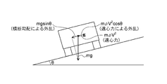
- FIG. 14 is a diagram schematically illustrating disturbance due to a transverse gradient and disturbance due to centrifugal force acting on a vehicle according to a fourth embodiment of the present invention.
- the vehicle is provided with a vehicle speed sensor 8, a yaw rate sensor 9, and a lateral acceleration sensor 10.
- the vehicle speed sensor 8 detects a vehicle speed that is the traveling speed of the vehicle.
- the yaw rate sensor 9 detects a yaw rate corresponding to the rotational angular velocity of the vehicle.
- the lateral acceleration sensor 10 detects a lateral acceleration of the vehicle.
- the switching unit 205 can switch the cutoff frequency of the low-pass filter 20 between the first cutoff frequency fc_A and the second cutoff frequency fc_B.
- the delay unit 207 outputs the previous value of the second assist amount to the adding unit 206 and the subtracting unit 201.
- z indicates z conversion
- 1 / z indicates the previous value.
- step S2 the crossing gradient estimator 18 estimates the crossing gradient using the vehicle speed, the yaw rate, and the lateral acceleration acquired in step S1. Thereafter, the process proceeds to step S3.
- the motor is configured to estimate the traverse gradient of the road on which the vehicle travels and generate the steering assist torque in consideration of the second assist amount based on the estimated traverse gradient
- the steering of the driver can be assisted in response to the change in the gradient.
- the change in the assist amount is adjusted by using a low-pass filter having a variable cutoff frequency
- the assist of the steering torque can be reduced by reducing the noise included in the estimated value of the traverse gradient. Interference can be suppressed.
- Embodiment 2 FIG.
- a description will be given of a steering control device 12 configured to include a processor 24 and an assist amount corrector 22 in the configuration of the first embodiment.
- the description of the same points as in the first embodiment is omitted, and the points different from the first embodiment will be mainly described.
- the processor 24 may be configured to perform one of the rate limiter process and the dead zone process on the cross slope input from the cross gradient estimator 18.
- the assist amount corrector 22 shown in FIG. 8 includes an output unit 221a, an output unit 222a, a switching unit 223a, and a multiplication unit 224a.
Abstract
This steering control system comprises a transverse gradient estimator that estimates the transverse gradient of a road surface, an assist amount calculator that calculates a first assist amount on the basis of the estimated transverse gradient, a low pass filter that outputs as a second assist amount the first assist amount after a low pass filter process has been performed on the calculated first assist amount, and a motor controller that uses the outputted second assist amount to control a motor. The low pass filter, depending on whether the second assist amount increases or the second assist amount is decreasing, switches a cutoff frequency of the low pass filter between a first cutoff frequency and a second cutoff frequency set to a higher value than the first cutoff frequency.
Description
本発明は、操舵アシストトルクを発生させるモータを制御する操舵制御装置に関する。
The present invention relates to a steering control device that controls a motor that generates a steering assist torque.
従来において、横断勾配路を走行する車両の偏向を抑制するように運転者の操舵をアシストする技術が提案されている(例えば、特許文献1参照)。具体的には、特許文献1に記載の従来技術は、横断勾配による外乱と、横風等に起因した横方向外乱とを推定し、その推定結果に基づいて、横方向外乱を抑制するように操舵アシストトルクを制御するよう構成されている。
Conventionally, there has been proposed a technique of assisting a driver in steering so as to suppress the deflection of a vehicle traveling on a cross-grade road (for example, see Patent Document 1). Specifically, the prior art described in Patent Document 1 estimates disturbance due to a cross slope and lateral disturbance due to a cross wind or the like, and performs steering to suppress the lateral disturbance based on the estimation result. It is configured to control the assist torque.
ここで、特許文献1に記載に従来技術では、車両が走行する路面の横断勾配による外乱が推定されるので、横断勾配の変化に対応して運転者の操舵をアシストすることが可能である。しかしながら、その推定に含まれるノイズが影響して、操舵トルクのアシストが運転者の操舵と干渉する可能性がある。
Here, according to the related art described in Patent Literature 1, disturbance due to the cross slope of the road surface on which the vehicle travels is estimated, and therefore, it is possible to assist the driver in steering in accordance with the change in the cross slope. However, there is a possibility that the assist of the steering torque interferes with the steering of the driver due to the noise included in the estimation.
本発明は、上述のような課題を解決するためになされたものであり、車両が走行する路面の横断勾配の変化に対応して運転者の操舵をアシストしつつ、操舵トルクのアシストが運転者の操舵と干渉することを抑制することができる操舵制御装置を得ることを目的とする。
The present invention has been made to solve the above-described problems, and assists the driver's steering in response to a change in the transverse gradient of a road surface on which a vehicle travels, and assists the driver in steering torque. It is an object of the present invention to obtain a steering control device capable of suppressing interference with the steering of the vehicle.
本発明における操舵制御装置は、車両が走行する路面の横断勾配を推定する横断勾配推定器と、横断勾配推定器によって推定された横断勾配に基づいて第1アシスト量を演算するアシスト量演算器と、アシスト量演算器によって演算された第1アシスト量に対して、ローパスフィルタ処理を施し、ローパスフィルタ処理後の第1アシスト量を、第2アシスト量として出力するローパスフィルタと、ローパスフィルタによって出力される第2アシスト量を用いて、操舵アシストトルクを発生させるモータを制御するモータ制御器と、を備え、ローパスフィルタは、第2アシスト量が増加変化する場合と、第2アシスト量が減少変化する場合とに応じて、ローパスフィルタのカットオフ周波数を、第1カットオフ周波数と、第1カットオフ周波数よりも高い値に設定される第2カットオフ周波数との間で切り替えるものである。
A steering control device according to the present invention includes a cross slope estimator that estimates a cross slope of a road surface on which a vehicle travels, an assist amount calculator that calculates a first assist amount based on the cross slope estimated by the cross slope estimator. A low-pass filter process is performed on the first assist amount calculated by the assist amount calculator, and a low-pass filter that outputs the first assist amount after the low-pass filter process as a second assist amount; And a motor controller that controls a motor that generates a steering assist torque using the second assist amount. The low-pass filter includes a case where the second assist amount increases and a case where the second assist amount decreases. Depending on the case, the cut-off frequency of the low-pass filter is changed to the first cut-off frequency and the first cut-off frequency. Is intended to switch between the second cut-off frequency is set to a value higher than.
本発明によれば、車両が走行する路面の横断勾配の変化に対応して運転者の操舵をアシストしつつ、操舵トルクのアシストが運転者の操舵と干渉することを抑制することができる操舵制御装置を得ることができる。
ADVANTAGE OF THE INVENTION According to this invention, the steering control which can suppress the assist of a steering torque from interfering with the driver's steering while assisting the driver's steering in response to the change of the transverse gradient of the road surface on which the vehicle travels is provided. A device can be obtained.
以下、本発明による操舵制御装置を、好適な実施の形態にしたがって図面を用いて説明する。なお、図面の説明においては、同一部分または相当部分には同一符号を付し、重複する説明を省略する。
Hereinafter, a steering control device according to the present invention will be described with reference to the drawings according to a preferred embodiment. In the description of the drawings, the same parts or corresponding parts will be denoted by the same reference characters, without redundant description.
実施の形態1.
図1は、本発明の実施の形態1における操舵制御装置12とその周辺装置の構成を示す図である。Embodiment 1 FIG.
FIG. 1 is a diagram showing a configuration of asteering control device 12 and peripheral devices according to Embodiment 1 of the present invention.
図1は、本発明の実施の形態1における操舵制御装置12とその周辺装置の構成を示す図である。
FIG. 1 is a diagram showing a configuration of a
図1において、自動車などの車両のステアリング機構は、ハンドル1とステアリング軸2とを備える。車両の左右の転舵輪3は、車両を運転する運転者がハンドル1を操作することによって回転するステアリング軸2の回転に応じて転舵される。
In FIG. 1, the steering mechanism of a vehicle such as an automobile includes a steering wheel 1 and a steering shaft 2. The steered wheels 3 on the left and right sides of the vehicle are steered according to the rotation of a steering shaft 2 that is rotated by the driver operating the vehicle operating the steering wheel 1.
ステアリング軸2には、操舵トルクセンサ4が設けられている。操舵トルクセンサ4は、運転者がハンドル1を操作することでハンドル1を介してステアリング軸2に作用する操舵トルクを検出する。
A steering torque sensor 4 is provided on the steering shaft 2. The steering torque sensor 4 detects a steering torque acting on the steering shaft 2 via the steering wheel 1 when the driver operates the steering wheel 1.
モータ5は、減速機構6を介してステアリング軸2に連結されている。モータ5は、後述する操舵制御装置12によってモータ5に流れる電流が制御されることで、ステアリング軸2に付与する操舵アシストトルクを発生させる。これにより、運転者の操舵をアシストすることが可能になる。
The motor 5 is connected to the steering shaft 2 via the speed reduction mechanism 6. The motor 5 generates a steering assist torque to be applied to the steering shaft 2 by controlling a current flowing through the motor 5 by a steering control device 12 described later. This makes it possible to assist the driver in steering.
モータ回転角度センサ7は、モータ5の回転角度を検出する。ハンドル1の操舵速度は、モータ回転角度センサ7によって検出されるモータ5の回転角度の微分値から演算される。電流センサ11は、モータ5に流れる電流を検出する。
The motor rotation angle sensor 7 detects the rotation angle of the motor 5. The steering speed of the steering wheel 1 is calculated from the differential value of the rotation angle of the motor 5 detected by the motor rotation angle sensor 7. The current sensor 11 detects a current flowing through the motor 5.
車両には、車速センサ8、ヨーレートセンサ9および横加速度センサ10が設けられている。車速センサ8は、車両の走行速度である車速を検出する。ヨーレートセンサ9は、車両の回転角速度に相当するヨーレートを検出する。横加速度センサ10は、車両の横加速度を検出する。
The vehicle is provided with a vehicle speed sensor 8, a yaw rate sensor 9, and a lateral acceleration sensor 10. The vehicle speed sensor 8 detects a vehicle speed that is the traveling speed of the vehicle. The yaw rate sensor 9 detects a yaw rate corresponding to the rotational angular velocity of the vehicle. The lateral acceleration sensor 10 detects a lateral acceleration of the vehicle.
操舵制御装置12は、上述した各種センサの検出結果を取得し、その取得結果に基づいて、操舵アシストトルクの目標値である目標トルクを演算する。操舵制御装置12は、演算した目標トルクと、モータ5が発生させる操舵アシストトルクとが一致するように、モータ5を制御する。
The steering control device 12 acquires the detection results of the various sensors described above, and calculates a target torque, which is a target value of the steering assist torque, based on the acquired results. The steering control device 12 controls the motor 5 so that the calculated target torque matches the steering assist torque generated by the motor 5.
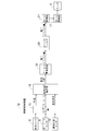
操舵制御装置12は、例えば、図1に示すハードウェア構成によって実現される。すなわち、操舵制御装置12は、各種センサの検出結果を取得するインターフェース部13と、演算処理を実行するマイクロコンピュータと、モータ5に電流を供給することでモータ5を駆動するモータ駆動器17とによって実現される。マイクロコンピュータは、CPU(Central Processing Unit)14と、ROM(Read Only Memory)15と、RAM(Random Access Memory)16とを含んで構成される。
The steering control device 12 is realized, for example, by the hardware configuration shown in FIG. That is, the steering control device 12 includes an interface unit 13 that acquires detection results of various sensors, a microcomputer that executes arithmetic processing, and a motor driver 17 that drives the motor 5 by supplying current to the motor 5. Is achieved. The microcomputer includes a CPU (Central Processing Unit) 14, a ROM (Read Only Memory) 15, and a RAM (Random Access Memory) 16.
次に、操舵制御装置12の機能構成について、図2を参照しながら説明する。図2は、本発明の実施の形態1における操舵制御装置12の構成を示すブロック図である。
Next, the functional configuration of the steering control device 12 will be described with reference to FIG. FIG. 2 is a block diagram illustrating a configuration of the steering control device 12 according to Embodiment 1 of the present invention.
図2において、操舵制御装置12は、インターフェース部13、横断勾配推定器18、アシスト量演算器19、ローパスフィルタ20、モータ制御器21およびモータ駆動器17を備える。
In FIG. 2, the steering control device 12 includes an interface unit 13, a traverse gradient estimator 18, an assist amount calculator 19, a low-pass filter 20, a motor controller 21, and a motor driver 17.
横断勾配推定器18は、インターフェース部13を介して、車速センサ8から車速を取得し、ヨーレートセンサ9からヨーレートを取得し、横加速度センサ10から横加速度を取得する。横断勾配推定器18は、取得した車速、ヨーレートおよび横加速度に基づいて、横断勾配を推定し、その横断勾配をアシスト量演算器19に出力する。
The crossing gradient estimator 18 acquires the vehicle speed from the vehicle speed sensor 8, acquires the yaw rate from the yaw rate sensor 9, and acquires the lateral acceleration from the lateral acceleration sensor 10 via the interface unit 13. The traverse gradient estimator 18 estimates the traverse gradient based on the acquired vehicle speed, yaw rate, and lateral acceleration, and outputs the traverse gradient to the assist amount calculator 19.
ここで、横断勾配推定器18が横断勾配を推定する方法の例について、図3を参照しながら説明する。図3は、本発明の実施の形態1における車両に作用する横断勾配による外乱を模式的に示す図である。ただし、mは車両の質量を示し、gは重力加速度を示し、θは車両が走行する路面の横断勾配を示す。
Here, an example of a method of estimating the cross slope by the cross slope estimator 18 will be described with reference to FIG. FIG. 3 is a diagram schematically showing a disturbance due to a transverse gradient acting on the vehicle in the first embodiment of the present invention. Here, m indicates the mass of the vehicle, g indicates the gravitational acceleration, and θ indicates the transverse gradient of the road surface on which the vehicle runs.
図3に示すように、車両が走行する路面の傾きが横断勾配θに相当する。横断勾配推定器18は、車速センサ8から取得した車速Vと、ヨーレートセンサ9から取得したヨーレートγと、横加速度センサ10から取得した横加速度Gyとを用いて、以下の式(1)に従って横断勾配θを演算して推定する。
θ=arcsin((dvy/dt+V・γ-Gy)/g)
≒arcsin((V・γ-Gy)/g) (1) As shown in FIG. 3, the inclination of the road surface on which the vehicle travels corresponds to the transverse gradient θ. Thetransverse gradient estimator 18 uses the vehicle speed V acquired from the vehicle speed sensor 8, the yaw rate γ acquired from the yaw rate sensor 9, and the lateral acceleration Gy acquired from the lateral acceleration sensor 10 to traverse according to the following equation (1). The gradient θ is calculated and estimated.
θ = arcsin ((dvy / dt + V · γ-Gy) / g)
≒ arcsin ((V · γ-Gy) / g) (1)
θ=arcsin((dvy/dt+V・γ-Gy)/g)
≒arcsin((V・γ-Gy)/g) (1) As shown in FIG. 3, the inclination of the road surface on which the vehicle travels corresponds to the transverse gradient θ. The
θ = arcsin ((dvy / dt + V · γ-Gy) / g)
≒ arcsin ((V · γ-Gy) / g) (1)
ただし、式(1)において、dvy/dtは車両の横速度の時間変化を示し、ここでは、車両が直進走行に近い定常走行をしていると考え、dvy/dt=0としている。
In the equation (1), however, dvy / dt indicates a temporal change in the lateral speed of the vehicle. Here, it is assumed that the vehicle is traveling in a steady state close to straight traveling, and dvy / dt = 0.
なお、横断勾配推定器18が横断勾配を推定する方法は、上述した方法に限定されない。例えば、横断勾配推定器18は、特許文献1に記載の公知の方法を用いて、横断勾配を推定するように構成されていてもよい。また、横断勾配推定器18は、車両が走行する路面に関する情報を地図情報として予め記憶し、車両の走行地点に応じた横断勾配を、地図情報から求めるように構成されていてもよい。
The method of estimating the cross slope by the cross slope estimator 18 is not limited to the above-described method. For example, the cross gradient estimator 18 may be configured to estimate the cross gradient using a known method described in Patent Document 1. Further, the crossing gradient estimator 18 may be configured to store information on the road surface on which the vehicle travels as map information in advance, and obtain a crossing gradient corresponding to the traveling point of the vehicle from the map information.
このように、横断勾配推定器18は、車両が走行する路面の横断勾配を推定するように構成されている。具体例として、横断勾配推定器18は、車速センサ8によって検出された車速と、ヨーレートセンサ9によって検出されたヨーレートと、横加速度センサ10によって検出された横加速度に基づいて、横断勾配を推定するように構成されている。
As described above, the crossing gradient estimator 18 is configured to estimate the crossing gradient of the road surface on which the vehicle travels. As a specific example, the crossing gradient estimator 18 estimates the crossing gradient based on the vehicle speed detected by the vehicle speed sensor 8, the yaw rate detected by the yaw rate sensor 9, and the lateral acceleration detected by the lateral acceleration sensor 10. It is configured as follows.
アシスト量演算器19は、横断勾配推定器18から入力された横断勾配に基づいて、第1アシスト量を演算し、その第1アシスト量をローパスフィルタ20に出力する。
The assist amount calculator 19 calculates a first assist amount based on the transverse gradient input from the transverse gradient estimator 18, and outputs the first assist amount to the low-pass filter 20.
ここで、アシスト量演算器19が第1アシスト量を演算する方法の例について説明する。
Here, an example of a method in which the assist amount calculator 19 calculates the first assist amount will be described.
車両運動モデルで一般的に用いられている2輪モデルにて、車両が直進走行していることを想定する。
す る It is assumed that the vehicle is running straight in a two-wheel model generally used in a vehicle motion model.
この場合、フロントタイヤ2輪に発生する横力2Fyは、以下の式(2)に従って求められる。
In this case, the lateral force 2Fy generated in the two front tires is obtained according to the following equation (2).
2Fy=-lr/(lf+lr)mgsinθ (2)
{2Fy = -lr / (lf + lr) mgsinθ} (2)
ただし、式(2)において、lfは、車両重心から前輪軸までの距離を示し、lrは、車両重心から後輪軸までの距離を示す。
In the equation (2), if indicates the distance from the vehicle center of gravity to the front wheel axle, and lr indicates the distance from the vehicle center of gravity to the rear wheel axle.
ここで、車両のキャスタートレールをLc[m]とし、ニューマチックトレールをLp[m]とし、オーバーオールステアリングギア比をGrpとすると、ステアリング軸換算の横断勾配による外乱トルクTcantは、以下の式(3)に従って求められる。
Here, assuming that the caster rail of the vehicle is Lc [m], the pneumatic trail is Lp [m], and the overall steering gear ratio is Grp, the disturbance torque Tcant due to the transverse gradient converted into the steering axis is represented by the following equation (3). ).
Tcant=2Fy×(Lc+Lp)×Grp (3)
{Tcant = 2Fy × (Lc + Lp) × Grp} (3)
したがって、補償トルクTcomp1によって、外乱トルクTcantがキャンセルされるようにするため、補償トルクTcomp1は、以下の式(4)に従って求められる。補償トルクTcomp1は、横断勾配θにほぼ比例した補償量となる。補償トルクTcomp1が第1アシスト量に相当する。
Therefore, in order that the disturbance torque Tcant is canceled by the compensation torque Tcomp1, the compensation torque Tcomp1 is obtained according to the following equation (4). The compensation torque Tcomp1 is a compensation amount substantially proportional to the transverse gradient θ. The compensation torque Tcomp1 corresponds to the first assist amount.
Tcomp1=-Tcant (4)
{Tcomp1 = -Tcant} (4)
アシスト量演算器19は、横断勾配推定器18から入力された横断勾配θを用いて、上述の式(2)、式(3)および式(4)に従って第1アシスト量を演算する。
The assist amount calculator 19 calculates the first assist amount according to the above equations (2), (3) and (4) using the transverse gradient θ input from the transverse gradient estimator 18.
なお、アシスト量演算器19が第1アシスト量を演算する方法は、上述した方法に限定されない。例えば、第1アシスト量は、横断勾配にほぼ比例した補償量になることを利用して、実車で適合を行うことによって求められてもよい。
The method by which the assist amount calculator 19 calculates the first assist amount is not limited to the method described above. For example, the first assist amount may be determined by performing the adaptation with an actual vehicle, using the fact that the amount of compensation becomes substantially proportional to the transverse gradient.
なお、外乱トルクTcantが完全にキャンセルされるようにする必要がない場合には、式(4)の右辺の項に1よりも小さいゲインを乗算することで、補償トルクTcomp1を補正してもよい。これにより、運転者の負担を軽減しつつ、横断勾配路を走行している感覚を運転者に伝えることが可能となる。また、式(4)の右辺の項に車速に応じて変化するゲインを乗算することで、補償トルクTcomp1を補正してもよい。これにより、車速に応じて第1アシスト量を調整することが可能となる。
When it is not necessary to completely cancel the disturbance torque Tcant, the compensation torque Tcomp1 may be corrected by multiplying the term on the right side of the equation (4) by a gain smaller than 1. . As a result, it is possible to convey to the driver the feeling of traveling on a cross slope while reducing the burden on the driver. Further, the compensation torque Tcomp1 may be corrected by multiplying the term on the right side of the equation (4) by a gain that changes according to the vehicle speed. Thus, the first assist amount can be adjusted according to the vehicle speed.
このように、アシスト量演算器19は、横断勾配推定器18によって推定された横断勾配に基づいて第1アシスト量を演算するように構成されている。
As described above, the assist amount calculator 19 is configured to calculate the first assist amount based on the transverse gradient estimated by the transverse gradient estimator 18.
ローパスフィルタ20は、アシスト量演算器19によって演算された第1アシスト量に対して、ローパスフィルタ処理を施し、ローパスフィルタ処理後の第1アシスト量を、第2アシスト量として、モータ制御器21に出力する。
The low-pass filter 20 performs a low-pass filter process on the first assist amount calculated by the assist amount calculator 19, and sets the first assist amount after the low-pass filter process as a second assist amount to the motor controller 21. Output.
ここで、ローパスフィルタ20の構成について、図4を参照しながら説明する。図4は、本発明の実施の形態1におけるローパスフィルタ20の構成を示すブロック図である。
Here, the configuration of the low-pass filter 20 will be described with reference to FIG. FIG. 4 is a block diagram showing a configuration of the low-pass filter 20 according to Embodiment 1 of the present invention.
図4において、ローパスフィルタ20は、減算部201、ゲイン部202、ゲイン部203、判定部204、切り替え部205、加算部206および遅延部207を備える。
4, the low-pass filter 20 includes a subtraction unit 201, a gain unit 202, a gain unit 203, a determination unit 204, a switching unit 205, an addition unit 206, and a delay unit 207.
減算部201は、アシスト量演算器19の出力値である第1アシスト量から、遅延部207の出力値である第2アシスト量の前回値を減算することで得られる値をゲイン部202およびゲイン部203に出力する。
The subtraction unit 201 subtracts the value obtained by subtracting the previous value of the second assist amount, which is the output value of the delay unit 207, from the first assist amount, which is the output value of the assist amount calculator 19, into the gain unit 202 and the gain. Output to the unit 203.
ゲイン部202は、減算部201の出力値に、ゲインである2πTsfc_Aを乗算することで得られる値を切り替え部205に出力する。ゲイン部203は、減算部201の出力値に、ゲインである2πTsfc_Bを乗算することで得られる値を切り替え部205に出力する。
Gain section 202 outputs to switching section 205 a value obtained by multiplying the output value of subtraction section 201 by 2πTsfc_A which is a gain. Gain section 203 outputs a value obtained by multiplying the output value of subtraction section 201 by 2πTsfc_B, which is a gain, to switching section 205.
上述のパラメータに関して、fc_Aは、ローパスフィルタ20に設定される第1カットオフ周波数を示し、fc_Bは、ローパスフィルタ20に設定される第2カットオフ周波数を示す。第2カットオフ周波数fc_Bは、第1カットオフ周波数fc_Aよりも高い値に設定される。Tsは、ローパスフィルタ20の制御周期を示す。
に 関 し て Regarding the above parameters, fc_A indicates a first cutoff frequency set in the low-pass filter 20, and fc_B indicates a second cutoff frequency set in the low-pass filter 20. The second cutoff frequency fc_B is set to a value higher than the first cutoff frequency fc_A. Ts indicates a control cycle of the low-pass filter 20.
判定部204は、アシスト量演算器19の出力値である第1アシスト量と、遅延部207の出力値である第2アシスト量の前回値とを比較し、第1アシスト量が第2アシスト量の前回値よりも大きいか否かを判定する。判定部204は、その判定結果を切り替え部205に出力する。
The determination unit 204 compares the first assist amount that is the output value of the assist amount calculator 19 with the previous value of the second assist amount that is the output value of the delay unit 207, and determines that the first assist amount is the second assist amount. Is determined to be greater than the previous value. The determination unit 204 outputs the determination result to the switching unit 205.
切り替え部205は、判定部204の出力値である判定結果に基づいて、ゲイン部202の出力値およびゲイン部203の出力値のいずれかを選択し、選択した方の値を加算部206に出力する。
The switching unit 205 selects one of the output value of the gain unit 202 and the output value of the gain unit 203 based on the determination result that is the output value of the determination unit 204, and outputs the selected value to the addition unit 206. I do.
切り替え部205は、判定部204によって第1アシスト量が第2アシスト量の前回値よりも大きいと判定された場合には、ゲイン部202の出力値を加算部206に出力する。一方、切り替え部205は、判定部204によって第1アシスト量が第2アシスト量の前回値よりも小さいと判定された場合には、ゲイン部203の出力値を加算部206に出力する。
The switching unit 205 outputs the output value of the gain unit 202 to the addition unit 206 when the determination unit 204 determines that the first assist amount is larger than the previous value of the second assist amount. On the other hand, when the determining unit 204 determines that the first assist amount is smaller than the previous value of the second assist amount, the switching unit 205 outputs the output value of the gain unit 203 to the adding unit 206.
このように、切り替え部205によって、ローパスフィルタ20のカットオフ周波数を、第1カットオフ周波数fc_Aと、第2カットオフ周波数fc_Bとの間で切り替え可能となる。
As described above, the switching unit 205 can switch the cutoff frequency of the low-pass filter 20 between the first cutoff frequency fc_A and the second cutoff frequency fc_B.
第1アシスト量が第2アシスト量の前回値よりも大きい場合、すなわち、第2アシスト量が増加変化する場合には、ローパスフィルタ20のカットオフ周波数は、第1カットオフ周波数fc_Aに設定される。一方、第1アシスト量が第2アシスト量の前回値よりも小さい場合、すなわち、第2アシスト量が減少変化する場合には、ローパスフィルタ20のカットオフ周波数は、第2カットオフ周波数fc_Bに設定される。
When the first assist amount is larger than the previous value of the second assist amount, that is, when the second assist amount increases and changes, the cutoff frequency of the low-pass filter 20 is set to the first cutoff frequency fc_A. . On the other hand, when the first assist amount is smaller than the previous value of the second assist amount, that is, when the second assist amount decreases, the cutoff frequency of the low-pass filter 20 is set to the second cutoff frequency fc_B. Is done.
加算部206は、切り替え部205の出力値と、遅延部207の出力値である第2アシスト量の前回値とを加算することで得られる値を、第2アシスト量として出力する。
The addition unit 206 outputs a value obtained by adding the output value of the switching unit 205 and the previous value of the second assist amount, which is the output value of the delay unit 207, as the second assist amount.
遅延部207は、第2アシスト量の前回値を、加算部206および減算部201に出力する。ここで、zはz変換を示し、1/zは前回値を示す。
The delay unit 207 outputs the previous value of the second assist amount to the adding unit 206 and the subtracting unit 201. Here, z indicates z conversion, and 1 / z indicates the previous value.
このように、ローパスフィルタ20は、第2アシスト量が増加変化する場合と、第2アシスト量が減少変化する場合とに応じて、ローパスフィルタ20のカットオフ周波数を、第1カットオフ周波数fc_Aと、第2カットオフ周波数fc_Bとの間で切り替える。
As described above, the low-pass filter 20 sets the cut-off frequency of the low-pass filter 20 to the first cut-off frequency fc_A according to the case where the second assist amount increases and the case where the second assist amount decreases. , And the second cutoff frequency fc_B.
ローパスフィルタ20は、第2アシスト量が増加変化する場合には、ローパスフィルタ20のカットオフ周波数を第1カットオフ周波数fc_Aにする。また、ローパスフィルタ20は、第2アシスト量が減少変化する場合には、ローパスフィルタ20のカットオフ周波数を第2カットオフ周波数fc_Bにする。
(4) When the second assist amount increases and changes, the low-pass filter 20 sets the cut-off frequency of the low-pass filter 20 to the first cut-off frequency fc_A. Further, when the second assist amount decreases and changes, the low-pass filter 20 sets the cut-off frequency of the low-pass filter 20 to the second cut-off frequency fc_B.
次に、第1カットオフ周波数fc_Aおよび第2カットオフ周波数fc_Bの設定について説明する。上述したように、第2カットオフ周波数fc_Bは、第1カットオフ周波数fc_Aよりも高い値に設定される。例えば、第1カットオフ周波数fc_Aおよび第2カットオフ周波数fc_Bについて、fc_A=1[Hz]となり、fc_B=3[Hz]となるように設定される。
Next, the setting of the first cutoff frequency fc_A and the second cutoff frequency fc_B will be described. As described above, the second cutoff frequency fc_B is set to a value higher than the first cutoff frequency fc_A. For example, the first cutoff frequency fc_A and the second cutoff frequency fc_B are set so that fc_A = 1 [Hz] and fc_B = 3 [Hz].
上述したように、第2アシスト量が増加変化する場合には、ローパスフィルタ20のカットオフ周波数が第1カットオフ周波数fc_Aに設定される。そのため、第2アシスト量は、緩慢に増加する。一方、第2アシスト量が減少変化する場合には、ローパスフィルタ20のカットオフ周波数が第2カットオフ周波数fc_Bに設定される。そのため、第2アシスト量は、急激に減少する。
As described above, when the second assist amount increases, the cutoff frequency of the low-pass filter 20 is set to the first cutoff frequency fc_A. Therefore, the second assist amount increases slowly. On the other hand, when the second assist amount decreases, the cutoff frequency of the low-pass filter 20 is set to the second cutoff frequency fc_B. Therefore, the second assist amount sharply decreases.
ここで、第2カットオフ周波数fc_Bの値が大きく設定されるほど、第2アシスト量は、より急激に減少する。第2アシスト量の急激な減少変化は、第2アシスト量が不連続に変化しているように運転者に伝わり、その結果、運転者が違和感を持つ。そのため、第2カットオフ周波数fc_Bは、例えば、5Hz以下に設定されることが望ましい。
Here, the larger the value of the second cutoff frequency fc_B is set, the more rapidly the second assist amount decreases. The sudden decrease in the second assist amount is transmitted to the driver as if the second assist amount is discontinuously changing. As a result, the driver feels strange. Therefore, it is desirable that the second cutoff frequency fc_B is set to, for example, 5 Hz or less.
このようなローパスフィルタ20の構成によって、横断勾配推定器18によって推定される横断勾配の推定値に含まれるノイズを低減することができる。なお、横断勾配の推定値に含まれるノイズの周波数は、例えば、10Hz以上である。
With such a configuration of the low-pass filter 20, noise included in the estimated value of the cross gradient estimated by the cross gradient estimator 18 can be reduced. The frequency of the noise included in the estimated value of the cross gradient is, for example, 10 Hz or more.
また、このようなローパスフィルタ20の構成において、第1カットオフ周波数fc_Aを第2カットオフ周波数fc_Bよりも低い値にすることによって、横断勾配に対応して操舵アシストトルクをより滑らかに出力することができる。その結果、操舵トルクのアシストが運転者の操舵と干渉することを抑制することが可能となる。
Further, in such a configuration of the low-pass filter 20, by setting the first cutoff frequency fc_A to a value lower than the second cutoff frequency fc_B, it is possible to more smoothly output the steering assist torque corresponding to the transverse gradient. Can be. As a result, it is possible to suppress the steering torque assist from interfering with the driver's steering.
比較例として、ローパスフィルタ20のカットオフ周波数が固定となる構成である場合、横断勾配がゼロになっても、第2アシスト量がすぐに減少せず、操舵トルクのアシストが継続され、その結果、操舵トルクのアシストが運転者の操舵と干渉する可能性がある。
As a comparative example, when the cut-off frequency of the low-pass filter 20 is fixed, the second assist amount does not immediately decrease even if the transverse gradient becomes zero, and the assist of the steering torque is continued. The steering torque assist may interfere with the driver's steering.
これに対して、実施の形態1のようにローパスフィルタ20のカットオフ周波数が可変となる構成によって、第2アシスト量が速やかに減少する。したがって、上述したように、横断勾配の推定値に含まれるノイズを低減しつつ、操舵トルクのアシストが運転者の操舵と干渉することを抑制することが可能となる。
On the other hand, with the configuration in which the cutoff frequency of the low-pass filter 20 is variable as in the first embodiment, the second assist amount is quickly reduced. Therefore, as described above, it is possible to suppress the assist of the steering torque from interfering with the driver's steering while reducing the noise included in the estimated value of the transverse gradient.
モータ制御器21は、ローパスフィルタ20によって出力される第2アシスト量を用いて、操舵アシストトルクを発生させるモータ5を制御する。具体的には、モータ制御器21は、ローパスフィルタ20から入力された第2アシスト量を、目標トルクとし、その目標トルクと、モータ5が発生させる操舵アシストトルクとが一致するようにモータ駆動器17にモータ5を駆動させる。なお、モータ制御器21は、第2アシスト量と、その他公知の操舵制御が適用される場合に演算されるアシスト量とを足し合わせることで得られる値を、目標トルクとするように構成されていてもよい。
The motor controller 21 controls the motor 5 that generates the steering assist torque by using the second assist amount output by the low-pass filter 20. Specifically, the motor controller 21 uses the second assist amount input from the low-pass filter 20 as a target torque, and sets the motor driver so that the target torque matches the steering assist torque generated by the motor 5. 17 drives the motor 5. The motor controller 21 is configured to set a value obtained by adding the second assist amount and an assist amount calculated when other known steering control is applied as the target torque. You may.
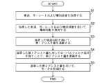
次に、操舵制御装置12の動作について、図5を参照しながら説明する。図5は、本発明の実施の形態1における操舵制御装置12の一連の動作を示すフローチャートである。図5に示すフローチャートの処理は、例えば、予め設定される制御周期で繰り返し実行される。
Next, the operation of the steering control device 12 will be described with reference to FIG. FIG. 5 is a flowchart showing a series of operations of the steering control device 12 according to Embodiment 1 of the present invention. The process of the flowchart shown in FIG. 5 is repeatedly executed, for example, at a preset control cycle.
ステップS1において、横断勾配推定器18は、インターフェース部13を介して、車速センサ8から車速を取得し、ヨーレートセンサ9からヨーレートを取得し、横加速度センサ10から横加速度を取得する。その後、処理がステップS2へと進む。
In step S <b> 1, the crossing gradient estimator 18 acquires the vehicle speed from the vehicle speed sensor 8, acquires the yaw rate from the yaw rate sensor 9, and acquires the lateral acceleration from the lateral acceleration sensor 10 via the interface unit 13. Thereafter, the process proceeds to step S2.
ステップS2において、横断勾配推定器18は、ステップS1で取得された車速、ヨーレートおよび横加速度を用いて、横断勾配を推定する。その後、処理がステップS3へと進む。
In step S2, the crossing gradient estimator 18 estimates the crossing gradient using the vehicle speed, the yaw rate, and the lateral acceleration acquired in step S1. Thereafter, the process proceeds to step S3.
ステップS3において、アシスト量演算器19は、ステップS2で推定された横断勾配を用いて、第1アシスト量を演算する。その後、処理がステップS4へと進む。
In step S3, the assist amount calculator 19 calculates the first assist amount by using the transverse gradient estimated in step S2. Thereafter, the process proceeds to step S4.
ステップS4において、ローパスフィルタ20は、ステップS3で演算された第1アシスト量に対してローパスフィルタ処理を施すことで、第2アシスト量を演算する。その後、処理がステップS5へと進む。
In step S4, the low-pass filter 20 performs a low-pass filter process on the first assist amount calculated in step S3 to calculate a second assist amount. Thereafter, the process proceeds to step S5.
ステップS5において、モータ制御器21は、ステップS4で演算された第2アシスト量を用いて、モータ5を制御する。具体的には、モータ制御器21は、ステップS4で演算された第2アシスト量を用いて、モータ5に流れるモータ電流を制御する。これにより、モータ5は、モータ電流に応じた操舵アシストトルクを発生させ、横断勾配路を走行するために必要な運転者の操舵をアシストする。その後、処理が終了となる。
In step S5, the motor controller 21 controls the motor 5 using the second assist amount calculated in step S4. Specifically, the motor controller 21 controls the motor current flowing to the motor 5 using the second assist amount calculated in step S4. As a result, the motor 5 generates a steering assist torque corresponding to the motor current, and assists the driver to perform steering necessary for traveling on the cross slope. Thereafter, the process ends.
以上、本実施の形態1によれば、操舵制御装置は、路面の横断勾配を推定する横断勾配推定器と、横断勾配推定器によって推定された横断勾配に基づいて第1アシスト量を演算するアシスト量演算器と、アシスト量演算器によって演算された第1アシスト量に対して、ローパスフィルタ処理を施すことで、ローパスフィルタ処理後の第1アシスト量を、第2アシスト量として出力するローパスフィルタと、ローパスフィルタによって出力される第2アシスト量を用いて、操舵アシストトルクを発生させるモータを制御するモータ制御器と、を備えて構成されている。
As described above, according to the first embodiment, the steering control device includes the cross slope estimator that estimates the cross slope of the road surface and the assist that calculates the first assist amount based on the cross slope estimated by the cross slope estimator. An amount calculator and a low-pass filter that outputs the first assist amount after the low-pass filter process as a second assist amount by performing a low-pass filter process on the first assist amount calculated by the assist amount calculator. And a motor controller that controls a motor that generates a steering assist torque using the second assist amount output by the low-pass filter.
また、ローパスフィルタは、第2アシスト量が増加変化する場合と、第2アシスト量が減少変化する場合とに応じて、ローパスフィルタのカットオフ周波数を、第1カットオフ周波数と、第1カットオフ周波数よりも高い値に設定される第2カットオフ周波数との間で切り替えるように構成されている。
Further, the low-pass filter changes the cut-off frequency of the low-pass filter according to a case where the second assist amount increases and a case where the second assist amount decreases and changes the first cut-off frequency and the first cut-off frequency. It is configured to switch between a second cutoff frequency set to a value higher than the frequency.
このように、車両が走行する路面の横断勾配を推定し、推定された横断勾配に基づいた第2アシスト量を加味した操舵アシストトルクをモータが発生させるように構成されているので、路面の横断勾配の変化に対応して運転者の操舵をアシストすることができる。また、カットオフ周波数が可変であるローパスフィルタが用いられることによって、アシスト量の変化が調整されるので、横断勾配の推定値に含まれるノイズを低減しつつ、操舵トルクのアシストが運転者の操舵と干渉することを抑制することが可能となる。
As described above, since the motor is configured to estimate the traverse gradient of the road on which the vehicle travels and generate the steering assist torque in consideration of the second assist amount based on the estimated traverse gradient, The steering of the driver can be assisted in response to the change in the gradient. In addition, since the change in the assist amount is adjusted by using a low-pass filter having a variable cutoff frequency, the assist of the steering torque can be reduced by reducing the noise included in the estimated value of the traverse gradient. Interference can be suppressed.
つまり、上述のように操舵制御装置を構成することで、路面の横断勾配の変化に対応して運転者の操舵をアシストしつつ、操舵トルクのアシストが運転者の操舵と干渉することを抑制することができる。
In other words, by configuring the steering control device as described above, the assist of the steering torque is prevented from interfering with the steering of the driver while assisting the steering of the driver in response to the change in the traverse gradient of the road surface. be able to.
実施の形態2.
本発明の実施の形態2では、先の実施の形態1の構成に対して、処理器24およびアシスト量補正器22を備えて構成されている操舵制御装置12について説明する。なお、実施の形態2では、先の実施の形態1と同様である点の説明を省略し、先の実施の形態1と異なる点を中心に説明する。Embodiment 2 FIG.
In a second embodiment of the present invention, a description will be given of asteering control device 12 configured to include a processor 24 and an assist amount corrector 22 in the configuration of the first embodiment. In the second embodiment, the description of the same points as in the first embodiment is omitted, and the points different from the first embodiment will be mainly described.
本発明の実施の形態2では、先の実施の形態1の構成に対して、処理器24およびアシスト量補正器22を備えて構成されている操舵制御装置12について説明する。なお、実施の形態2では、先の実施の形態1と同様である点の説明を省略し、先の実施の形態1と異なる点を中心に説明する。
In a second embodiment of the present invention, a description will be given of a
図6は、本発明の実施の形態2における操舵制御装置12の構成を示すブロック図である。図6において、操舵制御装置12は、インターフェース部13、横断勾配推定器18、処理器24、アシスト量演算器19、アシスト量補正器22、ローパスフィルタ20、モータ制御器21およびモータ駆動器17を備える。
FIG. 6 is a block diagram showing a configuration of the steering control device 12 according to Embodiment 2 of the present invention. 6, the steering control device 12 includes an interface unit 13, a transverse gradient estimator 18, a processor 24, an assist amount calculator 19, an assist amount corrector 22, a low-pass filter 20, a motor controller 21, and a motor driver 17. Prepare.
処理器24は、横断勾配推定器18によって推定された横断勾配に対して、後述するレートリミッタ処理および不感帯処理を施し、これらの処理後の横断勾配をアシスト量演算器19に出力する。アシスト量演算器19は、処理器24から入力された横断勾配を用いて、先の実施の形態1と同様に、第1アシスト量を演算する。
The processor 24 performs a rate limiter process and a dead zone process, which will be described later, on the transverse gradient estimated by the transverse gradient estimator 18, and outputs the processed transverse gradient to the assist amount calculator 19. The assist amount calculator 19 calculates the first assist amount using the transverse gradient input from the processor 24 in the same manner as in the first embodiment.
ここで、処理器24によって行われるレートリミッタ処理について説明する。通常、路面の横断勾配は、急激な変化を抑えるために、すりつけ部によって連続的に変化するようになっている。レートリミッタの閾値は、このすりつけ部相当の値に設定される。これにより、横断勾配推定器18によって推定される横断勾配の急激な変化をレートリミッタ処理によって制限することが可能となる。横断勾配の急激な変化は、車両が悪路等を走行した場合に生じる。
Here, the rate limiter process performed by the processor 24 will be described. Usually, the crossing slope of the road surface is continuously changed by the rubbing portion in order to suppress a sudden change. The threshold of the rate limiter is set to a value corresponding to the rubbing portion. As a result, it is possible to limit a rapid change in the cross slope estimated by the cross slope estimator 18 by the rate limiter processing. The abrupt change in the crossing gradient occurs when the vehicle travels on a rough road or the like.
このように、処理器24は、横断勾配推定器18によって推定された横断勾配に対してレートリミッタ処理を施すように構成されている。このような構成によって、路面の横断勾配の変化が法規で決まっており、推定された横断勾配の変化が、レートリミッタの閾値として設定する横断勾配の変化よりも大きい場合であっても、横断勾配の急激な変化を抑えることができる。これにより、アシスト量の急激な変化を抑制することができ、結果として、操舵トルクのアシストが運転者の操舵と干渉することを抑制することができる。
As described above, the processor 24 is configured to perform the rate limiter processing on the cross slope estimated by the cross slope estimator 18. With such a configuration, the change in the cross slope of the road surface is determined by regulation, and even if the estimated change in the cross slope is larger than the change in the cross slope set as the threshold of the rate limiter, Abrupt changes in the temperature can be suppressed. As a result, a rapid change in the assist amount can be suppressed, and as a result, it is possible to suppress the assist of the steering torque from interfering with the driver's steering.
続いて、処理器24によって行われる不感帯処理について説明する。不感帯処理によって、横断勾配の微小な変化に対するアシスト量の変化を抑制することができる。
Next, the dead zone process performed by the processor 24 will be described. By the dead zone processing, it is possible to suppress a change in the assist amount with respect to a minute change in the transverse gradient.
すなわち、横断勾配の微小な変化に対してアシスト量が変化する場合、運転者は、ハンドル中立付近にてハンドルの変動を感じてしまう。その結果、運転者が煩わしさを感じる可能性がある。これに対して、不感帯処理によって、運転者が煩わしさを感じることを抑制することができ、結果として、操舵トルクのアシストが運転者の操舵と干渉することを抑制することができる。
That is, when the assist amount changes in response to a small change in the transverse gradient, the driver feels a change in the steering wheel near the neutral position of the steering wheel. As a result, the driver may feel annoyed. On the other hand, by the dead zone processing, the driver can be prevented from feeling annoying, and as a result, the assist of the steering torque can be prevented from interfering with the steering of the driver.
なお、処理器24は、横断勾配推定器18から入力された横断勾配に対して、レートリミッタ処理および不感帯処理のいずれか一方の処理を施すように構成されていてもよい。
The processor 24 may be configured to perform one of the rate limiter process and the dead zone process on the cross slope input from the cross gradient estimator 18.
このように、処理器24は、横断勾配推定器18によって推定された横断勾配に対して、レートリミッタ処理および不感帯処理の少なくとも一方の処理を施すように構成されている。
As described above, the processor 24 is configured to perform at least one of the rate limiter process and the dead zone process on the cross slope estimated by the cross slope estimator 18.
アシスト量補正器22は、インターフェース部13を介して、操舵トルクセンサ4から操舵トルクを取得する。アシスト量補正器22は、ローパスフィルタ20から第2アシスト量の前回値を取得する。
The assist amount corrector 22 acquires the steering torque from the steering torque sensor 4 via the interface unit 13. The assist amount corrector 22 acquires the previous value of the second assist amount from the low-pass filter 20.
アシスト量補正器22は、取得した操舵トルクおよび第2アシスト量の前回値に基づいて、アシスト量演算器19によって演算された第1アシスト量を補正し、補正後の第1アシスト量をローパスフィルタ20に出力する。ローパスフィルタ20は、アシスト量補正器22から入力された第1アシスト量に対して、先の実施の形態1で説明したローパスフィルタ処理を施すことで、第2アシスト量を演算する。
The assist amount corrector 22 corrects the first assist amount calculated by the assist amount calculator 19 based on the obtained steering torque and the previous value of the second assist amount, and outputs the corrected first assist amount to a low-pass filter. 20. The low-pass filter 20 calculates the second assist amount by performing the low-pass filter processing described in the first embodiment on the first assist amount input from the assist amount corrector 22.
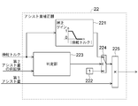
アシスト量補正器22の構成について、図7を参照しながら説明する。図7は、本発明の実施の形態2におけるアシスト量補正器22の構成を示すブロック図である。
The configuration of the assist amount corrector 22 will be described with reference to FIG. FIG. 7 is a block diagram showing a configuration of the assist amount corrector 22 according to Embodiment 2 of the present invention.
図7において、アシスト量補正器22は、補正部221、出力部222、判定部223、切り替え部224および乗算部225を備える。
In FIG. 7, the assist amount corrector 22 includes a correction unit 221, an output unit 222, a determination unit 223, a switching unit 224, and a multiplication unit 225.
補正部221は、操舵トルク/補正ゲインマップに従って、操舵トルクセンサ4から入力された操舵トルクの大きさに対応する補正ゲインを演算する。補正部221は、演算した補正ゲインを切り替え部224に出力する。なお、操舵トルク/補正ゲインマップは、操舵トルクの大きさと、対応する補正ゲインとが関連付けられたマップであり、操舵トルクの大きさが大きくなるにつれて補正ゲインが1から0に減少するように予め設定される。
The correction unit 221 calculates a correction gain corresponding to the magnitude of the steering torque input from the steering torque sensor 4 according to the steering torque / correction gain map. The correction unit 221 outputs the calculated correction gain to the switching unit 224. The steering torque / correction gain map is a map in which the magnitude of the steering torque and the corresponding correction gain are associated with each other, and is set in advance so that the correction gain decreases from 1 to 0 as the magnitude of the steering torque increases. Is set.
出力部222は、固定値である1を切り替え部224に出力する。判定部223は、操舵トルクセンサ4から入力された操舵トルクの符号と、ローパスフィルタ20から入力された第2アシスト量の前回値の符号とを比較する。判定部223は、その比較によって、操舵トルクの符号と第2アシスト量の前回値の符号とが互いに正負逆であるか否かを判定する。判定部223は、その判定結果を切り替え部224に出力する。
The output unit 222 outputs the fixed value 1 to the switching unit 224. The determination unit 223 compares the sign of the steering torque input from the steering torque sensor 4 with the sign of the previous value of the second assist amount input from the low-pass filter 20. Based on the comparison, the determination unit 223 determines whether the sign of the steering torque and the sign of the previous value of the second assist amount are opposite to each other. The determination unit 223 outputs the determination result to the switching unit 224.
切り替え部224は、判定部223の出力値である判定結果に基づいて、補正部221の出力値と出力部222の出力値とのいずれかを選択し、選択した方の値を乗算部225に出力する。
The switching unit 224 selects one of the output value of the correction unit 221 and the output value of the output unit 222 based on the determination result that is the output value of the determination unit 223, and outputs the selected value to the multiplication unit 225. Output.
切り替え部224は、操舵トルクの符号と、第2アシスト量の前回値の符号とが互いに正負逆であると判定された場合には、補正部221の出力値を乗算部225に出力する。一方、切り替え部224は、操舵トルクの符号と、第2アシスト量の前回値の符号とが互いに正負逆でない、すなわち、これらの符号が互いに同符号であると判定された場合には、出力部222の出力値を乗算部225に出力する。
The switching unit 224 outputs the output value of the correcting unit 221 to the multiplying unit 225 when it is determined that the sign of the steering torque and the sign of the previous value of the second assist amount are opposite to each other. On the other hand, when the sign of the steering torque and the sign of the previous value of the second assist amount are not opposite to each other, that is, when it is determined that these signs are the same sign, the switching unit 224 outputs the output unit. The output value of 222 is output to the multiplier 225.
乗算部225は、アシスト量演算器19から入力された第1アシスト量に、切り替え部224の出力値を乗算することで得られる値をローパスフィルタ20に出力する。
The multiplication unit 225 outputs to the low-pass filter 20 a value obtained by multiplying the first assist amount input from the assist amount calculator 19 by the output value of the switching unit 224.
このように、アシスト量補正器22は、操舵トルクの符号と、第2アシスト量の前回値の符号とが互いに同符号である場合には、第1アシスト量を補正することなく、ローパスフィルタ20に出力する。操舵トルクの符号と第2アシスト量の前回値の符号とが互いに同符号であることは、運転者の操舵の方向と、操舵アシストトルクの方向とが同じであることと等価である。
As described above, when the sign of the steering torque and the sign of the previous value of the second assist amount are the same as each other, the assist amount corrector 22 does not correct the first assist amount. Output to That the sign of the steering torque and the sign of the previous value of the second assist amount have the same sign is equivalent to the fact that the direction of the driver's steering and the direction of the steering assist torque are the same.
一方、アシスト量補正器22は、操舵トルクの符号と、第2アシスト量の前回値の符号とが互いに正負逆である場合には、操舵トルクの大きさに応じて第1アシスト量が小さくなるように補正し、その補正後の第1アシスト量をローパスフィルタ20に出力する。
On the other hand, when the sign of the steering torque and the sign of the previous value of the second assist amount are opposite to each other, the assist amount corrector 22 decreases the first assist amount according to the magnitude of the steering torque. And the corrected first assist amount is output to the low-pass filter 20.
操舵トルクの符号と第2アシスト量の前回値の符号とが互いに正負逆である場合、車両が横断勾配路を下る方向に運転者が操舵していると考えられる。この場合、操舵トルクのアシストが運転者の操舵と干渉する可能性がある。
場合 When the sign of the steering torque and the sign of the previous value of the second assist amount are opposite to each other, it is considered that the driver is steering in the direction in which the vehicle goes down the cross slope. In this case, the steering torque assist may interfere with the driver's steering.
そこで、アシスト量補正器22は、操舵トルクの符号と、第2アシスト量の前回値の符号とが互いに正負逆である場合、操舵トルクの大きさに応じて第1アシスト量が小さくなるように補正するように構成されている。このような構成によって、第1アシスト量を小さくすることができ、その結果、第2アシスト量も小さくすることができる。これにより、操舵トルクのアシストが運転者の操舵と干渉することを抑制することができる。
Therefore, when the sign of the steering torque and the sign of the previous value of the second assist amount are opposite to each other, the assist amount corrector 22 reduces the first assist amount according to the magnitude of the steering torque. It is configured to correct. With such a configuration, the first assist amount can be reduced, and as a result, the second assist amount can also be reduced. Accordingly, it is possible to suppress the assist of the steering torque from interfering with the driver's steering.
このように、アシスト量補正器22は、アシスト量演算器19によって演算された第1アシスト量を、車両の操舵状態に応じて補正するように構成されている。具体的には、アシスト量補正器22は、操舵トルクセンサ4によって検出された操舵トルクを、車両の操舵状態として取得し、取得した操舵トルクに応じて、第1アシスト量を補正するように構成されている。
As described above, the assist amount corrector 22 is configured to correct the first assist amount calculated by the assist amount calculator 19 according to the steering state of the vehicle. Specifically, the assist amount corrector 22 is configured to acquire the steering torque detected by the steering torque sensor 4 as a steering state of the vehicle, and to correct the first assist amount according to the acquired steering torque. Have been.
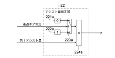
なお、アシスト量補正器22は、図8に示すように、車両のギア位置が後退ギアであるか否かを示す後退ギア判定を、車両の操舵状態として取得し、取得した後退ギア判定に応じて、第1アシスト量を補正するように構成されていてもよい。図8は、本発明の実施の形態2におけるアシスト量補正器22の構成の第1の別例を示すブロック図である。
As shown in FIG. 8, the assist amount corrector 22 obtains a reverse gear determination indicating whether the gear position of the vehicle is the reverse gear as the steering state of the vehicle, and responds to the acquired reverse gear determination. Thus, the first assist amount may be corrected. FIG. 8 is a block diagram showing a first alternative example of the configuration of the assist amount corrector 22 according to Embodiment 2 of the present invention.
図8に示すアシスト量補正器22は、出力部221a、出力部222a、切り替え部223aおよび乗算部224aを備える。
ア シ ス ト The assist amount corrector 22 shown in FIG. 8 includes an output unit 221a, an output unit 222a, a switching unit 223a, and a multiplication unit 224a.
出力部221aは、固定値である0を切り替え部223aに出力する。出力部222aは、固定値である1を切り替え部223aに出力する。
The output unit 221a outputs a fixed value of 0 to the switching unit 223a. The output unit 222a outputs a fixed value of 1 to the switching unit 223a.
切り替え部223aには、上述した後退ギア判定が入力される。切り替え部223aは、入力される後退ギア判定に基づいて、出力部221aの出力値および出力部222aの出力値のいずれかを選択し、選択した方の値を乗算部224aに出力する。
The above-described reverse gear determination is input to the switching unit 223a. The switching unit 223a selects one of the output value of the output unit 221a and the output value of the output unit 222a based on the input reverse gear determination, and outputs the selected value to the multiplication unit 224a.
切り替え部223aは、後退ギア判定において、車両のギア位置が後退ギアであることを示す場合には、出力部221aの出力値を切り替え部223aに出力する。一方、切り替え部223aは、後退ギア判定において、車両のギア位置が後退ギアであることを示さない場合には、出力部222aの出力値を切り替え部223aに出力する。
The switching unit 223a outputs the output value of the output unit 221a to the switching unit 223a when the reverse gear determination indicates that the gear position of the vehicle is the reverse gear. On the other hand, when the reverse gear determination does not indicate that the gear position of the vehicle is the reverse gear, the switching unit 223a outputs the output value of the output unit 222a to the switching unit 223a.
乗算部224aは、アシスト量演算器19から入力された第1アシスト量に、切り替え部223aの出力値を乗算することで得られる値をローパスフィルタ20に出力する。
The multiplication unit 224a outputs to the low-pass filter 20 a value obtained by multiplying the first assist amount input from the assist amount calculator 19 by the output value of the switching unit 223a.
このように、アシスト量補正器22は、車両のギア位置が後退ギアである場合、すなわち、車両が後退する場合には、第1アシスト量を0に補正する。これにより、車両が後退する場合、横断勾配に対応するアシストを停止することができる。
ア シ ス ト Thus, the assist amount corrector 22 corrects the first assist amount to 0 when the gear position of the vehicle is the reverse gear, that is, when the vehicle is moving backward. Thus, when the vehicle moves backward, the assist corresponding to the cross slope can be stopped.
なお、アシスト量補正器22は、図9に示すように、モータ回転角度センサ7によって検出されたモータ5の回転角度を微分することで得られる操舵速度を、車両の操舵状態として取得し、取得した操舵速度に応じて、第1アシスト量を補正するように構成されていてもよい。図9は、本発明の実施の形態2におけるアシスト量補正器22の構成の第2の別例を示すブロック図である。
The assist amount corrector 22 acquires a steering speed obtained by differentiating the rotation angle of the motor 5 detected by the motor rotation angle sensor 7 as a steering state of the vehicle, as shown in FIG. The first assist amount may be corrected in accordance with the steering speed thus set. FIG. 9 is a block diagram illustrating a second alternative example of the configuration of the assist amount corrector 22 according to Embodiment 2 of the present invention.
図9に示すアシスト量補正器22は、補正部221b、出力部222b、判定部223b、切り替え部224bおよび乗算部225bを備える。
The assist amount corrector 22 illustrated in FIG. 9 includes a correction unit 221b, an output unit 222b, a determination unit 223b, a switching unit 224b, and a multiplication unit 225b.
補正部221bは、操舵速度/補正ゲインマップに従って、入力された操舵速度の大きさに対応する補正ゲインを演算し、その補正ゲインを切り替え部224bに出力する。なお、操舵速度/補正ゲインマップは、操舵速度の大きさと、対応する補正ゲインとが関連付けられたマップであり、操舵速度の大きさが大きくなるにつれて補正ゲインが1から0に減少するように予め設定される。
The correction unit 221b calculates a correction gain corresponding to the input steering speed according to the steering speed / correction gain map, and outputs the correction gain to the switching unit 224b. The steering speed / correction gain map is a map in which the magnitude of the steering speed and the corresponding correction gain are associated with each other, and is set in advance so that the correction gain decreases from 1 to 0 as the magnitude of the steering speed increases. Is set.
補正部221bおよび判定部223bに入力される操舵速度は、操舵制御装置12によって演算される。この操舵速度は、上述したように、モータ回転角度センサ7によって検出されるモータ5の回転角度を微分することで得られる。
The steering speed input to the correction unit 221b and the determination unit 223b is calculated by the steering control device 12. This steering speed is obtained by differentiating the rotation angle of the motor 5 detected by the motor rotation angle sensor 7 as described above.
出力部222bは、固定値である1を切り替え部224に出力する。判定部223bは、入力された操舵速度の符号と、ローパスフィルタ20から入力された第2アシスト量の前回値の符号とを比較する。判定部223bは、その比較によって、操舵速度の符号と第2アシスト量の前回値の符号とが互いに正負逆であるか否かを判定する。判定部223bは、その判定結果を切り替え部224bに出力する。
(4) The output unit 222b outputs a fixed value of 1 to the switching unit 224. The determination unit 223b compares the sign of the input steering speed with the sign of the previous value of the second assist amount input from the low-pass filter 20. The determination unit 223b determines whether the sign of the steering speed and the sign of the previous value of the second assist amount are opposite to each other by the comparison. The determination unit 223b outputs the determination result to the switching unit 224b.
切り替え部224bは、判定部223bの出力値である判定結果に基づいて、補正部221bの出力値と出力部222bの出力値とのいずれかを選択し、選択した方の値を乗算部225bに出力する。
The switching unit 224b selects one of the output value of the correction unit 221b and the output value of the output unit 222b based on the determination result that is the output value of the determination unit 223b, and outputs the selected value to the multiplication unit 225b. Output.
切り替え部224bは、操舵速度の符号と、第2アシスト量の前回値の符号とが互いに正負逆であると判定された場合には、出力部222bの出力値を乗算部225bに出力する。一方、切り替え部224bは、操舵速度の符号と、第2アシスト量の前回値の符号とが互いに正負逆でない、すなわち、これらの符号が互いに同符号であると判定された場合には、補正部221bの出力値を乗算部225bに出力する。
The switching unit 224b outputs the output value of the output unit 222b to the multiplication unit 225b when it is determined that the sign of the steering speed and the sign of the previous value of the second assist amount are opposite to each other. On the other hand, when the sign of the steering speed and the sign of the previous value of the second assist amount are not opposite to each other, that is, when it is determined that these signs are the same sign, the switching unit 224b sets the correction unit. 221b is output to the multiplier 225b.
乗算部225bは、アシスト量演算器19から入力された第1アシスト量に、切り替え部224bの出力値を乗算することで得られる値をローパスフィルタ20に出力する。
The multiplication unit 225 b outputs a value obtained by multiplying the first assist amount input from the assist amount calculator 19 by the output value of the switching unit 224 b to the low-pass filter 20.
このように、アシスト量補正器22は、操舵速度の符号と、第2アシスト量の前回値の符号とが互いに正負逆である場合には、第1アシスト量を補正することなく、ローパスフィルタ20に出力する。
As described above, when the sign of the steering speed and the sign of the previous value of the second assist amount are opposite in sign to each other, the assist amount corrector 22 does not correct the first assist amount, and does not correct the first assist amount. Output to
操舵速度の符号と、第2アシスト量の前回値の符号とが互いに同符号である場合、車両が横断勾配路を登る方向に運転者が操舵していると考えられる。この場合、横断勾配に対応するアシストが不要である。
If the sign of the steering speed and the sign of the previous value of the second assist amount are the same, it is considered that the driver is steering in the direction in which the vehicle climbs the cross slope. In this case, the assist corresponding to the cross slope is unnecessary.
そこで、アシスト量補正器22は、操舵速度の符号と、第2アシスト量の前回値の符号とが互いに同符号である場合、操舵速度の大きさに応じて第1アシスト量が小さくなるように補正するように構成されている。このような構成によって、車両が横断勾配路を登る方向に運転者が操舵している状況での横断勾配に対応するアシスト量を低減させることができる。
Therefore, if the sign of the steering speed and the sign of the previous value of the second assist amount have the same sign, the assist amount corrector 22 reduces the first assist amount according to the magnitude of the steering speed. It is configured to correct. With such a configuration, it is possible to reduce the assist amount corresponding to the cross slope when the driver is steering in the direction in which the vehicle climbs the cross slope.
以上、本実施の形態2によれば、操舵制御装置は、先の実施の形態1の構成に対して、アシスト量演算器によって演算された第1アシスト量を、車両の操舵状態に応じて補正するアシスト量補正器をさらに備えて構成されている。これにより、先の実施の形態1と同様の効果が得られるとともに、さらに、車両の操舵状態によって必要に応じて横断勾配に対応するアシスト量を低減させることができる。
As described above, according to the second embodiment, the steering control device corrects the first assist amount calculated by the assist amount calculator according to the steering state of the vehicle with respect to the configuration of the first embodiment. It is further provided with an assist amount corrector that performs the operation. Thus, the same effect as that of the first embodiment can be obtained, and the assist amount corresponding to the transverse gradient can be reduced as necessary depending on the steering state of the vehicle.
実施の形態3.
本発明の実施の形態3では、先の実施の形態2の構成に対して、アシスト量補正器22の代わりに、カットオフ周波数調整器23を備えて構成されている操舵制御装置12について説明する。なお、実施の形態3では、先の実施の形態1および2と同様である点の説明を省略し、先の実施の形態1および2と異なる点を中心に説明する。Embodiment 3 FIG.
In the third embodiment of the present invention, a description will be given of asteering control device 12 configured to include a cutoff frequency adjuster 23 instead of the assist amount corrector 22 in the configuration of the second embodiment. . In the third embodiment, the description of the same points as those in the first and second embodiments will be omitted, and the description will be focused on points different from the first and second embodiments.
本発明の実施の形態3では、先の実施の形態2の構成に対して、アシスト量補正器22の代わりに、カットオフ周波数調整器23を備えて構成されている操舵制御装置12について説明する。なお、実施の形態3では、先の実施の形態1および2と同様である点の説明を省略し、先の実施の形態1および2と異なる点を中心に説明する。
In the third embodiment of the present invention, a description will be given of a
図10は、本発明の実施の形態3における操舵制御装置12の構成を示すブロック図である。図10において、操舵制御装置12は、インターフェース部13、横断勾配推定器18、処理器24、アシスト量演算器19、カットオフ周波数調整器23、ローパスフィルタ20、モータ制御器21およびモータ駆動器17を備える。
FIG. 10 is a block diagram showing a configuration of the steering control device 12 according to Embodiment 3 of the present invention. In FIG. 10, the steering control device 12 includes an interface unit 13, a transverse gradient estimator 18, a processor 24, an assist amount calculator 19, a cutoff frequency adjuster 23, a low-pass filter 20, a motor controller 21, and a motor driver 17. Is provided.
カットオフ周波数調整器23は、インターフェース部13を介して、操舵トルクセンサ4から操舵トルクを取得する。カットオフ周波数調整器23は、ローパスフィルタ20から第2アシスト量の前回値を取得する。
The cutoff frequency adjuster 23 acquires the steering torque from the steering torque sensor 4 via the interface unit 13. The cutoff frequency adjuster 23 acquires the previous value of the second assist amount from the low-pass filter 20.
カットオフ周波数調整器23は、取得した操舵トルクおよび第2アシスト量の前回値に基づいて、ローパスフィルタ20の第1カットオフ周波数fc_Aを調整し、調整後の第1カットオフ周波数fc_Aをローパスフィルタ20に与える。ローパスフィルタ20は、カットオフ周波数調整器23から与えられた調整後の第1カットオフ周波数fc_Aを用いて、アシスト量演算器19から入力された第1アシスト量に対して、先の実施の形態1で説明したローパスフィルタ処理を施すことで、第2アシスト量を演算する。
The cutoff frequency adjuster 23 adjusts the first cutoff frequency fc_A of the low-pass filter 20 based on the acquired steering torque and the previous value of the second assist amount, and adjusts the adjusted first cutoff frequency fc_A to the low-pass filter. Give to 20. The low-pass filter 20 uses the adjusted first cut-off frequency fc_A given from the cut-off frequency adjuster 23 to apply the first assist amount input from the assist amount calculator 19 to the first embodiment. The second assist amount is calculated by performing the low-pass filter processing described in 1 above.
カットオフ周波数調整器23の構成について、図11を参照しながら説明する。図11は、本発明の実施の形態3におけるカットオフ周波数調整器23の構成を示すブロック図である。
The configuration of the cutoff frequency adjuster 23 will be described with reference to FIG. FIG. 11 is a block diagram showing a configuration of cutoff frequency adjuster 23 according to Embodiment 3 of the present invention.
図11において、カットオフ周波数調整器23は、出力部231、出力部232、判定部233、切り替え部234および乗算部235を備える。
In FIG. 11, the cutoff frequency adjuster 23 includes an output unit 231, an output unit 232, a determination unit 233, a switching unit 234, and a multiplication unit 235.
出力部231は、固定値である0を切り替え部234に出力する。出力部232は、固定値である1を切り替え部234に出力する。
The output unit 231 outputs a fixed value of 0 to the switching unit 234. The output unit 232 outputs a fixed value of 1 to the switching unit 234.
判定部233は、操舵トルクセンサ4から入力された操舵トルクの符号と、ローパスフィルタ20から入力された第2アシスト量の前回値の符号とを比較する。判定部233は、その比較によって、操舵トルクの符号と第2アシスト量の前回値の符号とが互いに正負逆であるか否かを判定する。判定部233は、その判定結果を切り替え部234に出力する。
The determination unit 233 compares the sign of the steering torque input from the steering torque sensor 4 with the sign of the previous value of the second assist amount input from the low-pass filter 20. The determination unit 233 determines whether the sign of the steering torque and the sign of the previous value of the second assist amount are opposite to each other by the comparison. The determination unit 233 outputs the result of the determination to the switching unit 234.
切り替え部234は、判定部233の出力値である判定結果に基づいて、出力部231の出力値と出力部232の出力値とのいずれかを選択し、選択した方の値を乗算部235に出力する。
The switching unit 234 selects one of the output value of the output unit 231 and the output value of the output unit 232 based on the determination result that is the output value of the determination unit 233, and outputs the selected value to the multiplication unit 235. Output.
切り替え部234は、操舵トルクの符号と、第2アシスト量の前回値の符号とが互いに正負逆であると判定された場合には、出力部231の出力値を乗算部235に出力する。一方、切り替え部234は、操舵トルクの符号と、第2アシスト量の前回値の符号とが互いに正負逆でない、すなわち、これらの符号が互いに同符号であると判定された場合には、出力部232の出力値を乗算部235に出力する。
The switching unit 234 outputs the output value of the output unit 231 to the multiplication unit 235 when it is determined that the sign of the steering torque and the sign of the previous value of the second assist amount are opposite to each other. On the other hand, when the sign of the steering torque and the sign of the previous value of the second assist amount are not opposite to each other, that is, when it is determined that these signs are the same sign, the switching unit 234 outputs to the output unit. The output value of H.232 is output to the multiplication unit 235.
乗算部235は、ローパスフィルタ20の第1カットオフ周波数fc_Aに、切り替え部234の出力値を乗算することで得られる値をローパスフィルタ20に与える。
The multiplication unit 235 gives the low-pass filter 20 a value obtained by multiplying the first cutoff frequency fc_A of the low-pass filter 20 by the output value of the switching unit 234.
このように、カットオフ周波数調整器23は、操舵トルクの符号と、第2アシスト量の前回値の符号とが互いに正負逆である場合には、第1カットオフ周波数fc_Aを0に調整する。これにより、車両が横断勾配路を下る方向に運転者が操舵していると考えられる場合に第2アシスト量が増加することを抑制することができる。その結果、操舵トルクのアシストが運転者の操舵と干渉することを抑制することができる。
As described above, the cutoff frequency adjuster 23 adjusts the first cutoff frequency fc_A to 0 when the sign of the steering torque and the sign of the previous value of the second assist amount are opposite to each other. Thus, it is possible to suppress an increase in the second assist amount when it is considered that the driver is steering in a direction in which the vehicle goes down the cross slope. As a result, it is possible to suppress the assist of the steering torque from interfering with the driver's steering.
カットオフ周波数調整器23は、操舵トルクの符号と、第2アシスト量の前回値の符号とが互いに正負逆である場合、第2カットオフ周波数fc_Bを予め設定される設定値になるように大きく調整してもよい。これにより、アシスト量の減少を早めることができ、結果として、操舵トルクのアシストが運転者の操舵と干渉することを抑制することができる。
When the sign of the steering torque and the sign of the previous value of the second assist amount are opposite in sign to each other, the cutoff frequency adjuster 23 increases the second cutoff frequency fc_B so as to become a preset value. It may be adjusted. As a result, the decrease in the assist amount can be accelerated, and as a result, it is possible to suppress the assist of the steering torque from interfering with the driver's steering.
なお、カットオフ周波数調整器23は、図12に示すように、車両のギア位置が後退ギアであるか否かを示す後退ギア判定を、車両の操舵状態として取得し、取得した後退ギア判定に応じて、第1カットオフ周波数fc_Aを調整するように構成されていてもよい。図12は、本発明の実施の形態3におけるカットオフ周波数調整器23の構成の第1の別例を示すブロック図である。
As shown in FIG. 12, the cutoff frequency adjuster 23 obtains a reverse gear determination indicating whether the gear position of the vehicle is the reverse gear as the steering state of the vehicle, and performs the determination on the obtained reverse gear determination. The first cutoff frequency fc_A may be adjusted accordingly. FIG. 12 is a block diagram illustrating a first different example of the configuration of the cutoff frequency adjuster 23 according to Embodiment 3 of the present invention.
図12に示すカットオフ周波数調整器23は、出力部231a、出力部232a、切り替え部233aおよび乗算部234aを備える。
The cutoff frequency adjuster 23 shown in FIG. 12 includes an output unit 231a, an output unit 232a, a switching unit 233a, and a multiplication unit 234a.
出力部231aは、固定値である0を切り替え部233aに出力する。出力部232aは、固定値である1を切り替え部233aに出力する。
The output unit 231a outputs a fixed value of 0 to the switching unit 233a. The output unit 232a outputs a fixed value of 1 to the switching unit 233a.
切り替え部233aには、上述した後退ギア判定が入力される。切り替え部233aは、入力される後退ギア判定に基づいて、出力部231aの出力値および出力部232aの出力値のいずれかを選択し、選択した方の値を乗算部234aに出力する。
The reverse gear determination described above is input to the switching unit 233a. The switching unit 233a selects one of the output value of the output unit 231a and the output value of the output unit 232a based on the input reverse gear determination, and outputs the selected value to the multiplication unit 234a.
切り替え部233aは、後退ギア判定において、車両のギア位置が後退ギアであることを示す場合には、出力部231aの出力値を切り替え部233aに出力する。一方、切り替え部233aは、後退ギア判定において、車両のギア位置が後退ギアであることを示さない場合には、出力部232aの出力値を切り替え部233aに出力する。
The switching unit 233a outputs the output value of the output unit 231a to the switching unit 233a when the reverse gear determination indicates that the gear position of the vehicle is the reverse gear. On the other hand, when the reverse gear determination does not indicate that the gear position of the vehicle is the reverse gear, the switching unit 233a outputs the output value of the output unit 232a to the switching unit 233a.
乗算部234aは、ローパスフィルタ20の第1カットオフ周波数fc_Aに、切り替え部233aの出力値を乗算することで得られる値をローパスフィルタ20に出力する。
The multiplication unit 234a outputs to the low-pass filter 20 a value obtained by multiplying the first cutoff frequency fc_A of the low-pass filter 20 by the output value of the switching unit 233a.
このように、カットオフ周波数調整器23は、車両のギア位置が後退ギアである場合、すなわち、車両が後退する場合には、第1カットオフ周波数fc_Aを0に調整する。これにより、車両が後退する場合、第1カットオフ周波数fc_Aが0になるので、第2アシスト量の増加が停止する。
Thus, the cutoff frequency adjuster 23 adjusts the first cutoff frequency fc_A to 0 when the gear position of the vehicle is a reverse gear, that is, when the vehicle moves backward. Accordingly, when the vehicle moves backward, the first cutoff frequency fc_A becomes 0, and the increase in the second assist amount stops.
なお、カットオフ周波数調整器23は、図13に示すように、モータ回転角度センサ7によって検出されたモータ5の回転角度を微分することで得られる操舵速度を、車両の操舵状態として取得し、取得した操舵速度に応じて、第1カットオフ周波数fc_Aを調整するように構成されていてもよい。図13は、本発明の実施の形態3におけるカットオフ周波数調整器23の構成の第2の別例を示すブロック図である。
The cutoff frequency adjuster 23 acquires a steering speed obtained by differentiating the rotation angle of the motor 5 detected by the motor rotation angle sensor 7 as a steering state of the vehicle, as shown in FIG. The first cutoff frequency fc_A may be adjusted according to the acquired steering speed. FIG. 13 is a block diagram showing a second alternative example of the configuration of cutoff frequency adjuster 23 according to Embodiment 3 of the present invention.
図13に示すカットオフ周波数調整器23は、出力部231b、出力部232b、判定部233b、切り替え部234bおよび乗算部235bを備える。
The cutoff frequency adjuster 23 illustrated in FIG. 13 includes an output unit 231b, an output unit 232b, a determination unit 233b, a switching unit 234b, and a multiplication unit 235b.
判定部233bに入力される操舵速度は、操舵制御装置12によって演算される。この操舵速度は、モータ回転角度センサ7によって検出されるモータ5の回転角度を微分することで得られる。
The steering speed input to the determination unit 233b is calculated by the steering control device 12. This steering speed is obtained by differentiating the rotation angle of the motor 5 detected by the motor rotation angle sensor 7.
判定部233bは、入力された操舵速度の符号と、ローパスフィルタ20から入力された第2アシスト量の前回値の符号とを比較する。判定部233bは、その比較によって、操舵速度の符号と第2アシスト量の前回値の符号とが互いに正負逆であるか否かを判定する。判定部233bは、その判定結果を切り替え部234bに出力する。
The determination unit 233b compares the sign of the input steering speed with the sign of the previous value of the second assist amount input from the low-pass filter 20. Based on the comparison, the determination unit 233b determines whether the sign of the steering speed and the sign of the previous value of the second assist amount are opposite to each other. The determination unit 233b outputs the result of the determination to the switching unit 234b.
切り替え部234bは、判定部233bの出力値である判定結果に基づいて、出力部231bの出力値と出力部232bの出力値とのいずれかを選択し、選択した方の値を乗算部235bに出力する。
The switching unit 234b selects one of the output value of the output unit 231b and the output value of the output unit 232b based on the determination result that is the output value of the determination unit 233b, and outputs the selected value to the multiplication unit 235b. Output.
切り替え部234bは、操舵速度の符号と、第2アシスト量の前回値の符号とが互いに正負逆であると判定された場合には、出力部232bの出力値を乗算部235bに出力する。一方、切り替え部234bは、操舵速度の符号と、第2アシスト量の前回値の符号とが互いに正負逆でない、すなわち、これらの符号が互いに同符号であると判定された場合には、出力部231bの出力値を乗算部235bに出力する。
The switching unit 234b outputs the output value of the output unit 232b to the multiplication unit 235b when it is determined that the sign of the steering speed and the sign of the previous value of the second assist amount are opposite to each other. On the other hand, the switching unit 234b outputs the output unit when the sign of the steering speed and the sign of the previous value of the second assist amount are not opposite to each other, that is, when it is determined that these signs are the same sign. The output value of 231b is output to the multiplier 235b.
乗算部235bは、ローパスフィルタ20の第1カットオフ周波数fc_Aに、切り替え部234bの出力値を乗算することで得られる値をローパスフィルタ20に与える。
The multiplication unit 235b gives the low-pass filter 20 a value obtained by multiplying the first cutoff frequency fc_A of the low-pass filter 20 by the output value of the switching unit 234b.
このように、カットオフ周波数調整器23は、操舵速度の符号と、第2アシスト量の前回値の符号とが互いに同符号である場合には、第1カットオフ周波数fc_Aを0に調整する。これにより、車両が横断勾配路を登る方向に運転者が操舵していると考えられる場合、第1カットオフ周波数fc_Aが0になるので、第2アシスト量の増加が停止する。
As described above, the cutoff frequency adjuster 23 adjusts the first cutoff frequency fc_A to 0 when the sign of the steering speed and the sign of the previous value of the second assist amount are the same sign. Accordingly, when the driver is considered to be steering in the direction in which the vehicle climbs the cross slope, the first cutoff frequency fc_A becomes 0, and the increase in the second assist amount stops.
なお、カットオフ周波数調整器23は、演算される操舵速度および検出されるヨーレートに基づいて、車両が直進走行しているか否かを判定し、その判定結果に基づいて、ローパスフィルタ20の第1カットオフ周波数fc_Aを調整するように構成されていてもよい。なお、操舵速度閾値およびヨーレート閾値は、予め設定される値である。
The cutoff frequency adjuster 23 determines whether or not the vehicle is traveling straight, based on the calculated steering speed and the detected yaw rate, and based on the determination result, determines whether the first The cutoff frequency fc_A may be configured to be adjusted. Note that the steering speed threshold value and the yaw rate threshold value are preset values.
この場合、カットオフ周波数調整器23は、操舵速度が操舵速度閾値よりも小さく、かつ、ヨーレートがヨーレート閾値よりも小さい場合には、車両が直進走行していると判定し、そうでない場合には、車両が直進走行していないと判定する。
In this case, the cutoff frequency adjuster 23 determines that the vehicle is traveling straight when the steering speed is smaller than the steering speed threshold and the yaw rate is smaller than the yaw rate threshold, and otherwise, It is determined that the vehicle is not traveling straight.
カットオフ周波数調整器23は、車両が直進走行してないと判定した場合、第1カットオフ周波数fc_Aを0に調整する一方、車両が直進走行していると判定した場合には、第1カットオフ周波数fc_Aの調整を行わない。これにより、横断勾配路を車両が直進走行している場合には、アシスト量を増加させることができ、横断勾配路を車両が直進走行していない場合には、アシスト量の増加を停止させることができる。その結果、操舵トルクのアシストが運転者の操舵と干渉することを抑制することができる。
The cutoff frequency adjuster 23 adjusts the first cutoff frequency fc_A to 0 when it is determined that the vehicle is not traveling straight, and performs the first cutoff when it is determined that the vehicle is traveling straight. No adjustment of the off frequency fc_A is performed. As a result, the assist amount can be increased when the vehicle is traveling straight on the cross slope, and the increase in the assist amount is stopped when the vehicle is not traveling straight on the cross slope. Can be. As a result, it is possible to suppress the assist of the steering torque from interfering with the driver's steering.
以上、本実施の形態3によれば、操舵制御装置は、先の実施の形態2の構成に対して、アシスト量補正器の代わりに、ローパスフィルタの第1カットオフ周波数を、車両の操舵状態に応じて調整するカットオフ周波数調整器をさらに備えて構成されている。このように構成した場合であっても、先の実施の形態2と同様の効果が得られる。
As described above, according to the third embodiment, the steering control device is different from the configuration of the second embodiment in that the first cutoff frequency of the low-pass filter is used instead of the assist amount corrector. And a cutoff frequency adjuster that adjusts according to. Even in the case of such a configuration, the same effect as in the second embodiment can be obtained.
実施の形態4.
本発明の実施の形態4では、先の実施の形態1~3と異なる方法によってアシスト量演算器19が第1アシスト量を演算するように構成されている操舵制御装置12について説明する。なお、実施の形態4では、先の実施の形態1~3と同様である点の説明を省略し、先の実施の形態1~3と異なる点を中心に説明する。Embodiment 4 FIG.
In a fourth embodiment of the present invention, a description will be given of asteering control device 12 in which the assist amount calculator 19 is configured to calculate the first assist amount by a method different from the first to third embodiments. In the fourth embodiment, the description of the same points as in the first to third embodiments will be omitted, and the description will be focused on the points different from the first to third embodiments.
本発明の実施の形態4では、先の実施の形態1~3と異なる方法によってアシスト量演算器19が第1アシスト量を演算するように構成されている操舵制御装置12について説明する。なお、実施の形態4では、先の実施の形態1~3と同様である点の説明を省略し、先の実施の形態1~3と異なる点を中心に説明する。
In a fourth embodiment of the present invention, a description will be given of a
図14は、本発明の実施の形態4における操舵制御装置12の構成を示すブロック図である。図14において、操舵制御装置12は、インターフェース部13、横断勾配推定器18、アシスト量演算器19、ローパスフィルタ20、モータ制御器21およびモータ駆動器17を備える。
FIG. 14 is a block diagram showing a configuration of the steering control device 12 according to Embodiment 4 of the present invention. In FIG. 14, the steering control device 12 includes an interface unit 13, a transverse gradient estimator 18, an assist amount calculator 19, a low-pass filter 20, a motor controller 21, and a motor driver 17.
横断勾配推定器18は、インターフェース部13を介して、車速センサ8から車速を取得し、自車位置推定器25から自車位置を取得する。自車位置推定器25は、自車が走行している位置である自車位置を、公知の方法によって推定し、その自車位置を出力する。
The crossing gradient estimator 18 acquires the vehicle speed from the vehicle speed sensor 8 via the interface unit 13 and acquires the vehicle position from the vehicle position estimator 25. The host vehicle position estimator 25 estimates the host vehicle position where the host vehicle is traveling by a known method, and outputs the host vehicle position.
横断勾配推定器18は、走行路情報を記憶している。走行路情報は、自車位置と、自車位置に対応する横断勾配および路面曲率とが関連付けられたデータであり、予め設定される。なお、横断勾配推定器18は、ナビゲーションシステムを用いて構成されていてもよい。
The crossing gradient estimator 18 stores traveling road information. The travel path information is data in which the own vehicle position is associated with the transverse slope and the road surface curvature corresponding to the own vehicle position, and is set in advance. Note that the cross slope estimator 18 may be configured using a navigation system.
横断勾配推定器18は、自車位置推定器25から取得した自車位置に対応する横断勾配および路面曲率を、走行路情報から決定し、決定した横断勾配および路面曲率をアシスト量演算器19に出力する。横断勾配推定器18は、車速センサ8から取得した車速をアシスト量演算器19に出力する。
The crossing slope estimator 18 determines the crossing slope and the road surface curvature corresponding to the own vehicle position acquired from the own vehicle position estimator 25 from the traveling road information, and sends the determined crossing slope and the road surface curvature to the assist amount calculator 19. Output. The crossing gradient estimator 18 outputs the vehicle speed acquired from the vehicle speed sensor 8 to the assist amount calculator 19.
なお、横断勾配推定器18は、車両に設けられた加速度センサおよび角速度センサのそれぞれの検出値を用いて、公知の手法によって、横断勾配および路面曲率を推定するように構成されていてもよい。
Note that the crossing gradient estimator 18 may be configured to estimate the crossing gradient and the road surface curvature by a known method using the respective detection values of the acceleration sensor and the angular velocity sensor provided in the vehicle.
アシスト量演算器19は、横断勾配推定器18から入力された横断勾配、路面曲率および車速に基づいて、第1アシスト量を演算し、演算した第1アシスト量をローパスフィルタ20に出力する。ローパスフィルタ20は、アシスト量演算器19から入力された第1アシスト量に対して、先の実施の形態1で説明したローパスフィルタ処理を施すことで、第2アシスト量を演算する。
The assist amount calculator 19 calculates the first assist amount based on the cross slope, the road surface curvature, and the vehicle speed input from the cross slope estimator 18, and outputs the calculated first assist amount to the low-pass filter 20. The low-pass filter 20 calculates the second assist amount by performing the low-pass filter processing described in the first embodiment on the first assist amount input from the assist amount calculator 19.
ここで、アシスト量演算器19が第1アシスト量を演算する方法の例について、図15を参照しながら説明する。図15は、本発明の実施の形態4における車両に作用する横断勾配による外乱および遠心力による外乱を模式的に示す図である。
Here, an example of a method in which the assist amount calculator 19 calculates the first assist amount will be described with reference to FIG. FIG. 15 is a diagram schematically showing a disturbance due to a transverse gradient and a disturbance due to centrifugal force acting on a vehicle according to Embodiment 4 of the present invention.
アシスト量演算器19は、横断勾配推定器18から入力された横断勾配θ、路面曲率ρおよび車速Vを用いて、以下の式(6)に従って、車両の横方向に作用する外乱Fy_distを求める。
The assist amount calculator 19 obtains a disturbance Fy_dist acting in the lateral direction of the vehicle using the transverse gradient θ, the road surface curvature ρ, and the vehicle speed V input from the transverse gradient estimator 18 according to the following equation (6).
Fy_dist=mgsinθ-mρV2cosθ (6)
Fy_dist = mgsinθ−mρV 2 cosθ (6)
アシスト量演算器19は、上述の外乱Fy_distをキャンセルするように、先の実施の形態1と同様の方法で、補償トルクTcomp1を求める。この補償トルクTcomp1が第1アシスト量に相当する。
The assist amount calculator 19 calculates the compensation torque Tcomp1 in the same manner as in the first embodiment so as to cancel the disturbance Fy_dist described above. This compensation torque Tcomp1 corresponds to the first assist amount.
このように、アシスト量演算器19は、横断勾配推定器18から入力された横断勾配、路面曲率および車速に基づいて第1アシスト量を演算するように構成されている。このような構成によって、車速が低く、横断勾配による外乱と遠心力による外乱が釣り合わない結果として、車両が偏向する場合であっても、その偏向を抑えるように運転者の操舵をアシストすることが可能となる。
As described above, the assist amount calculator 19 is configured to calculate the first assist amount based on the cross slope, the road surface curvature, and the vehicle speed input from the cross slope estimator 18. With such a configuration, even when the vehicle is deflected as a result of the vehicle speed being low and the disturbance due to the cross gradient and the disturbance due to the centrifugal force being unbalanced, it is possible to assist the driver in steering so as to suppress the deflection. It becomes possible.
以上、本実施の形態4によれば、先の実施の形態1~3とは異なり、横断勾配推定器は、自車位置推定器によって推定された自車位置に対応する横断勾配および路面曲率を、走行路情報から推定するように構成されている。また、アシスト量演算器は、車速センサによって検出された車速と、横断勾配推定器によって推定された横断勾配および路面曲率とに基づいて、第1アシスト量を演算するように構成されている。これにより、先の実施の形態1~3と同様の効果が得られるとともに、車両が偏向する場合にも対応して運転者の操舵をアシストすることが可能となる
As described above, according to the fourth embodiment, unlike the first to third embodiments, the crossing gradient estimator calculates the crossing gradient and the road surface curvature corresponding to the own vehicle position estimated by the own vehicle position estimator. , And is estimated from the travel path information. Further, the assist amount calculator is configured to calculate the first assist amount based on the vehicle speed detected by the vehicle speed sensor, the crossing gradient and the road surface curvature estimated by the crossing gradient estimator. Thus, the same effects as those of the first to third embodiments can be obtained, and the steering of the driver can be assisted even when the vehicle is deflected.
なお、本発明の実施例として実施の形態1~4を説明したが、本発明は実施の形態1~4の各構成に限定されるものではなく、本発明の趣旨を逸脱しない範囲において、実施の形態1~4の各構成を適宜組み合わせたり、各構成に一部変形を加えたり、各構成を一部省略したりすることが可能である。
The first to fourth embodiments have been described as examples of the present invention. However, the present invention is not limited to each of the configurations of the first to fourth embodiments, and may be implemented without departing from the spirit of the present invention. It is possible to appropriately combine the configurations of the first to fourth embodiments, partially modify each configuration, or partially omit each configuration.
1 ハンドル、2 ステアリング軸、3 転舵輪、4 操舵トルクセンサ、5 モータ、6 減速機構、7 モータ回転角度センサ、8 車速センサ、9 ヨーレートセンサ、10 横加速度センサ、11 電流センサ、12 操舵制御装置、13 インターフェース部、14 CPU、15 ROM、16 RAM、17 モータ駆動器、18 横断勾配推定器、19 アシスト量演算器、20 ローパスフィルタ、201 減算部、202 ゲイン部、203 ゲイン部、204 判定部、205 切り替え部、206 加算部、207 遅延部、21 モータ制御器、22 アシスト量補正器、221 補正部、222 出力部、223 判定部、224 切り替え部、225 乗算部、221a 出力部、222a 出力部、223a 切り替え部、224a 乗算部、221b 補正部、222b 出力部、223b 判定部、224b 切り替え部、225b 乗算部、23 カットオフ周波数調整器、231 出力部、232 出力部、233 判定部、234 切り替え部、235 乗算部、231a 出力部、232a 出力部、233a 切り替え部、234a 乗算部、231b 出力部、232b 出力部、233b 判定部、234b 切り替え部、235b 乗算部、24 処理器、25 自車位置推定器。
1 steering wheel, 2 steering wheel, 3 steering wheel, 4 steering torque sensor, 5 motor, 6 deceleration mechanism, 7 motor rotation angle sensor, 8 vehicle speed sensor, 9 yaw rate sensor, 10 lateral acceleration sensor, 11 current sensor, 12 steering control device , 13 interface unit, 14 CPU, 15 ROM, 16 RAM, 17 motor driver, 18 cross gradient estimator, 19 assist amount calculator, 20 low pass filter, 201 subtraction unit, 202 gain unit, 203 gain unit, 204 judgment unit Switching unit, 205 switching unit, 206 addition unit, 207 delay unit, 21 motor controller, 22 assist amount correction unit, 221 correction unit, 222 output unit, 223 determination unit, 224 switching unit, 225 multiplication unit, 221a output unit, 222a output Part, 22 a switching section, 224a multiplier section, 221b correction section, 222b output section, 223b determination section, 224b switching section, 225b multiplier section, 23 cutoff frequency adjuster, 231 output section, 232 output section, 233 determination section, 234 switching section , 235} multiplication unit, 231a output unit, 232a output unit, 233a switching unit, 234a multiplication unit, 231b output unit, 232b output unit, 233b determination unit, 234b switching unit, 235b multiplication unit, 24 processing unit, 25 vehicle position estimation vessel.
Claims (13)
- 車両が走行する路面の横断勾配を推定する横断勾配推定器と、
前記横断勾配推定器によって推定された前記横断勾配に基づいて第1アシスト量を演算するアシスト量演算器と、
前記アシスト量演算器によって演算された前記第1アシスト量に対して、ローパスフィルタ処理を施し、前記ローパスフィルタ処理後の前記第1アシスト量を、第2アシスト量として出力するローパスフィルタと、
前記ローパスフィルタによって出力される前記第2アシスト量を用いて、操舵アシストトルクを発生させるモータを制御するモータ制御器と、
を備え、
前記ローパスフィルタは、
前記第2アシスト量が増加変化する場合と、前記第2アシスト量が減少変化する場合とに応じて、前記ローパスフィルタのカットオフ周波数を、第1カットオフ周波数と、前記第1カットオフ周波数よりも高い値に設定される第2カットオフ周波数との間で切り替える
操舵制御装置。 A cross slope estimator for estimating the cross slope of the road surface on which the vehicle travels;
An assist amount calculator that calculates a first assist amount based on the cross gradient estimated by the cross gradient estimator;
A low-pass filter that performs a low-pass filter process on the first assist amount calculated by the assist amount calculator, and outputs the first assist amount after the low-pass filter process as a second assist amount;
A motor controller that controls a motor that generates a steering assist torque by using the second assist amount output by the low-pass filter;
With
The low-pass filter,
According to the case where the second assist amount increases and the case where the second assist amount decreases and changes, the cutoff frequency of the low-pass filter is changed from the first cutoff frequency to the first cutoff frequency. The steering control device switches between a second cut-off frequency that is also set to a high value. - 前記ローパスフィルタは、
前記第2アシスト量が増加変化する場合には、前記カットオフ周波数を前記第1カットオフ周波数にし、前記第2アシスト量が減少変化する場合には、前記カットオフ周波数を前記第2カットオフ周波数にする
請求項1に記載の操舵制御装置。 The low-pass filter,
When the second assist amount increases and changes, the cutoff frequency is set to the first cutoff frequency. When the second assist amount decreases and changes, the cutoff frequency is set to the second cutoff frequency. The steering control device according to claim 1. - 前記アシスト量演算器によって演算された前記第1アシスト量を、前記車両の操舵状態に応じて補正するアシスト量補正器をさらに備えた
請求項1または2に記載の操舵制御装置。 The steering control device according to claim 1, further comprising an assist amount corrector that corrects the first assist amount calculated by the assist amount calculator according to a steering state of the vehicle. - 前記アシスト量補正器は、前記車両のハンドルを介してステアリング軸に作用する操舵トルクを検出する操舵トルクセンサによって検出された前記操舵トルクを、前記操舵状態として取得し、取得した前記操舵トルクに応じて、前記第1アシスト量を補正する
請求項3に記載の操舵制御装置。 The assist amount corrector acquires the steering torque detected by a steering torque sensor that detects a steering torque acting on a steering shaft via a steering wheel of the vehicle as the steering state, and according to the acquired steering torque. The steering control device according to claim 3, wherein the first assist amount is corrected. - 前記アシスト量補正器は、前記モータの回転角度を検出するモータ回転角度センサによって検出された前記回転角度を微分することで得られる操舵速度を、前記操舵状態として取得し、取得した前記操舵速度に応じて、前記第1アシスト量を補正する
請求項3に記載の操舵制御装置。 The assist amount corrector acquires a steering speed obtained by differentiating the rotation angle detected by a motor rotation angle sensor that detects a rotation angle of the motor, as the steering state, and obtains the steering speed. The steering control device according to claim 3, wherein the first assist amount is corrected accordingly. - 前記アシスト量補正器は、前記車両のギア位置が後退ギアであるか否かを示す後退ギア判定を、前記操舵状態として取得し、取得した前記後退ギア判定に応じて、前記第1アシスト量を補正する
請求項3に記載の操舵制御装置。 The assist amount corrector acquires a reverse gear determination indicating whether or not the gear position of the vehicle is a reverse gear as the steering state, and determines the first assist amount according to the acquired reverse gear determination. The steering control device according to claim 3, wherein the correction is performed. - 前記ローパスフィルタの前記第1カットオフ周波数を、前記車両の操舵状態に応じて調整するカットオフ周波数調整器をさらに備えた
請求項1または2に記載の操舵制御装置。 The steering control device according to claim 1, further comprising a cutoff frequency adjuster that adjusts the first cutoff frequency of the low-pass filter according to a steering state of the vehicle. - 前記カットオフ周波数調整器は、前記車両のハンドルを介してステアリング軸に作用する操舵トルクを検出する操舵トルクセンサによって検出された前記操舵トルクを、前記操舵状態として取得し、取得した前記操舵トルクに応じて、前記第1カットオフ周波数を調整する
請求項7に記載の操舵制御装置。 The cutoff frequency adjuster obtains the steering torque detected by a steering torque sensor that detects a steering torque acting on a steering shaft via a steering wheel of the vehicle as the steering state. The steering control device according to claim 7, wherein the first cutoff frequency is adjusted accordingly. - 前記カットオフ周波数調整器は、前記モータの回転角度を検出するモータ回転角度センサによって検出された前記回転角度を微分することで得られる操舵速度を、前記操舵状態として取得し、取得した前記操舵速度に応じて、前記第1カットオフ周波数を調整する
請求項7に記載の操舵制御装置。 The cutoff frequency adjuster acquires a steering speed obtained by differentiating the rotation angle detected by a motor rotation angle sensor that detects a rotation angle of the motor as the steering state, and acquires the acquired steering speed. The steering control device according to claim 7, wherein the first cutoff frequency is adjusted in accordance with the following. - 前記カットオフ周波数調整器は、前記車両のギア位置が後退ギアであるか否かを示す後退ギア判定を、前記操舵状態として取得し、取得した前記後退ギア判定に応じて、前記第1カットオフ周波数を調整する
請求項7に記載の操舵制御装置。 The cutoff frequency adjuster acquires a reverse gear determination indicating whether or not the gear position of the vehicle is a reverse gear as the steering state, and, in accordance with the acquired reverse gear determination, obtains the first cutoff. The steering control device according to claim 7, wherein the frequency is adjusted. - 前記横断勾配推定器によって推定された前記横断勾配に対して、レートリミッタ処理および不感帯処理の少なくとも一方の処理を施す処理器をさらに備えた
請求項1から10のいずれか1項に記載の操舵制御装置。 The steering control according to any one of claims 1 to 10, further comprising a processor that performs at least one of a rate limiter process and a dead zone process on the cross slope estimated by the cross slope estimator. apparatus. - 前記横断勾配推定器は、前記車両の車速を検出する車速センサによって検出された前記車速と、前記車両のヨーレートを検出するヨーレートセンサによって検出された前記ヨーレートと、前記車両の横加速度を検出する横加速度センサによって検出された前記横加速度とに基づいて、前記横断勾配を推定する
請求項1から11のいずれか1項に記載の操舵制御装置。 The crossing gradient estimator includes a vehicle speed detected by a vehicle speed sensor that detects a vehicle speed of the vehicle, the yaw rate detected by a yaw rate sensor that detects a yaw rate of the vehicle, and a lateral speed that detects a lateral acceleration of the vehicle. The steering control device according to any one of claims 1 to 11, wherein the traverse gradient is estimated based on the lateral acceleration detected by an acceleration sensor. - 前記横断勾配推定器は、前記車両の自車位置と、前記自車位置に対応する横断勾配および路面曲率とが関連付けられた走行路情報を記憶し、前記自車位置推定器によって推定された前記自車位置に対応する前記横断勾配および前記路面曲率を、前記走行路情報から推定し、
前記アシスト量演算器は、前記車両の車速を検出する車速センサによって検出された前記車速と、前記横断勾配推定器によって推定された前記横断勾配および前記路面曲率とに基づいて、前記第1アシスト量を演算する
請求項1から11のいずれか1項に記載の操舵制御装置。 The crossing gradient estimator stores travel road information in which the own vehicle position of the vehicle is associated with a crossing gradient and a road surface curvature corresponding to the own vehicle position, and the crossing gradient estimator estimated by the own vehicle position estimator is used. Estimating the cross slope and the road surface curvature corresponding to the vehicle position from the travel path information,
The assist amount calculator calculates the first assist amount based on the vehicle speed detected by a vehicle speed sensor that detects a vehicle speed of the vehicle and the crossing gradient and the road surface curvature estimated by the crossing gradient estimator. The steering control device according to any one of claims 1 to 11.
Priority Applications (5)
| Application Number | Priority Date | Filing Date | Title |
|---|---|---|---|
| CN201880095968.3A CN112512900B (en) | 2018-07-31 | 2018-07-31 | Steering control device |
| JP2020533938A JP6925535B2 (en) | 2018-07-31 | 2018-07-31 | Steering control device |
| PCT/JP2018/028665 WO2020026342A1 (en) | 2018-07-31 | 2018-07-31 | Steering control system |
| US17/253,693 US11891136B2 (en) | 2018-07-31 | 2018-07-31 | Steering control device |
| EP18928456.5A EP3831694B1 (en) | 2018-07-31 | 2018-07-31 | Steering control system |
Applications Claiming Priority (1)
| Application Number | Priority Date | Filing Date | Title |
|---|---|---|---|
| PCT/JP2018/028665 WO2020026342A1 (en) | 2018-07-31 | 2018-07-31 | Steering control system |
Publications (1)
| Publication Number | Publication Date |
|---|---|
| WO2020026342A1 true WO2020026342A1 (en) | 2020-02-06 |
Family
ID=69232219
Family Applications (1)
| Application Number | Title | Priority Date | Filing Date |
|---|---|---|---|
| PCT/JP2018/028665 WO2020026342A1 (en) | 2018-07-31 | 2018-07-31 | Steering control system |
Country Status (5)
| Country | Link |
|---|---|
| US (1) | US11891136B2 (en) |
| EP (1) | EP3831694B1 (en) |
| JP (1) | JP6925535B2 (en) |
| CN (1) | CN112512900B (en) |
| WO (1) | WO2020026342A1 (en) |
Cited By (1)
| Publication number | Priority date | Publication date | Assignee | Title |
|---|---|---|---|---|
| JP7323487B2 (en) | 2020-04-06 | 2023-08-08 | 日野自動車株式会社 | vehicle controller |
Families Citing this family (3)
| Publication number | Priority date | Publication date | Assignee | Title |
|---|---|---|---|---|
| DE102019206980B4 (en) * | 2019-05-14 | 2023-06-22 | Volkswagen Aktiengesellschaft | Method and steering control device for determining a manipulated variable for setting a power steering torque in a vehicle steering system |
| KR20210135738A (en) * | 2020-05-06 | 2021-11-16 | 현대모비스 주식회사 | Apparatus and method for controlling motor driven power steering system of vehicle |
| CN114435371B (en) * | 2022-03-25 | 2024-03-01 | 北京主线科技有限公司 | Road gradient estimation method and device |
Citations (8)
| Publication number | Priority date | Publication date | Assignee | Title |
|---|---|---|---|---|
| JP2000142433A (en) * | 1998-05-19 | 2000-05-23 | Denso Corp | Power steering method and device |
| JP2005219681A (en) | 2004-02-06 | 2005-08-18 | Mitsubishi Motors Corp | Vehicular power steering device, and vehicular disturbance estimating device |
| JP2006044505A (en) * | 2004-08-05 | 2006-02-16 | Honda Motor Co Ltd | Power steering device |
| JP2007112366A (en) * | 2005-10-24 | 2007-05-10 | Nissan Motor Co Ltd | Power steering device |
| JP2007153249A (en) * | 2005-12-08 | 2007-06-21 | Toyota Motor Corp | Steering device of vehicle |
| JP2012101791A (en) * | 2011-12-29 | 2012-05-31 | Denso Corp | Road surface gradient estimation device, device and system for controlling vehicle |
| WO2014054476A1 (en) * | 2012-10-04 | 2014-04-10 | 日産自動車株式会社 | Steering control device |
| JP2018114934A (en) * | 2017-01-20 | 2018-07-26 | 株式会社ジェイテクト | Control device for vehicle |
Family Cites Families (15)
| Publication number | Priority date | Publication date | Assignee | Title |
|---|---|---|---|---|
| JP3060863B2 (en) * | 1994-12-14 | 2000-07-10 | トヨタ自動車株式会社 | Vehicle behavior estimation device |
| JP2008062816A (en) * | 2006-09-08 | 2008-03-21 | Nsk Ltd | Control device of electric power steering device |
| JP5238441B2 (en) | 2008-10-03 | 2013-07-17 | 本田技研工業株式会社 | Electric power steering device |
| JP5444819B2 (en) | 2009-04-27 | 2014-03-19 | 株式会社ジェイテクト | Electric power steering device |
| JP5499526B2 (en) * | 2009-06-19 | 2014-05-21 | 株式会社ジェイテクト | Electric power steering device |
| CN102030034B (en) * | 2010-09-17 | 2013-05-08 | 杭州正强电子技术有限公司 | Electric power steering assistance control method |
| JP2012131471A (en) | 2010-11-29 | 2012-07-12 | Honda Motor Co Ltd | Electric steering system |
| CN104011514B (en) * | 2011-12-27 | 2015-12-09 | 丰田自动车株式会社 | The loading condition presuming method of vehicle and device |
| JP5751178B2 (en) * | 2012-01-20 | 2015-07-22 | トヨタ自動車株式会社 | Electric power steering device |
| CN103786783B (en) * | 2012-10-29 | 2018-10-26 | 福特全球技术公司 | Power steering system with ball-screw |
| JP6160860B2 (en) * | 2013-06-11 | 2017-07-12 | 株式会社ジェイテクト | Electric power steering device |
| DE112015001321T5 (en) * | 2014-03-19 | 2016-12-15 | Hitachi Automotive Systems, Ltd. | Electric power steering apparatus and control apparatus for an electric power steering apparatus |
| WO2016080198A1 (en) * | 2014-11-19 | 2016-05-26 | 日本精工株式会社 | Electric power steering device |
| FR3037671B1 (en) * | 2015-06-19 | 2017-06-16 | Jtekt Europe Sas | USING A PHASE ADVANCE FILTER TO SEPARATE THE SPRING ADJUSTMENT FROM THE STEERING WHEEL ADJUSTING THE STABILITY OF AN ASSISTED STEERING CONTROL |
| JP7070376B2 (en) * | 2018-11-30 | 2022-05-18 | トヨタ自動車株式会社 | Disturbance detector for vehicles |
-
2018
- 2018-07-31 CN CN201880095968.3A patent/CN112512900B/en active Active
- 2018-07-31 EP EP18928456.5A patent/EP3831694B1/en active Active
- 2018-07-31 JP JP2020533938A patent/JP6925535B2/en active Active
- 2018-07-31 US US17/253,693 patent/US11891136B2/en active Active
- 2018-07-31 WO PCT/JP2018/028665 patent/WO2020026342A1/en unknown
Patent Citations (8)
| Publication number | Priority date | Publication date | Assignee | Title |
|---|---|---|---|---|
| JP2000142433A (en) * | 1998-05-19 | 2000-05-23 | Denso Corp | Power steering method and device |
| JP2005219681A (en) | 2004-02-06 | 2005-08-18 | Mitsubishi Motors Corp | Vehicular power steering device, and vehicular disturbance estimating device |
| JP2006044505A (en) * | 2004-08-05 | 2006-02-16 | Honda Motor Co Ltd | Power steering device |
| JP2007112366A (en) * | 2005-10-24 | 2007-05-10 | Nissan Motor Co Ltd | Power steering device |
| JP2007153249A (en) * | 2005-12-08 | 2007-06-21 | Toyota Motor Corp | Steering device of vehicle |
| JP2012101791A (en) * | 2011-12-29 | 2012-05-31 | Denso Corp | Road surface gradient estimation device, device and system for controlling vehicle |
| WO2014054476A1 (en) * | 2012-10-04 | 2014-04-10 | 日産自動車株式会社 | Steering control device |
| JP2018114934A (en) * | 2017-01-20 | 2018-07-26 | 株式会社ジェイテクト | Control device for vehicle |
Non-Patent Citations (1)
| Title |
|---|
| See also references of EP3831694A4 |
Cited By (1)
| Publication number | Priority date | Publication date | Assignee | Title |
|---|---|---|---|---|
| JP7323487B2 (en) | 2020-04-06 | 2023-08-08 | 日野自動車株式会社 | vehicle controller |
Also Published As
| Publication number | Publication date |
|---|---|
| US11891136B2 (en) | 2024-02-06 |
| CN112512900A (en) | 2021-03-16 |
| EP3831694A1 (en) | 2021-06-09 |
| JP6925535B2 (en) | 2021-08-25 |
| US20210261190A1 (en) | 2021-08-26 |
| CN112512900B (en) | 2022-09-20 |
| EP3831694B1 (en) | 2022-06-08 |
| EP3831694A4 (en) | 2021-08-04 |
| JPWO2020026342A1 (en) | 2020-12-17 |
Similar Documents
| Publication | Publication Date | Title |
|---|---|---|
| WO2020026342A1 (en) | Steering control system | |
| JP6078124B1 (en) | Vehicle control apparatus and vehicle control method | |
| US8594892B2 (en) | Electric power steering apparatus for vehicle | |
| US7957867B2 (en) | Steering system of vehicle | |
| JP5093552B2 (en) | Vehicle steering system | |
| US20120303218A1 (en) | Electric steering device | |
| JP2005335504A (en) | Vehicular stabilizer device | |
| JP6263527B2 (en) | Centering method of steering wheel for power assist steering of automobile | |
| JP5085510B2 (en) | Electric power steering device | |
| JP4751874B2 (en) | Vehicle rear wheel rudder angle control device and rear wheel rudder angle control method | |
| WO2020021817A1 (en) | Steering control device for vehicle | |
| EP3150463B1 (en) | Steering control device | |
| JP5185792B2 (en) | Yaw rate controller | |
| KR20170114660A (en) | Understeer/oversteer compensating control method of vehicle | |
| JP2012180011A (en) | Attitude control device of vehicle | |
| JP5068638B2 (en) | Vehicle rear wheel toe angle control device and rear wheel toe angle control method | |
| JP2005239010A (en) | Power steering device for vehicle | |
| JP6815572B1 (en) | Control device for electric power steering device and electric power steering device | |
| JP2005280368A (en) | Power steering device for vehicle and disturbance presumption device for vehicle | |
| JP5081728B2 (en) | Electric power steering device for vehicles | |
| KR101886083B1 (en) | Total control system for vehicle and method thereof | |
| JPH08133116A (en) | Right and left force estimation device and steering controller using it | |
| JPH11245838A (en) | Rear wheel steering controller for vehicle | |
| JP2018095071A (en) | Electric power steering device | |
| JP2011063114A (en) | Rear wheel steering device |
Legal Events
| Date | Code | Title | Description |
|---|---|---|---|
| 121 | Ep: the epo has been informed by wipo that ep was designated in this application |
Ref document number: 18928456 Country of ref document: EP Kind code of ref document: A1 |
|
| ENP | Entry into the national phase |
Ref document number: 2020533938 Country of ref document: JP Kind code of ref document: A |
|
| NENP | Non-entry into the national phase |
Ref country code: DE |
|
| ENP | Entry into the national phase |
Ref document number: 2018928456 Country of ref document: EP Effective date: 20210301 |