WO2014054368A1 - 電源装置および電池モジュール切り替え方法 - Google Patents
電源装置および電池モジュール切り替え方法 Download PDFInfo
- Publication number
- WO2014054368A1 WO2014054368A1 PCT/JP2013/073657 JP2013073657W WO2014054368A1 WO 2014054368 A1 WO2014054368 A1 WO 2014054368A1 JP 2013073657 W JP2013073657 W JP 2013073657W WO 2014054368 A1 WO2014054368 A1 WO 2014054368A1
- Authority
- WO
- WIPO (PCT)
- Prior art keywords
- battery module
- battery
- voltage
- load
- voltage value
- Prior art date
Links
Images


Classifications
-
- H—ELECTRICITY
- H01—ELECTRIC ELEMENTS
- H01M—PROCESSES OR MEANS, e.g. BATTERIES, FOR THE DIRECT CONVERSION OF CHEMICAL ENERGY INTO ELECTRICAL ENERGY
- H01M10/00—Secondary cells; Manufacture thereof
- H01M10/42—Methods or arrangements for servicing or maintenance of secondary cells or secondary half-cells
- H01M10/44—Methods for charging or discharging
- H01M10/441—Methods for charging or discharging for several batteries or cells simultaneously or sequentially
-
- B—PERFORMING OPERATIONS; TRANSPORTING
- B60—VEHICLES IN GENERAL
- B60L—PROPULSION OF ELECTRICALLY-PROPELLED VEHICLES; SUPPLYING ELECTRIC POWER FOR AUXILIARY EQUIPMENT OF ELECTRICALLY-PROPELLED VEHICLES; ELECTRODYNAMIC BRAKE SYSTEMS FOR VEHICLES IN GENERAL; MAGNETIC SUSPENSION OR LEVITATION FOR VEHICLES; MONITORING OPERATING VARIABLES OF ELECTRICALLY-PROPELLED VEHICLES; ELECTRIC SAFETY DEVICES FOR ELECTRICALLY-PROPELLED VEHICLES
- B60L1/00—Supplying electric power to auxiliary equipment of vehicles
- B60L1/003—Supplying electric power to auxiliary equipment of vehicles to auxiliary motors, e.g. for pumps, compressors
-
- B—PERFORMING OPERATIONS; TRANSPORTING
- B60—VEHICLES IN GENERAL
- B60L—PROPULSION OF ELECTRICALLY-PROPELLED VEHICLES; SUPPLYING ELECTRIC POWER FOR AUXILIARY EQUIPMENT OF ELECTRICALLY-PROPELLED VEHICLES; ELECTRODYNAMIC BRAKE SYSTEMS FOR VEHICLES IN GENERAL; MAGNETIC SUSPENSION OR LEVITATION FOR VEHICLES; MONITORING OPERATING VARIABLES OF ELECTRICALLY-PROPELLED VEHICLES; ELECTRIC SAFETY DEVICES FOR ELECTRICALLY-PROPELLED VEHICLES
- B60L3/00—Electric devices on electrically-propelled vehicles for safety purposes; Monitoring operating variables, e.g. speed, deceleration or energy consumption
- B60L3/12—Recording operating variables ; Monitoring of operating variables
-
- B—PERFORMING OPERATIONS; TRANSPORTING
- B60—VEHICLES IN GENERAL
- B60L—PROPULSION OF ELECTRICALLY-PROPELLED VEHICLES; SUPPLYING ELECTRIC POWER FOR AUXILIARY EQUIPMENT OF ELECTRICALLY-PROPELLED VEHICLES; ELECTRODYNAMIC BRAKE SYSTEMS FOR VEHICLES IN GENERAL; MAGNETIC SUSPENSION OR LEVITATION FOR VEHICLES; MONITORING OPERATING VARIABLES OF ELECTRICALLY-PROPELLED VEHICLES; ELECTRIC SAFETY DEVICES FOR ELECTRICALLY-PROPELLED VEHICLES
- B60L50/00—Electric propulsion with power supplied within the vehicle
- B60L50/50—Electric propulsion with power supplied within the vehicle using propulsion power supplied by batteries or fuel cells
- B60L50/51—Electric propulsion with power supplied within the vehicle using propulsion power supplied by batteries or fuel cells characterised by AC-motors
-
- B—PERFORMING OPERATIONS; TRANSPORTING
- B60—VEHICLES IN GENERAL
- B60L—PROPULSION OF ELECTRICALLY-PROPELLED VEHICLES; SUPPLYING ELECTRIC POWER FOR AUXILIARY EQUIPMENT OF ELECTRICALLY-PROPELLED VEHICLES; ELECTRODYNAMIC BRAKE SYSTEMS FOR VEHICLES IN GENERAL; MAGNETIC SUSPENSION OR LEVITATION FOR VEHICLES; MONITORING OPERATING VARIABLES OF ELECTRICALLY-PROPELLED VEHICLES; ELECTRIC SAFETY DEVICES FOR ELECTRICALLY-PROPELLED VEHICLES
- B60L58/00—Methods or circuit arrangements for monitoring or controlling batteries or fuel cells, specially adapted for electric vehicles
- B60L58/10—Methods or circuit arrangements for monitoring or controlling batteries or fuel cells, specially adapted for electric vehicles for monitoring or controlling batteries
- B60L58/12—Methods or circuit arrangements for monitoring or controlling batteries or fuel cells, specially adapted for electric vehicles for monitoring or controlling batteries responding to state of charge [SoC]
- B60L58/15—Preventing overcharging
-
- B—PERFORMING OPERATIONS; TRANSPORTING
- B60—VEHICLES IN GENERAL
- B60L—PROPULSION OF ELECTRICALLY-PROPELLED VEHICLES; SUPPLYING ELECTRIC POWER FOR AUXILIARY EQUIPMENT OF ELECTRICALLY-PROPELLED VEHICLES; ELECTRODYNAMIC BRAKE SYSTEMS FOR VEHICLES IN GENERAL; MAGNETIC SUSPENSION OR LEVITATION FOR VEHICLES; MONITORING OPERATING VARIABLES OF ELECTRICALLY-PROPELLED VEHICLES; ELECTRIC SAFETY DEVICES FOR ELECTRICALLY-PROPELLED VEHICLES
- B60L58/00—Methods or circuit arrangements for monitoring or controlling batteries or fuel cells, specially adapted for electric vehicles
- B60L58/10—Methods or circuit arrangements for monitoring or controlling batteries or fuel cells, specially adapted for electric vehicles for monitoring or controlling batteries
- B60L58/18—Methods or circuit arrangements for monitoring or controlling batteries or fuel cells, specially adapted for electric vehicles for monitoring or controlling batteries of two or more battery modules
- B60L58/22—Balancing the charge of battery modules
-
- H—ELECTRICITY
- H01—ELECTRIC ELEMENTS
- H01M—PROCESSES OR MEANS, e.g. BATTERIES, FOR THE DIRECT CONVERSION OF CHEMICAL ENERGY INTO ELECTRICAL ENERGY
- H01M10/00—Secondary cells; Manufacture thereof
- H01M10/42—Methods or arrangements for servicing or maintenance of secondary cells or secondary half-cells
- H01M10/48—Accumulators combined with arrangements for measuring, testing or indicating the condition of cells, e.g. the level or density of the electrolyte
- H01M10/482—Accumulators combined with arrangements for measuring, testing or indicating the condition of cells, e.g. the level or density of the electrolyte for several batteries or cells simultaneously or sequentially
-
- H—ELECTRICITY
- H02—GENERATION; CONVERSION OR DISTRIBUTION OF ELECTRIC POWER
- H02J—CIRCUIT ARRANGEMENTS OR SYSTEMS FOR SUPPLYING OR DISTRIBUTING ELECTRIC POWER; SYSTEMS FOR STORING ELECTRIC ENERGY
- H02J7/00—Circuit arrangements for charging or depolarising batteries or for supplying loads from batteries
- H02J7/0013—Circuit arrangements for charging or depolarising batteries or for supplying loads from batteries acting upon several batteries simultaneously or sequentially
- H02J7/0014—Circuits for equalisation of charge between batteries
- H02J7/0016—Circuits for equalisation of charge between batteries using shunting, discharge or bypass circuits
-
- H—ELECTRICITY
- H02—GENERATION; CONVERSION OR DISTRIBUTION OF ELECTRIC POWER
- H02J—CIRCUIT ARRANGEMENTS OR SYSTEMS FOR SUPPLYING OR DISTRIBUTING ELECTRIC POWER; SYSTEMS FOR STORING ELECTRIC ENERGY
- H02J7/00—Circuit arrangements for charging or depolarising batteries or for supplying loads from batteries
- H02J7/0013—Circuit arrangements for charging or depolarising batteries or for supplying loads from batteries acting upon several batteries simultaneously or sequentially
- H02J7/0025—Sequential battery discharge in systems with a plurality of batteries
-
- H—ELECTRICITY
- H02—GENERATION; CONVERSION OR DISTRIBUTION OF ELECTRIC POWER
- H02J—CIRCUIT ARRANGEMENTS OR SYSTEMS FOR SUPPLYING OR DISTRIBUTING ELECTRIC POWER; SYSTEMS FOR STORING ELECTRIC ENERGY
- H02J7/00—Circuit arrangements for charging or depolarising batteries or for supplying loads from batteries
- H02J7/0063—Circuit arrangements for charging or depolarising batteries or for supplying loads from batteries with circuits adapted for supplying loads from the battery
-
- H—ELECTRICITY
- H02—GENERATION; CONVERSION OR DISTRIBUTION OF ELECTRIC POWER
- H02J—CIRCUIT ARRANGEMENTS OR SYSTEMS FOR SUPPLYING OR DISTRIBUTING ELECTRIC POWER; SYSTEMS FOR STORING ELECTRIC ENERGY
- H02J7/00—Circuit arrangements for charging or depolarising batteries or for supplying loads from batteries
- H02J7/007—Regulation of charging or discharging current or voltage
- H02J7/00712—Regulation of charging or discharging current or voltage the cycle being controlled or terminated in response to electric parameters
- H02J7/007182—Regulation of charging or discharging current or voltage the cycle being controlled or terminated in response to electric parameters in response to battery voltage
-
- B—PERFORMING OPERATIONS; TRANSPORTING
- B60—VEHICLES IN GENERAL
- B60L—PROPULSION OF ELECTRICALLY-PROPELLED VEHICLES; SUPPLYING ELECTRIC POWER FOR AUXILIARY EQUIPMENT OF ELECTRICALLY-PROPELLED VEHICLES; ELECTRODYNAMIC BRAKE SYSTEMS FOR VEHICLES IN GENERAL; MAGNETIC SUSPENSION OR LEVITATION FOR VEHICLES; MONITORING OPERATING VARIABLES OF ELECTRICALLY-PROPELLED VEHICLES; ELECTRIC SAFETY DEVICES FOR ELECTRICALLY-PROPELLED VEHICLES
- B60L2240/00—Control parameters of input or output; Target parameters
- B60L2240/40—Drive Train control parameters
- B60L2240/54—Drive Train control parameters related to batteries
- B60L2240/545—Temperature
-
- B—PERFORMING OPERATIONS; TRANSPORTING
- B60—VEHICLES IN GENERAL
- B60L—PROPULSION OF ELECTRICALLY-PROPELLED VEHICLES; SUPPLYING ELECTRIC POWER FOR AUXILIARY EQUIPMENT OF ELECTRICALLY-PROPELLED VEHICLES; ELECTRODYNAMIC BRAKE SYSTEMS FOR VEHICLES IN GENERAL; MAGNETIC SUSPENSION OR LEVITATION FOR VEHICLES; MONITORING OPERATING VARIABLES OF ELECTRICALLY-PROPELLED VEHICLES; ELECTRIC SAFETY DEVICES FOR ELECTRICALLY-PROPELLED VEHICLES
- B60L2240/00—Control parameters of input or output; Target parameters
- B60L2240/40—Drive Train control parameters
- B60L2240/54—Drive Train control parameters related to batteries
- B60L2240/547—Voltage
-
- B—PERFORMING OPERATIONS; TRANSPORTING
- B60—VEHICLES IN GENERAL
- B60L—PROPULSION OF ELECTRICALLY-PROPELLED VEHICLES; SUPPLYING ELECTRIC POWER FOR AUXILIARY EQUIPMENT OF ELECTRICALLY-PROPELLED VEHICLES; ELECTRODYNAMIC BRAKE SYSTEMS FOR VEHICLES IN GENERAL; MAGNETIC SUSPENSION OR LEVITATION FOR VEHICLES; MONITORING OPERATING VARIABLES OF ELECTRICALLY-PROPELLED VEHICLES; ELECTRIC SAFETY DEVICES FOR ELECTRICALLY-PROPELLED VEHICLES
- B60L2240/00—Control parameters of input or output; Target parameters
- B60L2240/40—Drive Train control parameters
- B60L2240/54—Drive Train control parameters related to batteries
- B60L2240/549—Current
-
- H—ELECTRICITY
- H02—GENERATION; CONVERSION OR DISTRIBUTION OF ELECTRIC POWER
- H02J—CIRCUIT ARRANGEMENTS OR SYSTEMS FOR SUPPLYING OR DISTRIBUTING ELECTRIC POWER; SYSTEMS FOR STORING ELECTRIC ENERGY
- H02J2310/00—The network for supplying or distributing electric power characterised by its spatial reach or by the load
- H02J2310/40—The network being an on-board power network, i.e. within a vehicle
- H02J2310/48—The network being an on-board power network, i.e. within a vehicle for electric vehicles [EV] or hybrid vehicles [HEV]
-
- Y—GENERAL TAGGING OF NEW TECHNOLOGICAL DEVELOPMENTS; GENERAL TAGGING OF CROSS-SECTIONAL TECHNOLOGIES SPANNING OVER SEVERAL SECTIONS OF THE IPC; TECHNICAL SUBJECTS COVERED BY FORMER USPC CROSS-REFERENCE ART COLLECTIONS [XRACs] AND DIGESTS
- Y02—TECHNOLOGIES OR APPLICATIONS FOR MITIGATION OR ADAPTATION AGAINST CLIMATE CHANGE
- Y02E—REDUCTION OF GREENHOUSE GAS [GHG] EMISSIONS, RELATED TO ENERGY GENERATION, TRANSMISSION OR DISTRIBUTION
- Y02E60/00—Enabling technologies; Technologies with a potential or indirect contribution to GHG emissions mitigation
- Y02E60/10—Energy storage using batteries
-
- Y—GENERAL TAGGING OF NEW TECHNOLOGICAL DEVELOPMENTS; GENERAL TAGGING OF CROSS-SECTIONAL TECHNOLOGIES SPANNING OVER SEVERAL SECTIONS OF THE IPC; TECHNICAL SUBJECTS COVERED BY FORMER USPC CROSS-REFERENCE ART COLLECTIONS [XRACs] AND DIGESTS
- Y02—TECHNOLOGIES OR APPLICATIONS FOR MITIGATION OR ADAPTATION AGAINST CLIMATE CHANGE
- Y02T—CLIMATE CHANGE MITIGATION TECHNOLOGIES RELATED TO TRANSPORTATION
- Y02T10/00—Road transport of goods or passengers
- Y02T10/60—Other road transportation technologies with climate change mitigation effect
- Y02T10/70—Energy storage systems for electromobility, e.g. batteries
Definitions
- the present invention relates to a power supply device that performs charging / discharging and a battery module switching method.
- a vehicle such as a forklift supplies power from all battery modules to an auxiliary machine such as a machine-side ECU (Electronic Control Unit) or lighting even when a key switch is off.
- auxiliary machine such as a machine-side ECU (Electronic Control Unit) or lighting even when a key switch is off.
- all the battery modules are in a state in which an electric current is supplied to the auxiliary machine while the vehicle is running or parked.
- a current always flows through the batteries included in the battery module. Therefore, the battery module and battery information cannot be obtained with high accuracy.
- a power supply device for an electric vehicle capable of extending a travel distance is known.
- a plurality of battery packs are prepared, the remaining capacity of these battery packs is detected, and each battery pack is sequentially selected one by one for driving the traveling motor based on the detection result.
- each battery pack a plurality of batteries are connected in series so that no circulating current is generated. As a result, the battery capacity can be increased while eliminating the battery deterioration caused by the circulating current. See, for example, US Pat.
- a parallel connection power storage system that prevents occurrence of incompatibility such as overcurrent and abnormal heat generation due to a large cross current at the time of parallel input.
- one or a plurality of chargeable / dischargeable storage elements are connected in series to form a storage element array, and the plurality of storage element arrays are connected in parallel.
- a switch for connecting to and disconnecting from the system for each storage element array; voltage monitoring means for detecting a voltage difference between the plurality of storage element arrays; and a storage element having a voltage difference detected by the voltage monitoring means within a predetermined value Control means for turning on only the switch for the storage element array when one or a plurality of arrays exist. See, for example, US Pat.
- the present invention has been made in view of the above situation, and a power supply device and battery module switching that accurately acquire information for knowing the state of the battery module and the battery while supplying power to a part of the load. It aims to provide a method.
- the power supply device which is one of the embodiments includes a plurality of battery modules in which a plurality of batteries are connected in series, a voltage measuring unit, a plurality of first switches, a specifying unit, a first switching unit, a second switching unit, It has a switching part and an acquisition part.
- the plurality of first switches are connected in series to each of the battery modules connected in parallel.
- the identification unit identifies the battery module.
- the first switching unit sets the first switch corresponding to the specified battery module to the connected state and corresponds to a battery module other than the specified battery module. All the first switches are turned off.
- the second switching unit places the first switch corresponding to the second battery module, which is a battery module that does not supply power to a part of the load, in the connected state. Moreover, the 1st switch corresponding to a 1st battery module is made into a cutoff state.
- the acquisition unit acquires the open circuit voltage of each battery of the second battery module that does not supply power to a part of the load.
- FIG. 6 is a flowchart illustrating an example of the operation according to the first exemplary embodiment.
- FIG. 6 is a flowchart illustrating an example of the operation according to the first exemplary embodiment.
- 6 is a diagram illustrating an example of a control unit according to Embodiment 2.
- FIG. 6 is a flowchart illustrating an example of a control unit according to Embodiment 2.
- the information for knowing the state of the battery module and the battery is, for example, information such as an open circuit voltage value (OCV) and a state of charge (SOC) of the battery module and the battery. .
- OCV open circuit voltage value
- SOC state of charge
- a battery voltage equalization process cell balance process
- (4) When switching battery modules, by specifying and switching the battery module on the switching side where the voltage difference between the battery modules to be switched is smaller than the determined threshold, the reflux current flowing between the battery modules becomes excessive. You can avoid it.
- Embodiment 1 will be described.
- FIG. 1 is a diagram showing an embodiment of a power supply device.
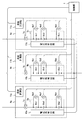
- FIG. 2 is a diagram illustrating an embodiment of the battery block and the control unit.
- the control unit 1 (computer) may be, for example, a central processing unit (CPU), a multi-core CPU, a programmable device (Field programmable gate array (FPGA), programmable logic device (PLD), etc.).
- the control unit 1 may include a storage unit, or may be connected to a storage unit provided separately from the control unit 1. It is assumed that the control unit 1 includes functions such as a travel control ECU.
- the load 2 and the auxiliary machine 3 are loads mounted on a vehicle, for example.
- a load 2 indicates an inverter, a drive motor, or the like.
- it is a load to which electric power is supplied for the forklift to travel.
- the auxiliary machine 3 is a part of a load such as a machine base side ECU and lighting, and is a load that supplies electric power even when the forklift is parked.
- the key switch 4 is a switch used when the vehicle is driven, and is, for example, an ignition switch.
- the main switch SW1 (second switch) is a switch that collectively connects the battery blocks 6a, 6b, and 6c that supply power to the load (load 2, auxiliary machine 3) side.
- the main switch SW1 is controlled to be connected (ON) and disconnected (OFF) by the control unit 1.
- a relay may be used as the main switch SW1.
- the main switch SW1 may not be provided.
- the control switch 5 has switches SW2a, SW2b, and SW2c (first switch).
- the first switches SW2a, SW2b, SW2c are connected in series to the battery blocks 6a, 6b, 6c connected in parallel.
- the first switches SW2a, SW2b, and SW2c are controlled to be connected (on) and cut off (off) by the control unit 1, and for example, a relay may be used.
- the battery block 6a includes a current measuring unit 7a, voltage measuring units 8a1, 8a2 to 8an, a battery module 9a, a voltage equalizing circuit 10a, and a temperature measuring unit 11a.
- the batteries Ba1 and Ba2 to Ban are connected in series to the battery module 9a.
- the battery block 6b includes a current measuring unit 7b, voltage measuring units 8b1, 8b2 to 8bn, a battery module 9b, a voltage equalizing circuit 10b, and a temperature measuring unit 11b. Batteries Bb1, Bb2 to Bbn are connected in series to the battery module 9b.
- the battery block 6c includes a current measuring unit 7c, voltage measuring units 8c1, 8c2 to 8cn, a battery module 9c, a voltage equalizing circuit 10c, and a temperature measuring unit 11c. Batteries Bc1, Bc2 to Bcn are connected in series to the battery module 9c.
- Current measuring units 7a, 7b, 7c measure currents flowing from the battery modules 9a, 9b, 9c to the load side.
- the current measuring units 7a, 7b, and 7c are, for example, ammeters. Each measured current value is sent to the control unit 1.
- Voltage measuring units 8a1, 8a2 to 8an, 8b1, 8b2 to 8bn, 8c1, 8c2 to 8cn measure the voltages of the batteries Ba1, Ba2 to Ban, Bb1, Bb2 to Bbn, Bc1, and Bc2 to Bcn. For example, a voltmeter. Each measured voltage value is sent to the control unit 1.
- a plurality of batteries Ba1, Ba2 to Ban are connected in series to the battery module 9a.
- a plurality of batteries Bb1, Bb2 to Bbn are connected in series to the battery module 9b.
- a plurality of batteries Bc1, Bc2 to Bcn are connected in series to the battery module 9c.
- the batteries Ba1, Ba2 to Ban, the batteries Bb1, Bb2 to Bbn, and the batteries Bc1, Bc2 to Bcn may be secondary batteries.
- the secondary battery for example, a lithium ion secondary battery, a nickel hydride secondary battery, or the like can be considered.
- the voltage equalization circuits 10a, 10b, and 10c are, for example, a passive cell balance circuit, an active cell balance circuit including a transformer coupling method and a converter method, and a progressive cell balance that performs cell balance by supplying power from the outside.
- a circuit etc. can be considered.
- details of the voltage equalization circuit are not shown in this example, in the case of a passive cell balance circuit, the voltage value of the other battery is aligned with the battery of the lowest voltage value among the plurality of batteries included in the battery module. Circuit. That is, the power of another battery is consumed using a resistance element or the like, and the voltage value is made uniform to the battery having the lowest voltage value.
- the voltage value of all the batteries of the battery module is equalized by moving the energy of the batteries in the battery module.
- the voltage value is made uniform by moving energy using a transformer.
- the voltage is made uniform by moving energy using a coil.
- the temperature measuring units 11a, 11b, and 11c measure the temperatures of the battery modules 9a, 9b, and 9c, or the temperatures of the batteries Ba1, Ba2 to Ban, Bb1, Bb2 to Bbn, Bc1, and Bc2 to Bcn, respectively, or a predetermined temperature.
- the measured temperature value is transmitted to the control unit 1.
- the control unit will be described.
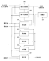
- FIG. 3 is a diagram showing an embodiment of the control unit.
- the control unit 1 includes a specifying unit 301, a first switching unit 302, a second switching unit 303, an acquisition unit 304, an estimation unit 305, an equalization unit 306, a correction unit 307, a storage unit 308, and the like.
- the storage unit 308 is provided in the control unit 1, but may be provided separately from the control unit 1.
- the specifying unit 301 is connected to the battery modules 9a, 9b, and 9c.
- Each voltage value is obtained.
- the voltage value of the battery module 9a may be the total value of the voltage values measured by the voltage measuring units 8a1, 8a2 to 8an.
- a voltage measuring unit that measures the voltage between the positive terminal of the battery Ba1 and the negative terminal of the battery Ban is provided, and the measured voltage value is used as the voltage value of the battery module 9a. Also good. You may obtain
- the first switching unit 302 supplies power only to the auxiliary machine 3 that is a part of the load
- the first switching unit 302 sets the main switch SW1 and the first switch corresponding to the specified battery module to a connected state. And all the 1st switches corresponding to battery modules other than the specified battery module are made into the interruption
- the key switch 4 of the vehicle is off and the vehicle is parked.
- the battery module specified in FIG. 2 is the battery module 9a
- the main switch SW1 and the first switch SW2a are connected, and the first switches SW2b and SW2c corresponding to the battery modules 9b and 9c are disconnected.
- the second switching unit 303 supplies the voltage value of the battery module that supplies power to the auxiliary machine 3 (the first battery module that supplies power to a part of the load) and the power to the auxiliary machine 3.
- the voltage difference between the maximum voltage value of the battery modules that are not used (second battery module that does not supply power to a part of the load) and the threshold value are compared.
- the first switch corresponding to the second battery module having the maximum voltage value is set to the connected state, and the first switch corresponding to the first battery module is set to the cutoff state.
- the threshold value is a value determined by multiplying the allowable current value of the battery, the internal resistance value of the battery, and the number of batteries included in the first battery module and the second battery module.
- the allowable current value of the battery is 200 [A]
- the internal resistance value of the battery is 1 “m ⁇ ”
- the number of batteries included in the first battery module and the second battery module is 10 (the battery included in one battery module). Is 5)
- the wiring resistance of the system through which the current flows and the resistance of the connection part connecting the wiring and the battery should be taken into consideration.
- the first switch SW2b corresponding to the battery module 9b is first connected. Thereafter, the first switch SW2a corresponding to the battery module 9a is turned off.
- the reflux current flowing between the battery modules to be switched can be prevented from becoming excessive.
- the acquisition unit 304 acquires the open circuit voltage value OCV of each battery of the second battery module.
- the first switch SW2a is in the connected state and the first switches SW2b and SW2c are in the cut-off state
- the voltages of the batteries Bb1, Bb2 to Bbn, Bc1, and Bc2 to Bcn included in the battery modules 9b and 9c are measured. Obtained from the units 8b1, 8b2 to 8bn, 8c1, and 8c2 to 8cn to obtain an open circuit voltage value OCV.
- the acquired open circuit voltage value OCV is stored in the storage unit 308.
- the battery module and the open circuit voltage value OCV of the battery which is one of information for knowing the state of the battery module and the battery, can be acquired.
- the estimation unit 305 estimates the state of charge (SOC: charge rate) using the open circuit voltage value OCV of each battery of the second battery module acquired by the acquisition unit 304. For example, the SOC corresponding to the acquired open circuit voltage value OCV is selected by referring to the estimation information 402 shown in FIG. 4 using the open circuit voltage value OCV acquired from the battery module 9b.
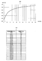
- FIG. 4 is a diagram showing an example of a table showing the relationship between OCV and SOC and estimation information. In the table 401 of FIG. 4, the vertical axis indicates OCV, and the horizontal axis indicates SOC.
- the estimation information 402 includes information stored in “open circuit voltage OCV” and “charge rate SOC”.
- the “open circuit voltage OCV” stores information used when the SOC is estimated using the open circuit voltage value OCV measured by the voltage measurement unit.
- “OCV1”, “OCV2”, “OCV3” to “OCV21”, etc. are stored as voltage ranges.
- Charge rate SOC stores information indicating SOC corresponding to information indicating the voltage range stored in “open circuit voltage OCV”.
- “100” indicating a charging rate of 100%, “95” indicating a charging rate of 95%, and the like are stored as the SOC.
- the battery module and the SOC of the battery which is one of information for knowing the battery module and the state of the battery, can be obtained with high accuracy. That is, since the open circuit voltage value OCV of each battery of the battery module in the open circuit is used, the current value and the voltage value of the circuit (closed circuit) in a state where current flows from the battery module to the auxiliary machine 3 are used to determine the SOC. It is possible to improve the SOC estimation accuracy than estimating.
- the equalization unit 306 controls the voltage equalization circuits 10a, 10b, and 10c that equalize the voltages of the batteries included in the second battery module for each second battery module. For example, when the first switches SW2b and SW2c are in the cut-off state, a control signal for executing cell balance is output to the voltage equalization circuits 10b and 10c corresponding to the battery modules 9b and 9c. As a result, as shown in the above (2), by creating a state in which no current flows through the battery module, cell balance can be executed for the battery module that is in an open circuit.
- the correction unit 307 When the correction unit 307 supplies power to the auxiliary machine 3 (a part of the load), the correction unit 307 performs offset correction of the current measurement unit corresponding to the open-circuit battery module. That is, since no current flows from the battery module in the open circuit to the auxiliary machine 3, the offset correction at the current value 0 [A] is possible as shown in the above (3). As a result, the measurement accuracy of the current measuring units 7a, 7b, 7c can be improved. For example, if the temperature value sent from the temperature measurement units 11b and 11c of the battery modules 9b and 9c that are currently in an open circuit is a determined temperature, the temperature measurement unit 11b corresponding to the battery modules 9b and 9c. , 11c to send an offset value to perform offset correction.
- FIG. 7 is a diagram illustrating an example of a data structure of state information according to the first embodiment.
- Information obtained in steps S501 to S512, which will be described later, is stored in the status information 701 shown in FIG.
- the status information 701 includes “battery module” “battery” “voltage value (CCV)” “module voltage value (CCV)” “module current value” “voltage value (OCV)” “module voltage value (OCV)” “SOC”.
- the information stored in the “switch” is stored.
- the “battery module” information for identifying the battery module is stored. In this example, “1”, “2”, and “3” are stored as identification information.
- the battery information for identifying the battery is stored.
- “Bcn” is stored in association with information for identifying the battery module.
- the “voltage value (CCV)” stores a voltage value CCV when power is supplied to the auxiliary machine 3.
- the information “Va1” “Va2” “Va3”... “Van” “Vb1” “Vb2” “Vb3”... “Vbn” “ “Vc1”, “Vc2”, “Vc3”...
- the “module voltage value (CCV)” stores the voltage value of the battery module when power is supplied to the auxiliary machine 3.
- information “Vact”, “Vbct”, and “Vcct” indicating the battery module voltage value CCV is stored in association with the information for identifying the battery module.
- the “module current value” stores the current value of the battery module when power is supplied to the auxiliary machine 3.
- information “Iat”, “Ibt”, and “Ict” indicating battery module current values are stored in association with information for identifying battery modules.
- the “voltage value (OCV)” stores the voltage value of the battery of the battery module that is not supplying power to the load 2 and the auxiliary machine 3 during parking (when the key switch 4 is off).
- information “Vbo1”, “Vbo2”, “Vbo3”... “Vbon” “Vco1” “Vco2” “Vco3”... “Vcon” indicating the open circuit voltage value OCV associated with the information for identifying the battery. Is stored.
- the open circuit voltage value OCV is not acquired.
- the “module voltage value (OCV)” stores the voltage value of the battery module that is not supplying power to the load 2 and the auxiliary machine 3.
- information “Vbot” and “Vcot” indicating the battery module voltage value are stored in association with information for identifying the battery module.
- the SOC estimated by the estimation unit 305 is stored in association with information for identifying the battery.
- information “SOCb1,” “SOCb2,” “SOCb3,” “SOCbn,” “SOCc1,” “SOCc2,” “SOCc3,” “SOCcn”, which indicates the SOC is stored in association with the information for identifying the battery. ing.
- the SOC of the battery module with the identification information “1” is not obtained.
- the “switch” stores a switch to be connected when the battery module supplies power to the auxiliary machine 3 during parking.
- the battery module identification information “1” is “SW1, Sw2a”
- the identification information “2” is “SW1, Sw2b”
- the identification information is “3”.
- SW1, Sw2c” is stored for the battery module.
- step S501 the control unit 1 determines whether or not the key switch 4 is off. If it is off (Yes), the process proceeds to step S502. If it is on (No), the process proceeds to step S511. When the key switch 4 is off, power to the load 2 is not supplied.
- step S502 the control unit 1 waits only for the time when the polarization of the batteries Ba1, Ba2 to Ban, Bb1, Bb2 to Bbn, Bc1, and Bc2 to Bcn of the battery modules 9a, 9b, and 9c is eliminated, and the process proceeds to step S503.
- the time for which the polarization is eliminated is a predetermined time, and may be determined, for example, by an experiment or by simulation. However, it is not necessary to completely eliminate the polarization.
- step S503 the control unit 1 sets the voltage values of the batteries Ba1, Ba2 to Ban, Bb1, Bb2 to Bbn, Bc1, and Bc2 to Bcn from the voltage measuring units 8a1, 8a2 to 8an, 8b1, 8b2 to 8bn, 8c1, 8c2 to 8cn. To get. And the voltage value of each battery module 9a, 9b, 9c is calculated
- step S504 the specifying unit 301 of the control unit 1 specifies the battery module having the maximum voltage value among the battery modules 9a, 9b, and 9c.
- the identified battery module is defined as a battery module m1 (first battery module), and the voltage value of the battery module m1 is defined as Vs1.
- the specifying unit 301 determines the voltage value of the battery module m1 that is currently supplying power to the auxiliary machine 3, and the voltage of other battery modules.
- the battery module having the largest voltage value is identified by comparing the value with the value. For example, in the case of the battery module 9a being fed, the battery module having the maximum voltage value is specified from the closed circuit voltage value CCV of the battery module 9a and the open circuit voltage value OCV of the other battery modules 9b and 9c. .
- step S505 the first switching unit 302 of the control unit 1 turns on the first switch corresponding to the identified battery module m1, and shuts off the first switches other than the identified battery module m1 ( Turn off.
- the first switch is the first switch SW2a corresponding to the battery module 9a.
- the first switches corresponding to the battery modules 9b and 9c other than the battery module 9a are the switches SW2b and SW2c. Even in this switching, it is desirable to consider that excessive current does not flow through the auxiliary machine 3 and the battery modules 9a, 9b, and 9c.
- step S506 the control unit 1 executes a first process described later on battery modules other than the battery module m1.
- the first process for example, the process shown in FIG. 6 can be considered.
- step S507 the second switching unit 303 of the control unit 1 identifies the battery module m2 having the maximum voltage among the battery modules (second battery modules) other than the battery module m1.
- the voltage value of the battery module m2 is set to Vs2. That is, in step S507, the battery module to be switched is specified.
- step S508 the second switching unit 303 determines whether or not the voltage difference between the voltage value Vs2 of the battery module m2 and the voltage value Vs1 of the battery module m1 is smaller than the threshold, and if smaller than the threshold (Vs2 ⁇ Vs1). ⁇ Threshold value: Yes), the process proceeds to step S509. If it is equal to or greater than the threshold value (No), it waits until it becomes smaller than the threshold value in step S508.
- the threshold value is a value obtained by multiplying the allowable current value of the battery, the internal resistance value of the battery, and the number of batteries included in the battery module m1 and the battery module m2.
- step S509 the second switching unit 303 sets the first switch corresponding to the battery module m2 to a connected state (ON).
- the first switch SW2b is brought into a connected state.
- step S510 the second switching unit 303 turns off the first switch corresponding to the battery module m1.
- the first switch SW2a is turned off (off).
- step S511 since the key switch is on, the control unit 1 turns on all the main switch and the first switch. That is, the switches SW1, SW2a, 2b, and 2c are all connected to supply power to the load 2 and the auxiliary machine 3 from all the battery modules 9a, 9b, and 9c. Even in this switching, it is desirable to consider so that the reflux current does not become excessive.
- step S512 the vehicle is ready to travel (vehicle operation processing).
- step S601 the acquisition unit 304 of the control unit acquires the open circuit voltage value OCV of the second battery module.
- step S602 the estimation unit 305 of the control unit estimates the SOC of the second battery module using the open circuit voltage value OCV.
- step S603 the equalization unit 306 of the control unit executes the cell balance process of the second battery module.
- step S604 the correction unit 307 of the control unit performs offset correction of the current measurement unit of the second battery module.
- the open circuit voltage value OCV which is information for knowing the state of the battery module and the battery, can be obtained using the battery module in a state where no current is passed, the SOC can be obtained with high accuracy.
- Embodiment 2 in which power consumption is reduced to reduce the number of energized switches while the key switch is off will be described.
- FIG. 8 is a diagram illustrating an example of the control unit according to the second embodiment.
- the control unit 1 according to the second embodiment includes a specifying unit 301, a first switching unit 302, a second switching unit 303, an acquisition unit 304, an estimation unit 305, an equalization unit 306, a correction unit 307, a generation unit 801, and a storage unit 308.
- the storage unit 308 is provided in the control unit 1, but may be provided separately from the control unit 1.
- the generation unit 801 obtains an internal resistance value for each battery included in the first battery module and the second battery module having the maximum voltage value, and obtains a threshold value using the obtained internal resistance value.
- the internal resistance value is obtained by using the voltage difference between the open circuit voltage value OCV and the closed circuit voltage value CCV for each battery and the closed circuit current value to determine the internal resistance value.
- the threshold value is obtained by multiplying the total value of the internal resistance values obtained for each of the batteries included in one battery module and the second battery module.
- FIG. 9 is a flowchart illustrating an example of the control unit according to the second embodiment.
- FIG. 10 is a diagram illustrating an example of a data structure of state information according to the second embodiment.
- the status information 1001 includes “battery module” “battery” “voltage value (CCV)” “module voltage value (CCV)” “module current value” “voltage value (OCV)” “module voltage value (OCV)” “SOC”.
- Information stored in “switch” and “internal resistance value” is stored.
- the difference between the state information 1001 and the state information 701 is information stored in “internal resistance value”.
- information indicating the internal resistance value obtained by the generation unit 801 is stored in association with information for identifying the battery module.
- information “Ra”, “Rb”, and “Rc” indicating internal resistance values are stored.
- steps S501 to S512 in FIG. 9 have been described in the first embodiment, a description thereof will be omitted.
- step S901 the generation unit 801 of the control unit 1 acquires an open circuit voltage value OCV, a closed circuit voltage value CCV, and a closed circuit current value for each battery.
- step S902 the generation unit 801 of the control unit 1 obtains the internal resistance value for each battery using the voltage difference between the open circuit voltage value OCV and the closed circuit voltage value CCV for each battery and the closed circuit current value.
- the internal resistance value for each battery module is obtained and stored in the state information 1001.
- the threshold value is obtained by multiplying the allowable current value of the battery by the total value of the internal resistance values obtained for each of the batteries included in the first battery module and the second battery module.
- the obtained threshold value may be stored in the storage unit 308.
- the SOC can be accurately estimated while securing the power supply to the auxiliary machine 3.
- Cell balance processing can also be performed.
- the open circuit voltage value OCV which is information for knowing the state of the battery module and the battery, can be obtained using the battery module in a state where no current is passed, the SOC can be obtained with high accuracy.
- the specification of the battery module having the maximum voltage value by the specifying unit 301 is not limited to when the current is flowing through the auxiliary machine 3, but may be performed when the current is not flowing through the load 2 and the auxiliary machine 3. Depending on the application to be used, even when the key switch 4 is turned off, current may not flow through the auxiliary machine 3.
- the battery module having the maximum voltage value among the battery modules 9a, 9b, and 9c when no current flows through the load 2 and the auxiliary machine 3 is specified.
- the specifying unit 301 may specify the battery module having the maximum voltage value immediately before the key switch is turned off. In this case, the voltage values of the battery modules 9a, 9b, and 9c are periodically acquired while the key switch is turned on, and when the key switch is turned off, based on the voltage value acquired immediately before. Identify.
- the battery module (first battery module) specified for supplying power to the auxiliary machine 3 is not limited to the maximum voltage value, and may be an arbitrary module. That is, the specifying unit 301 may specify the battery module (first battery module) that supplies power regardless of the voltage value. For example, it is conceivable to specify battery modules in the order of connection of random or parallel modules. In this case, the second switching unit may specify the battery module to be connected next in the order of connection of the random or parallel modules. Even in this case, the effects (1), (2), and (3) are achieved.
- the battery module which supplies electric power to the auxiliary machine 3 may be plural.
- the parallel number is 6
- the number of battery modules (first battery modules) specified for supplying power to the auxiliary machine 3 may be two. Even in this case, the effects (1), (2), and (3) are achieved.
Landscapes
- Engineering & Computer Science (AREA)
- Power Engineering (AREA)
- Mechanical Engineering (AREA)
- Transportation (AREA)
- Sustainable Energy (AREA)
- Life Sciences & Earth Sciences (AREA)
- Sustainable Development (AREA)
- Manufacturing & Machinery (AREA)
- Chemical & Material Sciences (AREA)
- Chemical Kinetics & Catalysis (AREA)
- Electrochemistry (AREA)
- General Chemical & Material Sciences (AREA)
- Secondary Cells (AREA)
- Charge And Discharge Circuits For Batteries Or The Like (AREA)
- Electric Propulsion And Braking For Vehicles (AREA)
Abstract
電池モジュールを特定する特定部と、負荷の一部に電力を供給するとき、特定した電池モジュールに対する第1のスイッチを接続にし、それ以外の電池モジュールに対する第1のスイッチを遮断にする第1の切替部と、第2の電池モジュールに対する第1のスイッチを接続にし、第1の電池モジュールに対する第1のスイッチを遮断にする第2の切替部と、負荷の一部に電力を供給していない第2の電池モジュールの電池各々の開回路電圧を取得する取得部と、を備える電源装置である。
Description
本発明は、充放電を行う電源装置および電池モジュール切り替え方法に関する。
従来、車両が駐車した場合でも車両に搭載されている負荷の一部である補機には複数の電池モジュールを有する電源装置から電力を供給している。例えば、フォークリフトなどの車両は、キースイッチがオフ状態でも機台側ECU(Electronic Control Unit)や照明などの補機へ、全ての電池モジュールから電力を供給している。そのため、全ての電池モジュールは車両が走行中でも駐車中でも補機に電流を流している状態となる。その結果、電池モジュールに含まれる電池には常に電流が流れている状態となってしまう。そのため、電池モジュールおよび電池の情報を精度よく取得できない。
関連する技術として、走行距離を延伸できる電気自動車の電源装置が知られている。複数のバッテリパックを用意し、これらバッテリパックの残存容量を検出し、同検出結果に基づき、各バッテリパックを走行用モータの駆動用として一つずつ順次に選択する。そして、各バッテリパックは、それぞれ複数のバッテリを直列に接続して循環電流を生じないようにしている。その結果、循環電流によるバッテリ劣化を解消しながらバッテリ容量の増大が図れる。例えば、特許文献1を参照。
また、関連する技術として、並列投入時の大きな横流電流に起因した過電流や異常発熱などの不適合の発生を防ぐ並列接続蓄電システムが知られている。そのシステムによれば、充放電が可能な蓄電素子を1又は複数個直列に接続して蓄電素子列とし、複数の蓄電素子列を並列に接続する。そして、蓄電素子列ごとに当該システムに接続と切離しを行うスイッチと、複数の蓄電素子列間の電圧差を検出する電圧監視手段と、電圧監視手段が検出した電圧差が所定値以内の蓄電素子列が1又は複数存在する時に当該蓄電素子列に対するスイッチのみを投入する制御手段と、を備えている。例えば、特許文献2を参照。
本発明は上記のような実情に鑑みてなされたものであり、負荷の一部に電力を供給しつつ、電池モジュールおよび電池の状態を知るための情報を精度よく取得する電源装置および電池モジュール切り替え方法を提供することを目的とする。
本実施の態様のひとつである電源装置は、複数の電池が直列に接続される複数の電池モジュールと、電圧計測部、複数の第1のスイッチ、特定部、第1の切替部、第2の切替部、取得部と有している。複数の第1のスイッチは並列に接続される電池モジュール各々に対して直列に接続される。
特定部は、電池モジュールを特定する。
第1の切替部は、キースイッチがオフで負荷の一部に電力を供給するとき、特定した電池モジュールに対応する第1のスイッチを接続状態にし、特定した電池モジュール以外の電池モジュールに対応する第1のスイッチを全て遮断状態にする。
第2の切替部は、負荷の一部に電力を供給していない電池モジュールである第2の電池モジュールに対応する第1のスイッチを接続状態にする。また、第1の電池モジュールに対応する第1のスイッチを遮断状態にする。
取得部は、負荷の一部に電力を供給していない第2の電池モジュールの電池各々の開回路電圧を取得する。
本実施の態様によれば、負荷の一部に電力を供給しつつ、電池モジュールの電池の開回路電圧を精度よく取得できるという効果を奏する。
電池モジュールに常に電流が流れている状態であると、電池の内部抵抗や分極電圧の影響により、電池モジュールおよび電池の状態を知るための情報を精度よく取得することができない。本実施形態では、駐車中(キースイッチがオフのときなど)は全ての電池モジュールから電力を補機に供給せず、並列に接続された電池モジュールを切り替えて補機に電力を供給することにより、電池モジュールから補機に電流を流してない状態の電池モジュールをつくることにより、(1)~(4)の効果を得る。
(1)電流を流してない状態の電池モジュールを用いて電池モジュールおよび電池の状態を知るための情報を精度よく求めることができる。ここで、電池モジュールおよび電池の状態を知るための情報とは、例えば、電池モジュールおよび電池の開回路電圧値(OCV:Open Circuit Voltage)、SOC(State Of Charge:充電率)などの情報である。
(2)電池モジュールに電流が流れていない状態をつくることにより、補機に電力を供給していない電池モジュールに対して精度のよい電池電圧の均等化処理(セルバランス処理)が行える。
(3)電池モジュールに電流が流れていない状態をつくることにより、補機に電力を供給していない電池モジュールの電流を計測する電流計測部のオフセット補正を行うことができるため、電流計測部の計測精度を向上させることができる。
(4)電池モジュールを切り替える際に、切り替える電池モジュール間の電圧差が決められた閾値より小さくなる切り替える側の電池モジュールを特定して切り替えをすることで、電池モジュール間に流れる還流電流が過大にならないようにできる。
以下図面に基づいて、実施形態について詳細を説明する。
実施形態1について説明する。
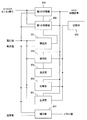
図1は、電源装置の一実施例を示す図である。図2は、電池ブロックと制御部の一実施例を示す図である。
制御部1(コンピュータ)は、例えば、Central Processing Unit(CPU)、マルチコアCPU、プログラマブルなデバイス(Field Programmable Gate Array(FPGA)、Programmable Logic Device(PLD)など)を用いることが考えられる。また、制御部1は記憶部を有してもよいし、制御部1とは別に設けた記憶部と接続してもよい。なお、制御部1に走行制御用ECUなどの機能を含んでいるものとする。
負荷2と補機3は、例えば、車両などに搭載される負荷である。負荷2は、インバータや駆動モータなどを示している。例えば、フォークリフトが走行するために電力が供給される負荷である。補機3は、例えば、フォークリフトの場合には機台側ECUや照明などの負荷の一部で、フォークリフトが駐車した場合でも電力を供給する負荷である。
キースイッチ4は車両を走行させるときに用いるスイッチで、例えば、イグニッションスイッチなどである。
メインスイッチSW1(第2のスイッチ)は負荷(負荷2、補機3)側へ電力を供給する電池ブロック6a、6b、6cとの接続を一括して行うスイッチである。メインスイッチSW1は、制御部1により接続(オン)と遮断(オフ)が制御される。メインスイッチSW1は、例えば、リレーなどを用いることが考えられる。ただし、メインスイッチSW1はなくてもよい。
制御スイッチ5はスイッチSW2a、SW2b、SW2c(第1のスイッチ)を有している。第1のスイッチSW2a、SW2b、SW2cは、並列に接続される電池ブロック6a、6b、6c各々に対して直列に接続される。第1のスイッチSW2a、SW2b、SW2cは、制御部1により接続(オン)と遮断(オフ)が制御され、例えば、リレーなどを用いることが考えられる。
電池ブロック6a、6b、6cについて図2を用いて説明する。
電池ブロック6aには電流計測部7a、電圧計測部8a1、8a2~8an、電池モジュール9a、電圧均等回路10a、温度計測部11aを有している。電池モジュール9aには電池Ba1、Ba2~Banが直列に接続されている。電池ブロック6bには電流計測部7b、電圧計測部8b1、8b2~8bn、電池モジュール9b、電圧均等回路10b、温度計測部11bを有している。電池モジュール9bには電池Bb1、Bb2~Bbnが直列に接続されている。電池ブロック6cには電流計測部7c、電圧計測部8c1、8c2~8cn、電池モジュール9c、電圧均等回路10c、温度計測部11cを有している。電池モジュール9cには電池Bc1、Bc2~Bcnが直列に接続されている。
電流計測部7a、7b、7cは電池モジュール9a、9b、9cから負荷側に流れる電流を計測する。電流計測部7a、7b、7cは、例えば、電流計である。計測した電流値各々は制御部1に送られる。
電圧計測部8a1、8a2~8an、8b1、8b2~8bn、8c1、8c2~8cnは、電池Ba1、Ba2~Ban、Bb1、Bb2~Bbn、Bc1、Bc2~Bcnの電圧を計測する。例えば、電圧計である。計測した電圧値各々は制御部1に送られる。
電池モジュール9aには複数の電池Ba1、Ba2~Banが直列に接続されている。電池モジュール9bには複数の電池Bb1、Bb2~Bbnが直列に接続されている。電池モジュール9cには複数の電池Bc1、Bc2~Bcnが直列に接続されている。電池Ba1、Ba2~Ban、電池Bb1、Bb2~Bbn、電池Bc1、Bc2~Bcnは二次電池などを用いることが考えられる。二次電池として、例えば、リチウムイオン二次電池、ニッケル水素二次電池などが考えられる。
電圧均等回路10a、10b、10cは、例えば、パッシブ型のセルバランス回路、トランス結合方式やコンバータ方式を含むアクティブ型のセルバランス回路、外部から電力を供給してセルバランスを行うプログレシブ型のセルバランス回路などが考えられる。本例では電圧均等回路の詳細について示していないが、パッシブ型のセルバランス回路の場合には電池モジュールに含まれる複数の電池のうちで最低電圧値の電池に、他の電池の電圧値を揃える回路である。すなわち、抵抗素子などを用いて他の電池の電力を消費させ、最低電圧値の電池に電圧値を揃える。
アクティブ型のセルバランス回路の場合には、電池モジュールの有する全ての電池の電圧値を、電池モジュール内の電池のエネルギーを移動させて均等にする回路である。トランス結合方式の場合にはトランスを用いてエネルギーの移動をさせて電圧値を均等にする。コンバータ方式の場合にはコイルを用いてエネルギーの移動をさせて電圧値を均等にする。
プログレッシブ型のセルバランス回路の場合には、外部に設置されている発電機などから電力の供給を受け、電池モジュールに含まれる複数の電池のうちで最大電圧値の電池に、他の電池の電圧値を揃える回路である。または、決められた電圧値に他の電池の電圧値を揃える回路である。
温度計測部11a、11b、11cは、電池モジュール9a、9b、9cの温度または電池Ba1、Ba2~Ban、Bb1、Bb2~Bbn、Bc1、Bc2~Bcnの各々の温度または決められた箇所の温度を計測し、制御部1に計測した温度値を送信する。
制御部について説明する。
図3は、制御部の一実施例を示す図である。制御部1は、特定部301、第1の切替部302、第2の切替部303、取得部304、推定部305、均等部306、補正部307、記憶部308などを有している。本例では、記憶部308は制御部1内に設けているが、制御部1と別に設けてもよい。
特定部301は、メインスイッチSW1、第1のスイッチSW2a、SW2b、SW2cが接続状態となり全ての電池モジュール9a、9b、9cから補機3に電流が流れているとき、電池モジュール9a、9b、9c各々の電圧値を求める。例えば、電池モジュール9aの電圧値は電圧計測部8a1、8a2~8anが計測した電圧値の合計値としてもよい。また、電圧計測部8a1、8a2~8anと別に電池Ba1の正極端子と電池Banの負極端子との間の電圧を計測する電圧計測部を設けて、計測した電圧値を電池モジュール9aの電圧値としてもよい。電池モジュール9b、9cについて同様に求めてよい。続いて、特定部301は求めた電池モジュール9a、9b、9c各々の電圧値のうち最大の電圧値である電池モジュールを特定する。
第1の切替部302は、負荷の一部である補機3にだけ電力を供給するとき、メインスイッチSW1と特定した電池モジュールに対応する第1のスイッチを接続状態にする。そして、特定した電池モジュール以外の電池モジュールに対応する第1のスイッチを全て遮断状態にする。ここで、負荷の一部である補機3にだけ電力を供給するときとは、車両のキースイッチ4がオフの状態で、車両が駐車している状態である。また、図2において特定した電池モジュールが電池モジュール9aである場合にはメインスイッチSW1と第1のスイッチSW2aを接続状態にし、電池モジュール9b、9cに対応する第1のスイッチSW2b、SW2cを遮断状態にする。
第2の切替部303は、補機3に電力を供給している電池モジュール(負荷の一部に電力を供給している第1の電池モジュール)の電圧値と、補機3に電力を供給していない電池モジュール(負荷の一部に電力を供給していない第2の電池モジュール)のうちで最大の電圧値と、の電圧差と閾値を比較する。電圧差が閾値より小さくなると、最大の電圧値の第2の電池モジュールに対応する第1のスイッチを接続状態にし、第1の電池モジュールに対応する第1のスイッチを遮断状態にする。
ここで、閾値は電池の許容電流値と、電池の内部抵抗値と、第1の電池モジュールと第2の電池モジュールに含まれる電池の数量との乗算により決まる値である。例えば、電池の許容電流値が200[A]、電池の内部抵抗値が1「mΩ」、第1の電池モジュールと第2の電池モジュールに含まれる電池の数量10個(電池モジュールひとつが有する電池の数量が5個)である場合、閾値は200×1m×10=2Vになる。
より正確には、電流が流れる系の配線抵抗と配線や電池を接続する接続部の抵抗も考慮に入れるとよい。
また、第1の電池モジュールが電池モジュール9aで、最大の電圧値の第2の電池モジュールが電池モジュール9bである場合、まず電池モジュール9bに対応する第1のスイッチSW2bを接続状態にする。その後、電池モジュール9aに対応する第1のスイッチSW2aを遮断状態にする。その結果、上記(4)に示したように、電池モジュールを切り替える際に、切り替える電池モジュール間に流れる還流電流が過大にならないようにできる。
取得部304は第2の電池モジュールの電池各々の開回路電圧値OCVを取得する。第1のスイッチSW2aが接続状態で、第1のスイッチSW2b、SW2cが遮断状態である場合、電池モジュール9b、9cに含まれる電池Bb1、Bb2~Bbn、Bc1、Bc2~Bcn各々の電圧を電圧計測部8b1、8b2~8bn、8c1、8c2~8cnから取得して、開回路電圧値OCVとする。取得した開回路電圧値OCVは記憶部308に記憶する。その結果、上記(1)に示したように、電池モジュールおよび電池の状態を知るための情報のひとつである電池モジュールおよび電池の開回路電圧値OCVを取得できる。
推定部305は、取得部304が取得した第2の電池モジュールの電池各々の開回路電圧値OCVを用いて充電の状態(SOC:充電率)を推定する。例えば、電池モジュール9bから取得した開回路電圧値OCVを用いて、図4に示す推定情報402を参照し、取得した開回路電圧値OCVに対応するSOCを選択する。図4は、OCVとSOCの関係を示す表と推定情報の一実施例を示す図である。図4の表401は縦軸にOCVを示し、横軸にSOCを示している。推定情報402は「開回路電圧OCV」「充電率SOC」に記憶される情報を有している。「開回路電圧OCV」には、電圧計測部により計測した開回路電圧値OCVを用いてSOCを推定する場合に用いる情報が記憶されている。本例では、電圧範囲として「OCV1」「OCV2」「OCV3」~「OCV21」などが記憶されている。
「充電率SOC」には、「開回路電圧OCV」に記憶されている電圧範囲を示す情報に対応するSOCを示す情報が記憶されている。本例では、SOCとして充電率100%を示す「100」、充電率95%を示す「95」などが記憶されている。その結果、上記(1)に示したように、電池モジュールおよび電池の状態を知るための情報のひとつである電池モジュールおよび電池のSOCを精度よく取得できる。すなわち、開回路にした電池モジュールの電池各々の開回路電圧値OCVを用いるので、電池モジュールから補機3に電流が流れている状態の回路(閉回路)の電流値、電圧値を用いてSOCを推定するより、SOC推定精度を向上させることができる。
均等部306は、第2の電池モジュールごとに第2の電池モジュールに含まれる電池の電圧を均等にする電圧均等回路10a、10b、10cを、制御する。例えば、第1のスイッチSW2b、SW2cが遮断状態である場合、電池モジュール9b、9cに対応する電圧均等回路10b、10cに、セルバランスを実行するための制御信号を出力する。その結果、上記(2)に示したように、電池モジュールに電流が流れていない状態をつくることにより、開回路にした電池モジュールに対してセルバランスを実行できる。
補正部307は、補機3(負荷の一部)に電力を供給するとき、開回路にした電池モジュールに対応する電流計測部のオフセット補正を行なう。すなわち、開回路にした電池モジュールから補機3には電流が流れなくなるため、上記(3)に示したように電流値0[A]におけるオフセット補正が可能となる。その結果、電流計測部7a、7b、7cの計測精度を向上させることができる。例えば、現在開回路になっている電池モジュール9b、9cの温度計測部11b、11cから送られてくる温度値が決められた温度であれば、その電池モジュール9b、9cに対応する温度計測部11b、11cにオフセット値を送ってオフセット補正を行う。
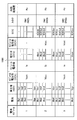
図5、図6は、実施形態1の動作の一実施例を示すフロー図である。図7は、実施形態1の状態情報のデータ構造の一実施例を示す図である。後述するステップS501~S512で求めた情報などは、図7に示す状態情報701に記憶される。状態情報701には、「電池モジュール」「電池」「電圧値(CCV)」「モジュール電圧値(CCV)」「モジュール電流値」「電圧値(OCV)」「モジュール電圧値(OCV)」「SOC」「スイッチ」に記憶する情報が記憶されている。「電池モジュール」には、電池モジュールを識別する情報が記憶されている。本例では、識別情報として「1」「2」「3」が記憶されている。「電池」には、電池を識別する情報が記憶されている。本例では、識別情報として「Ba1」「Ba2」「Ba3」・・・「Ban」「Bb1」「Bb2」「Bb3」・・・「Bbn」「Bc1」「Bc2」「Bc3」・・・「Bcn」が、電池モジュールを識別する情報に関連付けられて記憶されている。「電圧値(CCV)」には、補機3に電力を供給しているときの電圧値CCVが記憶されている。本例では、電池を識別する情報に関連付けられて電圧値CCVを示す情報「Va1」「Va2」「Va3」・・・「Van」「Vb1」「Vb2」「Vb3」・・・「Vbn」「Vc1」「Vc2」「Vc3」・・・「Vcn」が記憶されている。「モジュール電圧値(CCV)」には、補機3に電力を供給しているときの電池モジュールの電圧値が記憶されている。本例では、電池モジュールを識別する情報に関連付けられて電池モジュール電圧値CCVを示す情報「Vact」「Vbct」「Vcct」が記憶されている。「モジュール電流値」には、補機3に電力を供給しているときの電池モジュールの電流値が記憶されている。本例では、電池モジュールを識別する情報に関連付けられて電池モジュール電流値を示す情報「Iat」「Ibt」「Ict」が記憶されている。「電圧値(OCV)」には、駐車中(キースイッチ4がオフ中)に負荷2と補機3に電力を供給していない電池モジュールの電池の電圧値が記憶されている。本例では、電池を識別する情報に関連付けられて開回路電圧値OCVを示す情報「Vbo1」「Vbo2」「Vbo3」・・・「Vbon」「Vco1」「Vco2」「Vco3」・・・「Vcon」が記憶されている。なお、本例では識別情報「1」の電池モジュールは補機3に電力を供給しているため、開回路電圧値OCVを取得していない。「モジュール電圧値(OCV)」には、負荷2と補機3に電力を供給していない電池モジュールの電圧値が記憶されている。本例では、電池モジュールを識別する情報に関連付けられて電池モジュール電圧値を示す情報「Vbot」「Vcot」が記憶されている。なお、本例では識別情報「1」の電池モジュールは補機3に電力を供給しているため、電池モジュール電圧値はない。「SOC」には、推定部305が推定したSOCが電池を識別する情報に関連付けて記憶されている。本例では、電池を識別する情報に関連付けられてSOCを示す情報「SOCb1」「SOCb2」「SOCb3」・・・「SOCbn」「SOCc1」「SOCc2」「SOCc3」・・・「SOCcn」が記憶されている。なお、本例では識別情報「1」の電池モジュールは補機3に電力を供給しているため、識別情報「1」の電池モジュールのSOCは求めていない。「スイッチ」には、駐車中に電池モジュールが補機3に電力を供給するときに接続状態にするスイッチが記憶されている。本例では、電池モジュールの識別情報が「1」の電池モジュールに対して「SW1、Sw2a」、識別情報が「2」の電池モジュールに対して「SW1、Sw2b」、識別情報が「3」の電池モジュールに対して「SW1、Sw2c」が記憶されている。
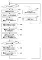
ステップS501では、キースイッチ4がオフか否かを制御部1が判定し、オフである場合(Yes)にはステップS502に移行し、オンである場合(No)にはステップS511に移行する。キースイッチ4がオフのとき、負荷2への電力は供給されない。
ステップS502では、制御部1が電池モジュール9a、9b、9cの電池Ba1、Ba2~Ban、Bb1、Bb2~Bbn、Bc1、Bc2~Bcnの分極が解消する時間だけ待ってステップS503に移行する。ここで、分極が解消する時間とは決められた時間で、例えば、実験により決めてもよいし、シミュレーションにより決定してもよい。ただし、分極の解消は完全にしなくてもよい。
ステップS503では、制御部1が電圧計測部8a1、8a2~8an、8b1、8b2~8bn、8c1、8c2~8cnから電池Ba1、Ba2~Ban、Bb1、Bb2~Bbn、Bc1、Bc2~Bcnの電圧値を取得する。そして、電池モジュール9a、9b、9c各々の電圧値を求める。ただし、電池モジュール9a、9b、9c各々の電圧を直接計測する電圧計測部を設けている場合には、その電圧計測部各々から電圧値を取得してもよい。
ステップS504では、制御部1の特定部301が電池モジュール9a、9b、9cのうち電圧値が最大の電池モジュールを特定する。特定した電池モジュールを電池モジュールm1(第1の電池モジュール)とし、電池モジュールm1の電圧値をVs1とする。
また、ステップS510からステップS501とステップS503を介してステップS504に移行してきた場合、特定部301は現在補機3に電力を供給している電池モジュールm1の電圧値と、他の電池モジュールの電圧値と、を比較して、電圧値が最大の電池モジュールを特定する。例えば、給電中の電池モジュール9aである場合には、電池モジュール9aの閉回路電圧値CCVと他の電池モジュール9b、9cの開回路電圧値OCVの中から電圧値が最大の電池モジュールを特定する。
ステップS505で制御部1の第1の切替部302は、特定した電池モジュールm1に対応する第1のスイッチを接続状態(オン)にし、特定した電池モジュールm1以外の第1のスイッチを遮断状態(オフ)にする。例えば、電池モジュールm1が電池モジュール9aである場合、第1のスイッチは電池モジュール9aに対応する第1のスイッチSW2aである。電池モジュール9a以外の電池モジュール9b、9cに対応する第1のスイッチは、スイッチSW2b、SW2cある。なお、この切り替えにおいても、補機3、電池モジュール9a、9b、9cに過大な電流が流れないよう考慮することが望ましい。
ステップS506では、制御部1が電池モジュールm1以外の電池モジュールに後述する第1の処理を実行する。第1の処理は、例えば、図6に示す処理などが考えられる。
ステップS507では、制御部1の第2の切替部303が電池モジュールm1以外の電池モジュール(第2の電池モジュール)のうちで電圧が最大の電池モジュールm2を特定する。電池モジュールm2の電圧値をVs2とする。すなわち、ステップS507では切り替える電池モジュールを特定する。
ステップS508では、第2の切替部303が電池モジュールm2の電圧値Vs2と電池モジュールm1の電圧値Vs1との電圧差が、閾値より小さいか否かを判定し、閾値より小さい場合(Vs2-Vs1<閾値:Yes)にはステップS509に移行する。閾値以上の場合(No)にはステップS508で閾値より小さくなるまで待つ。ここで、閾値は電池の許容電流値と、電池の内部抵抗値と、電池モジュールm1と電池モジュールm2に含まれる電池の数量と、を乗算した値である。
ステップS509では、第2の切替部303が電池モジュールm2に対応する第1のスイッチを接続状態(オン)にする。電池モジュールm2が電池モジュール9bである場合は第1のスイッチSW2bを接続状態にする。
ステップS510では、第2の切替部303が電池モジュールm1に対応する第1のスイッチを遮断状態(オフ)にする。電池モジュールm1が電池モジュール9aである場合は第1のスイッチSW2aを遮断状態(オフ)にする。
ステップS511では、キースイッチがオンであるので制御部1がメインスイッチと第1のスイッチをすべてオンにする。すなわち、スイッチSW1、SW2a、2b、2cを全て接続状態にして、全ての電池モジュール9a、9b、9cから負荷2と補機3に電力を供給する。この切り替えにおいても還流電流が過大にならないように考慮することが望ましい。
ステップS512では車両が走行する可能状態になる(車両動作処理)。
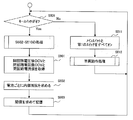
第1の処理について説明する。
ステップS601では、制御部の取得部304が第2の電池モジュールの開回路電圧値OCVを取得する。
ステップS602では、制御部の推定部305が開回路電圧値OCVを用いて第2の電池モジュールのSOCを推定する。
ステップS603では、制御部の均等部306が第2の電池モジュールのセルバランス処理を実行する。
ステップS604では、制御部の補正部307が第2の電池モジュールの電流計測部のオフセット補正を行う。
実施形態1によれば、補機3への電力供給を確保しつつ、精度よくSOCの推定ができる。また、セルバランス処理も実施できる。
電流を流してない状態の電池モジュールを用いて電池モジュールおよび電池の状態を知るための情報である開回路電圧値OCVを取得できるため、精度よくSOCを求められる。
電池モジュールに電流が流れていない状態をつくることにより、補機に電力を供給していない電池モジュールに対して精度のよい電池電圧の均等化処理(セルバランス処理)が行える。
電池モジュールに電流が流れていない状態をつくることにより、補機に電力を供給していない電池モジュールの電流を計測する電流計測部のオフセット補正を行うことができるため、電流計測部の計測精度を向上させることができる。
電池モジュールを切り替える際に、切り替える電池モジュール間の電圧差が決められた閾値より小さくなる切り替える側の電池モジュールを特定して切り替えをすることで、電池モジュール間に流れる還流電流が過大にならないようにできる。
さらに、キースイッチオフ中の励磁しているスイッチの数を減らせるため消費電力が低減される
実施形態2について説明する。
実施形態2について説明する。
図8は、実施形態2の制御部の一実施例を示す図である。実施形態2の制御部1は、特定部301、第1の切替部302、第2の切替部303、取得部304、推定部305、均等部306、補正部307、生成部801、記憶部308などを有している。本例では、記憶部308は制御部1内に設けているが、制御部1と別に設けてもよい。
生成部801は、第1の電池モジュールと、最大の電圧値の第2の電池モジュールと、に含まれる電池ごとに内部抵抗値を求め、求めた内部抵抗値を用いて閾値を求める。内部抵抗値は、例えば、電池ごとの開回路電圧値OCVと閉回路電圧値CCVとの電圧差と、閉回路電流値と、を用いて内部抵抗値を求め、電池の許容電流値と、第1の電池モジュールと第2の電池モジュールに含まれる電池各々の求めた内部抵抗値の合計値と、を乗算して閾値を求めることが考えられる。
図9は、実施形態2の制御部の一実施例を示すフロー図である。図10は、実施形態2の状態情報のデータ構造の一実施例を示す図である。後述するステップS501~S512とステップS901~S903で求めた情報などは、図10に示す状態情報1001に記憶される。状態情報1001には、「電池モジュール」「電池」「電圧値(CCV)」「モジュール電圧値(CCV)」「モジュール電流値」「電圧値(OCV)」「モジュール電圧値(OCV)」「SOC」「スイッチ」「内部抵抗値」に記憶する情報が記憶されている。状態情報1001と状態情報701との違いは「内部抵抗値」に記憶する情報である。「内部抵抗値」には生成部801で求めた内部抵抗値を示す情報が電池モジュールを識別する情報に関連付けられて記憶されている。本例では、内部抵抗値を示す情報「Ra」「Rb」「Rc」が記憶されている。
図9のステップS501~S512は実施形態1で説明したので省略する。
ステップS901では、制御部1の生成部801が電池ごとの開回路電圧値OCVと閉回路電圧値CCVと閉回路電流値とを取得する。
ステップS902では、制御部1の生成部801が電池ごとの開回路電圧値OCVと閉回路電圧値CCVとの電圧差と、閉回路電流値と、を用いて電池ごとの内部抵抗値を求める。なお、本例では状態情報1001に電池モジュールごとの内部抵抗値を求めて記憶している。
ステップS903では、電池の許容電流値と、第1の電池モジュールと第2の電池モジュールに含まれる電池各々の求めた内部抵抗値の合計値と、を乗算して閾値を求める。求めた閾値は記憶部308に記憶してもよい。
実施形態2によれば、補機3への電力供給を確保しつつ、精度よくSOCの推定ができる。また、セルバランス処理も実施できる。
電流を流してない状態の電池モジュールを用いて電池モジュールおよび電池の状態を知るための情報である開回路電圧値OCVを取得できるため、精度よくSOCを求められる。
電池モジュールに電流が流れていない状態をつくることにより、補機に電力を供給していない電池モジュールに対して精度のよい電池電圧の均等化処理(セルバランス処理)が行える。
電池モジュールに電流が流れていない状態をつくることにより、補機に電力を供給していない電池モジュールの電流を計測する電流計測部のオフセット補正を行うことができるため、電流計測部の計測精度を向上させることができる。
電池モジュールを切り替える際に、切り替える電池モジュール間の電圧差が決められた閾値より小さくなる切り替える側の電池モジュールを特定して切り替えをすることで、電池モジュール間に流れる還流電流が過大にならないようにできる。
さらに、キースイッチオフ中の励磁しているスイッチの数を減らせるため消費電力が低減される
また、本発明は、上記実施の形態に限定されるものでなく、本発明の要旨を逸脱しない範囲内で種々の改良、変更が可能である。
また、本発明は、上記実施の形態に限定されるものでなく、本発明の要旨を逸脱しない範囲内で種々の改良、変更が可能である。
例えば、特定部301が電圧値が最大の電池モジュールを特定するのは、補機3に電流が流れているときに限らず、負荷2と補機3に電流が流れていないときでも良い。使用するアプリケーションによっては、キースイッチ4をオフにしたときでも補機3に電流が流れない場合がある。この場合、負荷2と補機3に電流が流れていないときの電池モジュール9a、9b、9cのうち電圧値が最大の電池モジュールを特定する。また、特定部301が電圧値が最大の電池モジュールを特定するのは、キースイッチがオフになる直前でも良い。この場合、キースイッチがオンになっている間に定期的に電池モジュール9a、9b、9cの電圧値を取得し、キースイッチがオフになったときに、直前に取得した電圧値をもとに特定する。
また、例えば、補機3に電力を供給するために特定される電池モジュール(第1の電池モジュール)は、電圧値が最大のものに限らず、任意のモジュールとしても良い。即ち、特定部301は電力を供給する電池モジュール(第1の電池モジュール)を電圧値に関係なく特定しても良い。例えば、ランダムまたは並列モジュールの接続順に電池モジュールを特定することが考えられる。この場合、第2の切替部がランダムまたは並列モジュールの接続順に次に接続する電池モジュールを特定しても良い。この場合でも上記(1)(2)(3)の効果を奏する。
また、例えば、補機3に電力を供給する電池モジュールは複数でも良い。例えば、並列数が6のときに、補機3に電力を供給されるために特定される電池モジュール(第1の電池モジュール)は、2つでも良い。この場合でも上記(1)(2)(3)の効果を奏する。
Claims (8)
- 複数の電池が直列に接続される複数の電池モジュールと、
前記電池の電圧を計測するための電圧計測部と、
並列に接続される前記電池モジュール各々に対して直列に接続される複数の第1のスイッチと、
前記電池モジュールを特定する特定部と、
キースイッチがオフで負荷の一部に電力を供給するとき、特定した前記電池モジュールに対応する前記第1のスイッチを接続状態にし、特定した前記電池モジュール以外の電池モジュールに対応する前記第1のスイッチを全て遮断状態にする第1の切替部と、
前記負荷の一部に電力を供給していない前記電池モジュールである第2の電池モジュールに対応する前記第1のスイッチを接続状態にし、前記第1の電池モジュールに対応する前記第1のスイッチを遮断状態にする第2の切替部と、
前記負荷の一部に電力を供給していない前記第2の電池モジュールの前記電池各々の開回路電圧を取得する取得部と、
を備えることを特徴とする電源装置。 - 前記負荷の一部に電力を供給していない前記第2の電池モジュールごとに前記第2の電池モジュールに含まれる前記電池の電圧を均等にする電圧均等回路を、制御する均等部を備えることを特徴とする請求項1に記載の電源装置。
- 前記特定部は、
前記電池モジュール各々の電圧値を求め、求めた前記電圧値のうち最大の電圧値である電池モジュールを特定し、
前記第2の切替部は、
前記負荷の一部に電力を供給している前記電池モジュールである第1の電池モジュールの電圧値と、前記負荷の一部に電力を供給していない前記電池モジュールである第2の電池モジュールのうちで最大の電圧値と、の電圧差を求め、
決められた閾値より前記電圧差が小さくなると、前記最大の電圧値の第2の電池モジュールに対応する前記第1のスイッチを接続状態にし、前記第1の電池モジュールに対応する前記第1のスイッチを遮断状態にする、
ことを特徴とする請求項1または2に記載の電源装置。 - 前記閾値は、前記電池の許容電流値と、前記電池の内部抵抗値と、前記第1の電池モジュールと前記第2の電池モジュールに含まれる前記電池の数量と、の乗算により決まることを特徴とする請求項3に記載の電源装置。
- 前記取得部が取得した前記第2の電池モジュールの前記電池各々の前記開回路電圧を用いて充電状態の推定する推定部を備える、ことを特徴とする請求項1~4のいずれか1つに記載の電源装置。
- 前記負荷の一部に電力を供給するとき、前記第2の電池モジュールに対応する前記電流計測部のオフセット補正を行なう補正部を備える、ことを特徴とする請求項5に記載の電源装置。
- 前記第1の電池モジュールと、最大の電圧値の前記第2の電池モジュールと、に含まれる前記電池ごとに内部抵抗値を求め、求めた前記内部抵抗を用いて前記閾値を求める生成部を備える、ことを特徴とする請求項3または4に記載の電源装置。
- 並列に接続される、複数の電池が直列に接続される電池モジュール各々に対して直列に接続される複数の第1のスイッチ全てが接続状態のとき、全ての前記電池モジュールから負荷に電流が流れているとき、前記電池モジュール各々の電圧値を求め、求めた前記電圧値のうち最大の電圧値である電池モジュールを特定し、
前記負荷の一部に電力を供給するとき、特定した前記電池モジュールに対応する前記第1のスイッチを接続状態にし、特定した前記電池モジュール以外の電池モジュールに対応する前記第1のスイッチを全て遮断状態にし、
前記負荷の一部に電力を供給している前記電池モジュールである第1の電池モジュールの電圧値と、前記負荷の一部に電力を供給していない前記電池モジュールである第2の電池モジュールのうちで最大の電圧値と、の電圧差を求め、
前記電池の許容電流値と、前記電池の内部抵抗値と、前記第1の電池モジュールと前記第2の電池モジュールに含まれる前記電池の数量と、の乗算により決まる閾値より、前記電圧差が小さくなると、前記最大の電圧値の第2の電池モジュールに対応する前記第1のスイッチを接続状態にし、前記第1の電池モジュールに対応する前記第1のスイッチを遮断状態にし、
前記負荷の一部に電力を供給していない前記第2の電池モジュールの前記電池各々の開回路電圧を取得する、
ことを特徴とする電池モジュール切り替え方法。
Applications Claiming Priority (2)
| Application Number | Priority Date | Filing Date | Title |
|---|---|---|---|
| JP2012219560A JP5892024B2 (ja) | 2012-10-01 | 2012-10-01 | 電源装置および電池モジュール切り替え方法 |
| JP2012-219560 | 2012-10-01 |
Publications (1)
| Publication Number | Publication Date |
|---|---|
| WO2014054368A1 true WO2014054368A1 (ja) | 2014-04-10 |
Family
ID=50434700
Family Applications (1)
| Application Number | Title | Priority Date | Filing Date |
|---|---|---|---|
| PCT/JP2013/073657 WO2014054368A1 (ja) | 2012-10-01 | 2013-09-03 | 電源装置および電池モジュール切り替え方法 |
Country Status (2)
| Country | Link |
|---|---|
| JP (1) | JP5892024B2 (ja) |
| WO (1) | WO2014054368A1 (ja) |
Cited By (7)
| Publication number | Priority date | Publication date | Assignee | Title |
|---|---|---|---|---|
| WO2016006462A1 (ja) * | 2014-07-07 | 2016-01-14 | 日立オートモティブシステムズ株式会社 | 電池制御装置 |
| CN108983104A (zh) * | 2018-07-13 | 2018-12-11 | 福建和盛高科技产业有限公司 | 一种基于电池开路电压法在线容量计算方法 |
| CN109849694A (zh) * | 2019-03-26 | 2019-06-07 | 中车唐山机车车辆有限公司 | 一种基于在线凸规划的混合储能式有轨电车能量管理方法 |
| CN109955732A (zh) * | 2017-12-14 | 2019-07-02 | 丰田自动车株式会社 | 车辆的充电装置 |
| CN111130163A (zh) * | 2018-10-31 | 2020-05-08 | 丰田自动车株式会社 | 电源系统 |
| CN113454830A (zh) * | 2019-04-02 | 2021-09-28 | 株式会社今仙电机制作所 | 二次电芯系统 |
| WO2022097307A1 (ja) * | 2020-11-09 | 2022-05-12 | 東芝三菱電機産業システム株式会社 | 電力変換装置の制御装置および電力変換装置用抵抗器 |
Families Citing this family (10)
| Publication number | Priority date | Publication date | Assignee | Title |
|---|---|---|---|---|
| WO2016147614A1 (ja) * | 2015-03-16 | 2016-09-22 | 日本電気株式会社 | 蓄電池装置、及び、容量補正方法 |
| JP6570063B2 (ja) * | 2015-09-04 | 2019-09-04 | ニチコン株式会社 | 給電装置 |
| CN107591572A (zh) * | 2016-07-06 | 2018-01-16 | 深圳市沃特玛电池有限公司 | 电池管理系统采集模块自动编号系统及方法 |
| WO2018051866A1 (ja) | 2016-09-14 | 2018-03-22 | 富士電機株式会社 | 鉛蓄電池装置、鉛蓄電池の制御装置、鉛蓄電池の制御方法 |
| KR102167428B1 (ko) | 2016-10-21 | 2020-10-20 | 주식회사 엘지화학 | 듀티 제어를 통한 효과적인 배터리 셀 밸런싱 방법 및 시스템 |
| JP6775431B2 (ja) | 2017-01-23 | 2020-10-28 | 株式会社デンソーテン | 蓄電装置および蓄電制御方法 |
| JP6775435B2 (ja) | 2017-01-31 | 2020-10-28 | 株式会社デンソーテン | 蓄電装置および蓄電制御方法 |
| JP6802723B2 (ja) | 2017-01-31 | 2020-12-16 | 株式会社デンソーテン | 蓄電装置および蓄電制御方法 |
| JP7401216B2 (ja) * | 2019-07-26 | 2023-12-19 | 株式会社デンソーテン | 均等化装置及び均等化方法 |
| CN112290647B (zh) * | 2020-11-19 | 2022-05-27 | 厦门西海佳通信息科技有限公司 | 一种电池供电系统及其方法 |
Citations (2)
| Publication number | Priority date | Publication date | Assignee | Title |
|---|---|---|---|---|
| JP2009033936A (ja) * | 2007-07-30 | 2009-02-12 | Toshiba Corp | 並列接続蓄電システム |
| WO2011155014A1 (ja) * | 2010-06-07 | 2011-12-15 | トヨタ自動車株式会社 | 車両の電力制御装置および車両の電力制御方法 |
Family Cites Families (6)
| Publication number | Priority date | Publication date | Assignee | Title |
|---|---|---|---|---|
| JP3890168B2 (ja) * | 1999-08-03 | 2007-03-07 | 株式会社東京アールアンドデー | 電動装置及びその電池ユニットの充放電方法 |
| JP2004025979A (ja) * | 2002-06-25 | 2004-01-29 | Shin Kobe Electric Mach Co Ltd | 走行車両用電源システム |
| JP5529402B2 (ja) * | 2008-08-13 | 2014-06-25 | 三菱重工業株式会社 | 蓄電システム |
| JP2011015473A (ja) * | 2009-06-30 | 2011-01-20 | Toyota Motor Corp | 電源システムおよびそれを備えた電動車両ならびに電源システムの制御方法 |
| JP2011072153A (ja) * | 2009-09-28 | 2011-04-07 | Sanyo Electric Co Ltd | 車両用電源装置及びこれを備える車両並びに車両用電源装置の容量均等化方法 |
| JP5633478B2 (ja) * | 2011-06-27 | 2014-12-03 | 株式会社デンソー | 蓄電池 |
-
2012
- 2012-10-01 JP JP2012219560A patent/JP5892024B2/ja active Active
-
2013
- 2013-09-03 WO PCT/JP2013/073657 patent/WO2014054368A1/ja active Application Filing
Patent Citations (2)
| Publication number | Priority date | Publication date | Assignee | Title |
|---|---|---|---|---|
| JP2009033936A (ja) * | 2007-07-30 | 2009-02-12 | Toshiba Corp | 並列接続蓄電システム |
| WO2011155014A1 (ja) * | 2010-06-07 | 2011-12-15 | トヨタ自動車株式会社 | 車両の電力制御装置および車両の電力制御方法 |
Cited By (15)
| Publication number | Priority date | Publication date | Assignee | Title |
|---|---|---|---|---|
| US10554064B2 (en) | 2014-07-07 | 2020-02-04 | Hitachi Automotive Systems, Ltd. | Battery controlling device |
| JPWO2016006462A1 (ja) * | 2014-07-07 | 2017-04-27 | 日立オートモティブシステムズ株式会社 | 電池制御装置 |
| JP2017209006A (ja) * | 2014-07-07 | 2017-11-24 | 日立オートモティブシステムズ株式会社 | 電池制御装置 |
| WO2016006462A1 (ja) * | 2014-07-07 | 2016-01-14 | 日立オートモティブシステムズ株式会社 | 電池制御装置 |
| US10205333B2 (en) | 2014-07-07 | 2019-02-12 | Hitachi Automotive Systems, Ltd. | Battery controlling device |
| CN109955732B (zh) * | 2017-12-14 | 2022-06-24 | 丰田自动车株式会社 | 车辆的充电装置 |
| CN109955732A (zh) * | 2017-12-14 | 2019-07-02 | 丰田自动车株式会社 | 车辆的充电装置 |
| CN108983104A (zh) * | 2018-07-13 | 2018-12-11 | 福建和盛高科技产业有限公司 | 一种基于电池开路电压法在线容量计算方法 |
| CN111130163A (zh) * | 2018-10-31 | 2020-05-08 | 丰田自动车株式会社 | 电源系统 |
| CN109849694B (zh) * | 2019-03-26 | 2020-07-24 | 中车唐山机车车辆有限公司 | 一种基于在线凸规划的混合储能式有轨电车能量管理方法 |
| CN109849694A (zh) * | 2019-03-26 | 2019-06-07 | 中车唐山机车车辆有限公司 | 一种基于在线凸规划的混合储能式有轨电车能量管理方法 |
| CN113454830A (zh) * | 2019-04-02 | 2021-09-28 | 株式会社今仙电机制作所 | 二次电芯系统 |
| WO2022097307A1 (ja) * | 2020-11-09 | 2022-05-12 | 東芝三菱電機産業システム株式会社 | 電力変換装置の制御装置および電力変換装置用抵抗器 |
| JPWO2022097307A1 (ja) * | 2020-11-09 | 2022-05-12 | ||
| JP7332042B2 (ja) | 2020-11-09 | 2023-08-23 | 東芝三菱電機産業システム株式会社 | 電力変換装置の制御装置および電力変換システム |
Also Published As
| Publication number | Publication date |
|---|---|
| JP5892024B2 (ja) | 2016-03-23 |
| JP2014073051A (ja) | 2014-04-21 |
Similar Documents
| Publication | Publication Date | Title |
|---|---|---|
| JP5892024B2 (ja) | 電源装置および電池モジュール切り替え方法 | |
| US9496727B2 (en) | Characterizing a rechargeable battery through discontinuous charging | |
| CN109313236B (zh) | 用于校准电池的充电状态的电池管理装置和方法 | |
| Zheng et al. | On-line equalization for lithium-ion battery packs based on charging cell voltages: Part 1. Equalization based on remaining charging capacity estimation | |
| Rothgang et al. | Modular battery design for reliable, flexible and multi-technology energy storage systems | |
| JP5274110B2 (ja) | 車両用の電源装置 | |
| JP6179407B2 (ja) | 組電池の均等化装置及び方法 | |
| JP5499200B2 (ja) | 劣化判定装置、劣化判定方法、及びプログラム | |
| US9197080B2 (en) | Electric storage device management apparatus | |
| US9225180B2 (en) | Electric storage device management apparatus and method of equalizing capacities of electric storage devices | |
| WO2012157747A1 (ja) | 組電池の制御方法及び制御装置 | |
| JPWO2018056263A1 (ja) | 電源システム | |
| JP7471337B2 (ja) | 直列接続電池セルのための監視システム | |
| JP5727016B2 (ja) | 電池制御装置 | |
| CN104937431A (zh) | 充电率估计装置及充电率估计方法 | |
| JP2015080334A (ja) | 蓄電システム | |
| WO2012132160A1 (ja) | 劣化測定装置、二次電池パック、劣化測定方法、およびプログラム | |
| WO2014126029A1 (ja) | 充電率推定装置および充電率推定方法 | |
| JP6618443B2 (ja) | 電源システムの充電停止方法 | |
| WO2015178075A1 (ja) | 電池制御装置 | |
| JP2013121242A (ja) | Soc推定装置及び電池パック | |
| JP2018125977A (ja) | 電池モジュールの制御装置 | |
| JP6770184B2 (ja) | 電源システム、電源システムの故障診断方法およびシステム制御装置 | |
| JP6086487B2 (ja) | 電池状態検出装置 | |
| JP2016181991A (ja) | 充電装置および充電装置の制御方法 |
Legal Events
| Date | Code | Title | Description |
|---|---|---|---|
| 121 | Ep: the epo has been informed by wipo that ep was designated in this application |
Ref document number: 13844224 Country of ref document: EP Kind code of ref document: A1 |
|
| NENP | Non-entry into the national phase |
Ref country code: DE |
|
| 122 | Ep: pct application non-entry in european phase |
Ref document number: 13844224 Country of ref document: EP Kind code of ref document: A1 |