WO2014050302A1 - Station de base radio, terminal utilisateur, système et procédé de radiocommunication - Google Patents
Station de base radio, terminal utilisateur, système et procédé de radiocommunication Download PDFInfo
- Publication number
- WO2014050302A1 WO2014050302A1 PCT/JP2013/070785 JP2013070785W WO2014050302A1 WO 2014050302 A1 WO2014050302 A1 WO 2014050302A1 JP 2013070785 W JP2013070785 W JP 2013070785W WO 2014050302 A1 WO2014050302 A1 WO 2014050302A1
- Authority
- WO
- WIPO (PCT)
- Prior art keywords
- search space
- extended
- control channel
- user terminal
- base station
- Prior art date
Links
Images


Classifications
-
- H—ELECTRICITY
- H04—ELECTRIC COMMUNICATION TECHNIQUE
- H04L—TRANSMISSION OF DIGITAL INFORMATION, e.g. TELEGRAPHIC COMMUNICATION
- H04L1/00—Arrangements for detecting or preventing errors in the information received
- H04L1/004—Arrangements for detecting or preventing errors in the information received by using forward error control
- H04L1/0045—Arrangements at the receiver end
- H04L1/0046—Code rate detection or code type detection
-
- H—ELECTRICITY
- H04—ELECTRIC COMMUNICATION TECHNIQUE
- H04W—WIRELESS COMMUNICATION NETWORKS
- H04W72/00—Local resource management
- H04W72/20—Control channels or signalling for resource management
- H04W72/23—Control channels or signalling for resource management in the downlink direction of a wireless link, i.e. towards a terminal
-
- H—ELECTRICITY
- H04—ELECTRIC COMMUNICATION TECHNIQUE
- H04B—TRANSMISSION
- H04B7/00—Radio transmission systems, i.e. using radiation field
- H04B7/02—Diversity systems; Multi-antenna system, i.e. transmission or reception using multiple antennas
- H04B7/04—Diversity systems; Multi-antenna system, i.e. transmission or reception using multiple antennas using two or more spaced independent antennas
- H04B7/0413—MIMO systems
- H04B7/0452—Multi-user MIMO systems
-
- H—ELECTRICITY
- H04—ELECTRIC COMMUNICATION TECHNIQUE
- H04L—TRANSMISSION OF DIGITAL INFORMATION, e.g. TELEGRAPHIC COMMUNICATION
- H04L1/00—Arrangements for detecting or preventing errors in the information received
- H04L1/004—Arrangements for detecting or preventing errors in the information received by using forward error control
- H04L1/0072—Error control for data other than payload data, e.g. control data
-
- H—ELECTRICITY
- H04—ELECTRIC COMMUNICATION TECHNIQUE
- H04L—TRANSMISSION OF DIGITAL INFORMATION, e.g. TELEGRAPHIC COMMUNICATION
- H04L27/00—Modulated-carrier systems
- H04L27/26—Systems using multi-frequency codes
- H04L27/2601—Multicarrier modulation systems
- H04L27/2626—Arrangements specific to the transmitter only
- H04L27/2627—Modulators
- H04L27/2643—Modulators using symbol repetition, e.g. time domain realization of distributed FDMA
-
- H—ELECTRICITY
- H04—ELECTRIC COMMUNICATION TECHNIQUE
- H04L—TRANSMISSION OF DIGITAL INFORMATION, e.g. TELEGRAPHIC COMMUNICATION
- H04L5/00—Arrangements affording multiple use of the transmission path
- H04L5/003—Arrangements for allocating sub-channels of the transmission path
- H04L5/0053—Allocation of signaling, i.e. of overhead other than pilot signals
-
- H—ELECTRICITY
- H04—ELECTRIC COMMUNICATION TECHNIQUE
- H04W—WIRELESS COMMUNICATION NETWORKS
- H04W88/00—Devices specially adapted for wireless communication networks, e.g. terminals, base stations or access point devices
- H04W88/02—Terminal devices
-
- H—ELECTRICITY
- H04—ELECTRIC COMMUNICATION TECHNIQUE
- H04W—WIRELESS COMMUNICATION NETWORKS
- H04W88/00—Devices specially adapted for wireless communication networks, e.g. terminals, base stations or access point devices
- H04W88/08—Access point devices
Definitions
- the present invention relates to a radio base station, a user terminal, a radio communication system, and a radio communication method in a next generation radio communication system.
- LTE Long Term Evolution
- OFDMA Orthogonal Frequency Division Multiple Access
- SC-FDMA Single Carrier Frequency Division Multiple Access
- LTE-A LTE Advanced or LTE enhancement
- MIMO Multi Input Multi Output
- a plurality of transmission / reception antennas are prepared in a transceiver, and different transmission information sequences are transmitted simultaneously from different transmission antennas.
- MU-MIMO multi-user MIMO
- Hetnet Heterogeneous network
- CoMP Coordinatd Multi-Point
- the problem is how to configure search space candidates used for blind decoding of downlink control information.
- the present invention has been made in view of the above points, and when extending a radio resource region for a downlink control channel, a radio base station capable of appropriately configuring search space candidates used for blind decoding of downlink control information, It is an object to provide a user terminal, a wireless communication system, and a wireless communication method.
- the radio base station of the present invention is a radio base station that transmits downlink control information for a user terminal using an extended downlink control channel that is frequency-division-multiplexed to a downlink shared data channel.
- a setting unit that sets a plurality of resource sets each including a plurality of resource blocks allocated to the extended downlink control channel, and a plurality of search space candidates of each resource set are arranged in different resource blocks.
- a user terminal is a user terminal that receives downlink control information from a radio base station using an extended downlink control channel that is frequency-division multiplexed to a downlink shared data channel, and a plurality of terminals that are assigned to the extended downlink control channel.
- a plurality of resource sets each including a plurality of resource blocks are set in the user terminal, a determination unit that determines an extended control channel element constituting a plurality of search space candidates of each resource set, and the extension
- An acquisition unit that performs blind decoding on a control channel element to acquire the downlink control information, and the plurality of search space candidates are respectively arranged in different resource blocks constituting each resource set.
- search space candidates used for blind decoding of downlink control information can be appropriately configured when extending the radio resource region for the downlink control channel.
- 1 is a schematic diagram of a radio communication system to which MU-MIMO is applied. It is a figure which shows an example of the sub-frame by which downlink MU-MIMO transmission is performed. It is explanatory drawing of the sub-frame structure of extended PDCCH. It is explanatory drawing of the mapping method of extended PDCCH. It is a figure which shows an example of the dispersion
- FIG. 1 is a diagram illustrating an example of a wireless communication system to which MU-MIMO transmission is applied.
- the system shown in FIG. 1 has a hierarchical configuration in which small base stations (for example, RRH: Remote Radio Head, etc.) having a local coverage area are provided within the coverage area of a radio base station (for example, eNB: eNodeB).
- a radio base station for example, eNB: eNodeB
- UE User Equipment
- # 2 data for a plurality of user terminals UE # 1 and # 2 are simultaneously transmitted from a plurality of antennas of a radio base station.
- data for a plurality of user terminals UE # 3 and # 4 are simultaneously transmitted from a plurality of antennas of a plurality of small base stations.
- FIG. 2 is a diagram illustrating an example of a radio frame (for example, one subframe) to which downlink MU-MIMO transmission is applied.
- radio resources for a downlink control channel (PDCCH: Physical Downlink Control Channel) from the beginning to a predetermined OFDM symbol (maximum 3 OFDM symbols) in each subframe. It is secured as a region (PDCCH region).
- PDSCH area for a downlink shared data channel (PDSCH: Physical Downlink Shared Channel) is secured in radio resources after a predetermined symbol from the top of the subframe.
- DCI Downlink Control Information
- UE # 1 to # 4 Downlink Control Information
- DCI includes data allocation information for the user terminal UE in the PDSCH region.
- the user terminal UE # 2 receives data for the user terminal UE # 2 assigned to the PDSCH region based on the DCI for the user terminal UE # 2 assigned to the PDCCH region.
- DCI allocation areas cannot be secured for all user terminals UE # 1 to # 6 in the PDCCH area.
- DCI for user terminals UE # 5 and # 6 cannot be assigned.
- the effect of improving the use efficiency of radio resources by MU-MIMO transmission may not be sufficiently obtained .
- the PDCCH allocation region is expanded from the beginning of the subframe to a control region other than a maximum of 3 OFDM symbols (the PDCCH region is expanded to an existing PDSCH region after 4 OFDM symbols). Can be considered.
- a method for extending the PDCCH region as shown in FIG. 3A, a method of time-division multiplexing PDSCH and PDCCH in the existing PDSCH region (TDM approach), as shown in FIG. 3B, PDSCH and PDCCH in the existing PDSCH region. And frequency division multiplexing (FDM approach).
- PDCCHs are arranged over the entire system band in some OFDM symbols after 4 OFDM symbols in a subframe.
- PDCCH is arranged in a part of the system band in all OFDM symbols after 4 OFDM symbols in a subframe.
- the PDCCH frequency-division multiplexed with the PDSCH by this FDM approach is demodulated using a demodulation reference signal (DM-RS: DeModulation-Reference Signal) which is a user-specific reference signal.
- DM-RS DeModulation-Reference Signal
- an extended PDCCH enhanced PDCCH
- This extended PDCCH may be called an enhanced downlink control channel (Enhanced Physical Downlink Control CHannel), ePDCCH, E-PDCCH, FDM type PDCCH, UE-PDCCH, or the like.
- Enhanced Physical Downlink Control CHannel Enhanced Physical Downlink Control CHannel
- ePDCCH E-PDCCH
- FDM type PDCCH UE-PDCCH
- FIG. 4 is a diagram for explaining a DCI mapping method in the extended PDCCH.
- FIG. 4A shows local mapping and
- FIG. 4B shows distributed mapping.
- the extended PDCCH is composed of a predetermined number of physical resource block (PRB) pairs distributed in the system band.
- the PRB pair is composed of two PRBs continuous in the time direction, and is identified by a PRB index given in the frequency direction.
- a plurality of PRB pairs constituting the extended PDCCH are determined by higher layers.
- the PRB index for identifying each of the plurality of PRB pairs is notified to the user terminal UE by higher layer signaling.
- a plurality of PRB pairs constituting the extended PDCCH may be determined in advance by specifications.
- 1DCI is locally mapped to a specific PRB pair constituting the extended PDCCH.
- 1DCI is mapped into a predetermined number of PRB pairs (for example, 1 or 2 PRB pairs with good channel quality) based on channel quality information (for example, CQI) fed back from the user terminal UE.
- channel quality information for example, CQI
- PDSCH may be mapped to a PRB pair to which DCI is not mapped among a plurality of PRB pairs constituting the extended PDCCH.
- 1DCI is distributed and mapped to a plurality of PRB pairs constituting the extended PDCCH. Specifically, 1DCI is divided into a plurality of divided units, and each divided unit is distributed and mapped to the plurality of PRB pairs (may be all PRB pairs).
- frequency diversity gain can be obtained by dispersing 1DCI in the system band.
- each DCI is divided into a plurality of divided units, and each divided unit is distributed and mapped to a plurality of PRB pairs constituting the extended PDCCH.
- the extended PDCCH is composed of many PRB pairs (eight PRB pairs in FIG. 5A)
- the utilization efficiency of radio resources decreases. This is because 1DCI division units are distributed and mapped to many PRB pairs, and the number of PRB pairs to which PDSCH can be mapped decreases.
- the distributed mapping as shown in FIG. 5B, it is considered to limit the number of PRB pairs to which 1DCI divided units are mapped in a distributed manner.
- the number of PRB pairs to which 1DCI division units are distributed and mapped is limited to four.
- the number of PRB pairs to which the PDSCH can be mapped increases as compared to the case illustrated in FIG. 5A.
- each extended PDCCH set includes a plurality of PRB pairs assigned to the extended PDCCH.
- the extended PDCCH set may be called an enhanced PDCCH set, an ePDCCH set, an E-PDCCH set, or simply a set.
- extended PDCCH sets # 1 and # 2 are set redundantly for each of user terminals UE # 1- # 10.
- the number of user terminals UE to which DCI is transmitted is less than a predetermined number, since DCI is mapped only to one extended PDCCH set # 1, the other extended PDCCH # 2 can be used for PDSCH. It becomes.
- wireless resource can be improved by setting a some extended PDCCH set redundantly with respect to each user terminal UE.
- each user terminal UE blind-decodes search space candidates of extended PDCCH sets # 1 and # 2.
- the search space per extended PDCCH set is set so that the number of search space candidates in the extended PDCCH sets # 1 and # 2 as a whole does not increase as compared with the case where no extended PDCCH set is provided.
- the number of candidates may be set.
- DCI may be distributedly mapped (see FIG. 4B and FIG. 5) or locally mapped (see FIG. 4A).
- a plurality of search space candidates of the extended PDCCH set are arranged in different PRB pairs constituting the extended PDCCH set. Is desirable.
- FIGS. 6A and 6B in the case of aggregation level 1 of the extended PDCCH set # 1, three search space candidates are provided.
- these three search space candidates are arranged in different 3PRB pairs # 1, # 8, and # 15 in FIG. 6A, DCI is mapped to the search space candidates arranged in PRB pair # 15 having the best channel quality. By doing so, a frequency scheduling gain can be obtained.
- each search space candidate in the extended PDCCH set is preferably configured with random ECCE for each subframe. That is, it is desirable that the ECCE index numbers constituting each search space candidate are random for each subframe.
- DCI when DCI is locally mapped in the extended PDCCH set, it is desired to configure search space candidates so that a frequency scheduling gain can be obtained. It is also desired to configure search space candidates so that the blocking probability can be reduced.
- FIG. 7 and 8 are diagrams for explaining a configuration example of a search space when DCI is locally mapped in the extended PDCCH set.
- the number of search space candidates per one extended PDCCH set is set so that the number of times of blind decoding in the user terminal UE does not increase compared to the case where no extended PDCCH set is provided.
- the ECCE constituting the search space candidate of each extended PDCCH set is determined based on, for example, a hash function shown in Expression (1).
- N ECCE is the total number of ECCEs per extended PDCCH set (8 in FIG. 7).
- L is an aggregation level.
- i 0,..., L-1.
- Y k in equation (1) is defined by equation (2).
- k is a parameter that is different for each subframe.
- the number of search space candidates when no extended PDCCH set is provided is “2”. Therefore, search space candidates cannot be provided in all of the extended PDCCH sets 1-6.
- a PRB pair is randomly selected based on C-RNTI (Cell-Radio Network Temporary ID) or the like, and a search space candidate is configured by ECCE in the selected PRB pair.
- the six search space candidates of the extended PDCCH set 1-6 are different PRBs. Arranged in pairs. For this reason, a frequency scheduling gain can be obtained by using the search space candidate of the extended PDCCH set arranged in the PRB pair with good channel quality.
- the number of search space candidates when no extended PDCCH set is provided is “6”
- the number of search space candidates for extended PDCCH sets 1 and 2 is “3”, respectively.
- the ECCE configuring the search space candidates of each extended PDCCH set is determined based on, for example, the hash function shown in Equation (1), the three search space candidates of each extended PDCCH set are not arranged in different PRB pairs. There is a case.
- the first search space candidate of the extended PDCCH set 1 is determined as ECCE # 0 at the aggregation level 1 by the above formula (1).
- the second and third search space candidates of the extended PDCCH set 1 are determined as ECCE # 1 and # 2, respectively.
- ECCE # 0- # 3 of extended PDCCH set 1 are all included in PRB pair # 0.
- all three search space candidates of the extended PDCCH set 1 are arranged in the same PRB pair # 0.
- the first search space candidate of the extended PDCCH set 2 is determined as ECCE # 7 at the aggregation level 1 by the above formula (1).
- the second and third search space candidates of the extended PDCCH set 2 are determined as ECCE # 8 and # 9, respectively.
- ECCE # 7 of extended PDCCH set 2 is included in PRB pair # 10
- ECCE # 8 and # 9 are included in PRB pair # 27.
- the two search space candidates of the extended PDCCH set 2 are arranged in the same PRB pair # 27.
- the present inventors have a case where the number of extended PDCCH sets set for each user terminal UE is smaller than the number of search space candidates when no extended PDCCH set is provided (for example, K ⁇ 6 Case), a search space candidate configuration method capable of obtaining a frequency scheduling gain by local mapping of DCI was studied, and the present invention was achieved.
- the radio base station sets, for the user terminal UE, a plurality of extended PDCCH sets (resource sets) each including a plurality of resource blocks allocated to the extended PDCCH. Further, the radio base station determines the extended control channel elements constituting the plurality of search space candidates so that the plurality of search space candidates of each extended PDCCH set are arranged in different resource blocks. The user terminal UE performs blind decoding on the determined extended control channel element to obtain DCI for the user terminal UE.
- the resource block is a frequency resource unit constituting the extended PDCCH set, and is, for example, a PRB pair or a PRB.
- a PRB pair is used as a resource block, but the present invention is not limited to this.
- the resource block includes a plurality of extended control channel elements.
- the extended control channel element is a resource allocation unit for DCI transmitted on the extended PDCCH.
- the extended control channel element is called, for example, ECCE or eCCE.
- the extended control channel element is referred to as ECCE, and one resource block is configured with 4 ECCEs, but is not limited thereto.
- the number of ECCE integrations (aggregation levels) allocated to 1 DCI is, for example, 1, 2, 4, 8, 16, but is not limited thereto.
- the ECCE may be assigned an index number for each extended PDCCH set.
- the resource block may be configured to include a plurality of extended resource element groups (eREGs).
- eREGs extended resource element groups
- one resource block may be configured by 16eREG, and 1eREG may be configured by 9RE (resource element).
- One ECCE may be composed of 4eREG. In this case, ECCE may be mapped to resource blocks in units of eREG.
- the radio base station performs the total number N ECCE of the ECCEs in the PRB pair constituting each extended PDCCH set and the number of search space candidates M set ( for each aggregation level L in each extended PDCCH set ).
- LCE may determine ECCEs that constitute each search space candidate.
- the radio base station determines an ECCE that constitutes each search space candidate based on the hash function shown in Expression (3).
- N ECCE is the total number of ECCEs in the PRB pair constituting each extended PDCCH set, that is, the total number of ECCEs per extended PDCCH set.
- M set (L) is the number of search space candidates for each aggregation level. L is an aggregation level of ECCE.
- Y k is a predetermined parameter that is different for each subframe.
- FIG. 9 is an explanatory diagram of a search space candidate configuration method according to the first aspect.
- the PRB pairs constituting the extended PDCCH sets (sets) 1 and 2 are alternately arranged in units of 2 PRB pairs continuous in the frequency direction.
- 2PRB pairs that are continuous in the frequency direction when one PRB pair is composed of 4ECCEs, it is possible to support an aggregation level 8 in which 8ECCEs are connected.
- each extended PDCCH can be dispersed in the frequency direction.
- the arrangement shown in FIG. 9 is merely an example and is not limited thereto.
- the PRB pair that configures each extended PDCCH pair may be arranged in units of 1PRB pair.
- the PRB pairs constituting the extended PDCCH set may not be alternately arranged.
- an index number is assigned to each extended PDCCH set to the ECCEs constituting each PRB pair.
- all 24 ECCEs included in the PRB pairs # 0, # 1, # 18, # 19, # 36, and # 37 constituting the extended PDCCH set 1 are index numbers # 0 to # 23 that are serial numbers in the frequency direction. Is granted.
- the total number N ECCE of ECCE per extended PDCCH set is “24”. Further, the number of search space candidates M set (L) per extended PDCCH set is “3” when the aggregation level L is 1 or 2, and is “1” when the aggregation level L is 4 or 8.
- ECCEs # 0, # 8, and # 16 of extended PDCCH set 1 are included in PRB pairs # 0, # 18, and # 36, respectively. For this reason, the 3 search space candidates of aggregation level 2 of the extended PDCCH set 1 are arranged in different PRB pairs.
- the ECCEs # 0, # 8, and # 16 of extended PDCCH set 2 are included in PRB pairs # 9, # 27, and # 45, respectively.
- the aggregation search level 2 3 search space candidates of the extended PDCCH set 2 are also arranged in different PRB pairs.
- each search space candidate is configured in consideration of the total number of ECCEs N ECCE per extended PDCCH set and the number of search space candidates M set (L) per extended PDCCH set.
- ECCEs that constitute each search space candidate are determined in consideration of a predetermined parameter Yk that differs for each subframe. For this reason, ECCE constituting each search space candidate can be randomized for each subframe, and the blocking probability can be reduced.
- the radio base station may determine the ECCE that constitutes each search space candidate based on the hash function shown in Equation (4) instead of Equation (3).
- N ECCE is the total number of ECCEs in the PRB pair constituting each extended PDCCH set, that is, the total number of ECCEs per extended PDCCH set.
- M set (L) is the number of search space candidates for each aggregation level. L is an aggregation level of ECCE.
- the radio base station may determine an ECCE constituting each search space candidate for each component carrier based on a carrier identifier (Carrier Indicator). .
- Carrier Indicator Carrier Indicator
- the cross carrier scheduling is a carrier aggregation that integrates a plurality of component carriers (hereinafter referred to as CC), and uses the extended PDCCH or PDCCH of a certain CC (for example, CC # 1), and the CC and other CCs.
- CC # 1 and CC # 2 PDSCH and PUSCH are allocated.
- the PRB pair that configures the extended PDCCH of a certain CC has the CC and other CCs (for example, CC # 1 and CC # 2). Search space candidates are arranged.
- the carrier identifier is an identifier indicating which DCI is CC when cross-carrier scheduling is applied, and is set in a CIF (Carrier Indicator Field) added to DCI.
- CIF Carrier Indicator Field
- the CIF is composed of 3 bits.
- CIF setting values “000” to “100” may be associated with CC # 1 to CC # 5, respectively.
- the number of CIF bits is determined according to the number of CCs integrated in carrier aggregation, and is not limited to 3 bits.
- the carrier identifier may also be referred to as CI, CC identifier, “Carrier Indicator field value”, “ServCellIndex”, or the like.
- N ECCE is the total number of ECCEs in the PRB pair constituting each extended PDCCH set, that is, the total number of ECCEs per extended PDCCH set.
- M set (L) is the number of search space candidates for each aggregation level. L is an aggregation level of ECCE.
- Y k is a predetermined parameter that is different for each subframe.
- N CIF is the above-described carrier identifier. The n CIF may be a carrier identifier itself or a predetermined parameter associated with the carrier identifier.
- the three search space candidates at aggregation level 1 of the enhanced PDCCH set 1 of CC # 1 and CC # 2 are arranged in different PRB pairs # 9, # 27, and # 45, respectively.
- FIG. 10 is an explanatory diagram of a search space candidate configuration method according to the second aspect.
- FIG. 10 shows a case where two extended PDCCH sets are set for each user terminal UE, and each extended PDCCH set is configured with six PRB pairs.
- distributed mapping is applied in extended PDCCH set 1 and local mapping is applied in extended PDCCH set 2.
- the number of extended PDCCH sets (KD) to which distributed mapping is applied and the number of extended PDCCH sets (KL) to which local mapping is applied are each set to “1”.
- the number of search space candidates for each extended PDCCH set is set so that the number of times of blind decoding in the user terminal UE does not increase.
- the number of search space candidates is set non-uniformly in consideration of local / distributed mapping. Also good.
- the number of search space candidates at aggregation levels 1 and 2 is set to “0” in the extended PDCCH 1, while it is set to “6” in the extended PDCCH set 2. Since local mapping is applied in the extended PDCCH set 2, it is easy to obtain a frequency scheduling gain by increasing the number of search space candidates.
- the number of search space candidates at aggregation levels 4 and 8 is set to “2” in the extended PDCCH 1, while it is set to “0” in the extended PDCCH set 2.
- the aggregation level is large, the number of search space candidates is small, so the frequency scheduling gain is small in local mapping, and in an environment with poor channel quality that requires a large aggregation level, dispersion that can obtain frequency diversity gain This is because mapping is considered more suitable.
- the PRB pairs constituting the extended PDCCH sets (sets) 1 and 2 are alternately arranged in units of 1 PRB pair in the frequency direction.
- extended PDCCH set 2 to which local mapping is applied does not support aggregation level 8 in which 8 ECCEs are integrated. For this reason, when one PRB pair is configured by 4ECCE, a PRB pair constituting the extended PDCCH set 2 can be arranged in units of 1PRB pair.
- the extended PDCCH set 2 to which local mapping is applied can use the hash function shown in the above equation (3).
- the hash function shown in the above equation (1) can be used.
- FIG. 11 is an explanatory diagram of a search space candidate configuration method according to the third aspect.
- two extended PDCCH sets are set for each user terminal UE, distributed mapping is applied in extended PDCCH set 1, and local mapping is applied in extended PDCCH set 2. Further, local mapping may be applied in enhanced PDCCH set 1 and distributed mapping may be applied in enhanced PDCCH set 2.
- the extended PDCCH sets (sets) 1 and 2 are not composed of different PRB pairs as in FIG. 10, but are composed of overlapping PRB pairs.
- one PRB pair is configured to include 8 eREG for extended PDCCH set 1 and 8 eREG for extended PDCCH set 2.
- ECCE is mapped to the PRB pair in units of eREG.
- 8eREGs (# 2, # 3, # 6, # 7, # 10, # 11, # 14, # 15) in the PRB pair # 0 are extended PDCCH set 2 to which local mapping is applied. Assigned to. Among these, 4eREG (# 2, # 6, # 10, # 11) constitutes ECCE # 0 for local mapping. Moreover, ECCE # 1 for local mapping is comprised by 4eREG (# 3, # 7, # 11, # 15).
- 4eREG and 1ECCE are associated with each other so that 4eREGs constituting 1ECCE are included in different PRB pairs.
- eREGs # 0, # 4, # 8, and # 12 constituting ECCE # 0 (Distributed ECCE # 0) for distributed mapping are included in different PRB pairs # 0, # 9, # 18, and # 27, respectively. .
- the ECCE that constitutes each search space candidate can be determined using the hash function shown in the above equation (3).
- the hash function shown in the above equation (1) can be used.
- the ECCE that constitutes each search space candidate is determined using the above equation (3). Therefore, even when extended PDCCH sets 1 and 2 are configured as shown in FIG. 11, search space candidates of extended PDCCH set 2 to which local mapping is applied are arranged in different PRB pairs. Therefore, frequency scheduling gain can be obtained in the enhanced PDCCH set 2 to which local mapping is applied.
- FIG. 12 is an explanatory diagram of a search space candidate configuration method according to the fourth aspect. Also in FIG. 12, two extended PDCCH sets are set for each user terminal UE, distributed mapping is applied in extended PDCCH set 1, and local mapping is applied in extended PDCCH set 2.
- the number of PRBs constituting the extended PDCCH sets (sets) 1 and 2 is not the same, but is composed of different PRB numbers.
- the extended PDCCH set 1 is composed of 5 PRB pairs.
- the extended PDCCH set 2 is configured by 8 PRB pairs obtained by adding 3 PRB pairs to be used independently to 5 PRB pairs to be used overlapping with the extended PDCCH set 1.
- the ratio of the number of eREGs constituting the extended PDCCH sets 1 and 2 is not the same as shown in FIG. Specifically, one PRB pair includes 12 eREG for extended PDCCH set 1 and 4 eREG for extended PDCCH set 2. This ratio may be determined by specification or may be notified by higher layer signaling.
- 4eREGs (# 3, # 7, # 11, # 15) in the PRB pair # 0 used redundantly in the extended PDCCH sets 1 and 2 are extended PDCCH sets to which local mapping is applied. Assigned to 2.
- the 4eREG (# 3, # 7, # 11, # 15) constitutes ECCE # 0 for local mapping.
- 4ECCE # 5-8 for local mapping is configured by 16eREG (# 0- # 15).
- ECCE # 5 of PRB pair # 45 is composed of 4eREGs (# 0, # 4, # 8, # 12).
- one ECCE in one PRB pair may be composed of distributed 4eREGs instead of consecutive 4eREGs.
- the ECCE that constitutes each search space candidate can be determined using the hash function shown in the above equation (3). Therefore, even when the extended PDCCH sets 1 and 2 are configured as shown in FIG. 12, the search space candidates of the extended PDCCH set 2 to which local mapping is applied are arranged in different PRB pairs. Therefore, frequency scheduling gain can be obtained in the enhanced PDCCH set 2 to which local mapping is applied.
- FIG. 13 is an explanatory diagram of a search space candidate configuration method according to the fifth aspect. Also in FIG. 13, two extended PDCCH sets are set for each user terminal UE, distributed mapping is applied in extended PDCCH set 1, and local mapping is applied in extended PDCCH set 2.
- the configurations of the extended PDCCH sets 1 and 2 shown in FIG. 9-13 are merely examples, and are not limited thereto.
- the number of eREGs per 1 PRB pair and the number of eREGs per 1 ECCE are not limited to those shown in FIG. 11-13.
- the configuration shown in FIG. 9-13 can also be applied to the case of two or more extended PDCCH sets.
- the ECCEs that configure each search space candidate are It may be determined using equation (4).
- ECCEs constituting each search space candidate of each CC may be determined based on the carrier identifier. More specifically, ECCE that constitutes each search space candidate of each CC may be determined using the above equation (5).
- the radio communication system according to the present embodiment will be described in detail.
- the search space candidate configuration method according to the first to fifth aspects described above is applied.
- FIG. 14 is a schematic configuration diagram of a radio communication system according to the present embodiment.
- the radio communication system illustrated in FIG. 14 is a system including, for example, an LTE system or SUPER 3G.
- carrier aggregation in which a plurality of basic frequency blocks (component carriers) with the system band of the LTE system as one unit is integrated is applied.
- this radio communication system may be called IMT-Advanced, or may be called 4G, FRA (Future Radio Access).
- the radio communication system 1 includes a radio base station 11 that forms a macro cell C1, and radio base stations 12a and 12b that are arranged in the macro cell C1 and form a small cell C2 that is narrower than the macro cell C1. I have.
- the user terminal 20 is arrange
- Communication between the user terminal 20 and the radio base station 11 is performed using a carrier having a relatively low frequency band (for example, 2 GHz) and a wide bandwidth (referred to as an existing carrier or a legacy carrier).
- a carrier with a narrow bandwidth in a relatively high frequency band for example, 3.5 GHz
- the same carrier may be used.
- the wireless base station 11 and each wireless base station 12 are wired or wirelessly connected.
- the radio base station 11 and each radio base station 12 are connected to the higher station apparatus 30 and connected to the core network 40 via the higher station apparatus 30.
- the upper station device 30 includes, for example, an access gateway device, a radio network controller (RNC), a mobility management entity (MME), and the like, but is not limited thereto. Further, each radio base station 12 may be connected to a higher station apparatus via the radio base station 11.
- RNC radio network controller
- MME mobility management entity
- the radio base station 11 is a radio base station having a relatively wide coverage, and may be called an eNodeB, a radio base station apparatus, a transmission point, or the like.
- the radio base station 12 is a radio base station having local coverage, and may be called a pico base station, a femto base station, a Home eNodeB, an RRH (Remote Radio Head), a micro base station, a transmission point, or the like. Good.
- RRH Remote Radio Head
- Each user terminal 20 is a terminal that supports various communication schemes such as LTE and LTE-A, and may include not only a mobile communication terminal but also a fixed communication terminal.
- OFDMA Orthogonal Frequency Division Multiple Access
- SC-FDMA Single Carrier Frequency Division Multiple Access
- OFDMA is a multi-carrier transmission scheme that performs communication by dividing a frequency band into a plurality of narrow frequency bands (subcarriers) and mapping data to each subcarrier.
- SC-FDMA is a single carrier transmission method that reduces interference between terminals by dividing a system band into bands each consisting of one or continuous resource blocks for each terminal, and a plurality of terminals using different bands. .
- the downlink communication channel includes a PDSCH (Physical Downlink Shared Channel) shared by each user terminal 20 and a downlink L1 / L2 control channel (PDCCH, PCFICH, PHICH, extended PDCCH).
- PDSCH Physical Downlink Shared Channel
- PHICH Physical Hybrid-ARQ Indicator Channel
- PDCCH Physical Downlink Control Channel
- the number of OFDM symbols used for PDCCH is transmitted by PCFICH (Physical Control Format Indicator Channel).
- the HARQ ACK / NACK for PUSCH is transmitted by PHICH (Physical Hybrid-ARQ Indicator Channel).
- PDSCH and PUSCH scheduling information and the like may be transmitted by an extended PDCCH (also called Enhanced Physical Downlink Control Channel, ePDCCH, E-PDCCH, FDM type PDCCH, etc.).
- extended PDCCH also called Enhanced Physical Downlink Control Channel, ePDCCH, E-PDCCH, FDM type PDCCH, etc.
- This enhanced PDCCH enhanced downlink control channel
- PDSCH downlink shared data channel
- the uplink communication channel includes a PUSCH (Physical Uplink Shared Channel) as an uplink data channel shared by each user terminal 20 and a PUCCH (Physical Uplink Control Channel) as an uplink control channel.
- PUSCH Physical Uplink Shared Channel
- PUCCH Physical Uplink Control Channel
- User data and higher control information are transmitted by this PUSCH.
- downlink radio quality information CQI: Channel Quality Indicator
- ACK / NACK and the like are transmitted by PUCCH.
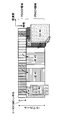
- FIG. 15 is an overall configuration diagram of the radio base station 10 (including the radio base stations 11 and 12) according to the present embodiment.
- the radio base station 10 includes a plurality of transmission / reception antennas 101 for MIMO transmission, an amplifier unit 102, a transmission / reception unit 103, a baseband signal processing unit 104, a call processing unit 105, and a transmission path interface 106. Yes.
- User data transmitted from the radio base station 10 to the user terminal 20 via the downlink is input from the higher station apparatus 30 to the baseband signal processing unit 104 via the transmission path interface 106.
- the baseband signal processing unit 104 performs PDCP layer processing, user data division / combination, RLC layer transmission processing such as RLC (Radio Link Control) retransmission control transmission processing, MAC (Medium Access Control) retransmission control, for example, HARQ transmission processing, scheduling, transmission format selection, channel coding, inverse fast Fourier transform (IFFT) processing, and precoding processing are performed and transferred to each transceiver 103.
- RLC layer transmission processing such as RLC (Radio Link Control) retransmission control transmission processing, MAC (Medium Access Control) retransmission control, for example, HARQ transmission processing, scheduling, transmission format selection, channel coding, inverse fast Fourier transform (IFFT) processing, and precoding processing are performed and transferred to each transceiver 103.
- HARQ transmission processing scheduling, transmission format selection, channel coding, inverse fast Fourier transform (IFFT) processing, and precoding processing are performed and transferred to each transceiver 103.
- IFFT inverse fast Fourier transform
- the baseband signal processing unit 104 notifies the control information for communication in the cell to the user terminal 20 through the broadcast channel.
- the information for communication in the cell includes, for example, the system bandwidth in the uplink or the downlink.
- Each transmission / reception unit 103 converts the baseband signal output by precoding from the baseband signal processing unit 104 for each antenna to a radio frequency band.
- the amplifier unit 102 amplifies the frequency-converted radio frequency signal and transmits the amplified signal using the transmission / reception antenna 101.
- radio frequency signals received by the respective transmission / reception antennas 101 are amplified by the amplifier units 102 and frequency-converted by the respective transmission / reception units 103. It is converted into a baseband signal and input to the baseband signal processing unit 104.
- the baseband signal processing unit 104 performs FFT processing, IDFT processing, error correction decoding, MAC retransmission control reception processing, RLC layer, and PDCP layer reception processing on user data included in the input baseband signal.
- the data is transferred to the higher station apparatus 30 via the transmission path interface 106.
- the call processing unit 105 performs call processing such as communication channel setting and release, status management of the radio base station 10, and radio resource management.
- FIG. 16 is an overall configuration diagram of the user terminal 20 according to the present embodiment.
- the user terminal 20 includes a plurality of transmission / reception antennas 201 for MIMO transmission, an amplifier unit 202, a transmission / reception unit (reception unit) 203, a baseband signal processing unit 204, and an application unit 205.
- radio frequency signals received by a plurality of transmission / reception antennas 201 are each amplified by an amplifier unit 202, converted in frequency by a transmission / reception unit 203, and converted into a baseband signal.
- the baseband signal is subjected to FFT processing, error correction decoding, retransmission control reception processing, and the like by the baseband signal processing unit 204.
- downlink user data is transferred to the application unit 205.
- the application unit 205 performs processing related to layers higher than the physical layer and the MAC layer. Also, broadcast information in the downlink data is also transferred to the application unit 205.
- uplink user data is input from the application unit 205 to the baseband signal processing unit 204.
- transmission processing for retransmission control H-ARQ (Hybrid ARQ)
- channel coding precoding
- DFT processing IFFT processing
- the like are performed and transferred to each transmission / reception unit 203.
- the transmission / reception unit 203 converts the baseband signal output from the baseband signal processing unit 204 into a radio frequency band.
- the amplifier unit 202 amplifies the frequency-converted radio frequency signal and transmits the amplified signal using the transmitting / receiving antenna 201.
- FIG. 17 is a functional configuration diagram of the baseband signal processing unit 104 and some upper layers included in the radio base station 10 according to the present embodiment.
- the functional configuration for downlink (transmission) is mainly shown, but the radio base station 10 may include a functional configuration for uplink (reception).
- the radio base station 10 includes an upper layer control information generation unit 300, a data generation unit 301, a channel encoding unit 302, a modulation unit 303, a mapping unit 304, a downlink control information generation unit 305, common control information.
- the control channel multiplexing unit 309 and the interleaving unit 310 may be omitted.
- the higher layer control information generation unit 300 generates higher layer control information for each user terminal 20.
- the upper layer control information is control information that is upper layer signaling (for example, RRC signaling), and includes, for example, extended PDCCH allocation information.
- the extended PDCCH allocation information indicates, for example, PRB pairs (resource blocks) constituting each extended PDCCH set set in the user terminal 20.
- the data generation unit 301 generates downlink user data for each user terminal 20.
- the downlink user data generated by the data generation unit 301 and the higher layer control information generated by the higher layer control information generation unit 300 are input to the channel coding unit 302 as downlink data transmitted on the PDSCH.
- the channel coding unit 302 performs channel coding on the downlink data for each user terminal 20 according to a coding rate determined based on feedback information from each user terminal 20.
- the modulation unit 303 modulates the channel-coded downlink data according to a modulation scheme determined based on feedback information from each user terminal 20.
- the mapping unit 304 maps the modulated downlink data according to the instruction from the scheduling unit 317.
- the downlink control information generation unit 305 generates UE-specific downlink control information (DCI) for each user terminal 20.
- the UE-specific downlink control information includes PDSCH allocation information (DL grant), PUSCH allocation information (UL grant), and the like.
- the common control information generation unit 306 generates cell-specific common control information.
- the downlink control information generated by the downlink control information generation unit 305 and the common control information generated by the common control information generation unit 306 are input to the channel coding unit 307 as downlink control information transmitted on the PDCCH or the extended PDCCH.
- the channel coding unit 307 performs channel coding on the input downlink control information according to the coding rate instructed from the scheduling unit 317 described later.
- Modulation section 308 modulates channel-coded downlink control information.
- downlink control information transmitted on the PDCCH is input from the modulation unit 308 to the control channel multiplexing unit 309 and multiplexed.
- the downlink control information multiplexed by the control channel multiplexing unit 309 is interleaved by the interleaving unit 310.
- the interleaved downlink control information is input to the IFFT unit 312 together with the measurement reference signal (CSI-RS: Channel State Information-Reference Signal, CRS: Cell specific Reference Signal, etc.) generated by the measurement reference signal generation unit 311. Is done.
- CSI-RS Channel State Information-Reference Signal
- CRS Cell specific Reference Signal, etc.
- the mapping unit 313 maps downlink control information in a predetermined allocation unit (for example, eCCE or eREG) according to an instruction from the scheduling unit 317 described later.
- the mapping unit 313 may map the downlink control information using distributed mapping in accordance with the instruction of the scheduling unit 317, or may map the downlink control information using local mapping (Localized Mapping). .
- the mapped downlink control information includes downlink data transmitted on the PDSCH (that is, downlink data mapped by the mapping unit 304), and a demodulation reference signal (DM-RS) generated by the demodulation reference signal generation unit 314. At the same time, it is input to the weight multiplier 315.
- Weight multiplying section 315 multiplies downlink data transmitted by PDCSH, downlink control information transmitted by enhanced PDCCH, and a demodulation reference signal by a precoding weight specific to user terminal 20, and performs precoding.
- the precoded transmission data is input to the IFFT unit 312 and converted from a frequency domain signal to a time-series signal by inverse fast Fourier transform.
- a cyclic prefix (CP) functioning as a guard interval is inserted by the CP insertion unit 316 into the output signal from the IFFT unit 312 and output to the transmission / reception unit 103.
- CP cyclic prefix
- the scheduling unit 317 is based on instruction information from the higher station apparatus 30 and feedback information from each user terminal 20 (for example, CSI (Channel State Information) including CQI (Channel Quality Indicator), RI (Rank Indicator), etc.)).
- CSI Channel State Information
- CQI Channel Quality Indicator
- RI Rank Indicator
- the scheduling unit 317 configures a plurality of extended PDCCH sets (resource sets) for each user terminal 20. In addition, the scheduling unit 317 determines PRB pairs (resource blocks) constituting each extended PDCCH set. Also, the scheduling unit 317 determines an extended PDCCH set to be used based on the number of user terminals 20 and the like.
- the scheduling unit 317 constitutes a setting unit of the present invention.
- scheduling section 317 assigns each search space candidate so that a plurality of search space candidates of each extended PDCCH set to which local mapping is applied are arranged in different PRB pairs (resource blocks). Determine the ECCE (Extended Control Channel Element) to configure.
- the scheduling unit 317 constitutes a determination unit of the present invention.
- the scheduling unit 317 determines the total number of ECCEs (N ECCE ) in a plurality of PRB pairs constituting each extended PDCCH set to which local mapping is applied, and search space candidates for each aggregation level in each extended PDCCH set. Based on the number (M set (L) ), the ECCE that constitutes each search space candidate may be determined. This ECCE is specified by, for example, an index number represented by the above formula (3).
- scheduling section 317 determines DCI locally from a plurality of PRB pairs constituting an extended PDCCH set based on channel quality information (for example, CQI) fed back from user terminal 20. Select the PRB pair to be mapped.
- the scheduling unit 317 instructs the mapping unit 313 to perform the local mapping of the DCI to the ECCE configuring the search space arranged in the selected PRB pair.
- the scheduling unit 317 constitutes the selection unit of the present invention.
- the scheduling unit 317 may determine ECCEs constituting a plurality of search space candidates of the extended PDCCH set to which distributed mapping is applied using the above equation (1).
- the scheduling unit 317 may determine ECCEs that configure a plurality of search space candidates of the extended PDCCH set to which local mapping is applied using the above equation (4).
- the scheduling unit 317 determines ECCEs constituting a plurality of search space candidates of the extended PDCCH set to which local mapping is applied based on the carrier identifier. May be. More specifically, the scheduling unit 317 may determine using the above equation (5).
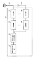
- FIG. 18 is a functional configuration diagram of the baseband signal processing unit 204 included in the user terminal 20.
- the user terminal 20 includes a CP removing unit 401, an FFT unit 402, a demapping unit 403, a deinterleaving unit 404, a PDCCH demodulating unit 405, an extended PDCCH demodulating unit 406, and a PDSCH demodulating unit 407 as functional configurations for downlink (reception).
- the channel estimation unit 408 is provided.
- the cyclic prefix (CP) is removed from the downlink signal received as reception data from the radio base station 10 by the CP removal unit 401.
- the downlink signal from which the CP is removed is input to the FFT unit 402.
- the FFT unit 402 performs fast Fourier transform (FFT) on the downlink signal to convert the signal in the time domain to the signal in the frequency domain, and inputs the signal to the demapping unit 403.
- the demapping unit 403 demaps the downlink signal.
- the downlink control information output from the demapping unit 403 is deinterleaved by the deinterleaving unit 404.
- the PDCCH demodulation unit 405 performs blind decoding, demodulation, channel decoding, and the like of downlink control information (DCI) output from the deinterleaving unit 404 based on a channel estimation result by a channel estimation unit 408 described later. Specifically, PDCCH demodulation section 405 performs blind decoding on a search space candidate notified in advance from radio base station 10 or a predetermined search space candidate, and acquires downlink control information. PDCCH demodulation section 405 outputs PDSCH allocation information included in DCI to PDSCH demodulation section 407.
- DCI downlink control information
- the extended PDCCH demodulation unit 406 performs blind decoding, demodulation, channel decoding, and the like of downlink control information (DCI) output from the demapping unit 403 based on a channel estimation result by a channel estimation unit 408 described later.
- DCI downlink control information
- enhanced PDCCH demodulation section 406 detects PRB pairs constituting each enhanced PDCCH set based on enhanced PDCCH allocation information input from PDSCH demodulation section 407.
- extended PDCCH demodulation section 406 has ECCE (each of which constitutes each of a plurality of search space candidates respectively arranged in different PRB pairs (resource blocks) constituting each extended PDCCH set (resource set). Extended control channel element).
- the enhanced PDCCH demodulation unit 406 performs a total number of ECCEs (N ECCE ) in a plurality of PRB pairs constituting each enhanced PDCCH set to which local mapping is applied, and a search for each aggregation level in each enhanced PDCCH set. Based on the number of space candidates (M set (L) ), ECCEs constituting each search space candidate may be determined. This ECCE is specified by, for example, an index number represented by the above formula (3).
- the extended PDCCH demodulation unit 406 performs blind decoding on the ECCE determined as described above to obtain DCI.
- Extended PDCCH demodulation section 406 outputs PDSCH allocation information included in DCI to PDSCH demodulation section 407.
- Extended PDCCH demodulation section 406 constitutes a determination section and an acquisition section of the present invention.
- the extended PDCCH demodulation unit 406 may determine ECCEs constituting a plurality of search space candidates of the extended PDCCH set to which local mapping is applied using the above equation (4).
- enhanced PDCCH demodulation section 406 determines ECCEs constituting a plurality of search space candidates for the extended PDCCH set of each CC based on the carrier identifier. Also good. More specifically, extended PDCCH demodulation section 406 may determine using equation (5) above.
- the PDSCH demodulation unit 407 performs demodulation, channel decoding, and the like of downlink data output from the demapping unit 403 based on a channel estimation result by a channel estimation unit 408 described later. Specifically, the PDSCH demodulating unit 407 demodulates the PDSCH assigned to the own terminal based on the downlink control information demodulated by the PDCCH demodulating unit 405 or the extended PDCCH demodulating unit 406, and transmits downlink data (downlink) addressed to the own terminal. User data and higher layer control information).
- the channel estimation unit 408 performs channel estimation using a demodulation reference signal (DM-RS), a measurement reference signal (CRS, CSI-RS), and the like.
- Channel estimation section 408 outputs a channel estimation result based on measurement reference signals (CRS, CSI-RS) to PDCCH demodulation section 405.
- channel estimation section 408 outputs the channel estimation result based on the demodulation reference signal (DM-RS) to PDSCH demodulation section 407 and enhanced PDCCH demodulation section 406.
- DM-RS demodulation reference signal
- DM-RS demodulation reference signal
- the radio base station 10 uses, for example, an expression so that a plurality of search space candidates of each extended PDCCH set are arranged in different resource blocks.
- (3) is used to determine the ECCEs that make up each search space candidate. Thereby, a plurality of search space candidates of each extended PDCCH set are arranged in different resource blocks. For this reason, even if the number of extended PDCCH sets set for each user terminal 10 is smaller than the number of search space candidates when no extended PDCCH set is provided, it is possible to obtain a frequency scheduling gain by local mapping of DCI.
- Formula (3) since the different parameter Yk is considered for every sub-frame, a blocking probability can also be reduced.
- Expression (4) is used instead of Expression (3), a plurality of search space candidates of each extended PDCCH set can be arranged in different resource blocks more reliably.
- cross-carrier scheduling is applied to the extended PDCCH by determining the ECCE that constitutes each search space candidate of each CC based on the carrier identifier n CIF of each CC.
- a plurality of search space candidates for each extended PDCCH set can be arranged in different PRB pairs.
Abstract
Priority Applications (4)
| Application Number | Priority Date | Filing Date | Title |
|---|---|---|---|
| RU2015112193/07A RU2584698C1 (ru) | 2012-09-28 | 2013-07-31 | Базовая радиостанция, терминал пользователя, система радиосвязи и способ радиосвязи |
| US14/431,329 US9832764B2 (en) | 2012-09-28 | 2013-07-31 | Radio base station, user terminal, radio communication system and radio communication method |
| EP13840326.6A EP2903371B1 (fr) | 2012-09-28 | 2013-07-31 | Station de base radio, terminal utilisateur, système et procédé de radiocommunication |
| CN201380050754.1A CN104685950B (zh) | 2012-09-28 | 2013-07-31 | 无线基站、用户终端、无线通信系统以及无线通信方法 |
Applications Claiming Priority (6)
| Application Number | Priority Date | Filing Date | Title |
|---|---|---|---|
| JP2012-216731 | 2012-09-28 | ||
| JP2012216731 | 2012-09-28 | ||
| JP2012243093 | 2012-11-02 | ||
| JP2012-243093 | 2012-11-02 | ||
| JP2012-255503 | 2012-11-21 | ||
| JP2012255503A JP5771177B2 (ja) | 2012-09-28 | 2012-11-21 | 無線基地局、ユーザ端末、無線通信システム及び無線通信方法 |
Publications (1)
| Publication Number | Publication Date |
|---|---|
| WO2014050302A1 true WO2014050302A1 (fr) | 2014-04-03 |
Family
ID=50387716
Family Applications (1)
| Application Number | Title | Priority Date | Filing Date |
|---|---|---|---|
| PCT/JP2013/070785 WO2014050302A1 (fr) | 2012-09-28 | 2013-07-31 | Station de base radio, terminal utilisateur, système et procédé de radiocommunication |
Country Status (6)
| Country | Link |
|---|---|
| US (1) | US9832764B2 (fr) |
| EP (1) | EP2903371B1 (fr) |
| JP (1) | JP5771177B2 (fr) |
| CN (1) | CN104685950B (fr) |
| RU (1) | RU2584698C1 (fr) |
| WO (1) | WO2014050302A1 (fr) |
Cited By (2)
| Publication number | Priority date | Publication date | Assignee | Title |
|---|---|---|---|---|
| JP2020505796A (ja) * | 2017-01-20 | 2020-02-20 | オッポ広東移動通信有限公司 | ヌメロロジーと関連付けられるリソースの個別構成 |
| US11974289B2 (en) | 2020-10-13 | 2024-04-30 | Guangdong Oppo Mobile Telecommunicatiosn Corp., Ltd. | Separate configuration of numerology-associated resources |
Families Citing this family (25)
| Publication number | Priority date | Publication date | Assignee | Title |
|---|---|---|---|---|
| WO2013002573A2 (fr) | 2011-06-29 | 2013-01-03 | 엘지전자 주식회사 | Procédé et appareil de transmission d'informations de commande dans un système de communication sans fil |
| JP5781028B2 (ja) * | 2012-07-23 | 2015-09-16 | 株式会社Nttドコモ | 無線通信方法、無線基地局、ユーザ端末及び無線通信システム |
| CN103796309A (zh) * | 2012-10-31 | 2014-05-14 | 华为终端有限公司 | 控制信息的传输方法、基站及用户设备 |
| US9185716B2 (en) | 2013-01-03 | 2015-11-10 | Samsung Electronics Co., Ltd. | Obtaining control channel elements of physical downlink control channels for cross-carrier scheduling |
| US10652768B2 (en) | 2015-04-20 | 2020-05-12 | Qualcomm Incorporated | Control channel based broadcast messaging |
| US10064217B2 (en) * | 2015-10-16 | 2018-08-28 | Samsung Electronics Co., Ltd. | Method and apparatus for enabling flexible numerology in multi-user MIMO system |
| US20190069314A1 (en) * | 2016-01-27 | 2019-02-28 | Ntt Docomo, Inc. | User terminal, radio base station, and radio communication method |
| PT3493623T (pt) * | 2016-07-29 | 2022-06-09 | Ntt Docomo Inc | Terminal de utilizador e método de comunicação sem fios |
| US10606069B2 (en) | 2016-08-01 | 2020-03-31 | Texas Instruments Incorporated | Ultrasound lens structure cleaner architecture and method |
| JP6631929B2 (ja) * | 2016-08-10 | 2020-01-15 | シャープ株式会社 | 通信システム、基地局装置、端末装置、通信方法およびプログラム |
| US20200236697A1 (en) * | 2016-09-21 | 2020-07-23 | Ntt Docomo, Inc. | User terminal and radio communication method |
| WO2018084499A1 (fr) * | 2016-11-03 | 2018-05-11 | 엘지전자 주식회사 | Procédé pour configurer une région de commande de liaison descendante dans un système de communication sans fil et dispositif associé |
| CN108282290B (zh) * | 2017-01-06 | 2022-05-24 | 北京三星通信技术研究有限公司 | 一种通信系统中由终端和基站执行的方法及设备 |
| CN110192418B (zh) * | 2017-01-26 | 2021-09-14 | 华为技术有限公司 | 一种下行链路控制信息的处理方法及装置 |
| US10608779B2 (en) * | 2017-02-06 | 2020-03-31 | Qualcomm Incorporated | Search space configuration for new radio (NR) system |
| US11122552B2 (en) * | 2017-02-06 | 2021-09-14 | Apple Inc. | Downlink control signaling segmentation |
| AU2017418274B2 (en) * | 2017-06-15 | 2022-09-01 | Ntt Docomo, Inc. | User terminal and radio communication method |
| CN111066358B (zh) * | 2017-07-21 | 2023-07-25 | 株式会社Ntt都科摩 | 用户终端以及无线通信方法 |
| WO2019021489A1 (fr) * | 2017-07-28 | 2019-01-31 | 株式会社Nttドコモ | Terminal utilisateur et procédé de communication radio |
| JP2019075609A (ja) * | 2017-10-12 | 2019-05-16 | シャープ株式会社 | 端末装置、基地局装置、および、通信方法 |
| WO2019099435A1 (fr) | 2017-11-14 | 2019-05-23 | Idac Holdings, Inc. | Procédés de détermination de candidats de canal physique de commande de liaison descendante (pdcch) |
| MX2020004965A (es) * | 2017-11-16 | 2020-08-27 | Ntt Docomo Inc | Terminal de usuario y metodo de radiocomunicacion. |
| CN112840612B (zh) * | 2018-08-09 | 2024-03-01 | 株式会社Ntt都科摩 | 终端、无线通信方法、基站以及系统 |
| US10966231B2 (en) * | 2018-09-28 | 2021-03-30 | Qualcomm Incorporated | Configuring aggregation level and physical downlink control channel candidates at a user equipment |
| US20220070909A1 (en) * | 2018-12-11 | 2022-03-03 | Ntt Docomo, Inc. | Terminal and radio communication method |
Citations (1)
| Publication number | Priority date | Publication date | Assignee | Title |
|---|---|---|---|---|
| WO2011023117A1 (fr) * | 2009-08-28 | 2011-03-03 | 华为技术有限公司 | Procédé et appareil de détermination d'un espace de recherche et de ressources de canal de commande candidates |
Family Cites Families (15)
| Publication number | Priority date | Publication date | Assignee | Title |
|---|---|---|---|---|
| WO2008003815A1 (fr) * | 2006-07-07 | 2008-01-10 | Nokia Corporation | Mécanisme d'attribution de ressources radio amélioré |
| KR101468490B1 (ko) * | 2007-05-02 | 2014-12-10 | 삼성전자주식회사 | 무선 통신 시스템에서 제어 채널들의 집합을 한정하여 송수신하는 방법 및 장치 |
| EP2456082B1 (fr) * | 2007-10-29 | 2014-06-11 | Panasonic Corporation | Appareil de station de base de communication sans fil, appareil de station mobile de communication sans fil et procédé d'attribution de canal de contrôle |
| US8238475B2 (en) * | 2007-10-30 | 2012-08-07 | Qualcomm Incorporated | Methods and systems for PDCCH blind decoding in mobile communications |
| EP2403307B1 (fr) * | 2009-02-24 | 2021-05-26 | Sharp Kabushiki Kaisha | Appareils et procédés pour émettre et recevoir des canaux de commande |
| JP5668139B2 (ja) * | 2010-07-26 | 2015-02-12 | エルジー エレクトロニクス インコーポレイティド | マルチキャリアアグリゲーションを支援する無線接続システムにおいて非周期的チャネル状態情報フィードバック方法 |
| WO2012039102A1 (fr) * | 2010-09-21 | 2012-03-29 | パナソニック株式会社 | Station de base, terminal, procédé d'émission et procédé de réception |
| KR101510582B1 (ko) * | 2011-06-15 | 2015-04-08 | 삼성전자주식회사 | 통신 시스템에서 물리 하향링크 제어 시그널링의 확장 |
| US8665811B2 (en) * | 2011-08-15 | 2014-03-04 | Motorola Mobility Llc | Reference signal for a control channel in wireless communication network |
| US9084238B2 (en) * | 2011-09-12 | 2015-07-14 | Blackberry Limited | Searching space and operation for enhanced PDCCH in LTE systems |
| CN102404076B (zh) * | 2011-11-07 | 2014-12-10 | 电信科学技术研究院 | 信息发送及盲检方法和设备 |
| US9054843B2 (en) * | 2012-01-30 | 2015-06-09 | Nokia Solutions And Networks Oy | Search space arrangement for control channel |
| US9198181B2 (en) * | 2012-03-19 | 2015-11-24 | Blackberry Limited | Enhanced common downlink control channels |
| KR102047698B1 (ko) | 2012-04-13 | 2019-12-04 | 엘지전자 주식회사 | 무선 통신 시스템에서 하향링크 제어 채널을 위한 검색 영역을 설정하는 방법 및 이를 위한 장치 |
| US8982693B2 (en) * | 2012-05-14 | 2015-03-17 | Google Technology Holdings LLC | Radio link monitoring in a wireless communication device |
-
2012
- 2012-11-21 JP JP2012255503A patent/JP5771177B2/ja active Active
-
2013
- 2013-07-31 RU RU2015112193/07A patent/RU2584698C1/ru active
- 2013-07-31 US US14/431,329 patent/US9832764B2/en active Active
- 2013-07-31 WO PCT/JP2013/070785 patent/WO2014050302A1/fr active Application Filing
- 2013-07-31 EP EP13840326.6A patent/EP2903371B1/fr active Active
- 2013-07-31 CN CN201380050754.1A patent/CN104685950B/zh active Active
Patent Citations (1)
| Publication number | Priority date | Publication date | Assignee | Title |
|---|---|---|---|---|
| WO2011023117A1 (fr) * | 2009-08-28 | 2011-03-03 | 华为技术有限公司 | Procédé et appareil de détermination d'un espace de recherche et de ressources de canal de commande candidates |
Non-Patent Citations (2)
| Title |
|---|
| "Requirements for Evolved UTRA and Evolved UTRAN", 3GPP TR25.913 |
| See also references of EP2903371A4 |
Cited By (3)
| Publication number | Priority date | Publication date | Assignee | Title |
|---|---|---|---|---|
| JP2020505796A (ja) * | 2017-01-20 | 2020-02-20 | オッポ広東移動通信有限公司 | ヌメロロジーと関連付けられるリソースの個別構成 |
| JP7252121B2 (ja) | 2017-01-20 | 2023-04-04 | オッポ広東移動通信有限公司 | ヌメロロジーと関連付けられるリソースの個別構成 |
| US11974289B2 (en) | 2020-10-13 | 2024-04-30 | Guangdong Oppo Mobile Telecommunicatiosn Corp., Ltd. | Separate configuration of numerology-associated resources |
Also Published As
| Publication number | Publication date |
|---|---|
| US20150282129A1 (en) | 2015-10-01 |
| EP2903371A4 (fr) | 2016-06-22 |
| US9832764B2 (en) | 2017-11-28 |
| RU2584698C1 (ru) | 2016-05-20 |
| CN104685950B (zh) | 2016-12-28 |
| JP2014112752A (ja) | 2014-06-19 |
| EP2903371B1 (fr) | 2018-02-14 |
| CN104685950A (zh) | 2015-06-03 |
| JP5771177B2 (ja) | 2015-08-26 |
| EP2903371A1 (fr) | 2015-08-05 |
Similar Documents
| Publication | Publication Date | Title |
|---|---|---|
| JP5771177B2 (ja) | 無線基地局、ユーザ端末、無線通信システム及び無線通信方法 | |
| JP6219018B2 (ja) | 無線基地局装置、ユーザ端末、無線通信システム及び無線通信方法 | |
| JP5809103B2 (ja) | 無線基地局、ユーザ端末、無線通信システム及び無線通信方法 | |
| JP5726819B2 (ja) | 復号方法、無線基地局、ユーザ端末及び無線通信システム | |
| JP5781028B2 (ja) | 無線通信方法、無線基地局、ユーザ端末及び無線通信システム | |
| JP5829987B2 (ja) | 無線通信方法、無線通信システム及び無線基地局 | |
| JP5554799B2 (ja) | 無線基地局装置、ユーザ端末、無線通信システム及び無線通信方法 | |
| JP6068860B2 (ja) | 無線通信方法、無線基地局、ユーザ端末及び無線通信システム | |
| JP5793131B2 (ja) | 無線基地局、ユーザ端末、無線通信システム及び無線通信方法 | |
| JP6105693B2 (ja) | 無線通信方法、無線通信システム及び無線基地局 | |
| JP6106725B2 (ja) | 無線基地局、ユーザ端末、無線通信システム及び無線通信方法 |
Legal Events
| Date | Code | Title | Description |
|---|---|---|---|
| 121 | Ep: the epo has been informed by wipo that ep was designated in this application |
Ref document number: 13840326 Country of ref document: EP Kind code of ref document: A1 |
|
| WWE | Wipo information: entry into national phase |
Ref document number: 14431329 Country of ref document: US |
|
| NENP | Non-entry into the national phase |
Ref country code: DE |
|
| WWE | Wipo information: entry into national phase |
Ref document number: 2013840326 Country of ref document: EP |
|
| ENP | Entry into the national phase |
Ref document number: 2015112193 Country of ref document: RU Kind code of ref document: A |