図1は、MU-MIMO伝送が適用される無線通信システムの一例を示す図である。図1に示すシステムは、無線基地局(例えば、eNB:eNodeB)のカバレッジエリア内に局所的なカバレッジエリアを有する小型基地局(例えば、RRH:Remote Radio Headなど)が設けられ、階層的に構成されている。このようなシステムにおける下りリンクのMU-MIMO伝送では、無線基地局の複数のアンテナから複数のユーザ端末UE(User Equipment)#1及び#2に対するデータが同時に送信される。また、複数の小型基地局の複数のアンテナから複数のユーザ端末UE#3、#4に対するデータも同時に送信される。
FIG. 1 is a diagram illustrating an example of a wireless communication system to which MU-MIMO transmission is applied. The system shown in FIG. 1 has a hierarchical configuration in which small base stations (for example, RRH: Remote Radio Head, etc.) having a local coverage area are provided within the coverage area of a radio base station (for example, eNB: eNodeB). Has been. In downlink MU-MIMO transmission in such a system, data for a plurality of user terminals UE (User Equipment) # 1 and # 2 are simultaneously transmitted from a plurality of antennas of a radio base station. Further, data for a plurality of user terminals UE # 3 and # 4 are simultaneously transmitted from a plurality of antennas of a plurality of small base stations.
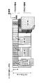
図2は、下りリンクのMU-MIMO伝送が適用される無線フレーム(例えば、1サブフレーム)の一例を示す図である。図2に示すように、MU-MIMO伝送が適用されるシステムでは、各サブフレームにおいて先頭から所定のOFDMシンボル(最大3OFDMシンボル)まで、下り制御チャネル(PDCCH:Physical Downlink Control Channel)用の無線リソース領域(PDCCH領域)として確保される。また、サブフレームの先頭から所定のシンボルより後の無線リソースに、下り共有データチャネル(PDSCH:Physical Downlink Shared Channel)用の無線リソース領域(PDSCH領域)が確保される。
FIG. 2 is a diagram illustrating an example of a radio frame (for example, one subframe) to which downlink MU-MIMO transmission is applied. As shown in FIG. 2, in a system to which MU-MIMO transmission is applied, radio resources for a downlink control channel (PDCCH: Physical Downlink Control Channel) from the beginning to a predetermined OFDM symbol (maximum 3 OFDM symbols) in each subframe. It is secured as a region (PDCCH region). Also, a radio resource area (PDSCH area) for a downlink shared data channel (PDSCH: Physical Downlink Shared Channel) is secured in radio resources after a predetermined symbol from the top of the subframe.
PDCCH領域には、ユーザ端末UE(ここでは、UE#1~#4)に対する下り制御情報(DCI:Downlink Control Information、以下、DCIという)が割当てられる。DCIには、PDSCH領域におけるユーザ端末UEに対するデータの割り当て情報等が含まれる。例えば、図2において、ユーザ端末UE#2は、PDCCH領域に割り当てられたユーザ端末UE#2に対するDCIに基づいて、PDSCH領域に割り当てられたユーザ端末UE#2に対するデータを受信する。
Downlink control information (DCI: Downlink Control Information, hereinafter referred to as DCI) for user terminals UE (here, UE # 1 to # 4) is allocated to the PDCCH region. DCI includes data allocation information for the user terminal UE in the PDSCH region. For example, in FIG. 2, the user terminal UE # 2 receives data for the user terminal UE # 2 assigned to the PDSCH region based on the DCI for the user terminal UE # 2 assigned to the PDCCH region.
また、MU-MIMO伝送においては、同一時間及び同一周波数で複数のユーザ端末UEに対するデータ送信が可能となる。このため、図2のPDSCH領域において、ユーザ端末UE#1に対するデータとユーザ端末UE#5に対するデータを同一の周波数領域に多重することが考えられる。同様に、ユーザ端末UE#4に対するデータとユーザ端末UE#6に対するデータを同一の周波数領域に多重することも考えられる。
In MU-MIMO transmission, data transmission to a plurality of user terminals UE can be performed at the same time and the same frequency. For this reason, in the PDSCH region of FIG. 2, it is conceivable to multiplex data for the user terminal UE # 1 and data for the user terminal UE # 5 in the same frequency region. Similarly, it is also conceivable to multiplex data for user terminal UE # 4 and data for user terminal UE # 6 in the same frequency domain.
しかしながら、図2に示すように、PDSCH領域においてユーザ端末UE#1~#6に対するデータを割り当てようとしても、PDCCH領域において全てのユーザ端末UE#1~#6に対するDCIの割り当て領域を確保できない場合がある。例えば、図2のPDCCH領域では、ユーザ端末UE#5及び#6に対するDCIを割り当てることができない。この場合、DCIを割り当てるPDCCH領域の不足によりPDSCH領域に多重されるユーザ端末UEの数が制限されるため、MU-MIMO伝送による無線リソースの利用効率の向上効果を十分に得られない恐れがある。
However, as shown in FIG. 2, even if data for user terminals UE # 1 to # 6 is to be allocated in the PDSCH area, DCI allocation areas cannot be secured for all user terminals UE # 1 to # 6 in the PDCCH area. There is. For example, in the PDCCH region of FIG. 2, DCI for user terminals UE # 5 and # 6 cannot be assigned. In this case, since the number of user terminals UE multiplexed in the PDSCH region is limited due to the lack of the PDCCH region to which DCI is allocated, there is a possibility that the effect of improving the use efficiency of radio resources by MU-MIMO transmission may not be sufficiently obtained .
このようなPDCCH領域の不足を解決する方法として、サブフレームの先頭から最大3OFDMシンボルの制御領域以外にPDCCHの割当て領域を拡張する(4OFDMシンボル以降の既存のPDSCH領域にPDCCH領域を拡張する)ことが考えられる。PDCCH領域の拡張方法としては、図3Aに示すように、既存のPDSCH領域においてPDSCHとPDCCHとを時分割多重する方法(TDMアプローチ)、図3Bに示すように、既存のPDSCH領域においてPDSCHとPDCCHとを周波数分割多重する方法(FDMアプローチ)が考えられる。
As a method for solving such a shortage of PDCCH regions, the PDCCH allocation region is expanded from the beginning of the subframe to a control region other than a maximum of 3 OFDM symbols (the PDCCH region is expanded to an existing PDSCH region after 4 OFDM symbols). Can be considered. As a method for extending the PDCCH region, as shown in FIG. 3A, a method of time-division multiplexing PDSCH and PDCCH in the existing PDSCH region (TDM approach), as shown in FIG. 3B, PDSCH and PDCCH in the existing PDSCH region. And frequency division multiplexing (FDM approach).
図3Aに示すTDMアプローチでは、サブフレームの4OFDMシンボル以降の一部OFDMシンボルにおいてシステム帯域全体に渡りPDCCHが配置される。一方、図3Bに示すFDMアプローチでは、サブフレームの4OFDMシンボル以降の全OFDMシンボルにおいてシステム帯域の一部にPDCCHが配置される。このFDMアプローチによりPDSCHと周波数分割多重されるPDCCHは、ユーザ固有の参照信号である復調用参照信号(DM-RS:DeModulation-Reference Signal)を用いて復調される。このため、かかるPDCCHで伝送されるDCIは、PDSCHで伝送される下りデータと同様に、ビームフォーミングゲインを得ることができ、PDCCHのキャパシティの増大に有効である。今後は、このFDMアプローチが重要となると考えられる。
In the TDM approach shown in FIG. 3A, PDCCHs are arranged over the entire system band in some OFDM symbols after 4 OFDM symbols in a subframe. On the other hand, in the FDM approach shown in FIG. 3B, PDCCH is arranged in a part of the system band in all OFDM symbols after 4 OFDM symbols in a subframe. The PDCCH frequency-division multiplexed with the PDSCH by this FDM approach is demodulated using a demodulation reference signal (DM-RS: DeModulation-Reference Signal) which is a user-specific reference signal. For this reason, DCI transmitted on the PDCCH can obtain a beamforming gain, similarly to downlink data transmitted on the PDSCH, and is effective for increasing the capacity of the PDCCH. In the future, this FDM approach will be important.
以下、FDMアプローチにおいてPDSCHと周波数分割多重されるPDCCHを拡張PDCCH(enhanced PDCCH)と称する。この拡張PDCCHは、拡張下り制御チャネル(Enhanced Physical Downlink Control CHannel)、ePDCCH、E-PDCCH、FDM型PDCCH、UE-PDCCH等と呼ばれてもよい。
Hereinafter, the PDCCH frequency-division multiplexed with the PDSCH in the FDM approach is referred to as an extended PDCCH (enhanced PDCCH). This extended PDCCH may be called an enhanced downlink control channel (Enhanced Physical Downlink Control CHannel), ePDCCH, E-PDCCH, FDM type PDCCH, UE-PDCCH, or the like.
以上のようなFDMアプローチの拡張PDCCHにおいて、DCIのマッピング方法として、局所マッピング(Localized mapping)と分散マッピング(Distributed Mapping)とが検討されている。図4は、拡張PDCCHにおけるDCIのマッピング方法を説明するための図である。図4Aは、局所マッピングを示し、図4Bは、分散マッピングを示す。
In the extended PDCCH of the FDM approach as described above, as a DCI mapping method, local mapping and distributed mapping are being studied. FIG. 4 is a diagram for explaining a DCI mapping method in the extended PDCCH. FIG. 4A shows local mapping and FIG. 4B shows distributed mapping.
図4A及び4Bに示すように、拡張PDCCHは、システム帯域に分散された所定数の物理リソースブロック(PRB)ペアから構成される。PRBペアは、時間方向に連続する2つのPRBから構成され、周波数方向に付与されるPRBインデックスにより識別される。拡張PDCCHを構成する複数のPRBペアは、上位レイヤによって定められる。当該複数のPRBペアの各々を識別するPRBインデックスは、上位レイヤシグナリングによりユーザ端末UEに通知される。また、拡張PDCCHを構成する複数のPRBペアは、予め仕様で定められる場合もある。
As shown in FIGS. 4A and 4B, the extended PDCCH is composed of a predetermined number of physical resource block (PRB) pairs distributed in the system band. The PRB pair is composed of two PRBs continuous in the time direction, and is identified by a PRB index given in the frequency direction. A plurality of PRB pairs constituting the extended PDCCH are determined by higher layers. The PRB index for identifying each of the plurality of PRB pairs is notified to the user terminal UE by higher layer signaling. In addition, a plurality of PRB pairs constituting the extended PDCCH may be determined in advance by specifications.
図4Aに示すように、局所マッピングでは、1DCIが、拡張PDCCHを構成する特定のPRBペアに局所的にマッピングされる。具体的には、1DCIが、ユーザ端末UEからフィードバックされたチャネル品質情報(例えば、CQI)に基づいて、所定数のPRBペア(例えば、チャネル品質が良い1又は2のPRBペア)内にマッピングされる。これにより、局所マッピングでは、周波数スケジューリングゲインを得ることができる。なお、図4Aにおいて、拡張PDCCHを構成する複数のPRBペアのうち、DCIがマッピングされないPRBペアには、PDSCHがマッピングされてもよい。
As shown in FIG. 4A, in the local mapping, 1DCI is locally mapped to a specific PRB pair constituting the extended PDCCH. Specifically, 1DCI is mapped into a predetermined number of PRB pairs (for example, 1 or 2 PRB pairs with good channel quality) based on channel quality information (for example, CQI) fed back from the user terminal UE. The Thereby, in local mapping, a frequency scheduling gain can be obtained. In FIG. 4A, PDSCH may be mapped to a PRB pair to which DCI is not mapped among a plurality of PRB pairs constituting the extended PDCCH.
図4Bに示すように、分散マッピングでは、1DCIが、拡張PDCCHを構成する複数のPRBペアに分散してマッピングされる。具体的には、1DCIが複数の分割ユニットに分割され、各分割ユニットが上記複数のPRBペア(全てのPRBペアでもよい)に分散してマッピングされる。分散マッピングでは、1DCIをシステム帯域に分散させることにより、周波数ダイバーシチゲインを得ることができる。
As shown in FIG. 4B, in the distributed mapping, 1DCI is distributed and mapped to a plurality of PRB pairs constituting the extended PDCCH. Specifically, 1DCI is divided into a plurality of divided units, and each divided unit is distributed and mapped to the plurality of PRB pairs (may be all PRB pairs). In the dispersion mapping, frequency diversity gain can be obtained by dispersing 1DCI in the system band.
このように、分散マッピングでは、局所マッピングとは異なり、各DCIが複数の分割ユニットに分割され、各分割ユニットが拡張PDCCHを構成する複数のPRBペアに分散してマッピングされる。このため、図5Aに示すように、拡張PDCCHが多くのPRBペア(図5Aでは、8つのPRBペア)から構成される場合、1DCIのみをマッピングしようとすると、無線リソースの利用効率が低下する。1DCIの分割ユニットが多くのPRBペアに分散してマッピングされるので、PDSCHをマッピング可能なPRBペア数が減少するためである。
Thus, in the distributed mapping, unlike the local mapping, each DCI is divided into a plurality of divided units, and each divided unit is distributed and mapped to a plurality of PRB pairs constituting the extended PDCCH. For this reason, as shown in FIG. 5A, when the extended PDCCH is composed of many PRB pairs (eight PRB pairs in FIG. 5A), if only one DCI is mapped, the utilization efficiency of radio resources decreases. This is because 1DCI division units are distributed and mapped to many PRB pairs, and the number of PRB pairs to which PDSCH can be mapped decreases.
そこで、分散マッピングでは、図5Bに示すように、1DCIの分割ユニットが分散してマッピングされるPRBペア数を制限することが検討されている。図5Bでは、1DCIの分割ユニットが分散してマッピングされるPRBペア数が4に制限される。このため、図5Bでは、図5Aに示す場合と比較して、PDSCHをマッピング可能なPRBペア数が増加する。
Therefore, in the distributed mapping, as shown in FIG. 5B, it is considered to limit the number of PRB pairs to which 1DCI divided units are mapped in a distributed manner. In FIG. 5B, the number of PRB pairs to which 1DCI division units are distributed and mapped is limited to four. For this reason, in FIG. 5B, the number of PRB pairs to which the PDSCH can be mapped increases as compared to the case illustrated in FIG. 5A.
また、PDSCHと周波数分割多重される拡張PDCCH(FDMアプローチ)を用いる場合、各ユーザ端末UEに対して複数の拡張PDCCHセットを設定(configure)することも検討されている。図6Aに示すように、各拡張PDCCHセットは、拡張PDCCHに割り当てられる複数のPRBペアを含んで構成される。なお、拡張PDCCHセットは、enhanced PDCCHセット、ePDCCHセット、E-PDCCHセット、単に、セット等と呼ばれてもよい。
Also, when using an extended PDCCH (FDM approach) that is frequency-division multiplexed with the PDSCH, it is also considered to configure a plurality of extended PDCCH sets for each user terminal UE. As shown in FIG. 6A, each extended PDCCH set includes a plurality of PRB pairs assigned to the extended PDCCH. Note that the extended PDCCH set may be called an enhanced PDCCH set, an ePDCCH set, an E-PDCCH set, or simply a set.
図6Aでは、ユーザ端末UE#1-#10のそれぞれに対して、拡張PDCCHセット#1及び#2が重複して設定される。図6Aでは、DCIが伝送されるユーザ端末UEの数が所定数より少ない場合、一方の拡張PDCCHセット#1だけにDCIがマッピングされるので、他方の拡張PDCCH#2をPDSCHのために利用可能となる。このように、各ユーザ端末UEに対して複数の拡張PDCCHセットを重複して設定することで、無線リソースの利用効率を向上させることができる。
In FIG. 6A, extended PDCCH sets # 1 and # 2 are set redundantly for each of user terminals UE # 1- # 10. In FIG. 6A, when the number of user terminals UE to which DCI is transmitted is less than a predetermined number, since DCI is mapped only to one extended PDCCH set # 1, the other extended PDCCH # 2 can be used for PDSCH. It becomes. Thus, the utilization efficiency of a radio | wireless resource can be improved by setting a some extended PDCCH set redundantly with respect to each user terminal UE.
図6Aに示すように、各ユーザ端末UEに対して拡張PDCCHセット#1及び#2が設定される場合、各ユーザ端末UEは、拡張PDCCHセット#1及び#2のサーチスペース候補をブラインド復号する必要がある。かかる場合、図6Bに示すように、拡張PDCCHセット#1及び#2全体でのサーチスペース候補数が拡張PDCCHセットを設けない場合と比較して増加しないように、1拡張PDCCHセット当たりのサーチスペース候補数が設定されてもよい。これにより、各ユーザ端末UEが複数の拡張PDCCHセットをブラインド復号する場合でも、ブラインド復号回数が増加するのを防止できる。
As shown in FIG. 6A, when extended PDCCH sets # 1 and # 2 are set for each user terminal UE, each user terminal UE blind-decodes search space candidates of extended PDCCH sets # 1 and # 2. There is a need. In this case, as shown in FIG. 6B, the search space per extended PDCCH set is set so that the number of search space candidates in the extended PDCCH sets # 1 and # 2 as a whole does not increase as compared with the case where no extended PDCCH set is provided. The number of candidates may be set. Thereby, even when each user terminal UE performs blind decoding of a plurality of enhanced PDCCH sets, it is possible to prevent the number of times of blind decoding from increasing.
以上のように、N(N≧1)個のPRBペアからなる拡張PDCCHセットが定義され、各ユーザ端末UEに対してK(K≧1)個の拡張PDCCHセットが設定される場合、各拡張PDCCHセットにおいて、DCIは、分散マッピングされてもよいし(図4B、図5参照)、局所マッピング(図4A参照)されてもよい。
As described above, when an extended PDCCH set including N (N ≧ 1) PRB pairs is defined and K (K ≧ 1) extended PDCCH sets are set for each user terminal UE, In the PDCCH set, DCI may be distributedly mapped (see FIG. 4B and FIG. 5) or locally mapped (see FIG. 4A).
ところで、拡張PDCCHセットにおいてDCIが局所マッピングされる場合、周波数スケジューリングゲインを得るためには、拡張PDCCHセットの複数のサーチスペース候補が、当該拡張PDCCHセットを構成する異なるPRBペア内に配置されることが望ましい。
By the way, when DCI is locally mapped in the extended PDCCH set, in order to obtain a frequency scheduling gain, a plurality of search space candidates of the extended PDCCH set are arranged in different PRB pairs constituting the extended PDCCH set. Is desirable.
例えば、図6A及び6Bにおいて、拡張PDCCHセット#1のアグリゲーションレベル1の場合、3サーチスペース候補が設けられる。この3サーチスペース候補が、図6Aのそれぞれ異なる3PRBペア#1、#8及び#15に配置される場合、最もチャネル品質の良いPRBペア#15に配置されるサーチスペース候補に対してDCIをマッピングすることで、周波数スケジューリングゲインを得ることができる。
For example, in FIGS. 6A and 6B, in the case of aggregation level 1 of the extended PDCCH set # 1, three search space candidates are provided. When these three search space candidates are arranged in different 3PRB pairs # 1, # 8, and # 15 in FIG. 6A, DCI is mapped to the search space candidates arranged in PRB pair # 15 having the best channel quality. By doing so, a frequency scheduling gain can be obtained.
一方、上述の3サーチスペース候補が、図6Aの同一のPRBペア#1に配置される場合、PRBペア#1のチャネル品質が悪くても当該PRBペア#1に配置されるサーチスペース候補に対してマッピングせざるを得ない。このため、DCIの局所マッピングによる周波数スケジューリングゲインを得ることができない。
On the other hand, when the above-described three search space candidates are arranged in the same PRB pair # 1 in FIG. 6A, even if the channel quality of the PRB pair # 1 is poor, the search space candidates arranged in the PRB pair # 1 Mapping. For this reason, it is not possible to obtain a frequency scheduling gain by DCI local mapping.
また、拡張PDCCHセットにおいてDCIが局所マッピングされる場合、ブロッキング確率を低減するためには、拡張PDCCHセットの各サーチスペース候補が、サブフレーム毎にランダムなECCEで構成されることが望ましい。すなわち、各サーチスペース候補を構成するECCEのインデックス番号が、サブフレーム毎にランダムであることが望ましい。
Also, when DCI is locally mapped in the extended PDCCH set, in order to reduce the blocking probability, each search space candidate in the extended PDCCH set is preferably configured with random ECCE for each subframe. That is, it is desirable that the ECCE index numbers constituting each search space candidate are random for each subframe.
このように、拡張PDCCHセットにおいてDCIが局所マッピングされる場合、周波数スケジューリングゲインを得ることができるように、サーチスペース候補を構成することが望まれている。また、ブロッキング確率を低減できるように、サーチスペース候補を構成することも望まれている。
As described above, when DCI is locally mapped in the extended PDCCH set, it is desired to configure search space candidates so that a frequency scheduling gain can be obtained. It is also desired to configure search space candidates so that the blocking probability can be reduced.
図7及び8は、拡張PDCCHセットにおいてDCIが局所マッピングされる場合のサーチスペースの構成例を説明するための図である。
7 and 8 are diagrams for explaining a configuration example of a search space when DCI is locally mapped in the extended PDCCH set.
図7では、各ユーザ端末UEに対して6個の拡張PDCCHセットが設定され、各拡張PDCCHセットが2個のPRBペアで構成される場合(すなわち、K=6、N=2の場合)が示される。図7に示す場合、拡張PDCCHセットを設けない場合と比較してユーザ端末UEにおけるブラインド復号回数が増加しないように、1拡張PDCCHセット当たりのサーチスペース候補数が設定される。
In FIG. 7, six extended PDCCH sets are set for each user terminal UE, and each extended PDCCH set is configured by two PRB pairs (that is, when K = 6 and N = 2). Indicated. In the case illustrated in FIG. 7, the number of search space candidates per one extended PDCCH set is set so that the number of times of blind decoding in the user terminal UE does not increase compared to the case where no extended PDCCH set is provided.
例えば、アグリゲーションレベル1、2の場合、拡張PDCCHセットを設けない場合のサーチスペース候補数は「6」であるので、拡張PDCCHセット1-6のサーチスペース候補数はそれぞれ「1」である。かかる場合、各拡張PDCCHセットのサーチスペース候補を構成するECCEは、例えば、式(1)に示すハッシュ関数に基づいて決定される。
For example, in the case of aggregation levels 1 and 2, since the number of search space candidates when no extended PDCCH set is provided is “6”, the number of search space candidates for extended PDCCH set 1-6 is “1”, respectively. In such a case, the ECCE constituting the search space candidate of each extended PDCCH set is determined based on, for example, a hash function shown in Expression (1).
式(1)において、NECCEは、拡張PDCCHセット当たりのECCEの総数(図7では、8)である。また、Lは、アグリゲーションレベルである。また、i=0,…,L-1である。なお、m’は、mと等しく、m=0,…,M(L)-1である。また、M(L)は、アグリゲーションレベルLにおけるサーチスペース候補数(図7では、L=1、2の場合、1)である。また、式(1)のYkは、式(2)で定義される。式(2)において、A=39827、D=65537であり、kは、サブフレーム毎に異なるパラメータである。
In Equation (1), N ECCE is the total number of ECCEs per extended PDCCH set (8 in FIG. 7). L is an aggregation level. Further, i = 0,..., L-1. Note that m ′ is equal to m, and m = 0,..., M (L) −1. M (L) is the number of search space candidates at the aggregation level L (in FIG. 7, 1 when L = 1 and 2). Further, Y k in equation (1) is defined by equation (2). In Equation (2), A = 39827 and D = 65537, and k is a parameter that is different for each subframe.
一方、アグリゲーションレベル4、8の場合、拡張PDCCHセットを設けない場合のサーチスペース候補数は「2」である。このため、拡張PDCCHセット1-6の全てにサーチスペース候補を設けることはできない。かかる場合、例えば、C-RNTI(Cell-Radio Network Temporary ID)などに基づいて、ランダムにPRBペアを選択し、選択したPRBペア内のECCEでサーチスペース候補を構成することが考えられる。
On the other hand, in the case of aggregation levels 4 and 8, the number of search space candidates when no extended PDCCH set is provided is “2”. Therefore, search space candidates cannot be provided in all of the extended PDCCH sets 1-6. In such a case, for example, it is conceivable that a PRB pair is randomly selected based on C-RNTI (Cell-Radio Network Temporary ID) or the like, and a search space candidate is configured by ECCE in the selected PRB pair.
図7に示すように、各ユーザ端末UEに対して6個の拡張PDCCHセットが設定される場合(K=6の場合)、拡張PDCCHセット1-6の6個のサーチスペース候補はそれぞれ異なるPRBペアに配置される。このため、チャネル品質の良いPRBペアに配置された拡張PDCCHセットのサーチスペース候補を用いることで、周波数スケジューリングゲインを得ることができる。
As shown in FIG. 7, when six extended PDCCH sets are configured for each user terminal UE (when K = 6), the six search space candidates of the extended PDCCH set 1-6 are different PRBs. Arranged in pairs. For this reason, a frequency scheduling gain can be obtained by using the search space candidate of the extended PDCCH set arranged in the PRB pair with good channel quality.
また、上記式(1)では、サブフレーム毎に異なるパラメータYkが考慮されるので、拡張PDCCHセット1-6のサーチスペース候補を構成するECCEのインデックス番号は異なる。このため、ブロッキング確率を低減することができる。
Also, in the above equation (1), different parameters Y k are taken into account for each subframe, so that the index numbers of ECCEs constituting search space candidates of the extended PDCCH set 1-6 are different. For this reason, a blocking probability can be reduced.
一方で、アグリゲーションレベル1、2と4、8とでは、サーチスペース候補を構成するECCEの決定方法が異なってしまう。また、分散マッピングでは、各ユーザ端末UEに対して2個又は3個の拡張PDCCHセットを設定する場合(K=2又は3の場合)が想定されるため、局所マッピングにおいてもかかる場合をサポートすることが望まれる。
On the other hand, at the aggregation levels 1, 2, 4, and 8, the method of determining the ECCE that constitutes the search space candidate is different. Also, in distributed mapping, it is assumed that 2 or 3 extended PDCCH sets are set for each user terminal UE (in the case of K = 2 or 3), so this case is also supported in local mapping. It is hoped that.
図8では、各ユーザ端末UEに対して2個の拡張PDCCHセットが設定され、各拡張PDCCHセットが6個のPRBペアで構成される場合(すなわち、K=2、N=6の場合)が示される。図8に示す場合も、拡張PDCCHセットを設けない場合と比較してユーザ端末UEにおけるブラインド復号回数が増加しないように、1拡張PDCCHセット当たりのサーチスペース候補数が設定される。
In FIG. 8, two extended PDCCH sets are set for each user terminal UE, and each extended PDCCH set is configured with six PRB pairs (that is, when K = 2 and N = 6). Indicated. Also in the case illustrated in FIG. 8, the number of search space candidates per one extended PDCCH set is set so that the number of times of blind decoding in the user terminal UE does not increase compared to the case where no extended PDCCH set is provided.
例えば、アグリゲーションレベル1の場合、拡張PDCCHセットを設けない場合のサーチスペース候補数は「6」であるので、拡張PDCCHセット1、2のサーチスペース候補数はそれぞれ「3」である。かかる場合、各拡張PDCCHセットのサーチスペース候補を構成するECCEは、例えば、式(1)に示すハッシュ関数に基づいて決定すると、各拡張PDCCHセットの3サーチスペース候補がそれぞれ異なるPRBペアに配置されない場合がある。
For example, in the case of aggregation level 1, since the number of search space candidates when no extended PDCCH set is provided is “6”, the number of search space candidates for extended PDCCH sets 1 and 2 is “3”, respectively. In such a case, if the ECCE configuring the search space candidates of each extended PDCCH set is determined based on, for example, the hash function shown in Equation (1), the three search space candidates of each extended PDCCH set are not arranged in different PRB pairs. There is a case.
具体的には、上記式(1)により、アグリゲーションレベル1において、拡張PDCCHセット1の1番目のサーチスペース候補がECCE#0に決定されるとする。かかる場合、上記式(1)によると、拡張PDCCHセット1の2、3番目のサーチスペース候補がそれぞれECCE#1、#2に決定されることになる。ここで、拡張PDCCHセット1のECCE#0-#3は全てPRBペア#0に含まれる。このため、拡張PDCCHセット1の3サーチスペース候補が全て同一のPRBペア#0に配置されてしまう。
Specifically, it is assumed that the first search space candidate of the extended PDCCH set 1 is determined as ECCE # 0 at the aggregation level 1 by the above formula (1). In such a case, according to the above equation (1), the second and third search space candidates of the extended PDCCH set 1 are determined as ECCE # 1 and # 2, respectively. Here, ECCE # 0- # 3 of extended PDCCH set 1 are all included in PRB pair # 0. For this reason, all three search space candidates of the extended PDCCH set 1 are arranged in the same PRB pair # 0.
同様に、上記式(1)により、アグリゲーションレベル1において、拡張PDCCHセット2の1番目のサーチスペース候補がECCE#7に決定されるとする。かかる場合、上記式(1)によると、拡張PDCCHセット2の2、3番目のサーチスペース候補がそれぞれECCE#8、#9に決定されることになる。ここで、拡張PDCCHセット2のECCE#7はPRBペア#10に含まれ、ECCE#8、#9はPRBペア#27に含まれる。このため、拡張PDCCHセット2の2サーチスペース候補が同一のPRBペア#27に配置されてしまう。
Similarly, it is assumed that the first search space candidate of the extended PDCCH set 2 is determined as ECCE # 7 at the aggregation level 1 by the above formula (1). In this case, according to the above formula (1), the second and third search space candidates of the extended PDCCH set 2 are determined as ECCE # 8 and # 9, respectively. Here, ECCE # 7 of extended PDCCH set 2 is included in PRB pair # 10, and ECCE # 8 and # 9 are included in PRB pair # 27. For this reason, the two search space candidates of the extended PDCCH set 2 are arranged in the same PRB pair # 27.
図8に示すように、各ユーザ端末UEに対して2個の拡張PDCCHセットが設定される場合(K=2の場合)、各拡張PDCCHセットの3個のサーチスペース候補がそれぞれ異なるPRBペアに配置されない場合がある。このように、各ユーザ端末UEに対して設定される拡張PDCCHセット数(K)が拡張PDCCHセットを設けない場合のサーチスペース候補数(例えば、「6」)よりも小さい場合、異なるサーチスペース候補が同一のPRBペアに配置されてしまう確率が高くなる。この結果、DCIの局所マッピングによる周波数スケジューリングゲインを得ることが難しくなるという問題点がある。
As shown in FIG. 8, when two extended PDCCH sets are set for each user terminal UE (when K = 2), three search space candidates of each extended PDCCH set are assigned to different PRB pairs. May not be placed. In this way, when the number of extended PDCCH sets (K) set for each user terminal UE is smaller than the number of search space candidates (for example, “6”) when no extended PDCCH set is provided, different search space candidates. Are likely to be placed in the same PRB pair. As a result, there is a problem that it is difficult to obtain a frequency scheduling gain by DCI local mapping.
そこで、本発明者らは、各ユーザ端末UEに対して設定される拡張PDCCHセット数が拡張PDCCHセットを設けない場合のサーチスペース候補数よりも小さい場合であっても(例えば、K<6の場合)、DCIの局所マッピングによる周波数スケジューリングゲインを得られるサーチスペース候補の構成方法を検討し、本発明に至った。
Therefore, the present inventors have a case where the number of extended PDCCH sets set for each user terminal UE is smaller than the number of search space candidates when no extended PDCCH set is provided (for example, K <6 Case), a search space candidate configuration method capable of obtaining a frequency scheduling gain by local mapping of DCI was studied, and the present invention was achieved.
本発明の第1態様では、無線基地局は、ユーザ端末UEに対して、拡張PDCCHに割り当てられる複数のリソースブロックを含んで各々が構成される複数の拡張PDCCHセット(リソースセット)を設定する。また、無線基地局は、各拡張PDCCHセットの複数のサーチスペース候補がそれぞれ異なるリソースブロックに配置されるように、前記複数のサーチスペース候補を構成する拡張制御チャネル要素を決定する。ユーザ端末UEは、決定した拡張制御チャネル要素をブラインド復号して、ユーザ端末UEに対するDCIを取得する。
In the first aspect of the present invention, the radio base station sets, for the user terminal UE, a plurality of extended PDCCH sets (resource sets) each including a plurality of resource blocks allocated to the extended PDCCH. Further, the radio base station determines the extended control channel elements constituting the plurality of search space candidates so that the plurality of search space candidates of each extended PDCCH set are arranged in different resource blocks. The user terminal UE performs blind decoding on the determined extended control channel element to obtain DCI for the user terminal UE.
これにより、各拡張PDCCHセットの複数のサーチスペース候補がそれぞれ異なるリソースブロックに配置される。このため、各ユーザ端末UEに対して設定される拡張PDCCHセット数が拡張PDCCHセットを設けない場合のサーチスペース候補数より小さくても、DCIの局所マッピングによる周波数スケジューリングゲインを得ることができる。
Thereby, a plurality of search space candidates of each extended PDCCH set are arranged in different resource blocks. For this reason, even if the number of extended PDCCH sets set for each user terminal UE is smaller than the number of search space candidates when no extended PDCCH set is provided, it is possible to obtain a frequency scheduling gain by DCI local mapping.
ここで、リソースブロックは、拡張PDCCHセットを構成する周波数リソース単位であり、例えば、PRBペアやPRBである。以下では、リソースブロックとして、PRBペアを用いる例を説明するが、これに限られない。
Here, the resource block is a frequency resource unit constituting the extended PDCCH set, and is, for example, a PRB pair or a PRB. Hereinafter, an example in which a PRB pair is used as a resource block will be described, but the present invention is not limited to this.
また、リソースブロックは、複数の拡張制御チャネル要素を含んで構成される。拡張制御チャネル要素とは、拡張PDCCHで伝送されるDCIに対するリソース割り当て単位である。拡張制御チャネル要素は、例えば、ECCE、eCCEなどと呼ばれる。以下では、拡張制御チャネル要素をECCEと称し、1リソースブロックが4ECCEで構成されるものとするがこれに限られない。また、1DCIに割り当てられるECCEの統合数(アグリゲーションレベル)は、例えば、1、2、4、8、16であるがこれに限られない。また、ECCEには、拡張PDCCHセット毎にインデックス番号が付与されてもよい。
Also, the resource block includes a plurality of extended control channel elements. The extended control channel element is a resource allocation unit for DCI transmitted on the extended PDCCH. The extended control channel element is called, for example, ECCE or eCCE. In the following, the extended control channel element is referred to as ECCE, and one resource block is configured with 4 ECCEs, but is not limited thereto. Further, the number of ECCE integrations (aggregation levels) allocated to 1 DCI is, for example, 1, 2, 4, 8, 16, but is not limited thereto. In addition, the ECCE may be assigned an index number for each extended PDCCH set.
また、リソースブロックは、複数の拡張リソース要素グループ(eREG)を含んで構成されてもよい。例えば、1リソースブロックは、16eREGで構成され、1eREGは、9RE(リソース要素)で構成されてもよい。また、1ECCEは、4eREGで構成されてもよい。この場合、ECCEは、eREG単位でリソースブロックにマッピングされてもよい。
Further, the resource block may be configured to include a plurality of extended resource element groups (eREGs). For example, one resource block may be configured by 16eREG, and 1eREG may be configured by 9RE (resource element). One ECCE may be composed of 4eREG. In this case, ECCE may be mapped to resource blocks in units of eREG.
また、本発明の第1態様では、無線基地局は、各拡張PDCCHセットを構成するPRBペア内のECCEの総数NECCEと、各拡張PDCCHセットにおけるアグリゲーションレベルL毎のサーチスペース候補数Mset
(L)とに基づいて、各サーチスペース候補を構成するECCEを決定してもよい。
Also, in the first aspect of the present invention, the radio base station performs the total number N ECCE of the ECCEs in the PRB pair constituting each extended PDCCH set and the number of search space candidates M set ( for each aggregation level L in each extended PDCCH set ). LCE) may determine ECCEs that constitute each search space candidate.
具体的には、無線基地局は、式(3)に示すハッシュ関数に基づいて、各サーチスペース候補を構成するECCEを決定する。
Specifically, the radio base station determines an ECCE that constitutes each search space candidate based on the hash function shown in Expression (3).
式(3)において、NECCEは、各拡張PDCCHセットを構成するPRBペア内のECCEの総数、すなわち、拡張PDCCHセット当たりのECCEの総数である。また、Mset
(L)は、アグリゲーションレベル毎のサーチスペース候補数である。Lは、ECCEのアグリゲーションレベルである。m=0,…,Mset
(L)-1であり、i=0,…,L-1であり、Ykは、サブフレーム毎に異なる所定のパラメータである。
In Equation (3), N ECCE is the total number of ECCEs in the PRB pair constituting each extended PDCCH set, that is, the total number of ECCEs per extended PDCCH set. M set (L) is the number of search space candidates for each aggregation level. L is an aggregation level of ECCE. m = 0,..., M set (L) −1, i = 0,..., L−1, and Y k is a predetermined parameter that is different for each subframe.
ここで、図9を参照し、式(3)を用いたサーチスペース候補の構成方法を詳述する。図9は、第1態様に係るサーチスペース候補の構成方法の説明図である。図9では、各ユーザ端末UEに対して2個の拡張PDCCHセットが設定され、各拡張PDCCHセットが6個のPRBペアで構成される場合(すなわち、K=2、N=6の場合)が示される。なお、各拡張DPCCHセットのサーチスペース候補数は、図8と同様に設定される。
Here, with reference to FIG. 9, a configuration method of search space candidates using Expression (3) will be described in detail. FIG. 9 is an explanatory diagram of a search space candidate configuration method according to the first aspect. In FIG. 9, two extended PDCCH sets are set for each user terminal UE, and each extended PDCCH set is configured with six PRB pairs (that is, when K = 2 and N = 6). Indicated. Note that the number of search space candidates for each extended DPCCH set is set in the same manner as in FIG.
また、図9では、拡張PDCCHセット(set)1、2を構成するPRBペアが、周波数方向に連続する2PRBペア単位で交互に配置される。周波数方向に連続する2PRBペア単位で配置することにより、1PRBペアが4ECCEで構成される場合、8ECCEが連結されるアグリゲーションレベル8をサポートできる。また、各拡張PDCCHセットを構成するPRBペアを交互に配置することにより、各拡張PDCCHを周波数方向に分散させることができる。
In FIG. 9, the PRB pairs constituting the extended PDCCH sets (sets) 1 and 2 are alternately arranged in units of 2 PRB pairs continuous in the frequency direction. By arranging 2PRB pairs that are continuous in the frequency direction, when one PRB pair is composed of 4ECCEs, it is possible to support an aggregation level 8 in which 8ECCEs are connected. Further, by alternately arranging the PRB pairs constituting each extended PDCCH set, each extended PDCCH can be dispersed in the frequency direction.
なお、図9に示す配置は、例示にすぎず、これに限られない。例えば、1PRBペアが8ECCEで構成される場合やアグリゲーションレベル8をサポートしない場合、各拡張PDCCHペアを構成するPRBペアは、1PRBペア単位で配置されてもよい。また、拡張PDCCHセットを構成するPRBペアが交互に配置されてなくともよい。
Note that the arrangement shown in FIG. 9 is merely an example and is not limited thereto. For example, when one PRB pair is configured with 8ECCE or when aggregation level 8 is not supported, the PRB pair that configures each extended PDCCH pair may be arranged in units of 1PRB pair. In addition, the PRB pairs constituting the extended PDCCH set may not be alternately arranged.
また、図9では、各PRBペアを構成するECCEには、拡張PDCCHセット毎にインデックス番号が付与される。例えば、拡張PDCCHセット1を構成するPRBペア#0、#1、#18、#19、#36、#37に含まれる全24個のECCEは、周波数方向に通しのインデックス番号#0-#23が付与される。
Further, in FIG. 9, an index number is assigned to each extended PDCCH set to the ECCEs constituting each PRB pair. For example, all 24 ECCEs included in the PRB pairs # 0, # 1, # 18, # 19, # 36, and # 37 constituting the extended PDCCH set 1 are index numbers # 0 to # 23 that are serial numbers in the frequency direction. Is granted.
図9に示す場合、拡張PDCCHセット当たりのECCEの総数NECCEは、「24」である。また、拡張PDCCHセット当たりのサーチスペース候補数Mset
(L)は、アグリゲーションレベルLが1、2の場合「3」であり、アグリゲーションレベルLが4、8の場合「1」である。
In the case illustrated in FIG. 9, the total number N ECCE of ECCE per extended PDCCH set is “24”. Further, the number of search space candidates M set (L) per extended PDCCH set is “3” when the aggregation level L is 1 or 2, and is “1” when the aggregation level L is 4 or 8.
ここで、上記式(3)の所定のパラメータYk=0であるとし、アグリゲーションレベルL=2の場合を考える。かかる場合、上記式(3)によると、拡張PDCCHセット1の1番目のサーチスペース候補(m=0)がECCE#0に決定される。また、2番目のサーチスペース候補(m=1)がECCE#8に決定され、3番目のサーチスペース候補(m=2)がECCE#16に決定される。拡張PDCCHセット1のECCE#0、#8、#16は、それぞれPRBペア#0、#18、#36に含まれる。このため、拡張PDCCHセット1のアグリゲーションレベル2の3サーチスペース候補は、それぞれ異なるPRBペアに配置されることとなる。
Here, it is assumed that the predetermined parameter Y k = 0 in the above equation (3) is assumed and the aggregation level L = 2. In such a case, according to the above equation (3), the first search space candidate (m = 0) of the extended PDCCH set 1 is determined as ECCE # 0. Also, the second search space candidate (m = 1) is determined as ECCE # 8, and the third search space candidate (m = 2) is determined as ECCE # 16. ECCEs # 0, # 8, and # 16 of extended PDCCH set 1 are included in PRB pairs # 0, # 18, and # 36, respectively. For this reason, the 3 search space candidates of aggregation level 2 of the extended PDCCH set 1 are arranged in different PRB pairs.
同様の場合、上記式(3)によると、拡張PDCCHセット2の1、2、3番目のサーチスペース候補(m=0、1、2)がそれぞれECCE#0、#8、#16に決定される。拡張PDCCHセット2のECCE#0、#8、#16は、それぞれPRBペア#9、#27、#45に含まれる。このため、拡張PDCCHセット2のアグリゲーションレベル2の3サーチスペース候補も、それぞれ異なるPRBペアに配置されることとなる。
In the same case, according to the above equation (3), the first, second and third search space candidates (m = 0, 1, 2) of the extended PDCCH set 2 are determined as ECCE # 0, # 8 and # 16, respectively. The ECCEs # 0, # 8, and # 16 of extended PDCCH set 2 are included in PRB pairs # 9, # 27, and # 45, respectively. For this reason, the aggregation search level 2 3 search space candidates of the extended PDCCH set 2 are also arranged in different PRB pairs.
以上のように、上記式(3)によると、拡張PDCCHセット当たりのECCEの総数NECCEと拡張PDCCHセット当たりのサーチスペース候補数Mset
(L)とを考慮して、各サーチスペース候補を構成するECCEが決定される。このため、各ユーザ端末UEに対して設定される拡張PDCCHセット数が小さくても(例えば、図9では、K=2)、各拡張PDCCHセットの複数のサーチスペース候補がそれぞれ異なるPRBペアに配置される。したがって、各拡張PDCCHセットにおいてDCIを局所マッピングする場合に、周波数スケジューリングゲインを得ることができる。
As described above, according to the above equation (3), each search space candidate is configured in consideration of the total number of ECCEs N ECCE per extended PDCCH set and the number of search space candidates M set (L) per extended PDCCH set. The ECCE to be determined is determined. For this reason, even if the number of extended PDCCH sets set for each user terminal UE is small (for example, K = 2 in FIG. 9), a plurality of search space candidates of each extended PDCCH set are arranged in different PRB pairs. Is done. Therefore, a frequency scheduling gain can be obtained when DCI is locally mapped in each extended PDCCH set.
また、上記式(3)によると、サブフレーム毎に異なる所定のパラメータYkを考慮して、各サーチスペース候補を構成するECCEが決定される。このため、各サーチスペース候補を構成するECCEをサブフレーム毎にランダム化させることができ、ブロッキング確率を低減することもできる。
Also, according to the above equation (3), ECCEs that constitute each search space candidate are determined in consideration of a predetermined parameter Yk that differs for each subframe. For this reason, ECCE constituting each search space candidate can be randomized for each subframe, and the blocking probability can be reduced.
なお、上記式(3)は例示にすぎず、これに限られるものではない。拡張PDCCHセット当たりのECCEの総数NECCEと拡張PDCCHセット当たりのサーチスペース候補数Mset
(L)とが考慮されれば、演算方式が変更されてもよく、また、他のパラメータが追加又は削除されてもよい。また、上記式(3)は、図9に示す場合(K=2の場合)に限られず、ユーザ端末UE当たりの拡張PDCCHセット数Kが2以外であっても適用可能である。
In addition, the said Formula (3) is only an illustration and is not restricted to this. If the total number of ECCEs per extended PDCCH set N ECCE and the number of search space candidates M set (L) per extended PDCCH set are taken into consideration, the calculation method may be changed, and other parameters may be added or deleted. May be. Also, the above equation (3) is not limited to the case shown in FIG. 9 (when K = 2), and is applicable even when the number of extended PDCCH sets K per user terminal UE is other than 2.
例えば、無線基地局は、上記式(3)に代えて、式(4)に示すハッシュ関数に基づいて、各サーチスペース候補を構成するECCEを決定してもよい。
式(4)において、NECCEは、各拡張PDCCHセットを構成するPRBペア内のECCEの総数、すなわち、拡張PDCCHセット当たりのECCEの総数である。また、Mset
(L)は、アグリゲーションレベル毎のサーチスペース候補数である。Lは、ECCEのアグリゲーションレベルである。m=0,…,Mset
(L)-1であり、i=0,…,L-1であり、Ykは、サブフレーム毎に異なる所定のパラメータである。
For example, the radio base station may determine the ECCE that constitutes each search space candidate based on the hash function shown in Equation (4) instead of Equation (3).
In Equation (4), N ECCE is the total number of ECCEs in the PRB pair constituting each extended PDCCH set, that is, the total number of ECCEs per extended PDCCH set. M set (L) is the number of search space candidates for each aggregation level. L is an aggregation level of ECCE. m = 0,..., M set (L) −1, i = 0,..., L−1, and Y k is a predetermined parameter that is different for each subframe.
上記式(4)によると、各ユーザ端末UEに対して設定される拡張PDCCHセット数が小さい場合(例えば、図9では、K=2)、より確実に、各拡張PDCCHセットの複数のサーチスペース候補をそれぞれ異なるPRBペアに配置できる。
According to the above equation (4), when the number of extended PDCCH sets set for each user terminal UE is small (for example, K = 2 in FIG. 9), a plurality of search spaces for each extended PDCCH set is more reliably determined. Candidates can be placed in different PRB pairs.
また、無線基地局は、ユーザ端末UEに対してクロスキャリアスケジューリングが適用される場合、キャリア識別子(Carrier Indicator)に基づいて、各コンポーネントキャリアの各サーチスペース候補を構成するECCEを決定してもよい。
In addition, when cross carrier scheduling is applied to the user terminal UE, the radio base station may determine an ECCE constituting each search space candidate for each component carrier based on a carrier identifier (Carrier Indicator). .
ここで、クロスキャリアスケジューリングとは、複数のコンポーネントキャリア(以下、CCという)を統合するキャリアアグリゲーションにおいて、あるCC(例えば、CC#1)の拡張PDCCH又はPDCCHを用いて、当該CC及び他のCC(例えば、CC#1及びCC#2)のPDSCHやPUSCHを割り当てることをいう。拡張PDCCHを用いたクロスキャリアスケジューリングが行なわれる場合、あるCC(例えば、CC#1)の拡張PDCCHを構成するPRBペアに、当該CC及び他のCC(例えば、CC#1及びCC#2)のサーチスペース候補が配置されることとなる。
Here, the cross carrier scheduling is a carrier aggregation that integrates a plurality of component carriers (hereinafter referred to as CC), and uses the extended PDCCH or PDCCH of a certain CC (for example, CC # 1), and the CC and other CCs. (For example, CC # 1 and CC # 2) PDSCH and PUSCH are allocated. When cross-carrier scheduling using the extended PDCCH is performed, the PRB pair that configures the extended PDCCH of a certain CC (for example, CC # 1) has the CC and other CCs (for example, CC # 1 and CC # 2). Search space candidates are arranged.
また、キャリア識別子とは、クロスキャリアスケジューリングが適用される場合に、どのCCのDCIであるかを示す識別子であり、DCIに付加されるCIF(Carrier Indicator Field)に設定される。例えば、最大5CCを統合するキャリアアグリゲーションを想定する場合、CIFは3ビットで構成される。かかる場合、例えば、CIFの設定値「000」~「100」がそれぞれCC#1~CC#5に関連づけられてもよい。なお、CIFのビット数は、キャリアアグリゲーションにおいて統合されるCC数に応じて定められ、3ビットに限られるものではない。また、キャリア識別子は、CI、CC識別子、「Carrier Indicator field value」、「ServCellIndex」などと呼ばれてもよい。
Also, the carrier identifier is an identifier indicating which DCI is CC when cross-carrier scheduling is applied, and is set in a CIF (Carrier Indicator Field) added to DCI. For example, when assuming carrier aggregation integrating a maximum of 5 CCs, the CIF is composed of 3 bits. In this case, for example, CIF setting values “000” to “100” may be associated with CC # 1 to CC # 5, respectively. The number of CIF bits is determined according to the number of CCs integrated in carrier aggregation, and is not limited to 3 bits. The carrier identifier may also be referred to as CI, CC identifier, “Carrier Indicator field value”, “ServCellIndex”, or the like.
具体的には、無線基地局は、ユーザ端末UEに対してクロスキャリアスケジューリングが適用される場合、式(5)に示すハッシュ関数に基づいて、各コンポーネントキャリアの各サーチスペース候補を構成するECCEを決定してもよい。
式(5)において、NECCEは、各拡張PDCCHセットを構成するPRBペア内のECCEの総数、すなわち、拡張PDCCHセット当たりのECCEの総数である。また、Mset
(L)は、アグリゲーションレベル毎のサーチスペース候補数である。Lは、ECCEのアグリゲーションレベルである。m=0,…,Mset
(L)-1であり、i=0,…,L-1であり、Ykは、サブフレーム毎に異なる所定のパラメータである。また、nCIFは、上述のキャリア識別子である。なお、nCIFは、キャリア識別子そのものであってもよいし、当該キャリア識別子に関連付けられる所定のパラメータであってもよい。
Specifically, when cross carrier scheduling is applied to the user terminal UE, the radio base station determines the ECCE that constitutes each search space candidate for each component carrier based on the hash function shown in Equation (5). You may decide.
In Equation (5), N ECCE is the total number of ECCEs in the PRB pair constituting each extended PDCCH set, that is, the total number of ECCEs per extended PDCCH set. M set (L) is the number of search space candidates for each aggregation level. L is an aggregation level of ECCE. m = 0,..., M set (L) −1, i = 0,..., L−1, and Y k is a predetermined parameter that is different for each subframe. N CIF is the above-described carrier identifier. The n CIF may be a carrier identifier itself or a predetermined parameter associated with the carrier identifier.
ここで、上述の図9を参照して、ユーザ端末UEに対してクロスキャリアスケジューリングが適用される場合における、式(5)を用いたサーチスペース候補の構成方法を詳述する。ここでは、一例として、2CC(例えば、CC#1及びCC#2)のキャリアアグリゲーションにおけるクロスキャリアスケジューリングを説明する。また、上記式(5)の所定のパラメータYk=0であり、アグリゲーションレベルL=1であり、CC#1、#2のキャリア識別子nCIFがそれぞれ「0」、「1」であるものとする。
Here, with reference to FIG. 9 described above, a configuration method of search space candidates using Equation (5) when cross carrier scheduling is applied to the user terminal UE will be described in detail. Here, as an example, cross carrier scheduling in 2CC (for example, CC # 1 and CC # 2) carrier aggregation will be described. Further, the predetermined parameter Y k = 0 in the above formula (5), the aggregation level L = 1, and the carrier identifiers n CIF of CC # 1 and CC # 2 are “0” and “1”, respectively. To do.
かかる場合、上記式(5)によると、CC#1の拡張PDCCHセット1の1、2、3番目のサーチスペース候補(m=0、1、2)がそれぞれECCE#0、#8、#16に決定される。また、CC#2のキャリア識別子「1」に基づいて、CC#2の拡張PDCCHセット1の1、2、3番目のサーチスペース候補(m=0、1、2)がそれぞれECCE#1、#9、#17に決定される。これにより、CC#1及びCC#2の拡張PDCCHセット1のアグリゲーションレベル1の3サーチスペース候補は、それぞれ異なるPRBペア#0、#18、#36に配置されることとなる。
In this case, according to the above equation (5), the first, second and third search space candidates (m = 0, 1, 2) of the extended PDCCH set 1 of CC # 1 are ECCE # 0, # 8, # 16, respectively. To be determined. Also, based on the carrier identifier “1” of CC # 2, the first, second and third search space candidates (m = 0, 1, 2) of the extended PDCCH set 1 of CC # 2 are respectively ECCE # 1, ## 9, # 17. As a result, the three search space candidates at aggregation level 1 of the enhanced PDCCH set 1 of CC # 1 and CC # 2 are arranged in different PRB pairs # 0, # 18, and # 36, respectively.
同様の場合、上記式(5)によると、CC#1の拡張PDCCHセット2の1、2、3番目のサーチスペース候補(m=0、1、2)がそれぞれECCE#0、#8、#16に決定される。また、CC#2のキャリア識別子「1」に基づいて、CC#2の拡張PDCCHセット2の1、2、3番目のサーチスペース候補(m=0、1、2)がそれぞれECCE#1、#9、#17に決定される。これにより、CC#1及びCC#2の拡張PDCCHセット1のアグリゲーションレベル1の3サーチスペース候補は、それぞれ異なるPRBペア#9、#27、#45に配置されることとなる。
In the same case, according to the above equation (5), the first, second and third search space candidates (m = 0, 1, 2) of the extended PDCCH set 2 of CC # 1 are respectively ECCE # 0, # 8, # 16 is determined. Also, based on the carrier identifier “1” of CC # 2, the first, second, and third search space candidates (m = 0, 1, 2) of the extended PDCCH set 2 of CC # 2 are respectively ECCE # 1, ## 9, # 17. Accordingly, the three search space candidates at aggregation level 1 of the enhanced PDCCH set 1 of CC # 1 and CC # 2 are arranged in different PRB pairs # 9, # 27, and # 45, respectively.
上記式(5)によると、各CCのキャリア識別子nCIFに基づいて、各CCの各サーチスペース候補を構成するECCEが決定されるので、拡張PDCCHに対してクロスキャリアスケジューリングが適用される場合にも、各拡張PDCCHセットの複数のサーチスペース候補をそれぞれ異なるPRBペアに配置できる。なお、各CCの各サーチスペース候補を構成するECCEを決定する式は、キャリア識別子nCIFが考慮されれば、上記式(5)に限られない。
According to the above equation (5), since the ECCEs constituting each search space candidate of each CC are determined based on the carrier identifier n CIF of each CC, when cross carrier scheduling is applied to the extended PDCCH In addition, a plurality of search space candidates of each extended PDCCH set can be arranged in different PRB pairs. Note that the equation for determining the ECCE that constitutes each search space candidate of each CC is not limited to the above equation (5) as long as the carrier identifier n CIF is considered.
次に、図10-13を参照し、本発明の第2-5態様に係るサーチスペース候補の構成方法を説明する。上述の第1態様では、ユーザ端末UEに設定される拡張PDCCHセットの全てで局所マッピングが適用される。一方、第2-5態様では、一部の拡張PDCCHセットで局所マッピングが適用され、残りの拡張PDCCHセットで分散マッピングが適用される。なお、以下では、上述の第1態様との相違点を中心に説明する。
Next, a search space candidate configuration method according to the second to fifth aspects of the present invention will be described with reference to FIGS. In the first aspect described above, local mapping is applied to all of the extended PDCCH sets set in the user terminal UE. On the other hand, in the second to fifth aspects, local mapping is applied to some extended PDCCH sets, and distributed mapping is applied to the remaining extended PDCCH sets. In the following description, differences from the first aspect will be mainly described.
図10は、第2態様に係るサーチスペース候補の構成方法の説明図である。図10では、各ユーザ端末UEに対して2個の拡張PDCCHセットが設定され、各拡張PDCCHセットが6個のPRBペアで構成される場合が示される。また、図10では、拡張PDCCHセット1で分散マッピングが適用され、拡張PDCCHセット2で局所マッピングが適用される。このように、図10では、分散マッピングが適用される拡張PDCCHセット数(KD)、局所マッピングが適用される拡張PDCCHセット数(KL)が、それぞれ「1」に設定される。
FIG. 10 is an explanatory diagram of a search space candidate configuration method according to the second aspect. FIG. 10 shows a case where two extended PDCCH sets are set for each user terminal UE, and each extended PDCCH set is configured with six PRB pairs. In FIG. 10, distributed mapping is applied in extended PDCCH set 1 and local mapping is applied in extended PDCCH set 2. As described above, in FIG. 10, the number of extended PDCCH sets (KD) to which distributed mapping is applied and the number of extended PDCCH sets (KL) to which local mapping is applied are each set to “1”.
図10でも、各拡張PDCCHセットのサーチスペース候補数は、ユーザ端末UEにおけるブラインド復号回数が増加しないように設定される。ただし、各拡張PDCCHセット間でサーチスペース候補数を均等にする(図9参照)代わりに、図10に示すように、局所/分散マッピングを考慮してサーチスペース候補数が非均等に設定されてもよい。
Also in FIG. 10, the number of search space candidates for each extended PDCCH set is set so that the number of times of blind decoding in the user terminal UE does not increase. However, instead of equalizing the number of search space candidates among the extended PDCCH sets (see FIG. 9), as shown in FIG. 10, the number of search space candidates is set non-uniformly in consideration of local / distributed mapping. Also good.
例えば、図10では、アグリゲーションレベル1、2のサーチスペース候補数は、拡張PDCCH1では「0」に設定される一方、拡張PDCCHセット2では「6」に設定される。拡張PDCCHセット2では局所マッピングが適用されるので、サーチスペース候補数を多くすることで、周波数スケジューリングゲインを得やすくなる。
For example, in FIG. 10, the number of search space candidates at aggregation levels 1 and 2 is set to “0” in the extended PDCCH 1, while it is set to “6” in the extended PDCCH set 2. Since local mapping is applied in the extended PDCCH set 2, it is easy to obtain a frequency scheduling gain by increasing the number of search space candidates.
これに対して、アグリゲーションレベル4、8のサーチスペース候補数は、拡張PDCCH1では「2」に設定される一方、拡張PDCCHセット2では「0」に設定される。アグリゲーションレベルが大きい場合、サーチスペースの候補数が少ないため、局所マッピングにおいて周波数スケジューリングゲインが小さくなることと、大きいアグリゲーションレベルを必要とするようなチャネル品質の悪い環境では、周波数ダイバーシチゲインが得られる分散マッピングの方がより適すると考えられるためである。
On the other hand, the number of search space candidates at aggregation levels 4 and 8 is set to “2” in the extended PDCCH 1, while it is set to “0” in the extended PDCCH set 2. When the aggregation level is large, the number of search space candidates is small, so the frequency scheduling gain is small in local mapping, and in an environment with poor channel quality that requires a large aggregation level, dispersion that can obtain frequency diversity gain This is because mapping is considered more suitable.
また、図10では、拡張PDCCHセット(set)1、2を構成するPRBペアが、周波数方向に1PRBペア単位で交互に配置される。図10では、局所マッピングが適用される拡張PDCCHセット2では、8ECCEが統合されるアグリゲーションレベル8をサポートしていない。このため、1PRBペアが4ECCEで構成される場合、1PRBペア単位で拡張PDCCHセット2を構成するPRBペアを配置できる。
In FIG. 10, the PRB pairs constituting the extended PDCCH sets (sets) 1 and 2 are alternately arranged in units of 1 PRB pair in the frequency direction. In FIG. 10, extended PDCCH set 2 to which local mapping is applied does not support aggregation level 8 in which 8 ECCEs are integrated. For this reason, when one PRB pair is configured by 4ECCE, a PRB pair constituting the extended PDCCH set 2 can be arranged in units of 1PRB pair.
図10に示す場合、各サーチスペース候補を構成するECCEを決定するために、局所マッピングが適用される拡張PDCCHセット2では上記式(3)に示すハッシュ関数を用いることができる。一方、分散マッピングが適用される拡張PDCCHセット1では上記式(1)に示すハッシュ関数を用いることができる。
In the case shown in FIG. 10, in order to determine the ECCE that constitutes each search space candidate, the extended PDCCH set 2 to which local mapping is applied can use the hash function shown in the above equation (3). On the other hand, in the extended PDCCH set 1 to which distributed mapping is applied, the hash function shown in the above equation (1) can be used.
このように、図10では、局所マッピングが適用される拡張PDCCHセット2において、上記式(3)を用いて、各サーチスペース候補を構成するECCEが決定される。このため、局所マッピングが適用される拡張PDCCHセット数が小さくても(例えば、図10では、KL=1)、複数のサーチスペース候補がそれぞれ異なるPRBペアに配置される。したがって、局所マッピングが適用される拡張PDCCHセット2において、周波数スケジューリングゲインを得ることができる。
As described above, in FIG. 10, in the extended PDCCH set 2 to which local mapping is applied, the ECCE that constitutes each search space candidate is determined using the above equation (3). For this reason, even if the number of extended PDCCH sets to which local mapping is applied is small (for example, KL = 1 in FIG. 10), a plurality of search space candidates are arranged in different PRB pairs. Therefore, frequency scheduling gain can be obtained in the enhanced PDCCH set 2 to which local mapping is applied.
図11は、第3態様に係るサーチスペース候補の構成方法の説明図である。図11では、図10と同様に、各ユーザ端末UEに対して2個の拡張PDCCHセットが設定され、拡張PDCCHセット1で分散マッピング適用され、拡張PDCCHセット2で局所マッピングが適用される。また、拡張PDCCHセット1で局所マッピング適用され、拡張PDCCHセット2で分散マッピングが適用されてもよい。
FIG. 11 is an explanatory diagram of a search space candidate configuration method according to the third aspect. In FIG. 11, as in FIG. 10, two extended PDCCH sets are set for each user terminal UE, distributed mapping is applied in extended PDCCH set 1, and local mapping is applied in extended PDCCH set 2. Further, local mapping may be applied in enhanced PDCCH set 1 and distributed mapping may be applied in enhanced PDCCH set 2.
一方、図11では、拡張PDCCHセット(set)1、2が、図10のようにそれぞれ異なるPRBペアで構成されるのではなく、重複するPRBペアで構成される。具体的には、図11では、1PRBペアが、拡張PDCCHセット1用の8eREGと拡張PDCCHセット2用の8eREGとを含んで構成される。この場合、PRBペアに対してeREG単位でECCEがマッピングされる。
On the other hand, in FIG. 11, the extended PDCCH sets (sets) 1 and 2 are not composed of different PRB pairs as in FIG. 10, but are composed of overlapping PRB pairs. Specifically, in FIG. 11, one PRB pair is configured to include 8 eREG for extended PDCCH set 1 and 8 eREG for extended PDCCH set 2. In this case, ECCE is mapped to the PRB pair in units of eREG.
例えば、図11において、PRBペア#0内の8eREG(#2、#3、#6、#7、#10、#11、#14、#15)が、局所マッピングが適用される拡張PDCCHセット2に割り当てられる。このうち、4eREG(#2、#6、#10、#11)により局所マッピング用のECCE#0が構成される。また、4eREG(#3、#7、#11、#15)により局所マッピング用のECCE#1が構成される。
For example, in FIG. 11, 8eREGs (# 2, # 3, # 6, # 7, # 10, # 11, # 14, # 15) in the PRB pair # 0 are extended PDCCH set 2 to which local mapping is applied. Assigned to. Among these, 4eREG (# 2, # 6, # 10, # 11) constitutes ECCE # 0 for local mapping. Moreover, ECCE # 1 for local mapping is comprised by 4eREG (# 3, # 7, # 11, # 15).
図11では、局所マッピングが適用される拡張PDCCHセット2では、1ECCEを構成する4eREGが同一のPRBペア内に含まれるように、4eREGと1ECCEとが対応づけられる。例えば、局所マッピング用のECCE#0(Localized ECCE#0)を構成するeREG#2、#6、#10、#14は全てPRBペア#0に含まれる。
In FIG. 11, in the extended PDCCH set 2 to which local mapping is applied, 4eREG and 1ECCE are associated so that 4eREGs constituting 1ECCE are included in the same PRB pair. For example, eREGs # 2, # 6, # 10, and # 14 constituting ECCE # 0 (Localized ECCE # 0) for local mapping are all included in the PRB pair # 0.
一方、分散マッピングが適用される拡張PDCCHセット1では、1ECCEを構成する4eREGがそれぞれ異なるPRBペア内に含まれるように、4eREGと1ECCEとが対応づけられる。例えば、分散マッピング用のECCE#0(Distributed ECCE#0)を構成するeREG#0、#4、#8、#12は、それぞれ異なるPRBペア#0、#9、#18、#27に含まれる。
On the other hand, in the extended PDCCH set 1 to which distributed mapping is applied, 4eREG and 1ECCE are associated with each other so that 4eREGs constituting 1ECCE are included in different PRB pairs. For example, eREGs # 0, # 4, # 8, and # 12 constituting ECCE # 0 (Distributed ECCE # 0) for distributed mapping are included in different PRB pairs # 0, # 9, # 18, and # 27, respectively. .
図11に示す場合にも、局所マッピングが適用される拡張PDCCHセット2では上記式(3)に示すハッシュ関数を用いて、各サーチスペース候補を構成するECCEを決定できる。なお、分散マッピングが適用される拡張PDCCHセット1では、上記式(1)に示すハッシュ関数を用いることができる。
Also in the case shown in FIG. 11, in the extended PDCCH set 2 to which local mapping is applied, the ECCE that constitutes each search space candidate can be determined using the hash function shown in the above equation (3). In the extended PDCCH set 1 to which distributed mapping is applied, the hash function shown in the above equation (1) can be used.
このように、図11では、局所マッピングが適用される拡張PDCCHセット2において、上記式(3)を用いて、各サーチスペース候補を構成するECCEが決定される。このため、図11に示すように拡張PDCCHセット1、2が構成される場合でも、局所マッピングが適用される拡張PDCCHセット2の各サーチスペース候補がそれぞれ異なるPRBペアに配置される。したがって、局所マッピングが適用される拡張PDCCHセット2において、周波数スケジューリングゲインを得ることができる。
As described above, in FIG. 11, in the extended PDCCH set 2 to which local mapping is applied, the ECCE that constitutes each search space candidate is determined using the above equation (3). Therefore, even when extended PDCCH sets 1 and 2 are configured as shown in FIG. 11, search space candidates of extended PDCCH set 2 to which local mapping is applied are arranged in different PRB pairs. Therefore, frequency scheduling gain can be obtained in the enhanced PDCCH set 2 to which local mapping is applied.
図12は、第4態様に係るサーチスペース候補の構成方法の説明図である。図12でも、各ユーザ端末UEに対して2個の拡張PDCCHセットが設定され、拡張PDCCHセット1で分散マッピング適用され、拡張PDCCHセット2で局所マッピングが適用される。
FIG. 12 is an explanatory diagram of a search space candidate configuration method according to the fourth aspect. Also in FIG. 12, two extended PDCCH sets are set for each user terminal UE, distributed mapping is applied in extended PDCCH set 1, and local mapping is applied in extended PDCCH set 2.
一方、図12では、拡張PDCCHセット(set)1、2を構成するPRB数が同一ではなく、異なるPRB数で構成される。具体的には、図12では、拡張PDCCHセット1は、5PRBペアで構成される。一方、拡張PDCCHセット2は、拡張PDCCHセット1と重複して使用する5PRBペアに、単独で使用する3PRBペアを加えた8PRBペアで構成される。
On the other hand, in FIG. 12, the number of PRBs constituting the extended PDCCH sets (sets) 1 and 2 is not the same, but is composed of different PRB numbers. Specifically, in FIG. 12, the extended PDCCH set 1 is composed of 5 PRB pairs. On the other hand, the extended PDCCH set 2 is configured by 8 PRB pairs obtained by adding 3 PRB pairs to be used independently to 5 PRB pairs to be used overlapping with the extended PDCCH set 1.
また、図12では、拡張PDCCHセット1、2で重複して使用されるPRBペアにおいて、拡張PDCCHセット1、2を構成するeREG数の比率が、図11のように同一ではなく、異なる。具体的には、1PRBペアが、拡張PDCCHセット1用の12eREGと拡張PDCCHセット2用の4eREGとを含んで構成される。この比率は、仕様で決めてもよいし、上位レイヤシグナリングにより通知してもよい。
Also, in FIG. 12, in the PRB pairs used redundantly in the extended PDCCH sets 1 and 2, the ratio of the number of eREGs constituting the extended PDCCH sets 1 and 2 is not the same as shown in FIG. Specifically, one PRB pair includes 12 eREG for extended PDCCH set 1 and 4 eREG for extended PDCCH set 2. This ratio may be determined by specification or may be notified by higher layer signaling.
例えば、図12において、拡張PDCCHセット1、2で重複して使用されるPRBペア#0内の4eREG(#3、#7、#11、#15)が、局所マッピングが適用される拡張PDCCHセット2に割り当てられる。この4eREG(#3、#7、#11、#15)により局所マッピング用のECCE#0が構成される。
For example, in FIG. 12, 4eREGs (# 3, # 7, # 11, # 15) in the PRB pair # 0 used redundantly in the extended PDCCH sets 1 and 2 are extended PDCCH sets to which local mapping is applied. Assigned to 2. The 4eREG (# 3, # 7, # 11, # 15) constitutes ECCE # 0 for local mapping.
また、図12において、拡張PDCCHセット2単独で使用されるPRBペア#45では、16eREG(#0-#15)により局所マッピング用の4ECCE#5-8が構成される。具体的には、PRBペア#45のECCE#5は、4eREG(#0、#4、#8、#12)で構成される。このように、図12において、1PRBペア内の1ECCEは、連続する4eREGではなく、分散された4eREGで構成されてもよい。
Also, in FIG. 12, in the PRB pair # 45 used by the extended PDCCH set 2 alone, 4ECCE # 5-8 for local mapping is configured by 16eREG (# 0- # 15). Specifically, ECCE # 5 of PRB pair # 45 is composed of 4eREGs (# 0, # 4, # 8, # 12). As described above, in FIG. 12, one ECCE in one PRB pair may be composed of distributed 4eREGs instead of consecutive 4eREGs.
図12に示す場合にも、局所マッピングが適用される拡張PDCCHセット2において、上記式(3)に示すハッシュ関数を用いて、各サーチスペース候補を構成するECCEを決定できる。これにより、図12に示すように拡張PDCCHセット1、2が構成される場合でも、局所マッピングが適用される拡張PDCCHセット2の各サーチスペース候補がそれぞれ異なるPRBペアに配置される。したがって、局所マッピングが適用される拡張PDCCHセット2において、周波数スケジューリングゲインを得ることができる。
Also in the case shown in FIG. 12, in the extended PDCCH set 2 to which local mapping is applied, the ECCE that constitutes each search space candidate can be determined using the hash function shown in the above equation (3). Thereby, even when the extended PDCCH sets 1 and 2 are configured as shown in FIG. 12, the search space candidates of the extended PDCCH set 2 to which local mapping is applied are arranged in different PRB pairs. Therefore, frequency scheduling gain can be obtained in the enhanced PDCCH set 2 to which local mapping is applied.
図13は、第5態様に係るサーチスペース候補の構成方法の説明図である。図13でも、各ユーザ端末UEに対して2個の拡張PDCCHセットが設定され、拡張PDCCHセット1で分散マッピング適用され、拡張PDCCHセット2で局所マッピングが適用される。
FIG. 13 is an explanatory diagram of a search space candidate configuration method according to the fifth aspect. Also in FIG. 13, two extended PDCCH sets are set for each user terminal UE, distributed mapping is applied in extended PDCCH set 1, and local mapping is applied in extended PDCCH set 2.
上記図11及び12では、拡張PDCCHセット1、2が、少なくとも一部が重複するPRBペアで構成される場合に、PRBペアに対してeREG単位でECCEがマッピングされる。しかしながら、上述のeREG単位でのマッピングは、図13に示すように、拡張PDCCHセット(set)1、2がそれぞれ異なるPRBペアで構成される場合に適用されてもよい。
11 and 12, when the extended PDCCH sets 1 and 2 are configured by PRB pairs at least partially overlapping, ECCE is mapped to the PRB pair in units of eREG. However, the mapping in units of eREG described above may be applied when the extended PDCCH sets (sets) 1 and 2 are configured with different PRB pairs as shown in FIG.
以上、図9-13に示す拡張PDCCHセット1、2の構成は例示にすぎず、これに限られない。例えば、1PRBペアあたりのeREG数と1ECCEあたりのeREG数は、図11-13に示すものに限られない。また、図9-13に示す構成を2以上の拡張PDCCHセット数の場合にも適用可能であることはもちろんである。
As described above, the configurations of the extended PDCCH sets 1 and 2 shown in FIG. 9-13 are merely examples, and are not limited thereto. For example, the number of eREGs per 1 PRB pair and the number of eREGs per 1 ECCE are not limited to those shown in FIG. 11-13. Of course, the configuration shown in FIG. 9-13 can also be applied to the case of two or more extended PDCCH sets.
また、図10-13を参照して説明した第2-第5態様に係るサーチスペース候補の構成方法では、局所マッピングが適用される拡張PDCCHセットにおいて、各サーチスペース候補を構成するECCEが、上記式(4)を用いて決定されてもよい。
Also, in the search space candidate configuration method according to the second to fifth aspects described with reference to FIGS. 10-13, in the extended PDCCH set to which local mapping is applied, the ECCEs that configure each search space candidate are It may be determined using equation (4).
また、図10-13を参照して説明した第2-第5態様に係るサーチスペース候補の構成方法では、ユーザ端末UEに対してクロスキャリアスケジューリングが適用される場合には、局所マッピングが適用される拡張PDCCHセットにおいて、各CCの各サーチスペース候補を構成するECCEが、キャリア識別子に基づいて決定されてもよい。より具体的には、上記式(5)を用いて、各CCの各サーチスペース候補を構成するECCEが決定されてもよい。
Also, in the search space candidate configuration method according to the second to fifth aspects described with reference to FIGS. 10-13, when cross carrier scheduling is applied to the user terminal UE, local mapping is applied. In the extended PDCCH set, ECCEs constituting each search space candidate of each CC may be determined based on the carrier identifier. More specifically, ECCE that constitutes each search space candidate of each CC may be determined using the above equation (5).
以下、本実施の形態に係る無線通信システムについて、詳細に説明する。この無線通信システムでは、上述の第1-5態様に係るサーチスペース候補の構成方法が適用される。
Hereinafter, the radio communication system according to the present embodiment will be described in detail. In this radio communication system, the search space candidate configuration method according to the first to fifth aspects described above is applied.
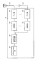
(無線通信システムの構成)
図14は、本実施の形態に係る無線通信システムの概略構成図である。なお、図14に示す無線通信システムは、例えば、LTEシステム或いは、SUPER 3Gが包含されるシステムである。この無線通信システムでは、LTEシステムのシステム帯域を1単位とする複数の基本周波数ブロック(コンポーネントキャリア)を一体としたキャリアアグリゲーションが適用される。また、この無線通信システムは、IMT-Advancedと呼ばれても良いし、4G、FRA(Future Radio Access)と呼ばれても良い。
(Configuration of wireless communication system)
FIG. 14 is a schematic configuration diagram of a radio communication system according to the present embodiment. Note that the radio communication system illustrated in FIG. 14 is a system including, for example, an LTE system or SUPER 3G. In this wireless communication system, carrier aggregation in which a plurality of basic frequency blocks (component carriers) with the system band of the LTE system as one unit is integrated is applied. Further, this radio communication system may be called IMT-Advanced, or may be called 4G, FRA (Future Radio Access).
図14に示すように、無線通信システム1は、マクロセルC1を形成する無線基地局11と、マクロセルC1内に配置され、マクロセルC1よりも狭いスモールセルC2を形成する無線基地局12a及び12bとを備えている。また、マクロセルC1及び各スモールセルC2には、ユーザ端末20が配置されている。ユーザ端末20は、無線基地局11及び無線基地局12の双方と無線通信可能に構成されている。
As shown in FIG. 14, the radio communication system 1 includes a radio base station 11 that forms a macro cell C1, and radio base stations 12a and 12b that are arranged in the macro cell C1 and form a small cell C2 that is narrower than the macro cell C1. I have. Moreover, the user terminal 20 is arrange | positioned at the macrocell C1 and each small cell C2. The user terminal 20 is configured to be capable of wireless communication with both the wireless base station 11 and the wireless base station 12.
ユーザ端末20と無線基地局11との間は、相対的に低い周波数帯域(例えば、2GHz)で帯域幅が広いキャリア(既存キャリア、Legacy carrierなどと呼ばれる)を用いて通信が行なわれる。一方、ユーザ端末20と無線基地局12との間は、相対的に高い周波数帯域(例えば、3.5GHzなど)で帯域幅狭いキャリアが用いられてもよいし、無線基地局11との間と同じキャリアが用いられてもよい。無線基地局11及び各無線基地局12は、有線接続又は無線接続されている。
Communication between the user terminal 20 and the radio base station 11 is performed using a carrier having a relatively low frequency band (for example, 2 GHz) and a wide bandwidth (referred to as an existing carrier or a legacy carrier). On the other hand, between the user terminal 20 and the radio base station 12, a carrier with a narrow bandwidth in a relatively high frequency band (for example, 3.5 GHz) may be used. The same carrier may be used. The wireless base station 11 and each wireless base station 12 are wired or wirelessly connected.
無線基地局11及び各無線基地局12は、それぞれ上位局装置30に接続され、上位局装置30を介してコアネットワーク40に接続される。なお、上位局装置30には、例えば、アクセスゲートウェイ装置、無線ネットワークコントローラ(RNC)、モビリティマネジメントエンティティ(MME)等が含まれるが、これに限定されるものではない。また、各無線基地局12は、無線基地局11を介して上位局装置に接続されてもよい。
The radio base station 11 and each radio base station 12 are connected to the higher station apparatus 30 and connected to the core network 40 via the higher station apparatus 30. The upper station device 30 includes, for example, an access gateway device, a radio network controller (RNC), a mobility management entity (MME), and the like, but is not limited thereto. Further, each radio base station 12 may be connected to a higher station apparatus via the radio base station 11.
なお、無線基地局11は、相対的に広いカバレッジを有する無線基地局であり、eNodeB、無線基地局装置、送信ポイントなどと呼ばれてもよい。また、無線基地局12は、局所的なカバレッジを有する無線基地局であり、ピコ基地局、フェムト基地局、Home eNodeB、RRH(Remote Radio Head)、マイクロ基地局、送信ポイントなどと呼ばれてもよい。以下、無線基地局11及び12を区別しない場合は、無線基地局10と総称する。各ユーザ端末20は、LTE、LTE-Aなどの各種通信方式に対応した端末であり、移動通信端末だけでなく固定通信端末を含んでよい。
Note that the radio base station 11 is a radio base station having a relatively wide coverage, and may be called an eNodeB, a radio base station apparatus, a transmission point, or the like. The radio base station 12 is a radio base station having local coverage, and may be called a pico base station, a femto base station, a Home eNodeB, an RRH (Remote Radio Head), a micro base station, a transmission point, or the like. Good. Hereinafter, when the radio base stations 11 and 12 are not distinguished, they are collectively referred to as a radio base station 10. Each user terminal 20 is a terminal that supports various communication schemes such as LTE and LTE-A, and may include not only a mobile communication terminal but also a fixed communication terminal.
無線通信システムにおいては、無線アクセス方式として、下りリンクについてはOFDMA(直交周波数分割多元接続)が適用され、上りリンクについてはSC-FDMA(シングルキャリア-周波数分割多元接続)が適用される。OFDMAは、周波数帯域を複数の狭い周波数帯域(サブキャリア)に分割し、各サブキャリアにデータをマッピングして通信を行うマルチキャリア伝送方式である。SC-FDMAは、システム帯域を端末毎に1つ又は連続したリソースブロックからなる帯域に分割し、複数の端末が互いに異なる帯域を用いることで、端末間の干渉を低減するシングルキャリア伝送方式である。
In a wireless communication system, OFDMA (Orthogonal Frequency Division Multiple Access) is applied to the downlink and SC-FDMA (Single Carrier Frequency Division Multiple Access) is applied to the uplink as the radio access scheme. OFDMA is a multi-carrier transmission scheme that performs communication by dividing a frequency band into a plurality of narrow frequency bands (subcarriers) and mapping data to each subcarrier. SC-FDMA is a single carrier transmission method that reduces interference between terminals by dividing a system band into bands each consisting of one or continuous resource blocks for each terminal, and a plurality of terminals using different bands. .
ここで、図14に示す無線通信システムで用いられる通信チャネルについて説明する。下りリンクの通信チャネルは、各ユーザ端末20で共有されるPDSCH(Physical Downlink Shared Channel)と、下りL1/L2制御チャネル(PDCCH、PCFICH、PHICH、拡張PDCCH)とを有する。PDSCHにより、ユーザデータ及び上位制御情報が伝送される。PDCCH(Physical Downlink Control Channel)により、PDSCHおよびPUSCHのスケジューリング情報等が伝送される。PCFICH(Physical Control Format Indicator Channel)により、PDCCHに用いるOFDMシンボル数が伝送される。PHICH(Physical Hybrid-ARQ Indicator Channel)により、PUSCHに対するHARQのACK/NACKが伝送される。また、拡張PDCCH(Enhanced Physical Downlink Control Channel、ePDCCH、E-PDCCH、FDM型PDCCH等とも呼ばれる)により、PDSCH及びPUSCHのスケジューリング情報等が伝送されてもよい。この拡張PDCCH(拡張下り制御チャネル)は、PDSCH(下り共有データチャネル)と周波数分割多重され、PDCCHの容量不足を補うために使用される。
Here, communication channels used in the wireless communication system shown in FIG. 14 will be described. The downlink communication channel includes a PDSCH (Physical Downlink Shared Channel) shared by each user terminal 20 and a downlink L1 / L2 control channel (PDCCH, PCFICH, PHICH, extended PDCCH). User data and higher control information are transmitted by the PDSCH. PDSCH and PUSCH scheduling information and the like are transmitted by PDCCH (Physical Downlink Control Channel). The number of OFDM symbols used for PDCCH is transmitted by PCFICH (Physical Control Format Indicator Channel). The HARQ ACK / NACK for PUSCH is transmitted by PHICH (Physical Hybrid-ARQ Indicator Channel). In addition, PDSCH and PUSCH scheduling information and the like may be transmitted by an extended PDCCH (also called Enhanced Physical Downlink Control Channel, ePDCCH, E-PDCCH, FDM type PDCCH, etc.). This enhanced PDCCH (enhanced downlink control channel) is frequency-division multiplexed with PDSCH (downlink shared data channel), and is used to compensate for the lack of PDCCH capacity.
上りリンクの通信チャネルは、各ユーザ端末20で共有される上りデータチャネルとしてのPUSCH(Physical Uplink Shared Channel)と、上りリンクの制御チャネルであるPUCCH(Physical Uplink Control Channel)とを有する。このPUSCHにより、ユーザデータや上位制御情報が伝送される。また、PUCCHにより、下りリンクの無線品質情報(CQI:Channel Quality Indicator)、ACK/NACK等が伝送される。
The uplink communication channel includes a PUSCH (Physical Uplink Shared Channel) as an uplink data channel shared by each user terminal 20 and a PUCCH (Physical Uplink Control Channel) as an uplink control channel. User data and higher control information are transmitted by this PUSCH. Also, downlink radio quality information (CQI: Channel Quality Indicator), ACK / NACK, and the like are transmitted by PUCCH.
図15は、本実施の形態に係る無線基地局10(無線基地局11及び12を含む)の全体構成図である。無線基地局10は、MIMO伝送のための複数の送受信アンテナ101と、アンプ部102と、送受信部103と、ベースバンド信号処理部104と、呼処理部105と、伝送路インターフェース106とを備えている。
FIG. 15 is an overall configuration diagram of the radio base station 10 (including the radio base stations 11 and 12) according to the present embodiment. The radio base station 10 includes a plurality of transmission / reception antennas 101 for MIMO transmission, an amplifier unit 102, a transmission / reception unit 103, a baseband signal processing unit 104, a call processing unit 105, and a transmission path interface 106. Yes.
下りリンクにより無線基地局10からユーザ端末20に送信されるユーザデータは、上位局装置30から伝送路インターフェース106を介してベースバンド信号処理部104に入力される。
User data transmitted from the radio base station 10 to the user terminal 20 via the downlink is input from the higher station apparatus 30 to the baseband signal processing unit 104 via the transmission path interface 106.
ベースバンド信号処理部104では、PDCPレイヤの処理、ユーザデータの分割・結合、RLC(Radio Link Control)再送制御の送信処理などのRLCレイヤの送信処理、MAC(Medium Access Control)再送制御、例えば、HARQの送信処理、スケジューリング、伝送フォーマット選択、チャネル符号化、逆高速フーリエ変換(IFFT:Inverse Fast Fourier Transform)処理、プリコーディング処理が行われて各送受信部103に転送される。また、下りリンクの制御チャネルの信号に関しても、チャネル符号化や逆高速フーリエ変換等の送信処理が行われて、各送受信部103に転送される。
The baseband signal processing unit 104 performs PDCP layer processing, user data division / combination, RLC layer transmission processing such as RLC (Radio Link Control) retransmission control transmission processing, MAC (Medium Access Control) retransmission control, for example, HARQ transmission processing, scheduling, transmission format selection, channel coding, inverse fast Fourier transform (IFFT) processing, and precoding processing are performed and transferred to each transceiver 103. The downlink control channel signal is also subjected to transmission processing such as channel coding and inverse fast Fourier transform, and is transferred to each transceiver 103.
また、ベースバンド信号処理部104は、報知チャネルにより、ユーザ端末20に対して、当該セルにおける通信のための制御情報を通知する。当該セルにおける通信のための情報には、例えば、上りリンク又は下りリンクにおけるシステム帯域幅などが含まれる。
Also, the baseband signal processing unit 104 notifies the control information for communication in the cell to the user terminal 20 through the broadcast channel. The information for communication in the cell includes, for example, the system bandwidth in the uplink or the downlink.
各送受信部103は、ベースバンド信号処理部104からアンテナ毎にプリコーディングして出力されたベースバンド信号を無線周波数帯に変換する。アンプ部102は、周波数変換された無線周波数信号を増幅して送受信アンテナ101により送信する。
Each transmission / reception unit 103 converts the baseband signal output by precoding from the baseband signal processing unit 104 for each antenna to a radio frequency band. The amplifier unit 102 amplifies the frequency-converted radio frequency signal and transmits the amplified signal using the transmission / reception antenna 101.
一方、上りリンクによりユーザ端末20から無線基地局10に送信されるデータについては、各送受信アンテナ101で受信された無線周波数信号がそれぞれアンプ部102で増幅され、各送受信部103で周波数変換されてベースバンド信号に変換され、ベースバンド信号処理部104に入力される。
On the other hand, for data transmitted from the user terminal 20 to the radio base station 10 via the uplink, radio frequency signals received by the respective transmission / reception antennas 101 are amplified by the amplifier units 102 and frequency-converted by the respective transmission / reception units 103. It is converted into a baseband signal and input to the baseband signal processing unit 104.
ベースバンド信号処理部104では、入力されたベースバンド信号に含まれるユーザデータに対して、FFT処理、IDFT処理、誤り訂正復号、MAC再送制御の受信処理、RLCレイヤ、PDCPレイヤの受信処理がなされ、伝送路インターフェース106を介して上位局装置30に転送される。呼処理部105は、通信チャネルの設定や解放等の呼処理や、無線基地局10の状態管理や、無線リソースの管理を行う。
The baseband signal processing unit 104 performs FFT processing, IDFT processing, error correction decoding, MAC retransmission control reception processing, RLC layer, and PDCP layer reception processing on user data included in the input baseband signal. The data is transferred to the higher station apparatus 30 via the transmission path interface 106. The call processing unit 105 performs call processing such as communication channel setting and release, status management of the radio base station 10, and radio resource management.
図16は、本実施の形態に係るユーザ端末20の全体構成図である。ユーザ端末20は、MIMO伝送のための複数の送受信アンテナ201と、アンプ部202と、送受信部(受信部)203と、ベースバンド信号処理部204と、アプリケーション部205とを備えている。
FIG. 16 is an overall configuration diagram of the user terminal 20 according to the present embodiment. The user terminal 20 includes a plurality of transmission / reception antennas 201 for MIMO transmission, an amplifier unit 202, a transmission / reception unit (reception unit) 203, a baseband signal processing unit 204, and an application unit 205.
下りリンクのデータについては、複数の送受信アンテナ201で受信された無線周波数信号がそれぞれアンプ部202で増幅され、送受信部203で周波数変換されてベースバンド信号に変換される。このベースバンド信号は、ベースバンド信号処理部204でFFT処理や、誤り訂正復号、再送制御の受信処理等がなされる。この下りリンクのデータの内、下りリンクのユーザデータは、アプリケーション部205に転送される。アプリケーション部205は、物理レイヤやMACレイヤより上位のレイヤに関する処理等を行う。また、下りリンクのデータの内、報知情報もアプリケーション部205に転送される。
For downlink data, radio frequency signals received by a plurality of transmission / reception antennas 201 are each amplified by an amplifier unit 202, converted in frequency by a transmission / reception unit 203, and converted into a baseband signal. The baseband signal is subjected to FFT processing, error correction decoding, retransmission control reception processing, and the like by the baseband signal processing unit 204. Among the downlink data, downlink user data is transferred to the application unit 205. The application unit 205 performs processing related to layers higher than the physical layer and the MAC layer. Also, broadcast information in the downlink data is also transferred to the application unit 205.
一方、上りリンクのユーザデータについては、アプリケーション部205からベースバンド信号処理部204に入力される。ベースバンド信号処理部204では、再送制御(H-ARQ (Hybrid ARQ))の送信処理や、チャネル符号化、プリコーディング、DFT処理、IFFT処理等が行われて各送受信部203に転送される。送受信部203は、ベースバンド信号処理部204から出力されたベースバンド信号を無線周波数帯に変換する。その後、アンプ部202は、周波数変換された無線周波数信号を増幅して送受信アンテナ201により送信する。
On the other hand, uplink user data is input from the application unit 205 to the baseband signal processing unit 204. In the baseband signal processing unit 204, transmission processing for retransmission control (H-ARQ (Hybrid ARQ)), channel coding, precoding, DFT processing, IFFT processing, and the like are performed and transferred to each transmission / reception unit 203. The transmission / reception unit 203 converts the baseband signal output from the baseband signal processing unit 204 into a radio frequency band. Thereafter, the amplifier unit 202 amplifies the frequency-converted radio frequency signal and transmits the amplified signal using the transmitting / receiving antenna 201.
図17は、本実施の形態に係る無線基地局10が有するベースバンド信号処理部104及び一部の上位レイヤの機能構成図である。なお、図17においては、下りリンク(送信)用の機能構成を主に示しているが、無線基地局10は、上りリンク(受信)用の機能構成を備えてもよい。
FIG. 17 is a functional configuration diagram of the baseband signal processing unit 104 and some upper layers included in the radio base station 10 according to the present embodiment. In FIG. 17, the functional configuration for downlink (transmission) is mainly shown, but the radio base station 10 may include a functional configuration for uplink (reception).
図17に示すように、無線基地局10は、上位レイヤ制御情報生成部300、データ生成部301、チャネル符号化部302、変調部303、マッピング部304、下り制御情報生成部305、共通制御情報生成部306、チャネル符号化部307、変調部308、制御チャネル多重部309、インタリーブ部310、測定用参照信号生成部311、IFFT部312、マッピング部313、復調用参照信号生成部314、ウェイト乗算部315、CP挿入部316、スケジューリング部317を具備する。なお、無線基地局10が、スモールセルC2を形成する無線基地局12である場合、制御チャネル多重部309、インタリーブ部310は省略されてもよい。
As illustrated in FIG. 17, the radio base station 10 includes an upper layer control information generation unit 300, a data generation unit 301, a channel encoding unit 302, a modulation unit 303, a mapping unit 304, a downlink control information generation unit 305, common control information. Generation unit 306, channel coding unit 307, modulation unit 308, control channel multiplexing unit 309, interleaving unit 310, measurement reference signal generation unit 311, IFFT unit 312, mapping unit 313, demodulation reference signal generation unit 314, weight multiplication Unit 315, CP insertion unit 316, and scheduling unit 317. Note that when the radio base station 10 is the radio base station 12 forming the small cell C2, the control channel multiplexing unit 309 and the interleaving unit 310 may be omitted.
上位レイヤ制御情報生成部300は、ユーザ端末20毎に上位レイヤ制御情報を生成する。また、上位レイヤ制御情報は、上位レイヤシグナリング(例えば、RRCシグナリング)される制御情報であり、例えば、拡張PDCCH割当情報などを含む。ここで、拡張PDCCH割当情報は、例えば、ユーザ端末20に設定される各拡張PDCCHセットを構成するPRBペア(リソースブロック)を示す。
The higher layer control information generation unit 300 generates higher layer control information for each user terminal 20. Further, the upper layer control information is control information that is upper layer signaling (for example, RRC signaling), and includes, for example, extended PDCCH allocation information. Here, the extended PDCCH allocation information indicates, for example, PRB pairs (resource blocks) constituting each extended PDCCH set set in the user terminal 20.
データ生成部301は、ユーザ端末20毎に下りユーザデータを生成する。データ生成部301で生成された下りユーザデータと上位レイヤ制御情報生成部300で生成された上位レイヤ制御情報とは、PDSCHで伝送される下りデータとして、チャネル符号化部302に入力される。チャネル符号化部302は、各ユーザ端末20に対する下りデータを、各ユーザ端末20からのフィードバック情報に基づいて決定された符号化率に従ってチャネル符号化する。変調部303は、チャネル符号化された下りデータを各ユーザ端末20からのフィードバック情報に基づいて決定された変調方式に従って変調する。マッピング部304は、スケジューリング部317からの指示に従って、変調された下りデータをマッピングする。
The data generation unit 301 generates downlink user data for each user terminal 20. The downlink user data generated by the data generation unit 301 and the higher layer control information generated by the higher layer control information generation unit 300 are input to the channel coding unit 302 as downlink data transmitted on the PDSCH. The channel coding unit 302 performs channel coding on the downlink data for each user terminal 20 according to a coding rate determined based on feedback information from each user terminal 20. The modulation unit 303 modulates the channel-coded downlink data according to a modulation scheme determined based on feedback information from each user terminal 20. The mapping unit 304 maps the modulated downlink data according to the instruction from the scheduling unit 317.
下り制御情報生成部305は、ユーザ端末20毎に、UE固有(UE-specific)の下り制御情報(DCI)を生成する。UE固有の下り制御情報には、PDSCH割当情報(DLグラント)、PUSCH割当情報(ULグラント)などが含まれる。共通制御情報生成部306は、セル共通(Cell-specific)の共通制御情報を生成する。
The downlink control information generation unit 305 generates UE-specific downlink control information (DCI) for each user terminal 20. The UE-specific downlink control information includes PDSCH allocation information (DL grant), PUSCH allocation information (UL grant), and the like. The common control information generation unit 306 generates cell-specific common control information.
下り制御情報生成部305で生成された下り制御情報、共通制御情報生成部306で生成された共通制御情報は、PDCCH又は拡張PDCCHで伝送される下り制御情報として、チャネル符号化部307に入力される。チャネル符号化部307は、入力された下り制御情報を、後述するスケジューリング部317から指示された符号化率に従ってチャネル符号化する。変調部308は、チャネル符号化された下り制御情報を変調する。
The downlink control information generated by the downlink control information generation unit 305 and the common control information generated by the common control information generation unit 306 are input to the channel coding unit 307 as downlink control information transmitted on the PDCCH or the extended PDCCH. The The channel coding unit 307 performs channel coding on the input downlink control information according to the coding rate instructed from the scheduling unit 317 described later. Modulation section 308 modulates channel-coded downlink control information.
ここで、PDCCHで伝送される下り制御情報は、変調部308から制御チャネル多重部309に入力されて多重される。制御チャネル多重部309で多重された下り制御情報は、インタリーブ部310においてインタリーブされる。インタリーブされた下り制御情報は、測定用参照信号生成部311で生成された測定用参照信号(CSI-RS:Channel State Information-Reference Signal、CRS:Cell specific Reference Signalなど)とともに、IFFT部312に入力される。
Here, downlink control information transmitted on the PDCCH is input from the modulation unit 308 to the control channel multiplexing unit 309 and multiplexed. The downlink control information multiplexed by the control channel multiplexing unit 309 is interleaved by the interleaving unit 310. The interleaved downlink control information is input to the IFFT unit 312 together with the measurement reference signal (CSI-RS: Channel State Information-Reference Signal, CRS: Cell specific Reference Signal, etc.) generated by the measurement reference signal generation unit 311. Is done.
一方、拡張PDCCHで伝送される下り制御情報は、変調部308からマッピング部313に入力される。マッピング部313は、後述するスケジューリング部317からの指示に従って、下り制御情報を所定の割り当て単位(例えば、eCCEやeREG)でマッピングする。マッピング部313は、スケジューリング部317の指示に従って、分散マッピング(Distributed Mapping)を用いて下り制御情報をマッピングしてもよいし、局所マッピング(Localized Mapping)を用いて下り制御情報をマッピングしてもよい。
On the other hand, downlink control information transmitted on the extended PDCCH is input from the modulation unit 308 to the mapping unit 313. The mapping unit 313 maps downlink control information in a predetermined allocation unit (for example, eCCE or eREG) according to an instruction from the scheduling unit 317 described later. The mapping unit 313 may map the downlink control information using distributed mapping in accordance with the instruction of the scheduling unit 317, or may map the downlink control information using local mapping (Localized Mapping). .
マッピングされた下り制御情報は、PDSCHで伝送される下りデータ(すなわち、マッピング部304でマッピングされた下りデータ)と、復調用参照信号生成部314で生成された復調用参照信号(DM-RS)とともに、ウェイト乗算部315に入力される。ウェイト乗算部315は、PDCSHで伝送される下りデータ、拡張PDCCHで伝送される下り制御情報、復調用参照信号に対して、ユーザ端末20固有のプリコーディングウェイトを乗算し、プリコーディングを行う。プリコーディングされた送信データは、IFFT部312に入力され、逆高速フーリエ変換により周波数領域の信号から時系列の信号に変換される。IFFT部312からの出力信号には、CP挿入部316によりガードインターバルとして機能するサイクリックプリフィクス(CP)が挿入され、送受信部103に出力される。
The mapped downlink control information includes downlink data transmitted on the PDSCH (that is, downlink data mapped by the mapping unit 304), and a demodulation reference signal (DM-RS) generated by the demodulation reference signal generation unit 314. At the same time, it is input to the weight multiplier 315. Weight multiplying section 315 multiplies downlink data transmitted by PDCSH, downlink control information transmitted by enhanced PDCCH, and a demodulation reference signal by a precoding weight specific to user terminal 20, and performs precoding. The precoded transmission data is input to the IFFT unit 312 and converted from a frequency domain signal to a time-series signal by inverse fast Fourier transform. A cyclic prefix (CP) functioning as a guard interval is inserted by the CP insertion unit 316 into the output signal from the IFFT unit 312 and output to the transmission / reception unit 103.
スケジューリング部317は、上位局装置30からの指示情報や各ユーザ端末20からのフィードバック情報(例えば、CQI(Channel Quality Indicator)、RI(Rank Indicator)などを含むCSI(Channel State Information)など)に基づいて、下りユーザデータや下り制御情報に対する無線リソースの割り当てを行う。
The scheduling unit 317 is based on instruction information from the higher station apparatus 30 and feedback information from each user terminal 20 (for example, CSI (Channel State Information) including CQI (Channel Quality Indicator), RI (Rank Indicator), etc.)). Thus, radio resources are allocated to downlink user data and downlink control information.
本実施の形態において、スケジューリング部317は、各ユーザ端末20に対して、複数の拡張PDCCHセット(リソースセット)を設定(configure)する。また、スケジューリング部317は、各拡張PDCCHセットを構成するPRBペア(リソースブロック)を決定する。また、スケジューリング部317は、ユーザ端末20の数等に基づいて、使用する拡張PDCCHセットを決定する。スケジューリング部317は、本発明の設定部を構成する。
In the present embodiment, the scheduling unit 317 configures a plurality of extended PDCCH sets (resource sets) for each user terminal 20. In addition, the scheduling unit 317 determines PRB pairs (resource blocks) constituting each extended PDCCH set. Also, the scheduling unit 317 determines an extended PDCCH set to be used based on the number of user terminals 20 and the like. The scheduling unit 317 constitutes a setting unit of the present invention.
また、本実施の形態において、スケジューリング部317は、局所マッピングが適用される各拡張PDCCHセットの複数のサーチスペース候補がそれぞれ異なるPRBペア(リソースブロック)に配置されるように、各サーチスペース候補を構成するECCE(拡張制御チャネル要素)を決定する。スケジューリング部317は、本発明の決定部を構成する。
Also, in the present embodiment, scheduling section 317 assigns each search space candidate so that a plurality of search space candidates of each extended PDCCH set to which local mapping is applied are arranged in different PRB pairs (resource blocks). Determine the ECCE (Extended Control Channel Element) to configure. The scheduling unit 317 constitutes a determination unit of the present invention.
具体的には、スケジューリング部317は、局所マッピングが適用される各拡張PDCCHセットを構成する複数のPRBペア内のECCEの総数(NECCE)と、各拡張PDCCHセットにおけるアグリゲーションレベル毎のサーチスペース候補数(Mset
(L))と、に基づいて、各サーチスペース候補を構成するECCEを決定してもよい。このECCEは、例えば、上記式(3)で示されるインデックス番号で特定される。
Specifically, the scheduling unit 317 determines the total number of ECCEs (N ECCE ) in a plurality of PRB pairs constituting each extended PDCCH set to which local mapping is applied, and search space candidates for each aggregation level in each extended PDCCH set. Based on the number (M set (L) ), the ECCE that constitutes each search space candidate may be determined. This ECCE is specified by, for example, an index number represented by the above formula (3).
また、本実施の形態において、スケジューリング部317は、ユーザ端末20からのフィードバックされるチャネル品質情報(例えば、CQI)に基づいて、拡張PDCCHセットを構成する複数のPRBペアの中から、DCIを局所マッピングするPRBペアを選択する。スケジューリング部317は、選択したPRBペアに配置されるサーチスペースを構成するECCEに対してDCIを局所マッピングするように、マッピング部313に指示する。スケジューリング部317は、本発明の選択部を構成する。
Further, in the present embodiment, scheduling section 317 determines DCI locally from a plurality of PRB pairs constituting an extended PDCCH set based on channel quality information (for example, CQI) fed back from user terminal 20. Select the PRB pair to be mapped. The scheduling unit 317 instructs the mapping unit 313 to perform the local mapping of the DCI to the ECCE configuring the search space arranged in the selected PRB pair. The scheduling unit 317 constitutes the selection unit of the present invention.
なお、スケジューリング部317は、分散マッピングが適用される拡張PDCCHセットの複数のサーチスペース候補を構成するECCEを、上記式(1)を用いて決定してもよい。
Note that the scheduling unit 317 may determine ECCEs constituting a plurality of search space candidates of the extended PDCCH set to which distributed mapping is applied using the above equation (1).
また、スケジューリング部317は、局所マッピングが適用される拡張PDCCHセットの複数のサーチスペース候補を構成するECCEを、上記式(4)を用いて決定してもよい。
Also, the scheduling unit 317 may determine ECCEs that configure a plurality of search space candidates of the extended PDCCH set to which local mapping is applied using the above equation (4).
また、スケジューリング部317は、ユーザ端末20に対してクロスキャリアスケジューリングが適用される場合、局所マッピングが適用される拡張PDCCHセットの複数のサーチスペース候補を構成するECCEを、キャリア識別子に基づいて決定してもよい。より具体的には、スケジューリング部317は、上記式(5)を用いて決定してもよい。
In addition, when cross carrier scheduling is applied to the user terminal 20, the scheduling unit 317 determines ECCEs constituting a plurality of search space candidates of the extended PDCCH set to which local mapping is applied based on the carrier identifier. May be. More specifically, the scheduling unit 317 may determine using the above equation (5).
図18は、ユーザ端末20が有するベースバンド信号処理部204の機能構成図である。ユーザ端末20は、下りリンク(受信)用の機能構成として、CP除去部401、FFT部402、デマッピング部403、デインタリーブ部404、PDCCH復調部405、拡張PDCCH復調部406、PDSCH復調部407、チャネル推定部408を具備する。
FIG. 18 is a functional configuration diagram of the baseband signal processing unit 204 included in the user terminal 20. The user terminal 20 includes a CP removing unit 401, an FFT unit 402, a demapping unit 403, a deinterleaving unit 404, a PDCCH demodulating unit 405, an extended PDCCH demodulating unit 406, and a PDSCH demodulating unit 407 as functional configurations for downlink (reception). The channel estimation unit 408 is provided.
無線基地局10から受信データとして受信された下り信号は、CP除去部401でサイクリックプリフィクス(CP)が除去される。CPが除去された下り信号は、FFT部402へ入力される。FFT部402は、下り信号を高速フーリエ変換(FFT:Fast Fourier Transform)して時間領域の信号から周波数領域の信号に変換し、デマッピング部403へ入力する。デマッピング部403は、下り信号をデマッピングする。デマッピング部403から出力された下り制御情報は、デインタリーブ部404でデインタリーブされる。
The cyclic prefix (CP) is removed from the downlink signal received as reception data from the radio base station 10 by the CP removal unit 401. The downlink signal from which the CP is removed is input to the FFT unit 402. The FFT unit 402 performs fast Fourier transform (FFT) on the downlink signal to convert the signal in the time domain to the signal in the frequency domain, and inputs the signal to the demapping unit 403. The demapping unit 403 demaps the downlink signal. The downlink control information output from the demapping unit 403 is deinterleaved by the deinterleaving unit 404.
PDCCH復調部405は、後述するチャネル推定部408によるチャネル推定結果に基づいて、デインタリーブ部404から出力された下り制御情報(DCI)のブラインド復号、復調、チャネル復号などを行う。具体的には、PDCCH復調部405は、無線基地局10から予め通知されたサーチスペース候補、または予め決められたサーチスペース候補をブラインド復号して、下り制御情報を取得する。PDCCH復調部405は、DCIに含まれるPDSCH割当情報をPDSCH復調部407に出力する。
The PDCCH demodulation unit 405 performs blind decoding, demodulation, channel decoding, and the like of downlink control information (DCI) output from the deinterleaving unit 404 based on a channel estimation result by a channel estimation unit 408 described later. Specifically, PDCCH demodulation section 405 performs blind decoding on a search space candidate notified in advance from radio base station 10 or a predetermined search space candidate, and acquires downlink control information. PDCCH demodulation section 405 outputs PDSCH allocation information included in DCI to PDSCH demodulation section 407.
拡張PDCCH復調部406は、後述するチャネル推定部408によるチャネル推定結果に基づいて、デマッピング部403から出力された下り制御情報(DCI)のブラインド復号、復調、チャネル復号などを行う。
The extended PDCCH demodulation unit 406 performs blind decoding, demodulation, channel decoding, and the like of downlink control information (DCI) output from the demapping unit 403 based on a channel estimation result by a channel estimation unit 408 described later.
本実施の形態において、拡張PDCCH復調部406は、PDSCH復調部407から入力される拡張PDCCH割当情報に基づいて、各拡張PDCCHセットを構成するPRBペアを検出する。
In the present embodiment, enhanced PDCCH demodulation section 406 detects PRB pairs constituting each enhanced PDCCH set based on enhanced PDCCH allocation information input from PDSCH demodulation section 407.
また、本実施の形態において、拡張PDCCH復調部406は、各拡張PDCCHセット(リソースセット)を構成する異なるPRBペア(リソースブロック)にそれぞれ配置される複数のサーチスペース候補の各々を構成するECCE(拡張制御チャネル要素)を決定する。
Further, in the present embodiment, extended PDCCH demodulation section 406 has ECCE (each of which constitutes each of a plurality of search space candidates respectively arranged in different PRB pairs (resource blocks) constituting each extended PDCCH set (resource set). Extended control channel element).
具体的には、拡張PDCCH復調部406は、局所マッピングが適用される各拡張PDCCHセットを構成する複数のPRBペア内のECCEの総数(NECCE)と、各拡張PDCCHセットにおけるアグリゲーションレベル毎のサーチスペース候補数(Mset
(L))と、に基づいて、各サーチスペース候補を構成するECCEを決定してもよい。このECCEは、例えば、上記式(3)で示されるインデックス番号で特定される。
Specifically, the enhanced PDCCH demodulation unit 406 performs a total number of ECCEs (N ECCE ) in a plurality of PRB pairs constituting each enhanced PDCCH set to which local mapping is applied, and a search for each aggregation level in each enhanced PDCCH set. Based on the number of space candidates (M set (L) ), ECCEs constituting each search space candidate may be determined. This ECCE is specified by, for example, an index number represented by the above formula (3).
拡張PDCCH復調部406は、以上のように決定されたECCEをブラインド復号して、DCIを取得する。拡張PDCCH復調部406は、DCIに含まれるPDSCH割当情報をPDSCH復調部407に出力する。拡張PDCCH復調部406は、本発明の決定部と取得部とを構成する。
The extended PDCCH demodulation unit 406 performs blind decoding on the ECCE determined as described above to obtain DCI. Extended PDCCH demodulation section 406 outputs PDSCH allocation information included in DCI to PDSCH demodulation section 407. Extended PDCCH demodulation section 406 constitutes a determination section and an acquisition section of the present invention.
なお、拡張PDCCH復調部406は、局所マッピングが適用される拡張PDCCHセットの複数のサーチスペース候補を構成するECCEを、上記式(4)を用いて決定してもよい。
Note that the extended PDCCH demodulation unit 406 may determine ECCEs constituting a plurality of search space candidates of the extended PDCCH set to which local mapping is applied using the above equation (4).
また、拡張PDCCH復調部406は、ユーザ端末20に対してクロスキャリアスケジューリングが適用される場合、各CCの拡張PDCCHセットの複数のサーチスペース候補を構成するECCEを、キャリア識別子に基づいて決定してもよい。より具体的には、拡張PDCCH復調部406は、上記式(5)を用いて決定してもよい。
Further, when cross carrier scheduling is applied to user terminal 20, enhanced PDCCH demodulation section 406 determines ECCEs constituting a plurality of search space candidates for the extended PDCCH set of each CC based on the carrier identifier. Also good. More specifically, extended PDCCH demodulation section 406 may determine using equation (5) above.
PDSCH復調部407は、後述するチャネル推定部408によるチャネル推定結果に基づいて、デマッピング部403から出力された下りデータの復調、チャネル復号などを行う。具体的には、PDSCH復調部407は、PDCCH復調部405又は拡張PDCCH復調部406で復調された下り制御情報に基づいて自端末に割り当てられたPDSCHを復調し、自端末宛ての下りデータ(下りユーザデータ及び上位レイヤ制御情報)を取得する。
The PDSCH demodulation unit 407 performs demodulation, channel decoding, and the like of downlink data output from the demapping unit 403 based on a channel estimation result by a channel estimation unit 408 described later. Specifically, the PDSCH demodulating unit 407 demodulates the PDSCH assigned to the own terminal based on the downlink control information demodulated by the PDCCH demodulating unit 405 or the extended PDCCH demodulating unit 406, and transmits downlink data (downlink) addressed to the own terminal. User data and higher layer control information).
チャネル推定部408は、復調用参照信号(DM-RS)、測定用参照信号(CRS、CSI-RS)などを用いてチャネル推定を行う。チャネル推定部408は、測定用参照信号(CRS、CSI-RS)によるチャネル推定結果をPDCCH復調部405に出力する。一方、チャネル推定部408は、復調用参照信号(DM-RS)によるチャネル推定結果をPDSCH復調部407及び拡張PDCCH復調部406に出力する。ユーザ端末20に固有の復調用参照信号(DM-RS)を用いた復調により、PDSCH及び拡張PDCCHについては、ビームフォーミングゲインを得ることができる。
The channel estimation unit 408 performs channel estimation using a demodulation reference signal (DM-RS), a measurement reference signal (CRS, CSI-RS), and the like. Channel estimation section 408 outputs a channel estimation result based on measurement reference signals (CRS, CSI-RS) to PDCCH demodulation section 405. On the other hand, channel estimation section 408 outputs the channel estimation result based on the demodulation reference signal (DM-RS) to PDSCH demodulation section 407 and enhanced PDCCH demodulation section 406. A beamforming gain can be obtained for the PDSCH and the extended PDCCH by demodulation using a demodulation reference signal (DM-RS) unique to the user terminal 20.
以上のように、本実施の形態に係る無線通信システム1によれば、無線基地局10は、各拡張PDCCHセットの複数のサーチスペース候補がそれぞれ異なるリソースブロックに配置されるように、例えば、式(3)を用いて、各サーチスペース候補を構成するECCEを決定する。これにより、各拡張PDCCHセットの複数のサーチスペース候補がそれぞれ異なるリソースブロックに配置される。このため、各ユーザ端末10に対して設定される拡張PDCCHセット数が拡張PDCCHセットを設けない場合のサーチスペース候補数より小さくても、DCIの局所マッピングによる周波数スケジューリングゲインを得ることができる。また、式(3)では、サブフレーム毎に異なるパラメータYkが考慮されるので、ブロッキング確率を低減することもできる。
As described above, according to the radio communication system 1 according to the present embodiment, the radio base station 10 uses, for example, an expression so that a plurality of search space candidates of each extended PDCCH set are arranged in different resource blocks. (3) is used to determine the ECCEs that make up each search space candidate. Thereby, a plurality of search space candidates of each extended PDCCH set are arranged in different resource blocks. For this reason, even if the number of extended PDCCH sets set for each user terminal 10 is smaller than the number of search space candidates when no extended PDCCH set is provided, it is possible to obtain a frequency scheduling gain by local mapping of DCI. Moreover, in Formula (3), since the different parameter Yk is considered for every sub-frame, a blocking probability can also be reduced.
なお、式(3)に代えて、式(4)を用いる場合、より確実に、各拡張PDCCHセットの複数のサーチスペース候補がそれぞれ異なるリソースブロックに配置できる。
When Expression (4) is used instead of Expression (3), a plurality of search space candidates of each extended PDCCH set can be arranged in different resource blocks more reliably.
また、式(5)に示されるように、各CCのキャリア識別子nCIFに基づいて、各CCの各サーチスペース候補を構成するECCEを決定することで、拡張PDCCHに対してクロスキャリアスケジューリングが適用される場合にも、各拡張PDCCHセットの複数のサーチスペース候補をそれぞれ異なるPRBペアに配置できる。
Further, as shown in Equation (5), cross-carrier scheduling is applied to the extended PDCCH by determining the ECCE that constitutes each search space candidate of each CC based on the carrier identifier n CIF of each CC. In this case, a plurality of search space candidates for each extended PDCCH set can be arranged in different PRB pairs.
以上、上述の実施形態を用いて本発明について詳細に説明したが、当業者にとっては、本発明が本明細書中に説明した実施形態に限定されるものではないということは明らかである。本発明は、特許請求の範囲の記載により定まる本発明の趣旨及び範囲を逸脱することなく修正及び変更態様として実施することができる。従って、本明細書の記載は、例示説明を目的とするものであり、本発明に対して何ら制限的な意味を有するものではない。
As described above, the present invention has been described in detail using the above-described embodiments. However, it is obvious for those skilled in the art that the present invention is not limited to the embodiments described in the present specification. The present invention can be implemented as modified and changed modes without departing from the spirit and scope of the present invention defined by the description of the scope of claims. Therefore, the description of the present specification is for illustrative purposes and does not have any limiting meaning to the present invention.
本出願は、2012年9月28日出願の特願2012-216731、2012年11月2日出願の特願2012-243093、2012年11月21日出願の特願2012-255503に基づく。この内容は、全てここに含めておく。
This application is based on Japanese Patent Application No. 2012-216731 filed on September 28, 2012, Japanese Patent Application No. 2012-243093 filed on November 2, 2012, and Japanese Patent Application No. 2012-255503 filed on November 21, 2012. All this content is included here.