JP6219018B2 - Radio base station apparatus, user terminal, radio communication system, and radio communication method - Google Patents
Radio base station apparatus, user terminal, radio communication system, and radio communication method Download PDFInfo
- Publication number
- JP6219018B2 JP6219018B2 JP2012017314A JP2012017314A JP6219018B2 JP 6219018 B2 JP6219018 B2 JP 6219018B2 JP 2012017314 A JP2012017314 A JP 2012017314A JP 2012017314 A JP2012017314 A JP 2012017314A JP 6219018 B2 JP6219018 B2 JP 6219018B2
- Authority
- JP
- Japan
- Prior art keywords
- search space
- user terminal
- control information
- base station
- common
- Prior art date
- Legal status (The legal status is an assumption and is not a legal conclusion. Google has not performed a legal analysis and makes no representation as to the accuracy of the status listed.)
- Expired - Fee Related
Links
Images


Classifications
-
- H—ELECTRICITY
- H04—ELECTRIC COMMUNICATION TECHNIQUE
- H04L—TRANSMISSION OF DIGITAL INFORMATION, e.g. TELEGRAPHIC COMMUNICATION
- H04L5/00—Arrangements affording multiple use of the transmission path
- H04L5/0001—Arrangements for dividing the transmission path
- H04L5/0003—Two-dimensional division
- H04L5/0005—Time-frequency
- H04L5/0007—Time-frequency the frequencies being orthogonal, e.g. OFDM(A), DMT
- H04L5/001—Time-frequency the frequencies being orthogonal, e.g. OFDM(A), DMT the frequencies being arranged in component carriers
-
- H—ELECTRICITY
- H04—ELECTRIC COMMUNICATION TECHNIQUE
- H04W—WIRELESS COMMUNICATION NETWORKS
- H04W72/00—Local resource management
- H04W72/20—Control channels or signalling for resource management
- H04W72/23—Control channels or signalling for resource management in the downlink direction of a wireless link, i.e. towards a terminal
-
- H—ELECTRICITY
- H04—ELECTRIC COMMUNICATION TECHNIQUE
- H04L—TRANSMISSION OF DIGITAL INFORMATION, e.g. TELEGRAPHIC COMMUNICATION
- H04L5/00—Arrangements affording multiple use of the transmission path
- H04L5/0001—Arrangements for dividing the transmission path
- H04L5/0014—Three-dimensional division
- H04L5/0023—Time-frequency-space
-
- H—ELECTRICITY
- H04—ELECTRIC COMMUNICATION TECHNIQUE
- H04L—TRANSMISSION OF DIGITAL INFORMATION, e.g. TELEGRAPHIC COMMUNICATION
- H04L5/00—Arrangements affording multiple use of the transmission path
- H04L5/003—Arrangements for allocating sub-channels of the transmission path
- H04L5/0053—Allocation of signaling, i.e. of overhead other than pilot signals
-
- H—ELECTRICITY
- H04—ELECTRIC COMMUNICATION TECHNIQUE
- H04L—TRANSMISSION OF DIGITAL INFORMATION, e.g. TELEGRAPHIC COMMUNICATION
- H04L5/00—Arrangements affording multiple use of the transmission path
- H04L5/0091—Signaling for the administration of the divided path
- H04L5/0094—Indication of how sub-channels of the path are allocated
-
- H—ELECTRICITY
- H04—ELECTRIC COMMUNICATION TECHNIQUE
- H04B—TRANSMISSION
- H04B7/00—Radio transmission systems, i.e. using radiation field
- H04B7/02—Diversity systems; Multi-antenna system, i.e. transmission or reception using multiple antennas
- H04B7/04—Diversity systems; Multi-antenna system, i.e. transmission or reception using multiple antennas using two or more spaced independent antennas
- H04B7/0413—MIMO systems
- H04B7/0452—Multi-user MIMO systems
-
- H—ELECTRICITY
- H04—ELECTRIC COMMUNICATION TECHNIQUE
- H04L—TRANSMISSION OF DIGITAL INFORMATION, e.g. TELEGRAPHIC COMMUNICATION
- H04L25/00—Baseband systems
- H04L25/02—Details ; arrangements for supplying electrical power along data transmission lines
- H04L25/0202—Channel estimation
- H04L25/0224—Channel estimation using sounding signals
-
- H—ELECTRICITY
- H04—ELECTRIC COMMUNICATION TECHNIQUE
- H04W—WIRELESS COMMUNICATION NETWORKS
- H04W72/00—Local resource management
- H04W72/12—Wireless traffic scheduling
- H04W72/1263—Mapping of traffic onto schedule, e.g. scheduled allocation or multiplexing of flows
- H04W72/1273—Mapping of traffic onto schedule, e.g. scheduled allocation or multiplexing of flows of downlink data flows
Landscapes
- Engineering & Computer Science (AREA)
- Signal Processing (AREA)
- Computer Networks & Wireless Communication (AREA)
- Mobile Radio Communication Systems (AREA)
- Radio Transmission System (AREA)
Description
本発明は、次世代無線通信システムにおける無線基地局装置、ユーザ端末、無線通信システム及び無線通信方法に関する。 The present invention relates to a radio base station apparatus, a user terminal, a radio communication system, and a radio communication method in a next generation radio communication system.
UMTS(Universal Mobile Telecommunications System)ネットワークにおいて、更なる高速データレート、低遅延などを目的としてロングタームエボリューション(LTE:Long Term Evolution)が検討されている(非特許文献1)。LTEではマルチアクセス方式として、下り回線(下りリンク)にOFDMA(Orthogonal Frequency Division Multiple Access)をベースとした方式を用い、上り回線(上りリンク)にSC−FDMA(Single Carrier Frequency Division Multiple Access)をベースとした方式を用いている。 In a UMTS (Universal Mobile Telecommunications System) network, Long Term Evolution (LTE) has been studied for the purpose of further high data rate and low delay (Non-patent Document 1). LTE uses a multi-access scheme based on OFDMA (Orthogonal Frequency Division Multiple Access) for the downlink (downlink) and SC-FDMA (single carrier frequency division multiple access) for the uplink (uplink). Is used.
また、LTEからのさらなる広帯域化及び高速化を目的として、LTEの後継システム(例えば、LTEアドバンスト又はLTEエンハンスメントと呼ぶこともある(以下、「LTE−A」という)も検討されている。LTE(Rel.8)やLTE−A(Rel.9、Rel.10)においては、複数のアンテナでデータを送受信し、周波数利用効率を向上させる無線通信技術としてMIMO(Multi Input Multi Output)技術が検討されている。MIMO技術においては、送受信機に複数の送信/受信アンテナを用意し、異なる送信アンテナから同時に異なる送信情報系列を送信する。 In addition, a successor system of LTE (for example, LTE advanced or LTE enhancement (hereinafter referred to as “LTE-A”) is also being studied for the purpose of further broadbandization and higher speed from LTE. In Rel. 8) and LTE-A (Rel. 9, Rel. 10), MIMO (Multi Input Multi Output) technology has been studied as a wireless communication technology that improves the frequency utilization efficiency by transmitting and receiving data with multiple antennas. In the MIMO technology, a plurality of transmission / reception antennas are prepared in a transceiver, and different transmission information sequences are transmitted simultaneously from different transmission antennas.
ところで、LTEの後継システムとなるLTE−Aでは、異なる送信アンテナから同時に異なるユーザに送信情報系列を送信するマルチユーザMIMO(MU−MIMO:Multiple User MIMO)伝送が規定されている。このMU−MIMO伝送は、Hetnet(Heterogeneous network)やCoMP(Coordinated Multi-Point)伝送にも適用されることが検討されている。 By the way, in LTE-A, which is a successor system of LTE, multi-user MIMO (MU-MIMO) transmission in which transmission information sequences are simultaneously transmitted to different users from different transmission antennas is defined. It is considered that this MU-MIMO transmission is also applied to Hetnet (Heterogeneous network) and CoMP (Coordinated Multi-Point) transmission.
将来のシステムでは、無線基地局装置に接続されるユーザ数が増加することにより、下り制御信号を送信する下り制御チャネルの容量が不足することが想定される。このため、従来の無線リソースの割当て方法ではMU−MIMO伝送等の将来のシステムの特性を十分に発揮できないおそれがある。 In a future system, it is assumed that the capacity of the downlink control channel for transmitting the downlink control signal is insufficient due to an increase in the number of users connected to the radio base station apparatus. For this reason, there is a possibility that the characteristics of the future system such as MU-MIMO transmission cannot be sufficiently exhibited by the conventional radio resource allocation method.
このような問題を解決する決法として、下り制御チャネルを割当てる領域を拡張して、より多くの下り制御信号を送信する方法が考えられる。下り制御チャネルを拡張する場合、拡張した下り制御チャネル用の無線リソースをどのように割り当てるか重要な問題となる。また、無線基地局装置のカバレッジエリア内に小型基地局装置が重畳的に配置されるHetNetでは、無線基地局装置と小型基地局装置との間での干渉の影響を考慮して、拡張した下り制御チャネル用の無線リソースを割り当てることが重要である。 As a determination method for solving such a problem, a method of extending a region to which a downlink control channel is allocated and transmitting more downlink control signals can be considered. When extending the downlink control channel, it is an important problem how to allocate the radio resources for the extended downlink control channel. In addition, in HetNet in which small base station devices are arranged in a superimposed manner within the coverage area of the radio base station device, an extended downlink is performed in consideration of the influence of interference between the radio base station device and the small base station device. It is important to allocate radio resources for the control channel.
本発明はかかる点に鑑みてなされたものであり、拡張した下り制御チャネル用の無線リソースを適切に割り当てることができる無線基地局装置、ユーザ端末、無線通信システム及び無線通信方法を提供することを目的とする。 The present invention has been made in view of such points, and provides a radio base station apparatus, a user terminal, a radio communication system, and a radio communication method capable of appropriately allocating radio resources for an extended downlink control channel. Objective.
本発明の無線基地局装置は、拡張下り制御チャネルの共通サーチスペース内の拡張制御チャネル要素(eCCE)に共通制御情報を配置するマッピング部と、前記拡張下り制御チャネルをユーザ端末に送信する送信部と、を具備し、前記共通サーチスペースは、前記ユーザ端末がサポートする周波数帯域全体に分散された複数の物理リソースブロック(PRB)を含んで構成され、前記マッピング部は、前記共通制御情報が配置される前記eCCEを該複数のPRBの少なくとも2つに分散マッピングし、前記マッピング部は、前記拡張下り制御チャネルのユーザ端末固有サーチスペース内のeCCEにユーザ端末固有の固有制御情報を配置し、前記ユーザ端末固有サーチスペースは、前記共通サーチスペースを構成する前記複数のPRBとは異なる複数のPRBで構成されることを特徴とする。 The radio base station apparatus of the present invention includes a mapping unit that arranges common control information in an extended control channel element (eCCE) in a common search space of an extended downlink control channel, and a transmission unit that transmits the extended downlink control channel to a user terminal And the common search space includes a plurality of physical resource blocks (PRBs) distributed over the entire frequency band supported by the user terminal, and the mapping unit includes the common control information. The eCCE is distributedly mapped to at least two of the plurality of PRBs, and the mapping unit arranges specific control information specific to the user terminal in the eCCE in the user terminal specific search space of the extended downlink control channel, and The user terminal specific search space includes the plurality of PRBs constituting the common search space. Characterized in that it consists of a plurality of different PRB.
本発明のユーザ端末は、拡張下り制御チャネルを受信する受信部と、前記拡張下り制御チャネルの共通サーチスペースをブラインドデコーディングして、前記共通サーチスペース内の拡張制御チャネル要素(eCCE)に配置される共通制御情報を検出する復号部と、を具備し、前記共通サーチスペースは、前記ユーザ端末がサポートする周波数帯域全体に分散された複数の物理リソースブロック(PRB)を含んで構成され、前記共通制御情報が配置される前記eCCEは、該複数のPRBの少なくとも2つに分散マッピングされ、前記復号部は、前記拡張下り制御チャネルのユーザ端末固有サーチスペースをブラインドデコーディングして、前記ユーザ端末固有サーチスペース内のeCCEに配置されるユーザ端末固有の固有制御情報を検出し、前記ユーザ端末固有サーチスペースは、前記共通サーチスペースを構成する前記複数のPRBとは異なる複数のPRBで構成されることを特徴とする。 A user terminal according to the present invention blindly decodes a common search space of a reception unit that receives an enhanced downlink control channel and the enhanced downlink control channel, and is arranged in an enhanced control channel element (eCCE) in the common search space. The common search space is configured to include a plurality of physical resource blocks (PRBs) distributed over the entire frequency band supported by the user terminal, and the common search space is configured to detect the common control information. The eCCE in which the control information is arranged is distributedly mapped to at least two of the plurality of PRBs, and the decoding unit performs blind decoding on a user terminal specific search space of the extended downlink control channel, and is specific to the user terminal Specific control information specific to the user terminal placed in the eCCE in the search space Out, the user terminal-specific search space, and wherein the Rukoto consists of different PRB from said plurality of PRB constituting the common search space.
本発明の無線通信方法は、ユーザ端末が、拡張下り制御チャネルを受信するステップと、前記ユーザ端末が、前記共通サーチスペースをブラインドデコーディングして、前記共通サーチスペース内の拡張制御チャネル要素(eCCE)に配置される共通制御情報を検出するステップと、を有し、前記共通サーチスペースは、前記ユーザ端末がサポートする周波数帯域全体に分散された複数の物理リソースブロック(PRB)を含んで構成され、前記共通制御情報が配置される前記eCCEは、該複数のPRBの少なくとも2つに分散マッピングされ、前記検出するステップにおいて、前記ユーザ端末は、前記拡張下り制御チャネルのユーザ端末固有サーチスペースをブラインドデコーディングして、前記ユーザ端末固有サーチスペース内のeCCEに配置されるユーザ端末固有の固有制御情報を検出し、前記ユーザ端末固有サーチスペースは、前記共通サーチスペースを構成する前記複数のPRBとは異なる複数のPRBで構成されることを特徴とする。 The wireless communication method of the present invention includes a step in which a user terminal receives an extended downlink control channel, and the user terminal performs blind decoding on the common search space, and an extended control channel element (eCCE in the common search space). The common search space is configured to include a plurality of physical resource blocks (PRBs) distributed over the entire frequency band supported by the user terminal. The eCCE in which the common control information is arranged is distributedly mapped to at least two of the plurality of PRBs. In the detecting step, the user terminal blindly searches a user terminal specific search space of the extended downlink control channel. Decode and e in the user terminal specific search space Detecting a user terminal-specific specific control information allocated to CE, the user terminal-specific search space, and wherein the Rukoto consists of different PRB from said plurality of PRB constituting the common search space .
本発明によれば、下り制御チャネルを拡張した構成において、拡張した下り制御チャネル用の無線リソースを適切に割り当てることができる。 ADVANTAGE OF THE INVENTION According to this invention, in the structure which extended the downlink control channel, the radio | wireless resource for extended downlink control channels can be allocated appropriately.
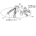
図1は、MU−MIMO伝送が適用されるHetnetの一例を示す図である。図1に示すシステムは、無線基地局装置(例えば、eNB:eNodeB)のカバレッジエリア内に局所的なカバレッジエリアを有する小型基地局装置(例えば、RRH:Remote Radio Head)が設けられ、階層的に構成されている。このようなシステムにおける下りリンクのMU−MIMO伝送では、無線基地局装置の複数のアンテナから複数のユーザ端末UE(User Equipment)#1及び#2に対するデータが同時に送信される。また、複数の小型基地局装置の複数のアンテナから複数のユーザ端末UE#3、#4に対するデータも同時に送信される。 FIG. 1 is a diagram illustrating an example of Hetnet to which MU-MIMO transmission is applied. The system shown in FIG. 1 is provided with a small base station apparatus (for example, RRH: Remote Radio Head) having a local coverage area within a coverage area of a radio base station apparatus (for example, eNB: eNodeB), and hierarchically. It is configured. In downlink MU-MIMO transmission in such a system, data for a plurality of user terminals UE (User Equipment) # 1 and # 2 are simultaneously transmitted from a plurality of antennas of a radio base station apparatus. Further, data for a plurality of user terminals UE # 3 and # 4 are simultaneously transmitted from a plurality of antennas of a plurality of small base station apparatuses.
図2は、下りリンクのMU−MIMO伝送が適用される無線フレーム(例えば、1サブフレーム)の一例を示す図である。図2に示すように、MU−MIMO伝送が適用されるシステムでは、各サブフレームにおいて先頭から所定のOFDMシンボル(1〜3OFDMシンボル)まで、下り制御チャネル(PDCCH:Physical Downlink Control Channel)用のリソース領域(PDCCH領域)として確保される。また、サブフレームの先頭から所定のシンボルより後の無線リソースに、下り共有データチャネル(PDSCH:Physical Downlink Shared Channel)用のリソース領域(PDSCH領域)が確保される。 FIG. 2 is a diagram illustrating an example of a radio frame (for example, one subframe) to which downlink MU-MIMO transmission is applied. As shown in FIG. 2, in a system to which MU-MIMO transmission is applied, resources for a downlink control channel (PDCCH: Physical Downlink Control Channel) from the beginning to a predetermined OFDM symbol (1 to 3 OFDM symbols) in each subframe It is secured as a region (PDCCH region). Also, a resource region (PDSCH region) for a downlink shared data channel (PDSCH) is secured in a radio resource after a predetermined symbol from the top of the subframe.
PDCCH領域には、ユーザ端末UE(ここでは、UE#1〜#4)に対する下り制御情報(DCI:Downlink Control Information)が割当てられる。下り制御情報(DCI)には、PDSCH領域における割当て情報が含まれる。このように、各サブフレームにおいて、ユーザ端末UEに対する下りデータ用の信号と、当該下りデータを受信するための下り制御情報(DCI)用の信号とは時分割多重されて送信される。 Downlink control information (DCI: Downlink Control Information) for user terminals UE (here, UE # 1 to # 4) is allocated to the PDCCH region. The downlink control information (DCI) includes allocation information in the PDSCH region. Thus, in each subframe, the signal for downlink data for the user terminal UE and the signal for downlink control information (DCI) for receiving the downlink data are time-division multiplexed and transmitted.
MU−MIMO伝送においては、同一時間及び同一周波数で複数のユーザ端末UEに対するデータ送信が可能となる。このため、図2のPDSCH領域において、ユーザ端末UE#1に対するデータとユーザ端末UE#5に対するデータを同一の周波数領域に多重することが考えられる。同様に、ユーザ端末UE#4に対するデータとユーザ端末UE#6に対するデータを同一の周波数領域に多重することも考えられる。
In MU-MIMO transmission, data transmission to a plurality of user terminals UE can be performed at the same time and the same frequency. For this reason, in the PDSCH region of FIG. 2, it is conceivable to multiplex data for the user
しかしながら、多くのユーザ端末UEの下り制御情報をPDCCH領域に割当てる場合、図2に示すように、ユーザ端末UE#5及び#6に対応する下り制御情報を伝送するためのPDCCH領域が足りなくなる場合がある。この場合には、PDSCH領域に多重できるユーザ端末UEの数が制限されてしまう。
However, when allocating the downlink control information of many user terminals UE to the PDCCH region, as shown in FIG. 2, the PDCCH region for transmitting the downlink control information corresponding to the user
このように、MU−MIMO伝送により同一の無線リソースに多重されるユーザ端末数を増加させても、下り制御情報を伝送するためのPDCCH領域が不足する場合には、PDSCH領域の利用効率を十分に図れないおそれがある。 Thus, even when the number of user terminals multiplexed on the same radio resource by MU-MIMO transmission is increased, if the PDCCH region for transmitting downlink control information is insufficient, the PDSCH region utilization efficiency is sufficiently increased. There is a risk that it may not be possible.
このようなPDCCH領域の不足を解決する方法として、サブフレームの先頭から最大3OFDMシンボルの制御領域以外にPDCCHの割当て領域を拡張する(既存のPDSCH領域にPDCCH領域を拡張する)ことが考えられる。例えば、PDSCH領域においてPDSCHとPDCCHとを周波数分割多重する方法(周波数分割(FDM)アプローチ)が考えられる。このようなPDSCHと周波数分割多重されるPDCCHは、既存のPDCCHと区別するために、拡張PDCCH(拡張下り制御チャネル、E−PDCCH、Enhanced PDCCH、FDM型PDCCH、UE−PDCCH等とも呼ぶ)と呼ばれる。 As a method for solving such a shortage of PDCCH regions, it is conceivable to extend the PDCCH allocation region other than the control region of up to 3 OFDM symbols from the beginning of the subframe (extend the PDCCH region to the existing PDSCH region). For example, a method of frequency division multiplexing (frequency division (FDM) approach) of PDSCH and PDCCH in the PDSCH region is conceivable. Such PDCCH frequency-division multiplexed with PDSCH is called enhanced PDCCH (also called enhanced downlink control channel, E-PDCCH, Enhanced PDCCH, FDM type PDCCH, UE-PDCCH, etc.) to distinguish it from existing PDCCH. .
周波数分割アプローチを適用する場合、ユーザ固有の参照信号(DM−RS:DeModulation-Reference Signal)を用いて拡張PDCCHの復調を行うことでビームフォーミングゲインを得ることが可能となる。この場合、ユーザ端末UEに対して個別にビームフォーミングが可能となることによって十分な受信品質が得られるため、容量の増大に有効となると考えられる。 When applying the frequency division approach, it is possible to obtain a beamforming gain by demodulating the extended PDCCH using a user-specific reference signal (DM-RS: DeModulation-Reference Signal). In this case, since sufficient reception quality can be obtained by individually performing beam forming for the user terminal UE, it is considered effective for increasing the capacity.
ところで、拡張PDCCHのフォーマットとしては、既存のPDCCHと同様に各ユーザの下り制御信号を複数のリソース要素グループ(REG)からなる制御チャネル要素(CCE)単位で割当てる方法(with cross interleaving)と、各ユーザの下り制御信号をPRB単位で割当てる方法(without cross interleaving)のいずれかが適用できる。 By the way, as the format of the extended PDCCH, a method (with cross interleaving) of assigning each user's downlink control signal in units of control channel elements (CCE) composed of a plurality of resource element groups (REG), as in the existing PDCCH, Any of the methods (without cross interleaving) of assigning the user's downlink control signal in units of PRBs can be applied.
without cross interleavingでは、拡張PDCCHに対して、各ユーザの下りリンク制御信号がVRB単位で割当てられる。また、拡張PDCCHが配置される可能性のある無線リソースにはユーザ個別の下り参照信号であるDM−RSが配置される。このため、拡張PDCCHの復調をDM−RSを用いて行うことができる。この場合、PRB単位でのチャネル推定が可能であり、各移動端末装置UEに対して効果的にビームフォーミングを形成できる。 In without cross interleaving, the downlink control signal of each user is assigned to the extended PDCCH in units of VRBs. Also, DM-RSs, which are user-specific downlink reference signals, are arranged in radio resources in which the extended PDCCH may be arranged. For this reason, demodulation of extended PDCCH can be performed using DM-RS. In this case, channel estimation in units of PRB is possible, and beam forming can be effectively formed for each mobile terminal apparatus UE.
図3に、周波数分割アプローチを適用する場合のフレーム構成の一例を示す。図3Aに示すフレーム構成では、既存のPDCCHと拡張PDCCHが配置されている。送信時間間隔となるフレーム(以下、「サブフレーム」と記す)の先頭から所定のOFDMシンボル(最大3OFDMシンボル)まではシステム帯域全体にわたり既存のPDCCHが配置される。既存のPDCCHが配置されたOFDMシンボルより後の無線リソースに、拡張PDCCHがPDSCHと周波数分割して配置されている。 FIG. 3 shows an example of a frame configuration when applying the frequency division approach. In the frame configuration shown in FIG. 3A, an existing PDCCH and an extended PDCCH are arranged. Existing PDCCHs are arranged over the entire system band from the beginning of a frame (hereinafter referred to as “subframe”) serving as a transmission time interval to a predetermined OFDM symbol (maximum 3 OFDM symbols). An extended PDCCH is frequency-divided with the PDSCH in radio resources after the OFDM symbol in which the existing PDCCH is allocated.
また、図3Bに示すように、システム帯域は所定の周波数領域単位で構成される。この所定の周波数領域単位としては、例えば、物理リソースブロック(PRB)(単に、リソースブロック(RB)ともいう)や、複数の連続する物理リソースブロックからなるリソースブロックグループ(RBG)などがある。図3Bでは、所定の周波数領域単位としてリソースブロックが用いられており、システム帯域の一部のリソースブロックが拡張PDCCHに割り当てられる。なお、リソースブロックは、スケジューリングの一単位でもある。 As shown in FIG. 3B, the system band is configured in units of a predetermined frequency domain. Examples of the predetermined frequency domain unit include a physical resource block (PRB) (also simply referred to as a resource block (RB)) and a resource block group (RBG) including a plurality of continuous physical resource blocks. In FIG. 3B, resource blocks are used as predetermined frequency domain units, and some resource blocks in the system band are allocated to the extended PDCCH. A resource block is also a unit of scheduling.
また、Rel.11以降のフレーム構成として、サブフレームにおいて先頭から所定のOFDMシンボル(最大3OFDMシンボル)までのPDCCH領域を持たないキャリアタイプ(Extension carrier)が検討されている。このExtension carrierタイプが適用されるサブフレームでは、既存PDCCHを割当てず、拡張PDCCHのみを割り当てることができる。なお、Extension carrierタイプが適用されるサブフレームでは、先頭から最大3OFDMシンボルにおいて拡張PDCCHが割り当てられてもよい(図3C参照)。 Also, Rel. As a frame configuration after 11, a carrier type (Extension carrier) that does not have a PDCCH region from the beginning to a predetermined OFDM symbol (maximum 3 OFDM symbols) in a subframe is being studied. In a subframe to which this extension carrier type is applied, only an extended PDCCH can be allocated without allocating an existing PDCCH. Note that in a subframe to which the extension carrier type is applied, an extended PDCCH may be allocated in up to 3 OFDM symbols from the top (see FIG. 3C).
このような周波数分割アプローチを適用する場合、拡張PDCCHをシステム帯域にどのようにマッピングするかが問題となる。上述のように、拡張PDCCHは、PDSCHと周波数分割多重され、システム帯域の一部にマッピングされるためである。 When such a frequency division approach is applied, a problem is how to map the extended PDCCH to the system band. This is because the extended PDCCH is frequency-division multiplexed with the PDSCH and mapped to a part of the system band as described above.
図4に、拡張PDCCHのマッピングの一例を示す。図4では、11個の物理リソースブロック(PRB:Physical Resource Block)でシステム帯域が構成されている。11個のPRBには、周波数方向に沿ってPRBインデックス(PRB#0〜#10)が付されている。図4において、拡張PDCCHは、不連続の4個のPRB#1、#4、#8、#10にマッピングされる。このように、拡張PDCCHを不連続の4個のPRBにマッピングすることで拡張PDCCHをシステム帯域内に分散させることができる。この結果、拡張PDCCHについての周波数ダイバーシチ効果を得ることができる。
FIG. 4 shows an example of extended PDCCH mapping. In FIG. 4, the system band is composed of 11 physical resource blocks (PRB). The 11 PRBs are assigned PRB indexes (
なお、図4では、拡張PDCCHは、PRB単位でマッピングされているが、これに限られるものではない。例えば、連続する複数のPRB(例えば、2個又は4個のPRB)からなるRBG(Resource Block Group)単位で行われてもよい。 In FIG. 4, the extended PDCCH is mapped in units of PRBs, but is not limited to this. For example, it may be performed in RBG (Resource Block Group) units composed of a plurality of continuous PRBs (for example, two or four PRBs).
ところで、既存のPDCCHでは、ユーザ端末UEが下り制御情報(DCI)のブラインドデコーディングを行う範囲を示すサーチスペース(SS)が定義されている。ユーザ端末UEは、無線基地局装置からシグナリングされた(例えば、RRCシグナリング)サーチスペース内でブラインドデコーディングを行う。 By the way, in the existing PDCCH, a search space (SS) indicating a range in which the user terminal UE performs blind decoding of downlink control information (DCI) is defined. The user terminal UE performs blind decoding in a search space signaled from the radio base station apparatus (for example, RRC signaling).
このようなサーチスペースの種類としては、共通サーチスペース(CSS:Common Search Space)とUE固有サーチスペース(UE−SS:UE-specific Search Space)(固有サーチスペースともいう)とがある。共通サーチスペースとは、セル内のユーザ端末UEが共通制御情報をブラインドデコーディングすべき範囲を示すものである。また、UE固有サーチスペースとは、各ユーザ端末UEが固有制御情報をブラインドデコーディングすべき範囲を示すものである。 Examples of such search spaces include a common search space (CSS) and a UE-specific search space (UE-SS) (also referred to as a unique search space). The common search space indicates a range in which the user terminal UE in the cell should blind-decode common control information. The UE-specific search space indicates a range in which each user terminal UE should blind-decode specific control information.
なお、共通制御情報とは、セル内のユーザ端末UEに共通の下り制御情報であり、例えば、DCIフォーマット0、1A等で定義される情報である。また、固有制御情報とは、セル内の各ユーザ端末UEに固有の下り制御情報であり、例えば、下り共有データチャネルの割り当て情報(DL Assignment)や、上り共有データチャネルのスケジューリング情報(UL grant)などが含まれる。 Note that the common control information is downlink control information common to the user terminals UE in the cell, and is information defined in, for example, DCI formats 0 and 1A. The unique control information is downlink control information unique to each user terminal UE in the cell. For example, downlink shared data channel assignment information (DL Assignment) and uplink shared data channel scheduling information (UL grant) Etc. are included.
以上のようなサーチスペースは、既存のPDCCHの割り当て単位である制御チャネル要素(CCE:Channel Control Element)と、既存のPDCCHに対してCCEを何個連続で割り当てられるかを示すアグリゲーションレベル(Aggregation Level)とによって定義される。例えば、アグリゲーションレベル1では1CCE単位で、アグリゲーションレベル2では2CCE単位で、アグリゲーションレベル3では4CCE単位で、アグリゲーションレベル4では8CCE単位で、サーチスペースが定義される。なお、共通サーチスペースは、アグリゲーションレベル3、4をサポートし、UE固有サーチスペースは、アグリゲーションレベル1〜4をサポートする。また、アグリゲーションレベルは、ユーザ端末UEにおける信号の受信品質に基づいて決定される。
The search space as described above includes a control channel element (CCE: Channel Control Element) that is an existing PDCCH allocation unit and an aggregation level (Aggregation Level) indicating how many CCEs can be continuously allocated to the existing PDCCH. ) And For example, the search space is defined in units of 1 CCE at
既存のPDCCHでは、以上のようなサーチスペースが定義されることにより、ユーザ端末UEにおけるブラインドデコーディングの回数を削減できる。したがって、without cross interleavingを適用する拡張PDCCHにおいても、ユーザ端末UEにおけるブラインドデコーディングの回数を削減するために、共通サーチスペースとUE固有サーチスペースとを定義することが望まれていた。そこで、本発明者らは、拡張PDCCHにおける共通サーチスペースとUE固有サーチスペースのマッピングについて検討し、本願発明に至った。 In the existing PDCCH, the number of times of blind decoding in the user terminal UE can be reduced by defining the search space as described above. Therefore, in the extended PDCCH to which without cross interleaving is applied, in order to reduce the number of times of blind decoding in the user terminal UE, it is desired to define a common search space and a UE-specific search space. Therefore, the present inventors examined mapping between the common search space and the UE-specific search space in the extended PDCCH, and reached the present invention.
(第1の態様)
図5〜図7を参照して、第1の態様に係る拡張PDCCHのマッピング方法の一例について説明する。なお、以下では、拡張PDCCHをRBG単位でマッピングする例を示すが、これに限られるものではない。
(First aspect)
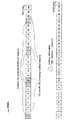
With reference to FIG. 5 to FIG. 7, an example of the extended PDCCH mapping method according to the first aspect will be described. In the following, an example in which extended PDCCH is mapped in units of RBGs is shown, but the present invention is not limited to this.
図5に、第1の態様に係る拡張PDCCHのマッピングの一例を示す。図5では、100Mhzのシステム帯域の例が示されており、周波数方向に100個のPRB(不図示)が連続して配置される。ここで、システム帯域が100個のPRBで構成される場合、1つのRBGは4個の連続するPRBで構成される。よって、図5では、25個のRBGが示されている。また、25個のRBGには、周波数方向に沿ってRBGインデックス(RBG#0〜#24)が付されている。
FIG. 5 shows an example of extended PDCCH mapping according to the first aspect. FIG. 5 shows an example of a system band of 100 Mhz, and 100 PRBs (not shown) are continuously arranged in the frequency direction. Here, when the system band is composed of 100 PRBs, one RBG is composed of 4 consecutive PRBs. Therefore, in FIG. 5, 25 RBGs are shown. 25 RBGs are assigned RBG indexes (
なお、システム帯域、PRBの数、1つのRBGを構成するPRBの数は、図5に示す例に限られるものではない。例えば、システム帯域が25個のPRBで構成される場合、1つのRBGは2つの連続するPRBで構成され、13個のRBGが示される。 Note that the system band, the number of PRBs, and the number of PRBs constituting one RBG are not limited to the example shown in FIG. For example, when the system band is composed of 25 PRBs, one RBG is composed of two consecutive PRBs, and 13 RBGs are shown.
図5に示すように、無線基地局装置は、共通制御情報が配置される共通サーチスペースと固有制御情報が配置されるUE固有サーチスペースとを、システム帯域を構成するRBG単位で分離してマッピングする。具体的には、共通サーチスペースは、システム帯域全体に分散されるように、不連続の4個のRBG(RBG#0、#7、#14、#21)にマッピングされる。また、UE固有サーチスペースは、システム帯域全体に分散されるように、不連続の4個のRBG(RBG#1、#8、#15、#22)にマッピングされる。
As shown in FIG. 5, the radio base station apparatus maps the common search space where the common control information is arranged and the UE specific search space where the unique control information is arranged separately for each RBG constituting the system band. To do. Specifically, the common search space is mapped to four discontinuous RBGs (
共通サーチスペースに配置される共通制御情報は、上述のように、セル内のユーザ端末に共通の下り制御情報であるので、周波数ダイバーシチ効果が得られるように、分散された周波数帯域で送信されることが望ましい。このため、共通サーチスペースは、システム帯域全体に分散された不連続の所定数のRBG(図5では、4個のRBG#0、#7、#14、#21)に分散マッピングされる。
Since the common control information arranged in the common search space is downlink control information common to the user terminals in the cell as described above, it is transmitted in a distributed frequency band so as to obtain a frequency diversity effect. It is desirable. Therefore, the common search space is distributed and mapped to a predetermined number of discrete RBGs (four
また、UE固有サーチスペースに配置される固有制御情報は、各ユーザ端末UEに固有の下り制御情報であるので、対象のユーザ端末UEにとって最も受信品質が良い周波数帯域で局所的に送信されることが望ましい。このため、UE固有サーチスペースは、システム帯域全体に分散された不連続の所定数のRBG(図5では、4個のRBG#1、#8、#15、#22)に分散マッピングされるが、固有制御情報は、所定のRBGに局所的にマッピングされる。また、受信品質が利用できない場合は、分散マッピングを適用してもよい。
In addition, since the unique control information arranged in the UE-specific search space is downlink control information unique to each user terminal UE, it must be locally transmitted in a frequency band with the best reception quality for the target user terminal UE. Is desirable. For this reason, the UE-specific search space is distributed and mapped to a predetermined number of discrete RBGs (four
図5に示す共通サーチスペース及びUE固有サーチスペースのマッピング位置は、上位レイヤ(例えば、RRCレイヤなど)で、ユーザ端末UEにシグナリングされる。このマッピング位置のシグナリングには、ビットマップ(例えば、図5では、25個のRBGを示す25ビットのビットマップ)が用いられてもよい。 The mapping positions of the common search space and the UE-specific search space shown in FIG. 5 are signaled to the user terminal UE in an upper layer (for example, RRC layer). For the mapping position signaling, a bitmap (for example, a 25-bit bitmap indicating 25 RBGs in FIG. 5) may be used.
また、共通サーチスペースのマッピング位置は、報知情報(例えば、MIBやSIBなど)として、ユーザ端末UEにブロードキャスト送信されてもよい。共通サーチスペースのマッピング位置は、セル内のユーザ端末UEに共通であるためである。この場合にも、ビットマップが用いられてもよい。 Further, the mapping position of the common search space may be broadcasted to the user terminal UE as broadcast information (for example, MIB or SIB). This is because the mapping position of the common search space is common to the user terminals UE in the cell. Also in this case, a bitmap may be used.
なお、図5では、共通サーチスペース及びUE固有サーチスペースは、RBG単位で分離してマッピングされるが、これに限られるものではない。例えば、共通サーチスペース及びUE固有サーチスペースは、PRB単位で分離してマッピングされてもよい。 In FIG. 5, the common search space and the UE-specific search space are mapped separately in RBG units, but the present invention is not limited to this. For example, the common search space and the UE-specific search space may be mapped separately for each PRB.
また、図5では、共通サーチスペース及びUE固有サーチスペースがマッピングされるRBGの数はそれぞれ4個であるが、これに限られるものではない。また、共通サーチスペース及びUE固有サーチスペースがマッピングされる複数のRBGの一部は連続していてもよい。 In FIG. 5, the number of RBGs to which the common search space and the UE-specific search space are mapped is four, but is not limited thereto. Further, a part of the plurality of RBGs to which the common search space and the UE-specific search space are mapped may be continuous.
次に、図6及び図7を参照し、第1の態様に係る拡張PDCCHの共通サーチスペースの分散マッピングについて詳述する。なお、図6及び図7では、図5と同様に、100MHzのシステム帯域の例が示される。また、図6及び図7では、共通サーチスペースがRBG単位で分散マッピングされる例を説明するが、PRB単位で分散マッピングされてもよい。 Next, with reference to FIG.6 and FIG.7, the distributed mapping of the common search space of the extended PDCCH which concerns on a 1st aspect is explained in full detail. 6 and 7 show an example of a system bandwidth of 100 MHz as in FIG. 6 and 7 illustrate an example in which the common search space is distributedly mapped in units of RBGs, but may be distributedly mapped in units of PRBs.
図6では、不連続の4個のRBG(RBG#0、#7、#14、#21)に分散マッピングされた共通サーチスペースと、拡張制御チャネル要素(eCCE:enhanced Channel Control Element)との対応付けが示される。上述のように、既存のPDCCHに対する最小割り当て単位はCCEである。拡張PDCCHでは、既存のCCEをリユースできるように、eCCEが定義される。すなわち、拡張PDCCHに対する最小割り当て単位は、eCCEとなる。このため、拡張PDCCHの共通サーチスペースはeCCE単位で管理される。
In FIG. 6, the correspondence between the common search space distributedly mapped to four discontinuous RBGs (
図6において、1個のRBGは4個のRB(PRB)で構成される。1個のRB(PRB)は2個のeCCEに対応する。このため、4個のRBGにマッピングされた共通サーチスペースは、4×4×2=32個のeCCEで定義されることになる。図6では、周波数方向に沿ってRBGインデックス#0、#7、#14、#21の小さい方から順番にeCCEにインデックス番号#0〜#31をナンバリングしている。なお、1個のPRBを構成するeCCEの数は、2個に限定されず、その他の数(例えば、4個)としてもよい。
In FIG. 6, one RBG is composed of four RBs (PRB). One RB (PRB) corresponds to two eCCEs. Therefore, the common search space mapped to the four RBGs is defined by 4 × 4 × 2 = 32 eCCEs. In FIG. 6,
第1の態様では、拡張PDCCHにおける共通サーチスペースを構成するeCCEをそれぞれ分割して、分割されたeCCE同士が周波数帯域の異なるRBGにそれぞれ分散されるようにマッピングする。これにより、共通サーチスペースで伝送される共通制御情報について、周波数ダイバーシチ効果が得られることとなる。 In the first mode, the eCCEs constituting the common search space in the extended PDCCH are divided, and the divided eCCEs are mapped so as to be distributed to RBGs having different frequency bands. Thereby, the frequency diversity effect is obtained for the common control information transmitted in the common search space.
具体的には、図7Aに示すように、無線基地局装置は、共通サーチスペースとして割り当てられたeCCE#0〜#31をそれぞれ2個に分割する。1eCCEを2個に分割する場合、1個のRBG(例えば、RBG#0)に対して、16個のeCCE(例えば、eCCE#0、#0、#1、#1、…#7、#7)が対応することとなる。
Specifically, as illustrated in FIG. 7A, the radio base station apparatus divides
次に、図7Bに示すように、図7Aで分割されたeCCEが、複数の仮想リソース領域に分散配置される。図7Bでは、仮想リソース領域として4つの仮想リソースブロックグループ(VRBG)#1〜#4が定義され、図7Aに示す64個のeCCEがVRBG#1〜#4に分散配置される。
Next, as shown in FIG. 7B, the eCCEs divided in FIG. 7A are distributed and arranged in a plurality of virtual resource areas. In FIG. 7B, four virtual resource block groups (VRBG) # 1 to # 4 are defined as virtual resource areas, and 64 eCCEs shown in FIG. 7A are distributed and arranged in
具体的には、図7Aにおいて同じインデックス番号が付されたeCCEは、図7Bにおいて異なるインデックス番号のVRBGに配置される。例えば、同じインデックス番号が付された2個のeCCE#0は、VRBG#1とVRBG#2に配置される。同様に、2個のeCCE#1は、VRBG#3とVRBG#4に配置される。eCCE#2〜#31についても同様である。
Specifically, eCCEs with the same index number in FIG. 7A are arranged in VRBGs with different index numbers in FIG. 7B. For example, two eCCE # 0s with the same index number are arranged in
図7Cに示すように、eCCEが分散配置された複数の仮想リソース領域(VRBG#1〜#4)は、インタリーブされ、元のRBG#0、#7、#14、#21にマッピングされる。図7Cでは、奇数インデックス番号のVRBGを元のRBGに昇順にマッピングしてから、偶数インデックス番号のVRBGを元のRBGに昇順にマッピングする例が示される。すなわち、VRBG#1は元のRBG#0に、VRBG#2は元のRBG#7に、VRBG#3は元のRBG#14に、VRBG#4は元のRBG#21にマッピングされる。
As shown in FIG. 7C, a plurality of virtual resource areas (
図7Cに示すように、VRBGをインタリーブして元のRBGにマッピングすることにより、同じインデックス番号が付されたeCCEペア間の周波数間隔を拡大することができるため、共通サーチスペースの周波数ダイバーシチ効果を得ることができる。 As shown in FIG. 7C, by interleaving the VRBG and mapping it to the original RBG, the frequency interval between eCCE pairs with the same index number can be expanded, so that the frequency diversity effect of the common search space can be reduced. Can be obtained.
なお、図6及び図7で説明した分散マッピング方法は、共通サーチスペースだけではなく、UE固有サーチスペースに適用されてもよい。 Note that the distributed mapping method described in FIGS. 6 and 7 may be applied not only to the common search space but also to the UE-specific search space.
以上のように、第1の態様に係る拡張PDCCHのマッピング方法によれば、無線基地局装置は、共通サーチスペースとUE固有サーチスペースとを、PRB単位又はRBG単位で分離してマッピングする。特に、無線基地局装置は、セル内の全ユーザ端末UEの共通制御情報が配置される共通サーチスペースを、システム帯域内に分散されるように複数の周波数領域単位(PRB又はRBG)にマッピングする。このため、周波数ダイバーシチ効果により、セル内の異なる位置に位置するユーザ端末UEが安定して共通制御情報を復号できる。また、無線基地局装置は、特定のユーザ端末UEに固有の固有制御情報が配置されるUE固有サーチスペースを、システム帯域内の一部に局所化されるように複数の周波数領域単位(PRB又はRBG)にマッピングする。このため、特定のユーザ端末UEはより受信品質の良い周波数領域単位(PRB又はRBG)で固有制御情報を復号できる。また、受信品質が利用できない場合は、分散マッピングを適用してもよい。 As described above, according to the extended PDCCH mapping method according to the first aspect, the radio base station apparatus separates and maps the common search space and the UE-specific search space in units of PRBs or RBGs. In particular, the radio base station apparatus maps a common search space in which common control information of all user terminals UE in a cell is arranged to a plurality of frequency domain units (PRB or RBG) so as to be distributed in the system band. . For this reason, the user terminal UE located in a different position in the cell can stably decode the common control information due to the frequency diversity effect. In addition, the radio base station apparatus has a plurality of frequency domain units (PRB or PRB) so that a UE specific search space in which specific control information specific to a specific user terminal UE is arranged is localized in a part of the system band. RBG). For this reason, the specific user terminal UE can decode the unique control information in a frequency domain unit (PRB or RBG) with better reception quality. Further, when the reception quality cannot be used, distributed mapping may be applied.
特に、HetNetの小型基地局装置に上述のマッピング方法を適用することで、小型基地局装置は、ユーザ端末UEに対して、大型基地局装置からCRS等による干渉の影響が大きい既存PDCCHでなく、干渉の影響が小さい拡張PDCCHを用いて共通制御情報と固有制御情報を送信することができる。より具体的には、拡張PDCCHにおいては、DM−RSによるビームフォーミング効果が得られるので、後述するCRE(Cell Range Expansion)により小型基地局装置に接続するユーザ端末UEが、拡張PDCCHに配置された共通サーチスペースをより効果的にブラインドデコーディングすることができる。この結果、HetNetにおける干渉コーディネーションが可能となる。また、Low cost MTC Deviceにも適合することとなる。また、受信品質が利用できない場合は、分散マッピングを適用してもよい。 In particular, by applying the above mapping method to a small base station device of HetNet, the small base station device is not an existing PDCCH that is greatly affected by interference from the large base station device by CRS or the like to the user terminal UE, Common control information and unique control information can be transmitted using an extended PDCCH that is less affected by interference. More specifically, since the beam forming effect by DM-RS is obtained in the extended PDCCH, the user terminal UE connected to the small base station apparatus by CRE (Cell Range Expansion) described later is arranged in the extended PDCCH. The common search space can be more effectively blind-decoded. As a result, interference coordination in HetNet becomes possible. It will also be compatible with Low cost MTC Device. Further, when the reception quality cannot be used, distributed mapping may be applied.
(第2の態様)
図8〜図12を参照して、第2の態様に係る拡張PDCCHのマッピング方法の一例について説明する。第2の態様は、拡張PDCCHの共通サーチスペースについて、HetNetにより適合したマッピング方法とするものである。よって、第1の態様に係る拡張PDCCHのマッピング方法に第2の態様を組み合わせることも可能である。
(Second aspect)
With reference to FIGS. 8-12, an example of the mapping method of the extended PDCCH which concerns on a 2nd aspect is demonstrated. The second mode is a mapping method adapted by HetNet for the common search space of the extended PDCCH. Therefore, it is also possible to combine the second mode with the extended PDCCH mapping method according to the first mode.
HetNetでは、CRE(Cell Range Expansion)を行って、小型基地局装置のセル端に位置するユーザ端末UEを小型基地局装置に接続させることが検討されている。図8に、HetNetにおけるCREの一例を示す。図8では、無線基地局装置(マクロ基地局B1)の形成するセルC1内に、局所的なセルC2を形成する小型基地局装置(ピコ基地局B2)が配置されている。 In HetNet, it is considered to perform CRE (Cell Range Expansion) to connect the user terminal UE located at the cell edge of the small base station apparatus to the small base station apparatus. FIG. 8 shows an example of CRE in HetNet. In FIG. 8, a small base station apparatus (pico base station B2) that forms a local cell C2 is arranged in a cell C1 formed by a radio base station apparatus (macro base station B1).
図8に示すように、HetNetにおけるCREでは、ピコ基地局B2からの受信電力にオフセット値を与えることでピコ基地局B2のセル範囲をセルC2’に拡大し、セルC2のセル端に位置するユーザ端末UEをピコ基地局B2に接続させる。こうすることにより、送信電力の小さなピコ基地局B2のカバレッジを増大することができ、より多くのユーザ端末UEをピコ基地局に接続することができる。 As shown in FIG. 8, in the CRE in HetNet, the cell range of the pico base station B2 is expanded to the cell C2 ′ by giving an offset value to the received power from the pico base station B2, and located at the cell edge of the cell C2. The user terminal UE is connected to the pico base station B2. By carrying out like this, the coverage of pico base station B2 with small transmission power can be increased, and more user terminals UE can be connected to a pico base station.
一方、ユーザ端末UEがCREによってピコ基地局B2に接続された場合、ユーザ端末UEは、マクロ基地局B1からの干渉を大きく受けることになる。このような干渉を防ぐため、ピコ基地局B2からユーザ端末UEに対する信号が送信されるサブフレームにおいて、マクロ基地局B1は、ABS(Almost Blank Subframe)やMBSFNサブフレームを適用する。 On the other hand, when the user terminal UE is connected to the pico base station B2 by CRE, the user terminal UE receives a large amount of interference from the macro base station B1. In order to prevent such interference, the macro base station B1 applies an ABS (Almost Blank Subframe) or an MBSFN subframe in a subframe in which a signal is transmitted from the pico base station B2 to the user terminal UE.
ところが、ABSやMBSFNサブフレームでは、データ(例えば、PDSCH)の送信が停止されるものの、参照信号(Cell specific reference signal(CRS))や、同期信号、報知チャネルなどは送信される。このため、ユーザ端末UEがCREによりピコ基地局B2に接続された場合、マクロ基地局B1がABSやMBSFNサブフレームを適用していても、図8に示すように、マクロ基地局B1からのCRS等による干渉を大きく受けることとなる。 However, in the ABS or MBSFN subframe, transmission of data (for example, PDSCH) is stopped, but a reference signal (Cell specific reference signal (CRS)), a synchronization signal, a broadcast channel, and the like are transmitted. Therefore, when the user terminal UE is connected to the pico base station B2 by CRE, even if the macro base station B1 applies the ABS or MBSFN subframe, as shown in FIG. 8, the CRS from the macro base station B1 It will be greatly affected by interference.
このようなマクロ基地局B1からのCRS等による干渉の影響は、ピコ基地局B2からユーザ端末UEに対する既存のPDCCHにおいてより顕著なものとなる。そこで、ピコ基地局B2では、マクロ基地局B1からの干渉の影響を軽減できる拡張PDCCHにおいて、共通サーチスペースを定義することが有効となる。 The influence of such interference due to CRS or the like from the macro base station B1 becomes more prominent in the existing PDCCH from the pico base station B2 to the user terminal UE. Therefore, in the pico base station B2, it is effective to define a common search space in the extended PDCCH that can reduce the influence of interference from the macro base station B1.
このように、HetNetにおいて、マクロ基地局B1とピコ基地局B2との双方が拡張PDCCHにおいて共通サーチスペースを定義する場合、マクロ基地局B1とピコ基地局B2との間の干渉コーディネーションが重要な問題となる。第2の態様に係る拡張PDCCHのマッピング方法では、マクロ基地局B1とピコ基地局B2との間の干渉コーディネーションを可能とする、共通サーチスペースのマッピングを検討する。 Thus, in HetNet, when both the macro base station B1 and the pico base station B2 define a common search space in the extended PDCCH, the interference coordination between the macro base station B1 and the pico base station B2 is an important problem. It becomes. In the extended PDCCH mapping method according to the second aspect, a common search space mapping that enables interference coordination between the macro base station B1 and the pico base station B2 is considered.
図9及び図10を参照し、第2の態様に係る拡張PDCCHの共通サーチスペースのマッピングの一例を詳述する。なお、図9及び図10では、図5〜7と同様に、100MHzのシステム帯域の例が示される。また、図9及び図10では、共通サーチスペースがRBG単位でマッピングされる例を説明するが、これに限られるものではなく、例えば、PRB単位でマッピングされてもよい。また、図9において、不図示のUE固有サーチスペースがマッピングされていてもよい。 With reference to FIG.9 and FIG.10, an example of mapping of the common search space of the extended PDCCH which concerns on a 2nd aspect is explained in full detail. 9 and 10 show examples of a system band of 100 MHz as in FIGS. 9 and 10 illustrate an example in which the common search space is mapped in RBG units, but the present invention is not limited to this, and may be mapped in PRB units, for example. In FIG. 9, a UE-specific search space (not shown) may be mapped.
図9に示すように、HetNetのマクロ基地局B1及びピコ基地局B2は、拡張PDCCHの共通サーチスペースを、共通の複数のRBG(RBG#0、#7、#14、#21)にマッピングする。すなわち、図9では、マクロ基地局B1とピコ基地局B2との双方において、複数のRBG(RBG#0、#7、#14、#21)が共通サーチスペース用に割り当てられる。
As shown in FIG. 9, the HetNet macro base station B1 and the pico base station B2 map the common search space of the extended PDCCH to a plurality of common RBGs (
一方、複数のRBGを構成するeCCEは、マクロ基地局B1とピコ基地局B2との間で別々に割り当てられる。具体的には、マクロ基地局B1に対しては、所定の周波数方向(図9では、周波数の小さい方向)から順番に連続するインデックス番号が付された複数のeCCE(eCCE#0〜#15)が割り当てられる。また、ピコ基地局B2に対しては、残りの連続するインデックス番号が付された複数のeCCE(eCCE#16〜#31)が割り当てられる。
On the other hand, eCCEs constituting a plurality of RBGs are allocated separately between the macro base station B1 and the pico base station B2. Specifically, for the macro base station B1, a plurality of eCCEs (
このように、マクロ基地局B1とピコ基地局B2との間で、共通サーチスペースをマッピングする複数のRBGを共通させる一方、eCCEは別々とする。より具体的には、マクロ基地局B1に対して一方のeCCE、ピコ基地局B2に対して他方のeCCEが割り当てられる。この結果、共通サーチスペースをマッピングする複数のRBGを共通させても、以下の分散マッピングを適用することで、周波数ダイバーシチ効果を得ることができる。 In this way, the macro base station B1 and the pico base station B2 share a plurality of RBGs that map the common search space, while eCCEs are different. More specifically, one eCCE is assigned to the macro base station B1, and the other eCCE is assigned to the pico base station B2. As a result, even if a plurality of RBGs that map the common search space are shared, a frequency diversity effect can be obtained by applying the following distributed mapping.
分散マッピングでは、マクロ基地局B1用に割り当てられたeCCE#0〜#15、ピコ基地局B2用に割り当てられたeCCE#16〜#31をそれぞれ分割して、分割されたeCCE同士が周波数帯域の異なるRBGにそれぞれ分散されるようにマッピングする。これにより、マクロ基地局B1用の共通サーチスペースに配置される共通制御情報と、ピコ基地局B2用の共通サーチスペースに配置される共通制御情報とを、周波数帯域の異なるRBG#0、#7、#14、#21に分散させることができる。すなわち、マクロ基地局B1とピコ基地局B2との間の干渉の影響を軽減すると共に、共通制御情報の周波数ダイバーシチ効果を得ることができる。
In distributed mapping,
具体的には、図10Aに示すように、マクロ基地局B1は、マクロ基地局B1用に割り当てられたeCCE#0〜#15をそれぞれ2個に分割し、分割したeCCE同士に同じインデックス番号(図10Aでは、eCCE#0、#0…、#15、#15)を付す。同様に、ピコ基地局B2は、ピコ基地局B2用に割り当てられたeCCE#16〜#31をそれぞれ2個に分割し、分割したeCCE同士に同じインデックス番号(図10Aでは、eCCE#16、#16…、#31、#31)を付す。
Specifically, as shown in FIG. 10A, the macro base station B1 divides
次に、図10Bに示すように、図10Aで分割されたeCCEが、複数の仮想リソース領域に分散配置される。図10Bでは、仮想リソース領域として4つの仮想リソースブロックグループ(VRBG)#1〜#4が定義され、図10Aに示す64個のeCCEがVRBG#1〜#4に分散配置される。
Next, as shown in FIG. 10B, the eCCEs divided in FIG. 10A are distributed and arranged in a plurality of virtual resource areas. 10B, four virtual resource block groups (VRBG) # 1 to # 4 are defined as virtual resource areas, and 64 eCCEs shown in FIG. 10A are distributed and arranged in
具体的には、図10Aにおいて同じインデックス番号が付されたeCCEは、図10Bにおいて異なるインデックス番号のVRBGに配置される。さらに、マクロ基地局B1に割り当てられた32個のeCCEは、インデックス番号に基づいてVRBG#1〜#4に分散配置される。同様に、ピコ基地局B2に割り当てられた32個のeCCEは、インデックス番号に基づいてVRBG#1〜#4に分散配置される。例えば、図10Bでは、マクロ基地局B1及びピコ基地局B2に割り当てられた偶数インデックス番号のeCCEはVRBG#1及び#2に配置され、奇数インデックス番号のeCCEはVRBG#3及び#4に配置される。
Specifically, eCCEs with the same index number in FIG. 10A are arranged in VRBGs with different index numbers in FIG. 10B. Further, the 32 eCCEs assigned to the macro base station B1 are distributed and arranged in
図10Cに示すように、eCCEが分散配置された複数の仮想リソース領域(VRBG#1〜#4)は、インタリーブされ、元のRBG#0、#7、#14、#21にマッピングされる。図10Cでは、奇数インデックス番号のVRBGを元のRBGに昇順にマッピングしてから、偶数インデックス番号のVRBGを元のRBGに昇順にマッピングする例が示される。すなわち、VRBG#1は元のRBG#0に、VRBG#2は元のRBG#7に、VRBG#3は元のRBG#14に、VRBG#4は元のRBG#21にマッピングされる。
As shown in FIG. 10C, a plurality of virtual resource regions (
図10Cに示すように、VRBGをインタリーブしてRBGにマッピングすることにより、同じインデックス番号が付されたeCCEペア間の周波数間隔を拡大することができる。さらに、マクロ基地局B1用のeCCEペア間、ピコ基地局B2用のeCCEペア間の周波数間隔を拡大できるので、マクロ基地局B1の共通サーチスペースとピコ基地局B2の共通サーチスペースとの双方について、周波数ダイバーシチ効果を得ることができる。このようにマクロ基地局B1とピコ基地局B2でサーチスペースを別々に割当てることで、マクロ基地局B1とピコ基地局B2との間の干渉の影響を軽減しつつ、分散マッピングにより周波数ダイバーシチ効果が得られるため、マクロ基地局B1のセルC1内のユーザ端末UEとピコ基地局B2のセルC2内のユーザ端末UEとがそれぞれ安定して共通制御情報を復号可能となる。 As shown in FIG. 10C, by interleaving the VRBG and mapping it to the RBG, the frequency interval between the eCCE pairs with the same index number can be expanded. Furthermore, since the frequency interval between the eCCE pair for the macro base station B1 and the eCCE pair for the pico base station B2 can be expanded, both the common search space for the macro base station B1 and the common search space for the pico base station B2 A frequency diversity effect can be obtained. In this way, by assigning search spaces separately in the macro base station B1 and the pico base station B2, the frequency diversity effect is achieved by distributed mapping while reducing the influence of interference between the macro base station B1 and the pico base station B2. Accordingly, the user terminal UE in the cell C1 of the macro base station B1 and the user terminal UE in the cell C2 of the pico base station B2 can each stably decode the common control information.
以上のような第2の態様に係る拡張PDCCHのマッピング方法によれば、マクロ基地局B1とピコ基地局B2との間で、共通サーチスペースをマッピングする複数のRBGを共通させる一方、それぞれの共通サーチスペースをインデックス番号が異なるeCCEにマッピングする。このため、マクロ基地局B1とピコ基地局B2間の干渉を軽減しつつ,分散マッピングにより得られる周波数ダイバーシチ効果により、マクロ基地局B1のセルC1内に位置するユーザ端末UEとピコ基地局B2のセルC2内に位置するユーザ端末UEとがそれぞれ安定して共通制御情報を復号可能となる。 According to the extended PDCCH mapping method according to the second aspect as described above, the macro base station B1 and the pico base station B2 share a plurality of RBGs that map the common search space, Map search spaces to eCCEs with different index numbers. For this reason, while reducing the interference between the macro base station B1 and the pico base station B2, due to the frequency diversity effect obtained by distributed mapping, the user terminal UE and the pico base station B2 located in the cell C1 of the macro base station B1. The user terminal UE located in the cell C2 can stably decode the common control information.
次に、図11及び図12を参照し、第2の態様に係る拡張PDCCHの共通サーチスペースのマッピングの別の例を詳述する。図9で説明したマッピングの一例では、マクロ基地局B1の共通サーチスペースとピコ基地局B2の共通サーチスペースとがeCCE単位で分離された。本例では、図11に示すように、マクロ基地局B1の共通サーチスペースとピコ基地局B2の共通サーチスペースとがRBG単位で分離される点が異なる。なお、図示しないが、PRB単位で分離されてもよい。 Next, with reference to FIGS. 11 and 12, another example of mapping of the common search space of the extended PDCCH according to the second aspect will be described in detail. In the example of mapping described in FIG. 9, the common search space of the macro base station B1 and the common search space of the pico base station B2 are separated in units of eCCE. In this example, as shown in FIG. 11, the common search space of the macro base station B1 and the common search space of the pico base station B2 are different in RBG units. Although not shown, it may be separated in units of PRB.
図11に示すように、マクロ基地局B1の共通サーチスペースは、RBG#0及び#14にマッピングされる。一方、ピコ基地局B2の共通サーチスペースは、RBG#7及び#21にマッピングされる。このように、本例では、マクロ基地局B1及びピコ基地局B2は、マクロ基地局B1とピコ基地局B2との間で、共通サーチスペースをそれぞれ異なるRBGにマッピングする。この結果、以下の分散マッピングを適用することで、周波数ダイバーシチ効果を得ることができる。
As shown in FIG. 11, the common search space of the macro base station B1 is mapped to
マクロ基地局B1の共通サーチスペースとピコ基地局B2の共通サーチスペースとがRBG単位で分離される場合、マクロ基地局B1とピコ基地局B2とでeCCEも別々に定義される。図11では、マクロ基地局B1用のRBG#0及び#14に対応して、eCCE#0〜#15が定義されている。同様に、ピコ基地局B2用のRBG#7及び#21に対応して、eCCE#0〜#15が定義されている。なお、図6で説明したように、1個のRBGは4個のPRBで構成され、1個のPRBは2個のeCCEに対応する。図6では、マクロ基地局B1の共通サーチスペースは、2個のRBGにマッピングされるので、16個のeCCE(eCCE#0〜#15)に対応することとなる。ピコ基地局B2の共通サーチスペースについても同様である。
When the common search space of the macro base station B1 and the common search space of the pico base station B2 are separated in RBG units, the eCCE is also defined separately for the macro base station B1 and the pico base station B2. In FIG. 11,
また、図12Aに示すように、マクロ基地局B1用の共通サーチスペースを構成するeCCE#0〜#15はそれぞれ分割されて、分割されたeCCE同士が周波数帯域の異なるRBG#0及び#14にそれぞれ分散されるようにマッピングされる。上述のように、分割されたeCCE同士には同じインデックス番号が付されて、同じインデックス番号が付されたeCCEを異なるVRBG#1及び#2に配置する。そして、VRBG#1及び#2がそれぞれ元のRBG#14及び#0にマッピングされる。これにより、同じインデックス番号が付されたeCCEペア間の周波数間隔を拡大することができるため、マクロ基地局B1の共通サーチスペースの周波数ダイバーシチ効果を得ることができる。
Also, as shown in FIG. 12A,
同様に、図12Bに示すように、ピコ基地局B2用の共通サーチスペースを構成するeCCE#0〜#15はそれぞれ分割されて、分割されたeCCE同士が周波数帯域の異なるRBG#7及び#21にそれぞれ分散されるようにマッピングされる。なお、マッピングの詳細は、図12Aと同様であるため、説明を省略する。
Similarly, as shown in FIG. 12B,
以上のような第2の態様の別の例に係る拡張PDCCHのマッピング方法によれば、マクロ基地局B1とピコ基地局B2との間で、それぞれ共通サーチスペースを異なるRBGにマッピングする。このため、マクロ基地局B1とピコ基地局B2間の干渉を軽減しつつ,分散マッピングにより得られる周波数ダイバーシチ効果により、マクロ基地局B1のセルC1内に位置するユーザ端末UEとピコ基地局B2のセルC2内に位置するユーザ端末UEとがそれぞれ安定して共通制御情報を復号可能となる。 According to the extended PDCCH mapping method according to another example of the second aspect as described above, the common search space is mapped to different RBGs between the macro base station B1 and the pico base station B2. For this reason, while reducing the interference between the macro base station B1 and the pico base station B2, due to the frequency diversity effect obtained by distributed mapping, the user terminal UE and the pico base station B2 located in the cell C1 of the macro base station B1. The user terminal UE located in the cell C2 can stably decode the common control information.
(無線通信システムの構成)
以下、本実施の形態に係る無線通信システムについて詳細に説明する。図13は、本実施の形態に係る無線通信システムのシステム構成の説明図である。なお、図13に示す無線通信システムは、例えば、LTEシステム或いは、その後継システムが包含されるシステムである。この無線通信システムでは、LTEシステムのシステム帯域を一単位とする複数の基本周波数ブロックを一体としたキャリアアグリゲーションが用いられている。また、この無線通信システムは、IMT−Advancedと呼ばれても良いし、4Gと呼ばれても良い。
(Configuration of wireless communication system)
Hereinafter, the radio communication system according to the present embodiment will be described in detail. FIG. 13 is an explanatory diagram of a system configuration of the wireless communication system according to the present embodiment. Note that the radio communication system shown in FIG. 13 is a system including an LTE system or a successor system, for example. In this radio communication system, carrier aggregation in which a plurality of fundamental frequency blocks with the system band of the LTE system as a unit is integrated is used. Moreover, this radio | wireless communications system may be called IMT-Advanced, and may be called 4G.
図13に示すように、無線通信システム1は、無線基地局装置20と、この無線基地局装置20と通信する複数のユーザ端末10とを含んで構成されている。無線基地局装置20は、上位局装置30と接続され、この上位局装置30は、コアネットワーク40と接続される。また、無線基地局装置20(20A、20B)は、有線接続又は無線接続により相互に接続されている。各ユーザ端末10(10A、10B)は、セルC1、C2において無線基地局装置20(20A、20B)と通信を行うことができる。なお、相対的に大きいセルC1を形成する無線基地局装置20Aは、マクロ基地局、eNB(eNodeB)、HeNB(Home eNodeB)などと呼ばれてもよい。また、セルC1内に配置され、局所的なセルC2を形成する無線基地局装置20Bは、ピコ基地局、フェムト基地局、RRH、リレー局などと呼ばれてもよい。
As illustrated in FIG. 13, the
なお、上位局装置30には、例えば、アクセスゲートウェイ装置、無線ネットワークコントローラ(RNC)、モビリティマネジメントエンティティ(MME)等が含まれるが、これに限定されない。
The
各ユーザ端末10は、LTE端末及びLTE−A端末を含むが、以下においては、特段の断りがない限りユーザ端末として説明を進める。
Each
無線通信システム1においては、無線アクセス方式として、下りリンクについてはOFDMA(直交周波数分割多元接続)が、上りリンクについてはSC−FDMA(シングルキャリア−周波数分割多元接続)が適用されるが、上りリンクの無線アクセス方式はこれに限定されない。OFDMAは、周波数帯域を複数の狭い周波数帯域(サブキャリア)に分割し、各サブキャリアにデータをマッピングして通信を行うマルチキャリア伝送方式である。SC−FDMAは、システム帯域を端末毎に1つ又は連続したリソースブロックからなる帯域に分割し、複数の端末が互いに異なる帯域を用いることで、端末間の干渉を低減するシングルキャリア伝送方式である。
In the
ここで、通信チャネルについて説明する。下りリンクの通信チャネルは、各ユーザ端末10で共有される下りデータチャネルとしてのPDSCH(Physical Downlink Shared Channel)と、下りL1/L2制御チャネル(PDCCH、PCFICH、PHICH)と、PDCCHを拡張した拡張PDCCHとを有する。PDSCHにより、ユーザデータ及び上位制御情報が伝送される。PDCCH(Physical Downlink Control Channel)により、PDSCHおよびPUSCHのスケジューリング情報等が伝送される。PCFICH(Physical Control Format Indicator Channel)により、PDCCHに用いるOFDMシンボル数が伝送される。PHICH(Physical Hybrid-ARQ Indicator Channel)により、PUSCHに対するHARQのACK/NACKが伝送される。
Here, the communication channel will be described. The downlink communication channel includes PDSCH (Physical Downlink Shared Channel) as a downlink data channel shared by each
拡張PDCCHにより、PDSCH及びPUSCHのスケジューリング情報等が伝送される。拡張PDCCHは、PDSCHが割り当てられるリソース領域を用いてPDCCHの容量不足をサポートするために使用される。 PDSCH and PUSCH scheduling information and the like are transmitted by the extended PDCCH. The extended PDCCH is used to support a lack of PDCCH capacity using a resource region to which the PDSCH is allocated.
上りリンクの通信チャネルは、各ユーザ端末で共有される上りデータチャネルとしてのPUSCH(Physical Uplink Shared Channel)と、上りリンクの制御チャネルであるPUCCH(Physical Uplink Control Channel)とを有する。このPUSCHにより、ユーザデータや上位制御情報が伝送される。また、PUCCHにより、下りリンクの無線品質情報(CQI:Channel Quality Indicator)、ACK/NACK等が伝送される。 The uplink communication channel includes a PUSCH (Physical Uplink Shared Channel) as an uplink data channel shared by each user terminal and a PUCCH (Physical Uplink Control Channel) that is an uplink control channel. User data and higher control information are transmitted by this PUSCH. Also, downlink radio quality information (CQI: Channel Quality Indicator), ACK / NACK, and the like are transmitted by PUCCH.
図14を参照しながら、本実施の形態に係る無線基地局装置の全体構成について説明する。無線基地局装置20は、MIMO伝送のための複数の送受信アンテナ201と、アンプ部202と、送受信部(送信部)203と、ベースバンド信号処理部204と、呼処理部205と、伝送路インターフェース206とを備えている。
The overall configuration of the radio base station apparatus according to the present embodiment will be described with reference to FIG. The radio
下りリンクにより無線基地局装置20からユーザ端末10に送信されるユーザデータは、上位局装置30から伝送路インターフェース206を介してベースバンド信号処理部204に入力される。
User data transmitted from the radio
ベースバンド信号処理部204では、PDCPレイヤの処理、ユーザデータの分割・結合、RLC(Radio Link Control)再送制御の送信処理などのRLCレイヤの送信処理、MAC(Medium Access Control)再送制御、例えば、HARQの送信処理、スケジューリング、伝送フォーマット選択、チャネル符号化、逆高速フーリエ変換(IFFT:Inverse Fast Fourier Transform)処理、プリコーディング処理が行われて各送受信部203に転送される。また、下りリンクの制御チャネルの信号に関しても、チャネル符号化や逆高速フーリエ変換等の送信処理が行われて、各送受信部203に転送される。
In the baseband
また、ベースバンド信号処理部204は、報知チャネルにより、ユーザ端末10に対して、当該セルにおける通信のための制御情報を通知する。当該セルにおける通信のための情報には、例えば、上りリンク又は下りリンクにおけるシステム帯域幅、ユーザ端末10に割当てたリソースブロック情報、ユーザ端末10におけるプリコーディングのためのプリコーディング情報、PRACH(Physical Random Access Channel)におけるランダムアクセスプリアンブルの信号を生成するためのルート系列の識別情報(Root Sequence Index)等が含まれる。プリコーディング情報はPHICHのような独立の制御チャネルを介して送信されてもよい。
In addition, the baseband
各送受信部203は、ベースバンド信号処理部204からアンテナ毎にプリコーディングして出力されたベースバンド信号を無線周波数帯に変換する。アンプ部202は、周波数変換された無線周波数信号を増幅して送受信アンテナ201により送信する。
Each transmission /
一方、上りリンクによりユーザ端末10から無線基地局装置20に送信されるデータについては、各送受信アンテナ201で受信された無線周波数信号がそれぞれアンプ部202で増幅され、各送受信部203で周波数変換されてベースバンド信号に変換され、ベースバンド信号処理部204に入力される。
On the other hand, for the data transmitted from the
ベースバンド信号処理部204では、入力されたベースバンド信号に含まれるユーザデータに対して、FFT処理、IDFT処理、誤り訂正復号、MAC再送制御の受信処理、RLCレイヤ、PDCPレイヤの受信処理がなされ、伝送路インターフェース206を介して上位局装置30に転送される。
The baseband
呼処理部205は、通信チャネルの設定や解放等の呼処理や、無線基地局装置20の状態管理や、無線リソースの管理を行う。
The
次に、図15を参照しながら、本実施の形態に係るユーザ端末の全体構成について説明する。LTE端末もLTE-A端末もハードウエアの主要部構成は同じであるので、区別せずに説明する。ユーザ端末10は、MIMO伝送のための複数の送受信アンテナ101と、アンプ部102と、送受信部(受信部)103と、ベースバンド信号処理部104と、アプリケーション部105とを備えている。
Next, the overall configuration of the user terminal according to the present embodiment will be described with reference to FIG. Since the LTE main unit and the LTE-A terminal have the same hardware configuration, they will be described without distinction. The
下りリンクのデータについては、複数の送受信アンテナ101で受信された無線周波数信号がそれぞれアンプ部102で増幅され、送受信部103で周波数変換されてベースバンド信号に変換される。このベースバンド信号は、ベースバンド信号処理部104でFFT処理や、誤り訂正復号、再送制御の受信処理等がなされる。この下りリンクのデータの内、下りリンクのユーザデータは、アプリケーション部105に転送される。アプリケーション部105は、物理レイヤやMACレイヤより上位のレイヤに関する処理等を行う。また、下りリンクのデータの内、報知情報もアプリケーション部105に転送される。
For downlink data, radio frequency signals received by a plurality of transmission /
一方、上りリンクのユーザデータについては、アプリケーション部105からベースバンド信号処理部104に入力される。ベースバンド信号処理部104では、再送制御(H−ARQ (Hybrid ARQ))の送信処理や、チャネル符号化、プリコーディング、DFT処理、IFFT処理等が行われて各送受信部103に転送される。送受信部103は、ベースバンド信号処理部104から出力されたベースバンド信号を無線周波数帯に変換する。その後、アンプ部102は、周波数変換された無線周波数信号を増幅して送受信アンテナ101により送信する。
On the other hand, uplink user data is input from the
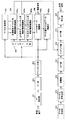
図16は、本実施の形態に係る無線基地局装置20が有するベースバンド信号処理部204及び一部の上位レイヤの機能ブロック図であり、主にベースバンド信号処理部204の送信処理の機能ブロックを示している。図16には、最大M個(CC#0〜CC#M)のコンポーネントキャリア数に対応可能な基地局構成が例示されている。無線基地局装置20の配下となるユーザ端末10に対する送信データが上位局装置30から無線基地局装置20に対して転送される。
FIG. 16 is a functional block diagram of the baseband
制御情報生成部300は、上位レイヤシグナリング(例えばRRCシグナリング)する上位制御情報をユーザ単位で生成する。また、上位制御情報は、予め拡張PDCCH(FDM型PDCCH)をマッピングできるリソースブロック(PRB位置)を含むことができる。
The control
データ生成部301は、上位局装置30から転送された送信データをユーザ別にユーザデータとして出力する。コンポーネントキャリア選択部302は、ユーザ端末10との無線通信に使用されるコンポーネントキャリアをユーザ毎に選択する。
The
スケジューリング部310は、システム帯域全体の通信品質に応じて、配下のユーザ端末10に対するコンポーネントキャリアの割当てを制御する。また、スケジューリング部310は、各コンポーネントキャリアCC#1−CC#Mにおけるリソースの割り当てを制御している。LTE端末ユーザとLTE−A端末ユーザとを区別してスケジューリングを行う。スケジューリング部310は、上位局装置30から送信データ及び再送指示が入力されると共に、上りリンクの信号を測定した受信部からチャネル推定値やリソースブロックのCQIが入力される。
The
また、スケジューリング部310は、入力された再送指示、チャネル推定値及びCQIを参照しながら、上下制御情報及び上下共有チャネル信号のスケジューリングを行う。移動通信における伝搬路は、周波数選択性フェージングにより周波数毎に変動が異なる。そこで、スケジューリング部310は、各ユーザ端末10へのユーザデータについて、サブフレーム毎に通信品質の良好なリソースブロック(マッピング位置)を指示する(適応周波数スケジューリングと呼ばれる)。適応周波数スケジューリングでは、各リソースブロックに対して伝搬路品質の良好なユーザ端末10を選択する。そのため、スケジューリング部310は、各ユーザ端末10からフィードバックされるリソースブロック毎のCQIを用いてリソースブロック(マッピング位置)を指示する。
In addition, the
同様に、スケジューリング部310は、適応周波数スケジューリングによって拡張PDCCHで送信される制御情報等について、サブフレーム毎に通信品質の良好なリソースブロック(マッピング位置)を指示することができる。このため、スケジューリング部310は、各ユーザ端末10からフィードバックされるリソースブロック毎のCQIを用いてリソースブロック(マッピング位置)を指示することができる。
Similarly,
また、スケジューリング部310は、ユーザ端末10との間の伝搬路状況に応じてアグリゲーション数を制御する。既存のPDCCHの場合にはCCEアグリゲーション数、拡張PDCCHの場合にはeCCEアグリゲーション数を制御する。セル端ユーザに対してはCCEアグリゲーション数及びeCCEアグリゲーション数を上げることになる。また、割り当てたリソースブロックで所定のブロック誤り率を満たすMCS(符号化率、変調方式)を決定する。スケジューリング部310が決定したMCS(符号化率、変調方式)を満足するパラメータがチャネル符号化部303、308、312、変調部304、309、313に設定される。
In addition, the
なお、既存のPDCCHの場合、共通サーチスペースのCCEアグリゲーション数としては、「4」、「8」がサポートされ、UE固有サーチスペースのCCEアグリゲーション数としては、「1」、「2」、「4」、「8」がサポートされる。また、拡張PDCCHの場合、共通サーチスペースのeCCEアグリゲーション数としては、「4」、「8」がサポートされ、UE固有サーチスペースのeCCEアグリゲーション数としては、「1」、「2」、「4」、「8」がサポートされる。 In the case of the existing PDCCH, “4” and “8” are supported as the number of CCE aggregations in the common search space, and “1”, “2”, and “4” as the number of CCE aggregations in the UE-specific search space. ”,“ 8 ”are supported. Also, in the case of the extended PDCCH, “4” and “8” are supported as the number of eCCE aggregations in the common search space, and “1”, “2”, and “4” as the number of eCCE aggregations in the UE-specific search space. , "8" is supported.
ベースバンド信号処理部204は、1コンポーネントキャリア内での最大ユーザ多重数Nに対応したチャネル符号化部303、変調部304、マッピング部305を備えている。チャネル符号化部303は、データ生成部301から出力されるユーザデータ(一部の上位制御信号を含む)で構成される下り共有データチャネル(PDSCH)を、ユーザ毎にチャネル符号化する。変調部304は、チャネル符号化されたユーザデータをユーザ毎に変調する。マッピング部305は、変調されたユーザデータを無線リソースにマッピングする。
The baseband
また、ベースバンド信号処理部204は、ユーザ固有の下り制御情報である下り共有データチャネル用制御情報を生成する下り制御情報生成部(生成部)306と、ユーザ共通の下り制御情報である下り共通制御チャネル用制御情報を生成する下り共通チャネル用制御情報生成部307とを備えている。
Further, the baseband
下り制御情報生成部306は、下り共有データチャネル(PDSCH)を制御するための下り共有データチャネル用制御情報(DL assignment等)を生成する。当該下り共有データチャネル用制御情報は、ユーザ毎に生成される。
The downlink control
ベースバンド信号処理部204は、1コンポーネントキャリア内での最大ユーザ多重数Nに対応したチャネル符号化部308、変調部309を備えている。チャネル符号化部308は、下り制御情報生成部306及び下り共通チャネル用制御情報生成部307で生成される制御情報をユーザ毎にチャネル符号化する。変調部309は、チャネル符号化された下り制御情報を変調する。
The baseband
また、ベースバンド信号処理部204は、上り制御情報生成部(生成部)311と、チャネル符号化部312と、変調部313とを備える。上り制御情報生成部311は、上り共有データチャネル(PUSCH)を制御するための上り共有データチャネル用制御情報(UL Grant等)を生成する。当該上り共有データチャネル用制御情報は、ユーザ毎に生成される。
The baseband
上記変調部309、313でユーザ毎に変調された制御信号は制御チャネル多重部314で多重される。既存PDCCH用の下り制御信号は、サブフレームの先頭の1〜3OFDMシンボルに多重され、インタリーブ部315でインタリーブされる。一方、拡張PDCCH用の下り制御信号は、所定のOFDMシンボル数より後のリソース領域において下り共有データチャネル信号と周波数分割多重されて、マッピング部319でリソースブロック(PRB)にマッピングされる。この場合、マッピング部319は、スケジューリング部310からの指示に基づき、上記した図5〜7、9〜12を用いて説明した方法を適用してマッピングする。
The control signals modulated for each user by the
マッピング部319は、拡張PDCCHにおける共通サーチスペースとUE固有サーチスペースとを、システム帯域を構成する所定の周波数領域単位(PRB又はRBG)で分離してマッピングする。具体的には、マッピング部319は、拡張PDCCHにおける共通サーチスペースがシステム帯域内に分散されるように、共通サーチスペースを不連続の複数の周波数領域単位(PRB又はRBG)にマッピングする。また、マッピング部319は、拡張PDCCHにおけるUE固有サーチスペースがシステム帯域内に分散されるように不連続複数の周波数領域単位(PRB又はRBG)にマッピングする。一方で、マッピング部319は、UE固有サーチスペースを構成する複数の周波数領域単位のうち、特定のユーザ端末UEの最も受信品質の良い周波数領域単位に、当該特定のユーザ端末UE用の固有制御情報を局所化してマッピングする。また、受信品質が利用できない場合は、分散マッピングを適用してもよい。
The
また、マッピング部319は、共通サーチスペースがマッピングされた複数の周波数領域単位(PRB又はRBG)の各々を複数のeCCEを含むように構成するとともに、各eCCEを分割し、分割されたeCCE同士を異なる周波数領域単位(PRB又はRBG)に分散して配置する。
In addition, the
ここで、共通サーチスペースがマッピングされた複数の周波数領域単位(PRB又はRBG)に含まれる各eCCEには周波数方向に沿ってインデックス番号が付され、分割されたeCCE同士には同じインデックス番号が付される。マッピング部319は、同じインデックス番号が付されたeCCE同士を周波数方向に並んだ異なる仮想周波数領域単位(VPRB又はVRBG)に配置した後、複数の仮想周波数領域単位(VPRB又はVRBG)をインタリーブする。これにより、同じインデックス番号が付されたeCCE同士の周波数間隔が拡大するため、周波数ダイバーシチ効果を効果的に得ることが可能となる。
Here, each eCCE included in a plurality of frequency domain units (PRB or RBG) to which the common search space is mapped is assigned an index number along the frequency direction, and the divided eCCEs are assigned the same index number. Is done. The
また、マッピング部319は、マクロ基地局B1とピコ基地局B2との間で、それぞれの共通サーチスペースを共通の周波数領域単位(PRB又はRBG)にマッピングする一方、それぞれの共通サーチスペースを異なるeCCEに割り当ててもよい。かかる場合、例えば、マクロ基地局B1に対しては、所定の周波数方向から連続するインデックス番号が付された複数のeCCE(図9では、eCCE#0〜#15)が割り当てられ、ピコ基地局B2に対しては、残りの連続するインデックス番号が付された複数のeCCE(図9では、eCCE#16〜#31)が割り当てられる。
Further, the
また、マッピング部319は、マクロ基地局B1とピコ基地局B2との間で、それぞれの共通サーチスペースを異なる周波数領域単位(PRB又はRBG)に割り当ててもよい。
Moreover, the
参照信号生成部318は、チャネル推定、シンボル同期、CQI測定、モビリティ測定等の様々な目的に使用されるセル固有参照信号(CRS:Cell-specific Reference Signal)を生成する。また、参照信号生成部318は、ユーザ個別の下りリンク復調用参照信号であるDM−RSを生成する。DM−RSは、ユーザデータの復調だけでなく、拡張PDCCHで送信される下り制御情報の復調に用いられる。
The reference
また、複数のアンテナ毎に、サブキャリアにマッピングされた送信データ及びユーザ個別の復調用参照信号(DM−RS)の位相及び/又は振幅を制御(シフト)するプリコーディングウエイト乗算部を有していてもよい。プリコーディングウエイト乗算部により、位相及び/又は振幅シフトされた送信データ及びユーザ個別の復調用参照信号(DM−RS)は、IFFT部316に出力される。 Each of the plurality of antennas includes a precoding weight multiplication unit that controls (shifts) the phase and / or amplitude of transmission data mapped to subcarriers and a demodulation reference signal (DM-RS) for each user. May be. The transmission data and the user-specific demodulation reference signal (DM-RS) shifted in phase and / or amplitude by the precoding weight multiplication unit are output to the IFFT unit 316.
IFFT部316には、インタリーブ部315及びマッピング部319から制御信号が入力され、マッピング部305からユーザデータが入力され、参照信号生成部318から参照信号が入力される。IFFT部316は、下りチャネル信号を逆高速フーリエ変換して周波数領域の信号から時系列の信号に変換する。サイクリックプレフィックス挿入部317は、下りチャネル信号の時系列信号にサイクリックプレフィックスを挿入する。なお、サイクリックプレフィックスは、マルチパス伝搬遅延の差を吸収するためのガードインターバルとして機能する。サイクリックプレフィックスが付加された送信データは、送受信部203に送出される。
The IFFT unit 316 receives control signals from the
図17は、ユーザ端末10が有するベースバンド信号処理部104の機能ブロック図であり、LTE−AをサポートするLTE−A端末の機能ブロックを示している。まず、ユーザ端末10の下りリンク構成について説明する。
FIG. 17 is a functional block diagram of the baseband
無線基地局装置20から受信データとして受信された下りリンク信号は、CP除去部401でCPが除去される。CPが除去された下りリンク信号は、FFT部402へ入力される。FFT部402は、下りリンク信号を高速フーリエ変換(FFT:Fast Fourier Transform)して時間領域の信号から周波数領域の信号に変換し、デマッピング部403へ入力する。デマッピング部403は、下りリンク信号をデマッピングし、下りリンク信号から複数の制御情報が多重された多重制御情報、ユーザデータ、上位制御情報を取り出す。なお、デマッピング部403によるデマッピング処理は、アプリケーション部105から入力される上位制御情報に基づいて行われる。デマッピング部403から出力された多重制御情報は、デインタリーブ部404でデインタリーブされる。
The
また、ベースバンド信号処理部104は、制御情報を復調する制御情報復調部405、下り共有データを復調するデータ復調部406及びチャネル推定部407を備えている。制御情報復調部405は、多重制御情報から下り共通制御チャネル用制御情報を復調する共通制御チャネル用制御情報復調部(復調部)405aと、多重制御情報から上り共有データチャネル用制御情報を復調する上り共有データチャネル用制御情報復調部(復調部)405bと、多重制御情報から下り共有データチャネル用制御情報を復調する下り共有データチャネル用制御情報復調部405cとを備えている。データ復調部406は、ユーザデータ及び上位制御信号を復調する下り共有データ復調部406aと、下り共通チャネルデータを復調する下り共通チャネルデータ復調部406bとを備えている。
The baseband
共通制御チャネル用制御情報復調部405aは、下り制御チャネル(PDCCH)及び拡張下り制御チャネル(拡張PDCCH)の共通サーチスペースのブラインドデコーディング処理、復調処理、チャネル復号処理などによりユーザ共通の制御情報である共通制御チャネル用制御情報(共通制御情報)を取り出す。共通制御チャネル用制御情報は、下りリンクのチャネル品質情報(CQI)を含んでおり、マッピング部415に入力され、無線基地局装置20への送信データの一部としてマッピングされる。既存のPDCCHの場合、共通サーチスペースとしてシグナリングされた複数のCCE候補について、ブラインドデコーディング処理が行なわれる。また、拡張PDCCHの場合、共通サーチスペースとしてシグナリングされた複数のeCCE候補について、ブラインドデコーディング処理が行なわれる。
The
上り共有データチャネル用制御情報復調部405bは、下り制御チャネル(PDCCH)及び拡張下り制御チャネル(拡張PDCCH)のUE固有サーチスペースのブラインドデコーディング処理、復調処理、チャネル復号処理などにより上り共有データチャネル用制御情報(固有制御情報)(例えば、UL Grant)を取り出す。既存のPDCCHの場合には、UE固有サーチスペースとしてシグナリングされた複数のCCE候補について、ブラインドデコーディング処理が行われる。また、拡張PDCCHの場合、UE固有サーチスペースとしてシグナリングされた複数のeCCE候補について、ブラインドデコーディング処理が行われる。復調された上り共有データチャネル用制御情報は、マッピング部415に入力されて、上り共有データチャネル(PUSCH)の制御に使用される。
The uplink shared data channel
下り共有データチャネル用制御情報復調部405cは、下り制御チャネル(PDCCH)及び拡張下り制御チャネル(拡張PDCCH)のUE固有サーチスペースのブラインドデコーディング処理、復調処理、チャネル復号処理などにより下り共有データチャネル用制御情報(固有制御情報)(例えば、DL assignment)を取り出す。既存のPDCCHの場合には、UE固有サーチスペースとしてシグナリングされた複数のCCE候補について、ブラインドデコーディング処理が行われる。また、拡張PDCCHの場合、UE固有サーチスペースとしてシグナリングされた複数のeCCE候補について、ブラインドデコーディング処理が行われる。復調された下り共有データチャネル用制御情報は、下り共有データ復調部406aへ入力されて、下り共有データチャネル(PDSCH)の制御に使用され、下り共有データ復調部406aに入力される。
The downlink shared data channel control
下り共有データ復調部406aは、下り共有データチャネル用制御情報復調部405cから入力された下り共有データチャネル用制御情報に基づいて、ユーザデータや上位制御情報を取得する。上位制御情報に含まれる拡張PDCCHがマッピング可能なPRB位置(或いはRBG位置)は、下り共有データチャネル用制御情報復調部405cに出力される。下り共通チャネルデータ復調部406bは、上り共有データチャネル用制御情報復調部405bから入力された上り共有データチャネル用制御情報に基づいて、下り共通チャネルデータを復調する。
The downlink shared
チャネル推定部407は、ユーザ固有の参照信号(DM−RS)、またはセル固有の参照信号(CRS)を用いてチャネル推定する。既存PDCCHを復調する場合には、セル固有の参照信号を用いてチャネル推定する。一方、拡張PDCCH及びユーザデータを復調する場合には、DM−RSやCRSを用いてチャネル推定する。推定されたチャネル変動を、共通制御チャネル用制御情報復調部405a、上り共有データチャネル用制御情報復調部405b、下り共有データチャネル用制御情報復調部405c及び下り共有データ復調部406aに出力する。これらの復調部においては、推定されたチャネル変動及び復調用の参照信号を用いて復調処理を行う。
The
また、拡張PDCCHにおいて同一PRB(又は同一RBG)内に異なるユーザの複数のeCCEが周波数分割多重等される場合、PRB(又はRBG)内の周波数リソースの番号に括りつけられたDM−RSのアンテナポートを用いて制御情報が復調される。この場合、ユーザ毎(eCCE毎)に異なるDM−RSの送信ウェイトにより、同一PRB(又は同一RBG)内のDM−RSをユーザ毎に区別している。一方、送信ダイバーシチを適用する場合には、DM−RSのアンテナポートを1PRB(又は1RBG)内に割当てられるユーザ端末で共通化して設定することができる。 In addition, when a plurality of eCCEs of different users are frequency-division multiplexed in the same PRB (or the same RBG) in the extended PDCCH, DM-RS antennas bundled with frequency resource numbers in the PRB (or RBG) Control information is demodulated using the port. In this case, DM-RSs in the same PRB (or the same RBG) are distinguished for each user by DM-RS transmission weights that differ for each user (each eCCE). On the other hand, when transmitting diversity is applied, DM-RS antenna ports can be shared and set by user terminals allocated within 1 PRB (or 1 RBG).
ベースバンド信号処理部104は、送信処理系の機能ブロックとして、データ生成部411、チャネル符号化部412、変調部413、DFT部414、マッピング部415、IFFT部416、CP挿入部417を備えている。データ生成部411は、アプリケーション部105から入力されるビットデータから送信データを生成する。チャネル符号化部412は、送信データに対して誤り訂正等のチャネル符号化処理を施し、変調部413はチャネル符号化された送信データをQPSK等で変調する。
The baseband
DFT部414は、変調された送信データを離散フーリエ変換する。マッピング部415は、DFT後のデータシンボルの各周波数成分を、無線基地局装置20に指示されたサブキャリア位置へマッピングする。IFFT部416は、システム帯域に相当する入力データを逆高速フーリエ変換して時系列データに変換し、CP挿入部417は時系列データに対してデータ区切りでサイクリックプレフィックスを挿入する。
The DFT unit 414 performs discrete Fourier transform on the modulated transmission data. Mapping section 415 maps each frequency component of the data symbol after DFT to a subcarrier position designated by radio
以上のように、本実施の形態に係る無線基地局装置20によれば、共通サーチスペースとUE固有サーチスペースとを、所定の周波数領域単位(PRB又はRBG)で分離してマッピングする。特に、無線基地局装置20は、共通サーチスペースを、システム帯域内に分散されるように不連続の複数の周波数領域単位(RB又はRBG)にマッピングする。このため、周波数ダイバーシチ効果により、セル内の全ユーザ端末UEが安定して共通制御情報を復号可能となる。また、無線基地局装置20は、UE固有サーチスペースを、システム帯域帯域内に分散されるように不連続の複数の周波数領域単位に(PRB又はRBG)にマッピングする。一方で、無線基地局装置20は、UE固有サーチスペースを構成する複数の周波数領域単位のうち、特定のユーザ端末UEの最も受信品質の良い周波数領域単位に、当該手奥鄭のユーザ端末UE用の固有制御情報を局所化してマッピングする。このため、特定のユーザ端末UEはより受信品質の良い周波数領域単位(PRB又はRBG)で固有制御情報を復号可能となる。また、受信品質が利用できない場合は、分散マッピングを適用してもよい。
As described above, according to radio
以上、上述の実施形態を用いて本発明について詳細に説明したが、当業者にとっては、本発明が本明細書中に説明した実施形態に限定されるものではないということは明らかである。本発明は、特許請求の範囲の記載により定まる本発明の趣旨及び範囲を逸脱することなく修正及び変更態様として実施することができる。従って、本明細書の記載は、例示説明を目的とするものであり、本発明に対して何ら制限的な意味を有するものではない。 Although the present invention has been described in detail using the above-described embodiments, it is obvious to those skilled in the art that the present invention is not limited to the embodiments described in this specification. The present invention can be implemented as modified and changed modes without departing from the spirit and scope of the present invention defined by the description of the scope of claims. Therefore, the description of the present specification is for illustrative purposes and does not have any limiting meaning to the present invention.
1 無線通信システム
10 ユーザ端末
20 無線基地局装置
101 送受信アンテナ
103 送受信部(受信部)
104 ベースバンド信号処理部
201 送受信アンテナ
203 送受信部(送信部)
204 ベースバンド信号処理部
300 制御情報生成部
301 データ生成部
305 マッピング部
306 下り制御情報生成部
307 下り共通チャネル用制御情報生成部
310 スケジューリング部
311 上り制御情報生成部
314 制御チャネル多重部
315 インタリーブ部
318 参照信号生成部
319 マッピング部
403 デマッピング部
404 デインタリーブ部
405 制御情報復調部(復号部)
405a 共通制御チャネル用制御情報復調部
405b 上り共有データチャネル用制御情報復調部
405c 下り共有データチャネル用制御情報復調部
406 データ復調部
406a 下り共有データ復調部
406b 下り共通チャネルデータ復調部
407 チャネル推定部
DESCRIPTION OF
104 Baseband
204 Baseband
405a Common control channel control
Claims (5)
前記拡張下り制御チャネルの共通サーチスペースをブラインドデコーディングして、前記共通サーチスペース内の拡張制御チャネル要素(eCCE)に配置される共通制御情報を検出する復号部と、を具備し、
前記共通サーチスペースは、前記ユーザ端末がサポートする周波数帯域全体に分散された複数の物理リソースブロック(PRB)を含んで構成され、
前記共通制御情報が配置される前記eCCEは、該複数のPRBの少なくとも2つに分散マッピングされ、
前記復号部は、前記拡張下り制御チャネルのユーザ端末固有サーチスペースをブラインドデコーディングして、前記ユーザ端末固有サーチスペース内のeCCEに配置されるユーザ端末固有の固有制御情報を検出し、
前記ユーザ端末固有サーチスペースは、前記共通サーチスペースを構成する前記複数のPRBとは異なる複数のPRBで構成されることを特徴とするユーザ端末。 A receiver for receiving the extended downlink control channel;
A decoding unit that performs blind decoding on a common search space of the extended downlink control channel and detects common control information arranged in an extended control channel element (eCCE) in the common search space;
The common search space includes a plurality of physical resource blocks (PRBs) distributed over the entire frequency band supported by the user terminal,
The eCCE in which the common control information is arranged is distributedly mapped to at least two of the plurality of PRBs ,
The decoding unit performs blind decoding on a user terminal specific search space of the extended downlink control channel to detect user terminal specific specific control information arranged in an eCCE in the user terminal specific search space,
It said user terminal-specific search space, the user terminal characterized by Rukoto consists of different PRB from said plurality of PRB constituting the common search space.
前記固有制御情報が配置される前記eCCEは、前記ユーザ端末固有サーチスペースを構成する前記複数のPRBのうちの一つに局所マッピングされる、又は、前記ユーザ端末固有サーチスペースを構成する前記複数のPRBの少なくとも2つに分散マッピングされることを特徴とする請求項1に記載のユーザ端末。 The plurality of PRB constituting the front SL user terminal-specific search space, it is distributed throughout the frequency band,
The eCCE in which the unique control information is arranged is locally mapped to one of the plurality of PRBs constituting the user terminal specific search space , or the plurality of pieces constituting the user terminal specific search space The user terminal according to claim 1, wherein the user terminal is distributedly mapped to at least two of the PRBs.
前記拡張下り制御チャネルをユーザ端末に送信する送信部と、を具備し、
前記共通サーチスペースは、前記ユーザ端末がサポートする周波数帯域全体に分散された複数の物理リソースブロック(PRB)を含んで構成され、
前記マッピング部は、前記共通制御情報が配置される前記eCCEを該複数のPRBの少なくとも2つに分散マッピングし、
前記マッピング部は、前記拡張下り制御チャネルのユーザ端末固有サーチスペース内のeCCEにユーザ端末固有の固有制御情報を配置し、
前記ユーザ端末固有サーチスペースは、前記共通サーチスペースを構成する前記複数のPRBとは異なる複数のPRBで構成されることを特徴とする無線基地局装置。 A mapping unit that arranges common control information in an extended control channel element (eCCE) in a common search space of the extended downlink control channel;
A transmission unit for transmitting the extended downlink control channel to a user terminal,
The common search space includes a plurality of physical resource blocks (PRBs) distributed over the entire frequency band supported by the user terminal,
The mapping unit performs distributed mapping of the eCCE in which the common control information is arranged to at least two of the plurality of PRBs ,
The mapping unit arranges user terminal specific unique control information in eCCE in the user terminal specific search space of the extended downlink control channel,
The radio base station apparatus, wherein the user terminal specific search space includes a plurality of PRBs different from the plurality of PRBs constituting the common search space .
前記ユーザ端末が、前記共通サーチスペースをブラインドデコーディングして、前記共通サーチスペース内の拡張制御チャネル要素(eCCE)に配置される共通制御情報を検出するステップと、を有し、
前記共通サーチスペースは、前記ユーザ端末がサポートする周波数帯域全体に分散された複数の物理リソースブロック(PRB)を含んで構成され、
前記共通制御情報が配置される前記eCCEは、該複数のPRBの少なくとも2つに分散マッピングされ、
前記検出するステップにおいて、前記ユーザ端末は、前記拡張下り制御チャネルのユーザ端末固有サーチスペースをブラインドデコーディングして、前記ユーザ端末固有サーチスペース内のeCCEに配置されるユーザ端末固有の固有制御情報を検出し、
前記ユーザ端末固有サーチスペースは、前記共通サーチスペースを構成する前記複数のPRBとは異なる複数のPRBで構成されることを特徴とする無線通信方法。 A user terminal receiving an enhanced downlink control channel;
The user terminal blind-decoding the common search space to detect common control information arranged in an extended control channel element (eCCE) in the common search space;
The common search space includes a plurality of physical resource blocks (PRBs) distributed over the entire frequency band supported by the user terminal,
The eCCE in which the common control information is arranged is distributedly mapped to at least two of the plurality of PRBs ,
In the detecting step, the user terminal blind-decodes the user terminal specific search space of the extended downlink control channel, and the user terminal specific control information arranged in the eCCE in the user terminal specific search space. Detect
It said user terminal-specific search space, radio communication method, wherein Rukoto consists of different PRB from said plurality of PRB constituting the common search space.
Priority Applications (5)
| Application Number | Priority Date | Filing Date | Title |
|---|---|---|---|
| JP2012017314A JP6219018B2 (en) | 2012-01-30 | 2012-01-30 | Radio base station apparatus, user terminal, radio communication system, and radio communication method |
| US14/375,212 US20150016370A1 (en) | 2012-01-30 | 2013-01-30 | Radio base station apparatus, user terminal, radio communication system and radio communication method |
| EP13743834.7A EP2811799A4 (en) | 2012-01-30 | 2013-01-30 | Wireless base station device, user terminal, wireless communication system, and wireless communication method |
| CN201380007240.8A CN104094659A (en) | 2012-01-30 | 2013-01-30 | Wireless base station device, user terminal, wireless communication system, and wireless communication method |
| PCT/JP2013/052065 WO2013115260A1 (en) | 2012-01-30 | 2013-01-30 | Wireless base station device, user terminal, wireless communication system, and wireless communication method |
Applications Claiming Priority (1)
| Application Number | Priority Date | Filing Date | Title |
|---|---|---|---|
| JP2012017314A JP6219018B2 (en) | 2012-01-30 | 2012-01-30 | Radio base station apparatus, user terminal, radio communication system, and radio communication method |
Publications (2)
| Publication Number | Publication Date |
|---|---|
| JP2013157822A JP2013157822A (en) | 2013-08-15 |
| JP6219018B2 true JP6219018B2 (en) | 2017-10-25 |
Family
ID=48905292
Family Applications (1)
| Application Number | Title | Priority Date | Filing Date |
|---|---|---|---|
| JP2012017314A Expired - Fee Related JP6219018B2 (en) | 2012-01-30 | 2012-01-30 | Radio base station apparatus, user terminal, radio communication system, and radio communication method |
Country Status (5)
| Country | Link |
|---|---|
| US (1) | US20150016370A1 (en) |
| EP (1) | EP2811799A4 (en) |
| JP (1) | JP6219018B2 (en) |
| CN (1) | CN104094659A (en) |
| WO (1) | WO2013115260A1 (en) |
Families Citing this family (32)
| Publication number | Priority date | Publication date | Assignee | Title |
|---|---|---|---|---|
| CN104221437B (en) | 2012-03-16 | 2018-04-13 | 联发科技股份有限公司 | The physical arrangement and reference signal for strengthening physical downlink control channel in OFDM/OFDMA systems utilize |
| US9445409B2 (en) | 2012-03-21 | 2016-09-13 | Mediatek, Inc. | Method for search space configuration of enhanced physical downlink control channel |
| US9756645B2 (en) * | 2014-03-14 | 2017-09-05 | Intel IP Corporation | ENB, UE and method for physical resource block allocation in MTC UE |
| WO2015139773A1 (en) * | 2014-03-21 | 2015-09-24 | Nokia Solutions And Networks Oy | Resource release for proximity-based communications |
| WO2016107189A1 (en) * | 2014-12-31 | 2016-07-07 | 华为技术有限公司 | Communication device and method therefor |
| CN107548539B (en) * | 2015-05-21 | 2022-02-08 | 英特尔公司 | Physical downlink control channel for fifth generation networks |
| US10104658B2 (en) | 2015-06-12 | 2018-10-16 | Asustek Computer Inc. | Method and apparatus for delivery of control signaling in a wireless communication system |
| EP3337262A4 (en) * | 2015-08-11 | 2019-03-13 | Mitsubishi Electric Corporation | Communication system |
| EP3131223B1 (en) * | 2015-08-11 | 2018-06-27 | Panasonic Intellectual Property Corporation of America | Improved blind decoding of (e)pdcch for partial subframes |
| JP6076424B1 (en) * | 2015-08-13 | 2017-02-08 | 株式会社Nttドコモ | User terminal, radio base station, and radio communication method |
| JP6669278B2 (en) * | 2016-05-13 | 2020-03-18 | 富士通株式会社 | Resource mapping method, apparatus and communication system |
| JP6959235B2 (en) * | 2016-07-29 | 2021-11-02 | 株式会社Nttドコモ | Terminals, wireless communication methods, base stations and systems |
| JP7103945B2 (en) * | 2016-09-29 | 2022-07-20 | 株式会社Nttドコモ | Terminal and wireless communication method |
| EP3515144A4 (en) * | 2016-09-29 | 2019-09-11 | Ntt Docomo, Inc. | User terminal and wireless communication method |
| US11825482B2 (en) * | 2016-10-03 | 2023-11-21 | Qualcomm Incorporated | Techniques for improved control channels |
| KR102479280B1 (en) * | 2016-11-01 | 2022-12-20 | 가부시키가이샤 엔티티 도코모 | User terminal and wireless communication method |
| CN110268752B (en) * | 2016-12-14 | 2022-12-06 | 株式会社Ntt都科摩 | User terminal and wireless communication method |
| EP3565335B1 (en) * | 2016-12-27 | 2021-08-18 | NTT DoCoMo, Inc. | User terminal and wireless communications method |
| EP3603291B1 (en) * | 2017-03-24 | 2024-02-14 | Motorola Mobility LLC | Method and apparatus for determining a user data resource assignment |
| US10278168B2 (en) | 2017-05-04 | 2019-04-30 | At&T Intellectual Property I, L.P. | Multi-stage segmented downlink control information with reduced overhead |
| WO2019028767A1 (en) * | 2017-08-10 | 2019-02-14 | 富士通株式会社 | Method and device for allocating frequency domain resources, method and device for receiving frequency domain resources, and communication system |
| WO2019033392A1 (en) * | 2017-08-18 | 2019-02-21 | Oppo广东移动通信有限公司 | Signal transmission method, terminal device and network device |
| CN109474401B (en) * | 2017-09-08 | 2021-09-21 | 北京紫光展锐通信技术有限公司 | Method, device, base station and user equipment for issuing and monitoring preemption indication |
| CN110447254B (en) * | 2017-09-11 | 2022-10-21 | 联发科技股份有限公司 | Method for transmitting beam fault recovery request and user equipment thereof |
| US11356231B2 (en) | 2017-09-29 | 2022-06-07 | Telefonaktiebolaget Lm Ericsson (Publ) | Short control channel element (SCCE) to short resource element groups (SREG) mapping for short physical downlink control channel (SPDCCH) |
| CN108496317B (en) | 2017-11-02 | 2021-11-16 | 北京小米移动软件有限公司 | Method and device for searching public resource set of residual key system information |
| JP7320841B2 (en) * | 2017-11-17 | 2023-08-04 | 株式会社Nttドコモ | Terminal, wireless communication method, base station and system |
| WO2019104672A1 (en) | 2017-11-30 | 2019-06-06 | 北京小米移动软件有限公司 | Information indication method and apparatus, base station, and user equipment |
| KR101954433B1 (en) | 2018-01-11 | 2019-03-05 | 엘지전자 주식회사 | A method of receiving a downlink signal for a terminal in a wireless communication system and a terminal using the same |
| US10448388B2 (en) * | 2018-01-11 | 2019-10-15 | Lg Electronics Inc. | Method for receiving downlink signal in wireless communication system and terminal using the same |
| CN111801971A (en) * | 2018-01-11 | 2020-10-20 | 株式会社Ntt都科摩 | User terminal and wireless communication method |
| CN113396619A (en) * | 2018-12-11 | 2021-09-14 | 株式会社Ntt都科摩 | User terminal and wireless communication method |
Family Cites Families (13)
| Publication number | Priority date | Publication date | Assignee | Title |
|---|---|---|---|---|
| RU2491780C2 (en) * | 2008-11-04 | 2013-08-27 | Рокстар Бидко, Лп | Method of wireless communication and mobile station and base station it applies |
| JP5162416B2 (en) * | 2008-11-07 | 2013-03-13 | 株式会社エヌ・ティ・ティ・ドコモ | Wireless base station |
| US20100172308A1 (en) * | 2009-01-07 | 2010-07-08 | Samsung Electronics Co., Ltd. | System and method for downlink physical indicator channel mapping with asymmetric carrier aggregation |
| US8995358B2 (en) * | 2009-04-30 | 2015-03-31 | Qualcomm Incorporated | False detection reduction during multi-carrier operation |
| US8780853B2 (en) * | 2009-11-06 | 2014-07-15 | Kyocera Corporation | Control channel management |
| JP2011142532A (en) * | 2010-01-08 | 2011-07-21 | Sharp Corp | Wireless communication system, base station apparatus, mobile station device, wireless communication method, and integrated circuit |
| JP5763753B2 (en) * | 2010-05-17 | 2015-08-12 | エルジー エレクトロニクス インコーポレイティド | Downlink control information transmission / reception method and apparatus for repeater |
| US20130003604A1 (en) * | 2011-06-30 | 2013-01-03 | Research In Motion Limited | Method and Apparatus for Enhancing Downlink Control Information Transmission |
| US10079658B2 (en) * | 2011-11-04 | 2018-09-18 | Qualcomm Incorporated | Search space design for e-PDCCH in wireless communication networks |
| JP2013098946A (en) * | 2011-11-07 | 2013-05-20 | Sharp Corp | Terminal, base station, communication system and communication method |
| KR102094050B1 (en) * | 2012-01-27 | 2020-03-27 | 인터디지탈 패튼 홀딩스, 인크 | Systems and/or methods for providing epdcch in a multiple carrier based and/or quasi-collated network |
| US9445409B2 (en) * | 2012-03-21 | 2016-09-13 | Mediatek, Inc. | Method for search space configuration of enhanced physical downlink control channel |
| US9166718B2 (en) * | 2012-05-11 | 2015-10-20 | Intel Corporation | Downlink control indication for a stand-alone new carrier type (NCT) |
-
2012
- 2012-01-30 JP JP2012017314A patent/JP6219018B2/en not_active Expired - Fee Related
-
2013
- 2013-01-30 EP EP13743834.7A patent/EP2811799A4/en not_active Withdrawn
- 2013-01-30 WO PCT/JP2013/052065 patent/WO2013115260A1/en active Application Filing
- 2013-01-30 CN CN201380007240.8A patent/CN104094659A/en active Pending
- 2013-01-30 US US14/375,212 patent/US20150016370A1/en not_active Abandoned
Also Published As
| Publication number | Publication date |
|---|---|
| CN104094659A (en) | 2014-10-08 |
| EP2811799A1 (en) | 2014-12-10 |
| EP2811799A4 (en) | 2015-09-02 |
| US20150016370A1 (en) | 2015-01-15 |
| WO2013115260A1 (en) | 2013-08-08 |
| JP2013157822A (en) | 2013-08-15 |
Similar Documents
| Publication | Publication Date | Title |
|---|---|---|
| JP6219018B2 (en) | Radio base station apparatus, user terminal, radio communication system, and radio communication method | |
| JP5487229B2 (en) | Radio base station apparatus, user terminal, radio communication system, and radio communication method | |
| JP5554799B2 (en) | Radio base station apparatus, user terminal, radio communication system, and radio communication method | |
| JP5771177B2 (en) | Wireless base station, user terminal, wireless communication system, and wireless communication method | |
| JP5726819B2 (en) | Decoding method, radio base station, user terminal, and radio communication system | |
| JP5809103B2 (en) | Wireless base station, user terminal, wireless communication system, and wireless communication method | |
| JP5829987B2 (en) | Wireless communication method, wireless communication system, and wireless base station | |
| JP5898874B2 (en) | User terminal, radio base station apparatus, radio communication system, and radio communication method | |
| JP5616284B2 (en) | Base station apparatus, mobile terminal apparatus, communication system, and communication method | |
| WO2012150667A1 (en) | Wireless base station device, mobile terminal device, wireless communication system, and wireless communication method | |
| WO2012150687A1 (en) | User terminal, wireless base station, downlink control channel reception method, and mobile communication system | |
| JP6105693B2 (en) | Wireless communication method, wireless communication system, and wireless base station | |
| JP6068860B2 (en) | Wireless communication method, wireless base station, user terminal, and wireless communication system | |
| US9882694B2 (en) | Radio base station, user terminal, radio communication system and radio communication method | |
| JP6106725B2 (en) | Wireless base station, user terminal, wireless communication system, and wireless communication method |
Legal Events
| Date | Code | Title | Description |
|---|---|---|---|
| A621 | Written request for application examination |
Free format text: JAPANESE INTERMEDIATE CODE: A621 Effective date: 20150122 |
|
| A131 | Notification of reasons for refusal |
Free format text: JAPANESE INTERMEDIATE CODE: A131 Effective date: 20160105 |
|
| A521 | Request for written amendment filed |
Free format text: JAPANESE INTERMEDIATE CODE: A523 Effective date: 20160302 |
|
| A131 | Notification of reasons for refusal |
Free format text: JAPANESE INTERMEDIATE CODE: A131 Effective date: 20160906 |
|
| A521 | Request for written amendment filed |
Free format text: JAPANESE INTERMEDIATE CODE: A523 Effective date: 20161104 |
|
| A02 | Decision of refusal |
Free format text: JAPANESE INTERMEDIATE CODE: A02 Effective date: 20170425 |
|
| A521 | Request for written amendment filed |
Free format text: JAPANESE INTERMEDIATE CODE: A523 Effective date: 20170719 |
|
| A911 | Transfer to examiner for re-examination before appeal (zenchi) |
Free format text: JAPANESE INTERMEDIATE CODE: A911 Effective date: 20170727 |
|
| TRDD | Decision of grant or rejection written | ||
| A01 | Written decision to grant a patent or to grant a registration (utility model) |
Free format text: JAPANESE INTERMEDIATE CODE: A01 Effective date: 20170912 |
|
| A61 | First payment of annual fees (during grant procedure) |
Free format text: JAPANESE INTERMEDIATE CODE: A61 Effective date: 20170927 |
|
| R150 | Certificate of patent or registration of utility model |
Ref document number: 6219018 Country of ref document: JP Free format text: JAPANESE INTERMEDIATE CODE: R150 |
|
| LAPS | Cancellation because of no payment of annual fees |