EP2903371B1 - Station de base radio, terminal utilisateur, système et procédé de radiocommunication - Google Patents
Station de base radio, terminal utilisateur, système et procédé de radiocommunication Download PDFInfo
- Publication number
- EP2903371B1 EP2903371B1 EP13840326.6A EP13840326A EP2903371B1 EP 2903371 B1 EP2903371 B1 EP 2903371B1 EP 13840326 A EP13840326 A EP 13840326A EP 2903371 B1 EP2903371 B1 EP 2903371B1
- Authority
- EP
- European Patent Office
- Prior art keywords
- ecce
- control channel
- search space
- enhanced
- channel elements
- Prior art date
- Legal status (The legal status is an assumption and is not a legal conclusion. Google has not performed a legal analysis and makes no representation as to the accuracy of the status listed.)
- Active
Links
- 238000000034 method Methods 0.000 title claims description 50
- 238000004891 communication Methods 0.000 title claims description 37
- 238000013507 mapping Methods 0.000 claims description 97
- 230000002776 aggregation Effects 0.000 claims description 55
- 238000004220 aggregation Methods 0.000 claims description 55
- 238000010586 diagram Methods 0.000 description 32
- 230000005540 biological transmission Effects 0.000 description 31
- 238000012545 processing Methods 0.000 description 19
- 230000008569 process Effects 0.000 description 12
- 238000013459 approach Methods 0.000 description 9
- 101150070878 Ereg gene Proteins 0.000 description 5
- 230000000903 blocking effect Effects 0.000 description 5
- 238000005259 measurement Methods 0.000 description 5
- 101150071746 Pbsn gene Proteins 0.000 description 4
- 238000006243 chemical reaction Methods 0.000 description 4
- 239000013256 coordination polymer Substances 0.000 description 4
- 230000011664 signaling Effects 0.000 description 4
- 238000012937 correction Methods 0.000 description 3
- 101000741965 Homo sapiens Inactive tyrosine-protein kinase PRAG1 Proteins 0.000 description 2
- 102100038659 Inactive tyrosine-protein kinase PRAG1 Human genes 0.000 description 2
- 239000000969 carrier Substances 0.000 description 2
- 125000004122 cyclic group Chemical group 0.000 description 2
- 230000007423 decrease Effects 0.000 description 2
- 230000000694 effects Effects 0.000 description 2
- 230000008859 change Effects 0.000 description 1
- 239000012050 conventional carrier Substances 0.000 description 1
- 230000008878 coupling Effects 0.000 description 1
- 238000010168 coupling process Methods 0.000 description 1
- 238000005859 coupling reaction Methods 0.000 description 1
- 230000001934 delay Effects 0.000 description 1
- 230000007774 longterm Effects 0.000 description 1
- 238000007726 management method Methods 0.000 description 1
- 238000010295 mobile communication Methods 0.000 description 1
- 238000012986 modification Methods 0.000 description 1
- 230000004048 modification Effects 0.000 description 1
- 238000013468 resource allocation Methods 0.000 description 1
- 230000003595 spectral effect Effects 0.000 description 1
Images


Classifications
-
- H—ELECTRICITY
- H04—ELECTRIC COMMUNICATION TECHNIQUE
- H04L—TRANSMISSION OF DIGITAL INFORMATION, e.g. TELEGRAPHIC COMMUNICATION
- H04L1/00—Arrangements for detecting or preventing errors in the information received
- H04L1/004—Arrangements for detecting or preventing errors in the information received by using forward error control
- H04L1/0045—Arrangements at the receiver end
- H04L1/0046—Code rate detection or code type detection
-
- H—ELECTRICITY
- H04—ELECTRIC COMMUNICATION TECHNIQUE
- H04W—WIRELESS COMMUNICATION NETWORKS
- H04W72/00—Local resource management
- H04W72/20—Control channels or signalling for resource management
- H04W72/23—Control channels or signalling for resource management in the downlink direction of a wireless link, i.e. towards a terminal
-
- H—ELECTRICITY
- H04—ELECTRIC COMMUNICATION TECHNIQUE
- H04B—TRANSMISSION
- H04B7/00—Radio transmission systems, i.e. using radiation field
- H04B7/02—Diversity systems; Multi-antenna system, i.e. transmission or reception using multiple antennas
- H04B7/04—Diversity systems; Multi-antenna system, i.e. transmission or reception using multiple antennas using two or more spaced independent antennas
- H04B7/0413—MIMO systems
- H04B7/0452—Multi-user MIMO systems
-
- H—ELECTRICITY
- H04—ELECTRIC COMMUNICATION TECHNIQUE
- H04L—TRANSMISSION OF DIGITAL INFORMATION, e.g. TELEGRAPHIC COMMUNICATION
- H04L1/00—Arrangements for detecting or preventing errors in the information received
- H04L1/004—Arrangements for detecting or preventing errors in the information received by using forward error control
- H04L1/0072—Error control for data other than payload data, e.g. control data
-
- H—ELECTRICITY
- H04—ELECTRIC COMMUNICATION TECHNIQUE
- H04L—TRANSMISSION OF DIGITAL INFORMATION, e.g. TELEGRAPHIC COMMUNICATION
- H04L27/00—Modulated-carrier systems
- H04L27/26—Systems using multi-frequency codes
- H04L27/2601—Multicarrier modulation systems
- H04L27/2626—Arrangements specific to the transmitter only
- H04L27/2627—Modulators
- H04L27/2643—Modulators using symbol repetition, e.g. time domain realization of distributed FDMA
-
- H—ELECTRICITY
- H04—ELECTRIC COMMUNICATION TECHNIQUE
- H04L—TRANSMISSION OF DIGITAL INFORMATION, e.g. TELEGRAPHIC COMMUNICATION
- H04L5/00—Arrangements affording multiple use of the transmission path
- H04L5/003—Arrangements for allocating sub-channels of the transmission path
- H04L5/0053—Allocation of signaling, i.e. of overhead other than pilot signals
-
- H—ELECTRICITY
- H04—ELECTRIC COMMUNICATION TECHNIQUE
- H04W—WIRELESS COMMUNICATION NETWORKS
- H04W88/00—Devices specially adapted for wireless communication networks, e.g. terminals, base stations or access point devices
- H04W88/02—Terminal devices
-
- H—ELECTRICITY
- H04—ELECTRIC COMMUNICATION TECHNIQUE
- H04W—WIRELESS COMMUNICATION NETWORKS
- H04W88/00—Devices specially adapted for wireless communication networks, e.g. terminals, base stations or access point devices
- H04W88/08—Access point devices
Definitions
- the present invention relates to a radio base station, a user terminal, a radio communication system and a radio communication method in a next-generation radio communication system.
- LTE Long-term evolution
- OFDMA Orthogonal Frequency Division Multiple Access
- SC-FDMA Single Carrier Frequency Division Multiple Access
- LTE-advanced or “LTE enhancement” (hereinafter referred to as "LTE-A")
- LTE-A LTE enhancement
- MIMO Multi-Input Multi-Output
- a plurality of transmitting/receiving antennas are provided in a transmitter/receiver, so that different transmission information sequences are transmitted from different transmitting antennas at the same time.
- Non-Patent Literature 1 3GPP TR25.913 "Requirements for Evolved UTRA and Evolved UTRAN " The 3GPP document " Search space configuration for localized ePDCCH",R1-123305, Fujitsu, 13.08.2012 , discloses several prior art methods for configuring the search space of localized ePDCCH transmissions.
- MU-MIMO multiple-user MIMO
- HetNet Heterogeneous Network
- CoMP Coordinatd Multi-Point
- the present invention has been made in view of the above, and it is therefore an object of the present invention to provide a radio base station, a user terminal, a radio communication system and a radio communication method that can adequately form the search space candidates to use for the blind decoding of downlink control information when the radio resource regions for downlink control channels are expanded.
- the present invention relates to a radio base station, to a user terminal, to a radio communication system and to a corresponding radio communication method, according to the accompanying claims.
- the radio resource regions for downlink control channels are expanded, it is possible to adequately form the search space candidates to be used in the blind decoding of downlink control information.
- FIG. 1 is a diagram to show an example of a radio communication system where MU-MIMO transmission is applied.
- the system shown in FIG. 1 is structured in layers by providing small base stations (for example, RRHs (Remote Radio Heads)) having local coverage areas within the coverage area of a radio base station (for example, an eNB: eNodeB).
- RRHs Remote Radio Heads
- a radio base station for example, an eNB: eNodeB
- UE User Equipment
- UE #2 User Equipment #1 and UE #2
- data for a plurality of user terminals UE #3 and UE #4 is transmitted at the same time from a plurality of antennas of a plurality of small base stations.
- FIG. 2 is a diagram to show an example of a radio frame (for example, one subframe) where downlink MU-MIMO transmission is applied.
- a predetermined number of OFDM symbols (maximum three OFDM symbols) from the top of each subframe are secured as a radio resource region (PDCCH region) for a downlink control channel (PDCCH: Physical Downlink Control CHannel).
- PDSCH region for a downlink shared data channel (PDSCH: Physical Downlink Shared CHannel) is secured in radio resources following the predetermined number of symbols from the subframe top.
- DCI downlink control information
- the DCI includes allocation information of data for the user terminals UE in the PDSCH region, and/or the like.
- user terminal UE #2 receives the data for user terminal UE #2 that is allocated to the PDSCH region, based on the DCI for user terminal UE #2 that is allocated to the PDCCH region.
- MU-MIMO transmission it is possible to transmit data to a plurality of user terminals UE in the same time and in the same frequency. Consequently, in the PDSCH region of FIG. 2 , it may be possible to multiplex data for user terminal UE #1 and data for user terminal UE #5 over the same frequency region. Similarly, it may be also possible to multiplex data for user terminal UE #4 and data for user terminal UE #6 over the same frequency region.
- the region may be possible to expand the region to allocate the PDCCH to beyond the control region that is maximum three OFDM symbols from the top of a subframe (that is, expand the PDCCH region into the conventional PDSCH region, which is from the fourth OFDM symbol onward).
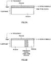
- the method of expanding the PDCCH region there are a method of time-division-multiplexing the PDSCH and the PDCCH in the conventional PDSCH region as shown in FIG. 3A (TDM approach), and a method of frequency-division-multiplexing the PDSCH and the PDCCH in the conventional PDSCH region as shown in FIG. 3B (FDM approach).
- the PDCCH is placed over the entire system band in part of the OFDM symbols from the fourth OFDM symbol onward in the subframe.
- the PDCCH is placed in part of the system band in all of the OFDM symbols from the fourth OFDM symbol onward in the subframe.
- This PDCCH frequency-division-multiplexed with the PDSCH in the FDM approach, is demodulated using a demodulation reference signal (DM-RS), which is a user-specific reference signal.
- DM-RS demodulation reference signal
- DCI that is transmitted in this PDCCH can achieve beam-forming gain, like downlink data that is transmitted in the PDSCH does, and therefore it is effective to increase the capacity of the PDCCH. In the future, it is expected that this FDM approach will gain greater importance.
- a PDCCH that is frequency-division-multiplexed with the PDSCH in the FDM approach will be referred to as an "enhanced PDCCH.”
- This enhanced PDCCH may also be referred to as an "enhanced downlink control channel (enhanced physical downlink control channel),” an "ePDCCH,” an “E-PDCCH,” an “FDM-type PDCCH,” a "UE-PDCCH,” and so on.
- FIG. 4 provides diagrams to explain methods of mapping DCI in an enhanced PDCCH.
- FIG. 4A shows localized mapping
- FIG. 4B shows distributed mapping.
- an enhanced PDCCH is formed with a predetermined number of physical resource block (PRB) pairs that are distributed over the system band.
- a PRB pair is formed with two PRBs that are consecutive along the time direction, and is identified by a PRB index that is assigned along the frequency direction.
- a plurality of PRB pairs to constitute an enhanced PDCCH are determined by a higher layer. The PRB indices to identify each of these plurality of PRB pairs are reported to a user terminal UE through higher layer signaling. Also, there are cases where a plurality of PRB pairs to constitute an enhanced PDCCH are determined in advance by the specifications.
- one piece of DCI is mapped, in a localized manner, to a specific PRB pair constituting an enhanced PDCCH.
- channel quality information for example, CQI
- one piece of DCI is mapped in a predetermined number of PRB pairs (for example, one or two PRB pairs of good channel quality).
- the PDSCH may be mapped to those PRB pairs where no DCI is mapped.
- one piece of DCI is mapped, in a distributed manner, to a plurality of PRB pairs constituting an enhanced PDCCH.
- one piece of DCI is divided into a plurality of division units, and the division units are mapped to a plurality of PRB pairs mentioned above (or may be allocated to all the PRB pairs) in a distributed manner.
- frequency diversity gain can be achieved by distributing one piece of DCI over the system band.
- each piece of DCI is divided into a plurality of division units, and the division units are mapped to a plurality of PRB pairs constituting an enhanced PDCCH in a distributed manner. Consequently, as shown in FIG. 5A , when an enhanced PDCCH is formed with many PRB pairs (in FIG. 5A , eight PRB pairs), an attempt to map only one piece of DCI results in lowered efficiency of use of radio resources. This is because the division units of one piece of DCI are mapped to many PRB pairs in a distributed manner, and the number of PRB pairs where the PDSCH can be mapped decreases.
- FIG. 5B So, in distributed mapping, as shown in FIG. 5B , a study is in progress to limit the number of PRB pairs where the division units of one piece of DCI are mapped in a distributed manner.
- the number of PRB pairs where the division units of one piece of DCI are mapped in a distributed manner is limited to four. Consequently, in FIG. 5B , compared with the case shown in FIG. 5A , the number of PRB pairs where the PDSCH can be mapped increases.
- each enhanced PDCCH set is formed by including a plurality of PRB pairs that are allocated to the enhanced PDCCH.
- an enhanced PDCCH set may be referred to as an "enhanced PDCCH set,” an "ePDCCH set,” an “E-PDCCH set,” or may be referred to simply as a "set.”
- enhanced PDCCH sets #1 and #2 are configured for user terminals UE #1 to UE #10 in an overlapping manner.
- DCI is mapped to only one enhanced PDCCH set #1, so that the other enhanced PDCCH set #2 can be used for the PDSCH.
- DCI is mapped to only one enhanced PDCCH set #1, so that the other enhanced PDCCH set #2 can be used for the PDSCH.
- each user terminal UE needs to blind-decode the search space candidates (candidates for a search space) of both enhanced PDCCH sets #1 and #2.
- the number of search space candidates for one enhanced PDCCH set may be configured such that the number of search space candidates for enhanced PDCCH sets #1 and #2 as a whole does not increase compared to the case where no PDCCH set is configured.
- DCI may be mapped in distributed mapping (see FIG. 4B and FIG. 5 ) or may be mapped in localized mapping (see FIG. 4A ).
- each search space candidate of the enhanced PDCCH set with random ECCEs on a per subframe basis. That is, it is preferable to make the index numbers of the ECCEs to constitute each search space candidate random on a per subframe basis.
- the search space candidates are formed in such a way that frequency scheduling gain can be achieved. It is also expected that the search space candidates are formed such that the probability of blocking can be reduced.
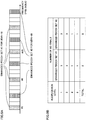
- FIG. 7 and FIG. 8 provide diagrams to explain examples of forming search spaces when DCI is mapped in localized mapping in an enhanced PDCCH set.
- the number of search space candidates per enhanced PDCCH set is configured such that the number of times of blind decoding in user terminals UE does not increase compared to the case where no enhanced PDCCH set is provided.
- N ECCE is the total number of ECCEs per enhanced PDCCH set (eight in FIG. 7 ).
- L is the aggregation level.
- i 0, ... , L-1.
- m' is equal to m
- m 0, ... , M (L) -1.
- the number of search space candidates is "2" if no enhanced PDCCH set is provided. Consequently, it is not possible to provide search space candidates for all of enhanced PDCCH sets 1 to 6. In this case, for example, it may be possible to select PRB pairs randomly based on C-RNTIs (Cell-Radio Network Temporary IDs) and so on, and form the search space candidates with the ECCEs in the selected PRB pairs.
- C-RNTIs Cell-Radio Network Temporary IDs
- the number of search space candidates per enhanced PDCCH set is configured such that the number of times of blind decoding in user terminals UE does not increase compared to the case where no enhanced PDCCH set is provided.
- the number of search space candidates is "6" if no enhanced PDCCH set is provided, so that the number of search space candidates is "3" in both enhanced PDCCH sets 1 and 2.
- the ECCEs to constitute the search space candidates for each enhanced PDCCH set are determined based on, for example, the hash function shown in equation 1, cases might occur where the three search space candidates of each enhanced PDCCH set are not all placed in different PRB pairs.
- ECCE #0 is determined to be the first search space candidate of enhanced PDCCH set 1 by above equation 1.
- ECCEs #1 and #2 are determined to be the second and third search space candidates of enhanced PDCCH set 1, respectively.
- ECCEs #0 to #3 of enhanced PDCCH set 1 are all included in PRB pair #0. Consequently, the three search space candidates of enhanced PDCCH set 1 are all placed in the same PRB pair #0.
- ECCE #7 is determined to be the first search space candidate in enhanced PDCCH set 2 by above equation 1.
- ECCEs #8 and #9 are determined to be the second and third search space candidates of enhanced PDCCH set 2, respectively.
- ECCE #7 of enhanced PDCCH set 2 is included in PRB pair #10, and ECCE #8 and #9 are included in PRB pair #27. Consequently, the two search space candidates of enhanced PDCCH set 2 are placed in the same PRB pair #27.
- the present inventors have studied a method of forming search space candidates, whereby frequency scheduling gain by localized mapping of DCI can be achieved, even when the number of enhanced PDCCH sets to be configured for each user terminal UE is smaller than the number of search space candidates as of when no enhanced PDCCH set is provided (for example, when K ⁇ 6), and arrived at the present invention.
- a radio base station configures a plurality of enhanced PDCCH sets (resource sets) that are each formed by including a plurality of resource blocks allocated to the enhanced PDCCH. Also, the radio base station determines the enhanced control channel elements to constitute a plurality of search space candidates above such that a plurality of search space candidates of each enhanced PDCCH set are all placed in different resource blocks. A user terminal UE blind-decodes the enhanced control channel elements that are determined thus, and acquires the DCI for the user terminal UE.
- the resource blocks are the frequency resource units to constitute the enhanced PDCCH sets, and are, for example, PRB pairs, PRBs and so on. Although examples will be described below where PRB pairs are used as resource blocks, this is by no means limiting.
- the resource blocks are formed by including a plurality of enhanced control channel elements.
- the enhanced control channel elements are the units of resource allocation to DCI that is to be transmitted in enhanced PDCCHs.
- An enhanced control channel element may be referred to as, for example, an "ECCE,” an “eCCE” and so on.
- an enhanced control channel elements will be referred to as an "ECCE” below and one resource block is formed with four ECCEs, this is by no means limiting.
- the number of ECCEs aggregated and allocated to one piece of DCI (aggregation level) is, for example, 1, 2, 4, 8 and 16, this is by no means limiting.
- the ECCEs may be assigned index numbers on a per enhanced PDCCH set basis.
- the resource blocks may be formed by including a plurality of enhanced resource element groups (eREGs). For example, it is possible to form one resource block with sixteen eREGs, and form one eREG with nine REs (resource elements). Also, one ECCE may be formed with four eREGs. In this case, the ECCEs may be mapped to resource blocks in eREG units.
- eREGs enhanced resource element groups
- the radio base station may determine the ECCEs to constitute each search space candidate based on the total number of ECCEs, N ECCE , in the PRB pairs constituting each enhanced PDCCH set, and the number of search space candidates in each enhanced PDCCH set, M set (L) , per aggregation level L.
- the radio base station determines the ECCEs to constitute each search space candidate based on the hash function shown in equation 3: L Y k + m ′ ⁇ N ECCE L ⁇ M set L ⁇ mod ⁇ N ECCE / L ⁇ + i
- N ECCE is the total number of ECCEs in the PRB pairs constituting each enhanced PDCCH set -- that is, the total number of ECCEs per enhanced PDCCH set.
- FIG. 9 is a diagram to explain a method of forming search space candidates according to the first example.
- the PRB pairs to constitute enhanced PDCCH sets 1 and 2 are alternately placed in units of two PRB pairs that are consecutive along the frequency direction.
- the PRB pairs to constitute each enhanced PDCCH set alternately it is possible to distribute each enhanced PDCCH over the frequency direction.
- the arrangement shown in FIG. 9 is only an example and is by no means limiting.
- the PRB pairs to constitute each enhanced PDCCH pair may be placed in units of one PRB pair.
- the PRB pairs to constitute the enhanced PDCCH sets do not have to be placed alternately.
- the ECCEs to constitute each PRB pair are assigned index numbers on a per enhanced PDCCH set basis. For example, index numbers #0 to #23, which are consecutive along the frequency direction, are assigned to all of the twenty-four ECCEs included in PRB pairs #0, #1, #18, #19, #36 and #37 constituting enhanced PDCCH set 1.
- the total number of ECCEs per enhanced PDCCH set, N ECCE is "24." Also, the number of search space candidates per enhanced PDCCH set, M set (L) , is "3" when the aggregation level L is 1 and 2, and “1" when the aggregation level L is 4 and 8.
- ECCEs #0, #8 and #16 of enhanced PDCCH set 1 are included in PRB pairs #0, #18 and #36, respectively. Consequently, the three search space candidates of enhanced PDCCH set 1 at aggregation level 2 are all placed in different PRB pairs.
- ECCEs #0, #8 and #16 of enhanced PDCCH set 2 are included in PRB pairs #9, #27 and #45, respectively. Consequently, the three search space candidates of enhanced PDCCH set 2 at aggregation level 2 are also all placed in different PRB pairs.
- the ECCEs to constitute each search space candidate are determined taking into account a predetermined parameter Y k , which varies per subframe. Consequently, it is possible to randomize the ECCEs to constitute each search space candidate on a per subframe basis, and, furthermore, reduce the probability of blocking.
- the radio base station may determine the ECCEs to constitute each search space candidate based on the hash function shown in equation 4, instead of above equation 3: L Y k + ⁇ m N ECCE L ⁇ M set L ⁇ mod ⁇ N ECCE / L ⁇ + i
- N ECCE is the total number of ECCEs in the PRB pairs constituting each enhanced PDCCH set -- that is, the total number of ECCEs per enhanced PDCCH set.
- the radio base station may determine the ECCEs to constitute each search space candidate of each component carrier based on carrier indicators.
- cross-carrier scheduling refers to using the enhanced PDCCH or PDCCH of a given CC (for example, CC #1) to allocate the PDSCH and PUSCH of that CC and other CCs (for example, CC #1 and CC #2).
- CC component carriers
- cross-carrier scheduling is executed using enhanced PDCCHs, in the PRB pairs constituting the enhanced PDCCH of a given CC (for example, CC #1), the search space candidates for that CC and other CCs (for example, CC #1 and CC #2) are placed.
- carrier indicators serve as indicators that show to which CC DCI pertains to, and are set in the CIF (Carrier Indicator Field) attached to the DCI.
- CIF Carrier Indicator Field
- the CIF is formed with three bits.
- the CIF configuration values "000" to "100” may be associated with CC #1 to CC #5, respectively.
- the number of CIF bits is determined depending on the number of CCs to be aggregated in carrier aggregation, and is by no means limited to three bits.
- a carrier indicator may be referred to as a "CI,” a "CC indicator,” a “carrier indicator field value,” a "ServCellIndex” and so on.
- the radio base station may determine the ECCEs to constitute each search space candidate of each component carrier based on the hash function shown in equation 5: L Y k + ⁇ m N ECCE L ⁇ M set L ⁇ + n CIF mod ⁇ N ECCE / L ⁇ + i
- N ECCE is the total number of ECCEs in the PRB pairs constituting each enhanced PDCCH set -- that is, the total number of ECCEs per enhanced PDCCH set.
- n CIF is the above-described carrier indicator. Note that n CIF may be a carrier indicator itself, or may be a predetermined parameter that is associated with that carrier indicator.
- the three search space candidates of enhanced PDCCH set 1 of CC #1 and CC #2 at aggregation level 1 are all placed in different PRB pairs #0, #18 and #36, respectively.
- the three search space candidates of enhanced PDCCH set 1 of CC #1 and CC #2 at aggregation level 1 are all placed in different PRB pairs #9, #27 and #45, respectively.
- the ECCEs to constitute each search space candidate of each CC are determined based on the carrier indicator n CIF of each CC, so that, even when cross-carrier scheduling is applied to the enhanced PDCCHs, it is still possible to place a plurality of search space candidates of each enhanced PDCCH set all in different PRB pairs. Note that the equation to determine the ECCEs to constitute each search space candidate of each CC is not limited to above equation 5 as long as the carrier indicator n CIF is taken into account.
- FIG. 10 is a diagram to show an example of a method of forming search space candidates according to the second example.
- FIG. 10 shows a case where two enhanced PDCCH sets are configured for each user terminal UE and each enhanced PDCCH set is formed with six PRB pairs. Also, in FIG. 10 , distributed mapping is applied to enhanced PDCCH set 1 and localized mapping is applied to enhanced PDCCH set 2. In this way, in FIG. 10 , the number of enhanced PDCCH sets (KD) where distributed mapping is applied, the number of enhanced PDCCH sets (KL) where localized mapping is applied are both set to "1."
- the number of search space candidates of each enhanced PDCCH set is configured such that the number of times of blind decoding in user terminals UE does not increase.
- the number of search space candidates is set to "0" in enhanced PDCCH 1, and set to "6" in enhanced PDCCH set 2. Since localized mapping is applied to enhanced PDCCH set 2, it becomes easier to achieve frequency scheduling gain by increasing the number of search space candidates.
- the number of search space candidates is set to "2" with enhanced PDCCH 1, and set to "0" with enhanced PDCCH set 2. This is because the number of search space candidates is small when the aggregation level is large and therefore the frequency scheduling gain in localized mapping decreases, and because, in an environment in which channel quality is poor and which requires a large aggregation level, distributed mapping that can achieve frequency diversity gain is more suitable.
- the PRB pairs to constitute enhanced PDCCH sets 1 and 2 are placed alternately, in one-PRB pair units, along the frequency direction.
- aggregation level 8 to aggregate eight ECCEs is not supported. Consequently, when one PRB pair is formed with four ECCEs, it is possible to place the PRB pair that constitutes enhanced PDCCH set 2 in one-PRB pair units.
- FIG. 11 is a diagram to explain a method of forming search space candidates according to the third example. Similar to FIG. 10 , in FIG. 11 , two enhanced PDCCH sets are configured for each user terminal UE, distributed mapping is applied to enhanced PDCCH set 1, and localized mapping is applied to enhanced PDCCH set 2. Also, it is equally possible to apply localized mapping to enhanced PDCCH set 1 and apply distributed mapping to enhanced PDCCH set 2 as well.
- enhanced PDCCH sets 1 and 2 are not formed with different PRB pairs as shown in FIG. 10 , but are formed with overlapping PRB pairs.
- one PRB pair is formed by including eight eREGs for enhanced PDCCH set 1 and eight eREGs for enhanced PDCCH set 2.
- ECCEs are mapped to the PRB pair in eREG units.
- the eight eREGs (#2, #3, #6, #7, #10, #11, #14 and #15) in PRB pair #0 are allocated to enhanced PDCCH set 2 where localized mapping is applied.
- four eREGs (#2, #6, #10 and #11) constitute ECCE #0 for localized mapping.
- four eREGs (#3, #7, #11 and #15) constitute ECCE #1 for localized mapping.
- eREGs and one ECCE are associated with each other so that the four eREGs to constitute one ECCE are included in the same PRB pair.
- eREGs #2, #6, #10 and #14 to constitute ECCE #0 for localized mapping are all included in PRB pair #0.
- eREGs and one ECCE are associated with each other so that the four eREGs to constitute one ECCE are all included in different PRB pairs.
- eREGs #0, #4, #8 and #12 to constitute ECCE #0 for distributed mapping are all included in different PRB pairs #0, #9, #18 and #27, respectively.
- enhanced PDCCH set 2 where localized mapping is applied, it is possible to determine the ECCEs to constitute each search space candidate using the hash function shown in above equation 3. Note that, with enhanced PDCCH set 1 where distributed mapping is applied, it is possible to use the hash function shown in above equation 1.
- FIG. 12 is a diagram to explain a method of forming search space candidates according to the fourth example.
- two enhanced PDCCH sets are configured for each user terminal UE, distributed mapping is applied to enhanced PDCCH set 1, and localized mapping is applied to enhanced PDCCH set 2.
- enhanced PDCCH sets 1 and 2 are not formed with the same number of PRBs, but are formed with different numbers of PRBs.
- enhanced PDCCH set 1 is formed with five PRB pairs.
- enhanced PDCCH set 2 is formed with eight PRB pairs, which are comprised of five PRB pairs that are used on an overlapping basis with enhanced PDCCH set 1, with an addition of three PRB pairs that are used on a dedicated basis.
- the ratios of the numbers of eREGs to constitute enhanced PDCCH sets 1 and 2 are not the same like in FIG. 11 , but are different.
- one PRB pair is formed by including twelve eREGs for enhanced PDCCH set 1 and four eREGs for enhanced PDCCH set 2. This ratios may be determined by the specifications, or may be reported by way of higher layer signaling.
- the four eREGs (#3, #7, #11 and #15) in PRB pair #0 that are used in enhanced PDCCH sets 1 and 2 on an overlapping basis are allocated to enhanced PDCCH set 2 where localized mapping is applied.
- These four eREGs (#3, #7, #11 and #15) constitute ECCE #0 for localized mapping.
- PRB pair #45 which is used by enhanced PDCCH set 2 on a dedicated basis
- four ECCEs #5 to #8 for localized mapping are formed with sixteen eREGs (#0 to #15).
- ECCE #5 of PRB pair #45 is formed with four eREGs (#0, #4, #8 and #12).
- one ECCE in one PRB pair may be formed with four distributed eREGs, not with four consecutive eREGs.
- FIG. 13 is a diagram to explain a method of forming search space candidates according to the fifth example.
- two enhanced PDCCH sets are configured for each user terminal UE, distributed mapping is applied to enhanced PDCCH set 1, and localized mapping is applied to enhanced PDCCH set 2.
- the configurations of enhanced PDCCH sets 1 and 2 shown in FIGs. 9 to 13 are only examples and are by no means limiting.
- the number of eREGs per PRB pair and the number of eREGs per ECCE are not limited to the ones shown in FIGs. 11 to 13 .
- the configurations shown in FIGs. 9 to 13 are applicable even when the number of enhanced PDCCH sets is two or greater.
- the ECCEs to constitute each search space candidate may be determined using above equation 4.
- the ECCEs to constitute each search space candidate of each CC may be determined based on carrier indicators.
- the ECCEs to constitute each search space candidate of each CC may be determined using above equation 5.
- FIG. 14 is a schematic configuration diagram of a radio communication system according to the present embodiment.
- the radio communication system shown in FIG. 14 is a system to accommodate, for example, the LTE system or SUPER 3G.
- This radio communication system adopts carrier aggregation to group a plurality of fundamental frequency blocks (component carriers) into one, where the system band of the LTE system constitutes one unit.
- this radio communication system may be referred to as "IMT-Advanced,” or may be referred to as "4G” or "FRA (Future Radio Access).”
- a radio communication system 1 includes a radio base station 11 that forms a macro cell C1, and radio base stations 12a and 12b that form small cells C2, which are placed inside the macro cell C1 and which are narrower than the macro cell C1. Also, in the macro cell C1 and in each small cell C2, user terminals 20 are placed. The user terminals 20 are configured to be able to perform radio communication with both the radio base station 11 and the radio base stations 12.
- a carrier of a relatively low frequency band for example, 2 GHz
- a wide bandwidth referred to as, for example, "conventional carrier,” “legacy carrier” and so on.
- a carrier of a relatively high frequency band for example, 3.5 GHz and so on
- a narrow bandwidth may be used, or the same carrier as that used between the user terminals 20 and the radio base station 11 may be used.
- the radio base station 11 and each radio base station 12 are connected by wire connection or by wireless connection.
- the radio base station 11 and the radio base stations 12 are each connected with a higher station apparatus 30, and are connected with a core network 40 via the higher station apparatus 30.
- the higher station apparatus 30 may be, for example, an access gateway apparatus, a radio network controller (RNC), a mobility management entity (MME) and so on, but is by no means limited to these.
- RNC radio network controller
- MME mobility management entity
- each radio base station 12 may be connected with the higher station apparatus via the radio base station 11.
- the radio base station 11 is a radio base station having a relatively wide coverage, and may be referred to as an "eNodeB,” a “radio base station apparatus,” a “transmission point” and so on.
- the radio base stations 12 are radio base stations having local coverages, and may be referred to as “pico base stations,” “femto base stations,” “Home eNodeBs,” “RRHs (Remote Radio Heads),” “micro base stations,” “transmission points” and so on.
- the radio base stations 11 and 12 will be collectively referred to as “radio base station 10," unless distinction needs to be drawn.
- Each user terminal 20 is a terminal that supports various communication schemes such as LTE, LTE-A and so on, and may be both a mobile communication terminal and a fixed communication terminal.
- OFDMA Orthogonal Frequency Division Multiple Access
- SC-FDMA Single-Carrier Frequency Division Multiple Access
- OFDMA is a multi-carrier transmission scheme to perform communication by dividing a frequency band into a plurality of narrow frequency bands (subcarriers) and mapping data to each subcarrier.
- SC-FDMA is a single-carrier transmission scheme to reduce interference between terminals by dividing the system band into bands formed with one or continuous resource blocks, per terminal, and allowing a plurality of terminals to use mutually different bands.
- Downlink communication channels include a PDSCH (Physical Downlink Shared Channel), which is used by each user terminal 20 on a shared basis, and downlink L1/L2 control channels (PDCCH, PCFICH and PHICH).
- PDSCH Physical Downlink Shared Channel
- PDCCH Physical Downlink Control CHannel
- the number of OFDM symbols to use for the PDCCH is transmitted by the PCFICH (Physical Control Format Indicator Channel).
- HARQ ACK and NACK for the PUSCH are transmitted by the PHICH (Physical Hybrid-ARQ Indicator CHannel).
- scheduling information for the PDSCH and the PUSCH and so on may be transmitted by the enhanced PDCCH (referred to as, for example, an "enhanced physical downlink control channel,” an "ePDCCH,” an “E-PDCCH,” an “FDM-type PDCCH” and so on).
- This enhanced PDCCH (enhanced downlink control channel) is frequency-division-multiplexed with the PDSCH (downlink shared data channel), and used to cover the shortage of the capacity of the PDCCH.
- Uplink control channels include the PUSCH (Physical Uplink Shared CHannel), which is used by each user terminal 20 on a shared basis as an uplink data channel, and the PUCCH (Physical Uplink Control CHannel), which is an uplink control channel. User data and higher control information are transmitted by this PUSCH. Also, by means of the PUCCH, downlink radio quality information (CQI: Channel Quality Indicator), ACK/NACK and so on are transmitted.
- PUSCH Physical Uplink Shared CHannel
- PUCCH Physical Uplink Control CHannel
- FIG. 15 is a diagram to show an overall structure of a radio base station 10 (which may be either the radio base station 11 or 12) according to the present embodiment.
- the radio base station 10 has a plurality of transmitting/receiving antennas 101 for MIMO transmission, amplifying sections 102, transmitting/receiving sections 103, a baseband signal processing section 104, a call processing section 105 and a transmission path interface 106.
- User data to be transmitted from the radio base station 10 to the user terminal 20 on the downlink is input from the higher station apparatus 30, into the baseband signal processing section 104, via the transmission path interface 106.
- a PDCP layer process In the baseband signal processing section 104, a PDCP layer process, division and coupling of user data, RLC (Radio Link Control) layer transmission processes such as an RLC retransmission control transmission process, MAC (Medium Access Control) retransmission control, including, for example, an HARQ transmission process, scheduling, transport format selection, channel coding, an inverse fast Fourier transform (IFFT) process and a precoding process are performed, and the result is transferred to each transmitting/receiving section 103. Furthermore, downlink control channel signals are also subjected to transmission processes such as channel coding and an inverse fast Fourier transform, and are transferred to each transmitting/receiving section 103.
- RLC Radio Link Control
- MAC Medium Access Control
- the baseband signal processing section 104 reports, to the user terminal 20, control information for allowing communication in the cell, through a broadcast channel.
- the information for allowing communication in the cell includes, for example, the uplink or downlink system bandwidth and so on.
- Each transmitting/receiving section 103 converts the baseband signals, which are pre-coded and output from the baseband signal processing section 104 on a per antenna basis, into a radio frequency band.
- the amplifying sections 102 amplify the radio frequency signals having been subjected to frequency conversion, and transmit the results through the transmitting/receiving antennas 101.
- the radio frequency signals that are received in the transmitting/receiving antennas 101 are each amplified in the amplifying sections 102, converted into baseband signals through frequency conversion in each transmitting/receiving section 103, and input in the baseband signal processing section 104.
- the user data that is included in the input baseband signals is subjected to an FFT process, an IDFT process, error correction decoding, a MAC retransmission control receiving process, and RLC layer and PDCP layer receiving processes, and the result is transferred to the higher station apparatus 30 via the transmission path interface 106.
- the call processing section 105 performs call processing such as setting up and releasing communication channels, manages the state of the radio base station 10 and manages the radio resources.
- FIG. 16 is a diagram to show an overall structure of a user terminal 20 according to the present embodiment.
- the user terminal 20 has a plurality of transmitting/receiving antennas 201 for MIMO transmission, amplifying sections 202, transmitting/receiving sections (receiving sections) 203, a baseband signal processing section 204, and an application section 205.
- radio frequency signals that are received in the plurality of transmitting/receiving antennas 201 are each amplified in the amplifying sections 202, and subjected to frequency conversion and converted into baseband signals in the transmitting/receiving sections 203. These baseband signals are subjected to receiving processes such as an FFT process, error correction decoding and retransmission control, in the baseband signal processing section 204.
- downlink user data is transferred to the application section 205.
- the application section 205 performs processes related to higher layers above the physical layer and the MAC layer. Also, in the downlink data, broadcast information is also transferred to the application section 205.
- uplink user data is input from the application section 205 to the baseband signal processing section 204.
- a retransmission control (H-ARQ (Hybrid ARQ)) transmission process channel coding, precoding, a DFT process, an IFFT process and so on are performed, and the result is transferred to each transmitting/receiving section 203.
- the baseband signals that are output from the baseband signal processing section 204 are converted into a radio frequency band in the transmitting/receiving sections 203.
- the amplifying sections 202 amplify the radio frequency signals having been subjected to frequency conversion, and transmit the result from the transmitting/receiving antennas 201.
- FIG. 17 is a function structure diagram of the baseband signal processing section 104 provided in the radio base station 10 according to the present embodiment, and part of higher layers. Note that, although FIG. 17 primarily shows downlink (transmitting) functional configurations, the radio base station 10 may have uplink (receiving) functional configurations as well.
- the radio base station 10 has a higher layer control information generating section 300, a data generating section 301, a channel coding section 302, a modulation section 303, a mapping section 304, a downlink control information generating section 305, a shared control information generating section 306, channel coding sections 307, modulation sections 308, a control channel multiplexing section 309, an interleaving section 310, a measurement reference signal generating section 311, an IFFT section 312, a mapping section 313, a demodulation reference signal generating section 314, a weight multiplication section 315, a CP inserting section 316, and a scheduling section 317.
- the control channel multiplexing section 309 and the interleaving section 310 may be omitted.
- the higher layer control information generating section 300 generates higher layer control information on a per user terminal 20 basis.
- the higher layer control information is control information that is sent through higher layer signaling (for example, RRC signaling) and includes, for example, enhanced PDCCH allocation information.
- the enhanced PDCCH allocation information refers to, for example, the PRB pairs (resource blocks) that constitute each enhanced PDCCH set configured for the user terminal 20.
- the data generating section 301 generates downlink user data per user terminal 20.
- the downlink user data that is generated in the data generating section 301 and the higher layer control information that is generated in the higher layer control information generating section 300 are input in the channel coding section 302 as downlink data to be transmitted in the PDSCH.
- the channel coding section 302 performs channel coding of the downlink data for each user terminal 20 in accordance with the coding rate determined based on feedback information from each user terminal 20.
- the modulation section 303 modulates the downlink data having been subjected to channel coding, in accordance with the modulation scheme determined based on feedback information from each user terminal 20.
- the mapping section 304 maps the modulated downlink data in accordance with commands from the scheduling section 317.
- the downlink control information generating section 305 generates UE-specific downlink control information (DCI) on a per user terminal 20 basis.
- the UE-specific downlink control information includes PDSCH allocation information (DL grants), PUSCH allocation information (UL grants) and so on.
- the shared control information generating section 306 generates shared (cell-specific) control information that is shared between cells.
- the downlink control information generated in the downlink control information generating section 305 and the shared control information generated in the shared control information generating section 306 are input in the channel coding sections 307 as downlink control information to be transmitted in the PDCCH or the enhanced PDCCH.
- the channel coding sections 307 perform channel coding of the downlink control information received as input, in accordance with the coding rate designated by the scheduling section 317, which will be described later.
- the modulation sections 308 modulate the downlink control information after channel coding.
- the downlink control information to be transmitted in the PDCCH is input from the modulation sections 308 into the control channel multiplexing section 309 and multiplexed.
- the downlink control information that is multiplexed in the control channel multiplexing section 309 is interleaved in the interleaving section 310.
- the interleaved downlink control information is input in the IFFT section 312, with measurement reference signals (channel state information-reference signals (CSI-RSs), cell-specific reference signals (CRSs) and so on) generated in the measurement reference signal section 311.
- CSI-RSs channel state information-reference signals
- CRSs cell-specific reference signals
- the mapping section 313 maps the downlink control information in predetermined allocation units (for example, eCCEs or eREGs) in accordance with commands from the scheduling section 317, which will be described later.
- the mapping section 313 may map the downlink control information using distributed mapping in accordance with commands from the scheduling section 317, or map the downlink control information using localized mapping.
- the mapped downlink control information is input in the weight multiplication section 315, with the downlink data to be transmitted in the PDSCH (that is, the downlink data mapped in the mapping section 314) and the demodulation reference signals (DM-RSs) generated in the demodulation reference signal generating section 314.
- the weight multiplication section 315 multiplies the downlink data to be transmitted by the PDCSH, the downlink control information to be transmitted by the enhanced PDCCH and the demodulation reference signals, by user terminal 20-specific precoding weights, and pre-codes them.
- the pre-coded transmission data is input in the IFFT section 312, and converted from frequency domain signals into time sequence signals through an inverse fast Fourier transform. Cyclic prefixes (CPs) to function as guard intervals are inserted in the output signals from the IFFT section 312 by the CP inserting section 316, and the signals are output to the transmitting/receiving sections 103.
- CPs Cyclic prefixes
- the scheduling section 317 allocates radio resources to the downlink user data, the downlink control information and so on, based on command information from the higher station apparatus 30 and feedback information from each user terminal 20 (for example, channel state information (CSI), which includes channel quality indicators (CQIs) and rank indicators (RIs) and so on).
- CSI channel state information
- CQIs channel quality indicators
- RIs rank indicators
- the scheduling section 317 configures a plurality of enhanced PDCCH sets (resource sets) for each user terminal 20. Also, the scheduling section 317 determines the PRB pairs (resource block) to constitute each enhanced PDCCH set. Furthermore, the scheduling section 317 determines the enhanced PDCCH sets to use, based on the number of user terminals 20 and so on. The scheduling section 317 constitutes the configuring section of the present invention.
- the scheduling section 317 determines the ECCEs (enhanced control channel elements) to constitute each search space candidate in such a way that a plurality of search space candidates of each enhanced PDCCH set where localized mapping is applied are all placed in different PRB pairs (resource blocks).
- the scheduling section 317 constitutes the determining section of the present invention.
- the scheduling section 317 may determine the ECCEs to constitute each search space candidate based on the total number of ECCEs (N ECCE ) in a plurality of PRB pairs constituting each enhanced PDCCH set where localized mapping is applied, and the number of search space candidates in each enhanced PDCCH set at each aggregation level (M set (L) ).
- N ECCE the total number of ECCEs
- M set (L) the number of search space candidates in each enhanced PDCCH set at each aggregation level
- the scheduling section 317 selects, from a plurality of PRB pairs constituting an enhanced PDCCH set, the PRB pairs to be subject to localized mapping of DCI, based on channel quality information (for example, CQIs) fed back from the user terminal 20.
- the scheduling section 317 commands the mapping section 313 to map DCI in localized mapping to the ECCEs constituting the search spaces placed in the selected PRB pairs.
- the scheduling section 317 constitutes the selection section of the present invention.
- the scheduling section 317 may determine the ECCEs to constitute a plurality of search space candidates of an enhanced PDCCH set where distributed mapping is applied, by using above equation 1.
- the scheduling section 317 may determine the ECCEs to constitute a plurality of search space candidates of an enhanced PDCCH set where localized mapping is applied, by using above equation 4.
- the scheduling section 317 may determine the ECCEs to constitute a plurality of search space candidates of an enhanced PDCCH set where localized mapping is applied, based on carrier indicators. To be more specific, the scheduling section 317 may determine the ECCEs using above equation 5.
- FIG. 18 is a function structure diagram of the baseband signal processing section 204 provided in the user terminal 20.
- the user terminal 20 has, as downlink (receiving) functional configurations, a CP removing section 401, an FFT section 402, a demapping section 403, a deinterleaving section 404, a PDCCH demodulation section 405, an enhanced PDCCH demodulation section 406, a PDSCH demodulation section 407, and a channel estimation section 408.
- Downlink signals received from the radio base station 10 as received data have the cyclic prefixes (CPs) removed in the CP removing section 401.
- the downlink signals, from which the CPs have been removed, are input in the FFT section 402.
- the FFT section 402 performs a fast Fourier transform (FFT) on the downlink signals, converts the time domain signals into frequency domain signals, and inputs these signals in the demapping section 403.
- the demapping section 403 demaps the downlink signals. Downlink control information that is output from the demapping section 403 is deinterleaved in the deinterleaving section 404.
- the PDCCH demodulation section 405 performs blind decoding, demodulation, channel decoding and so on of the downlink control information (DCI) output from the deinterleaving section 404, based on the result of channel estimation in a channel estimation section 408, which will be described later. To be more specific, the PDCCH demodulation section 405 blind-decodes the search space candidates reported from the radio base station 10 in advance or search space candidates that are determined in advance, and acquires the downlink control information. The PDCCH demodulation section 405 outputs the PDSCH allocation information included in the DCI to the PDSCH demodulation section 407.
- DCI downlink control information
- the enhanced PDCCH demodulation section 406 performs blind decoding, demodulation, channel decoding and so on of the downlink control information (DCI) output from the demapping section 403, based on the result of channel estimation in the channel estimation section 409, which will be described later.
- DCI downlink control information
- the enhanced PDCCH demodulation section 406 detects the PRB pairs to constitute each enhanced PDCCH set, based on enhanced PDCCH allocation information input from the PDSCH demodulation section 407.
- the enhanced PDCCH demodulation section 406 determines the ECCEs (enhanced control channel elements) to constitute each of a plurality of search space candidates, all placed in different PRB pairs (resource blocks) constituting each enhanced PDCCH set (resource sets).
- the enhanced PDCCH demodulation section 406 may determine the ECCEs to constitute each search space candidate, based on the total number of ECCEs (N ECCE ) in a plurality of PRB pairs constituting each enhanced PDCCH set where localized mapping is applied, and the number of search space candidates in each enhanced PDCCH set at each aggregation level (M set (L) ).
- N ECCE the total number of ECCEs
- M set (L) the number of search space candidates in each enhanced PDCCH set at each aggregation level
- the enhanced PDCCH demodulation section 406 blind-decodes the ECCEs determined as described above, and acquires the DCI.
- the enhanced PDCCH demodulation section 406 outputs the PDSCH allocation information included in the DCI to the PDSCH demodulation section 407.
- the enhanced PDCCH demodulation section 406 constitutes the determining section and the acquisition section of the present invention.
- the enhanced PDCCH demodulation section 406 may determine the ECCEs to constitute a plurality of search space candidates of an enhanced PDCCH set where localized mapping is applied, using above equation 4.
- the enhanced PDCCH demodulation section 406 may determine the ECCEs to constitute a plurality of search space candidates of the enhanced PDCCH set of each CC, based on carrier indicators. To be more specific, the enhanced PDCCH demodulation section 406 may determine the ECCEs using above equation 5.
- the PDSCH demodulation section 406 performs demodulation and channel decoding and so on of the downlink data output from the demapping section 403, based on the result of channel estimation in the channel estimation section 408, which will be described later.
- the PDSCH demodulation section 407 demodulates the PDSCH allocated to the subject user terminal based on the downlink control information demodulated in the PDCCH demodulation section 405 or the enhanced PDCCH demodulation section 406, and acquires the downlink data (downlink user data and higher layer control information) for the subject user terminal.
- the channel estimation section 408 performs channel estimation using demodulation reference signals (DM-RSs), measurement reference signals (CRSs and CSI-RSs) and so on.
- the channel estimation section 408 outputs the result of channel estimation by the measurement reference signals (CRSs and CSI-RSs) to the PDCCH demodulation section 405.
- the channel estimation section 408 outputs the result of channel estimation by the demodulation reference signals (DM-RSs) to the PDSCH demodulation section 406 and to the enhanced PDCCH demodulation section 407.
- DM-RSs demodulation reference signals
- the radio base station 10 determines the ECCEs to constitute each search space candidate, by using, for example, equation 3, such that a plurality of search space candidates of each enhanced PDCCH set are all placed in different resource blocks.
- a plurality of search space candidates of each enhanced PDCCH set are all placed in different resource blocks. Consequently, even when the number of enhanced PDCCH sets that are configured for each user terminal 10 is smaller than the number of search space candidates as of when no enhanced PDCCH set is provided, it is still possible to achieve frequency scheduling gain by localized mapping of DCI.
- the parameter Y k which varies on a subframe basis, is taken into account, so that it is possible to reduce the probability of blocking.
- equation 4 when equation 4 is used instead of equation 3, it is possible to place a plurality of search space candidates of each enhanced PDCCH set all in different resource blocks.
- equation 5 by determining the ECCEs to constitute each search space candidate of each CC based on the carrier indicator n CIF of each CC, it is possible to place a plurality of search space candidates of each enhanced PDCCH set all in different PRB pairs even when cross-carrier scheduling is applied is applied to the enhanced PDCCHs.
Landscapes
- Engineering & Computer Science (AREA)
- Signal Processing (AREA)
- Computer Networks & Wireless Communication (AREA)
- Mobile Radio Communication Systems (AREA)
Claims (6)
- Station de base radio (11, 12) pour transmettre des informations de commande de liaison descendante (DCI) pour un terminal utilisateur (20) en utilisant un canal de commande amélioré de liaison descendante (E-PDCCH) qui est multiplexé par répartition en fréquence avec un canal de données partagé de liaison descendante (PDSCH), la station de base radio (11, 12) comprenant :une section de configuration (300) configurée pour configurer un ensemble de ressources pour le terminal utilisateur (20), l'ensemble de ressources comprenant une pluralité de blocs de ressource (PRB) allouée au canal de commande amélioré de liaison descendante (E-PDCCH) ; etune section de détermination (317) configurée pour déterminer des éléments de canal de commande amélioré (ECCE) pour constituer une pluralité de candidats d'espace de recherche de l'ensemble de ressources sur la base d'un nombre total d'éléments de canal de commande amélioré dans la pluralité de blocs de ressource (PRB) constituant l'ensemble de ressources, et un nombre de candidats d'espace de recherche à chaque niveau d'agrégation dans l'ensemble de ressources,caractérisée en ce que :les éléments de canal de commande amélioré (ECCE) sont spécifiés par des numéros d'indice qui sont attribués sur une base par ensemble de ressources, et les éléments de canal de commande amélioré (ECCE) sont spécifiés par des numéros d'indice représentés par
 NECCE est le nombre total d'éléments de canal de commande amélioré (ECCE) ;Mset (L) est le nombre de candidats d'espace de recherche à chaque niveau d'agrégation ;L est un niveau d'agrégation des éléments de canal de commande amélioré (ECCE) ;m = 0, ..., Mset (L) - 1;i = 0, ..., L- 1 ; etYk est un paramètre prédéterminé qui varie par sous-trame,
ou :quand une planification de sous-porteuses est appliquée au terminal utilisateur (20), les éléments de canal de commande amélioré (ECCE) sont spécifiés par un indicateur de porteuse, et les éléments de canal de commande amélioré (ECCE) sont spécifiés par des numéros d'indice représentés par NECCE est le nombre total des éléments de canal de commande amélioré (ECCE) ;Mset (L) est le nombre de candidats d'espace de recherche à chaque niveau d'agrégation ;L est un niveau d'agrégation des éléments de canal de commande amélioré (ECCE) ;m = 0, ..., Mset (L) - 1 ;i = 0, ..., L - 1 ;Yk est un paramètre prédéterminé qui varie par sous-trame ; etnCIF est l'indicateur de porteuse.
 - Station de base radio (11, 12) selon la revendication 1, comprenant en outre :une section de sélection (317) configurée pour sélectionner un bloc de ressource (PRB) parmi la pluralité de blocs de ressource (PRB) sur la base d'informations de qualité de canal provenant d'un terminal utilisateur (20) ; etune section de mappage (304) configurée pour mapper les informations de commande de liaison descendante (DCI) à au moins un parmi les éléments de canal amélioré (ECCE) constituant un candidat d'espace de recherche qui est placé dans le bloc de ressource sélectionné (PRB).
- Terminal utilisateur (20) pour recevoir des informations de commande de liaison descendante (DCI) à partir d'une station de base radio (11, 12) en utilisant un canal de commande amélioré de liaison descendante (E-PDCCH) qui est multiplexé par répartition en fréquence avec un canal de données partagé de liaison descendante (PDSCH), le terminal utilisateur (20) comprenant :une section de détermination (406) qui est configurée pour, quand le terminal utilisateur (20) est configuré avec un ensemble de ressources comprenant une pluralité de blocs de ressource (PRB) allouée au canal de commande amélioré de liaison descendante (E-PDCCH), déterminer des éléments de canal de commande amélioré (ECCE) pour constituer une pluralité de candidats d'espace de recherche de l'ensemble de ressources sur la base d'un nombre total d'éléments de canal de commande amélioré (ECCE) dans la pluralité de blocs de ressource (PRB) constituant l'ensemble de ressources, et un nombre de candidats d'espace de recherche à chaque niveau d'agrégation dans l'ensemble de ressources,caractérisé en ce que :les éléments de canal de commande amélioré (ECCE) sont spécifiés par des numéros d'indice qui sont attribués sur une base par ensemble de ressources, et les éléments de canal de commande amélioré (ECCE) sont spécifiés par des numéros d'indice représentés par
 NECCE est le nombre total des éléments de canal de commande amélioré (ECCE) ;Mset (L) est le nombre de candidats d'espace de recherche à chaque niveau d'agrégation ;L est un niveau d'agrégation des éléments de canal de commande amélioré (ECCE) ;m = 0, ..., Mset (L) - 1 ;i = 0, ..., L - 1 ; etYk est un paramètre prédéterminé qui varie par sous-trame,où :
ou :quand une planification de sous-porteuses est appliquée au terminal utilisateur (20), les éléments de canal de commande amélioré (ECCE) sont spécifiés par un indicateur de porteuse, et les éléments de canal de commande amélioré (ECCE) sont spécifiés par des numéros d'indice représentés par NECCE est le nombre total des éléments de canal de commande amélioré (ECCE) ;Mset (L) est le nombre de candidats d'espace de recherche à chaque niveau d'agrégation ;L est un niveau d'agrégation des éléments de canal de commande amélioré (ECCE) ;m = 0, ..., Mset (L) - 1 ;i = 0, ..., L - 1 ;Yk est un paramètre prédéterminé qui varie par sous-trame ; etnCIF est l'indicateur de porteuse.
 - Terminal utilisateur selon la revendication 3, comprenant en outre une section d'acquisition (406) configurée pour décoder en aveugle les éléments de canal de commande amélioré (ECCE) pour acquérir les informations de commande de liaison descendante (DCI).
- Système de radiocommunication dans lequel une station de base radio (11, 12) selon la revendication 1 est configurée pour transmettre des informations de commande de liaison descendante (DCI) pour un terminal utilisateur (20) selon la revendication 3.
- Procédé de radiocommunication dans lequel une station de base radio (11, 12) transmet des informations de commande de liaison descendante (DCI) pour un terminal utilisateur (20) en utilisant un canal de commande amélioré de liaison descendante (E-PDCCH) qui est multiplexé par répartition en fréquence avec un canal de données partagé de liaison descendante (PDSCH), le procédé de radiocommunication comprenant les étapes suivantes :dans la station de base radio (11, 12) :la configuration d'un ensemble de ressources pour le terminal utilisateur (20), l'ensemble de ressources comprenant une pluralité de blocs de ressource (PRB) allouée au canal de commande amélioré de liaison descendante (E-PDCCH) ; etla détermination d'éléments de canal de commande amélioré (ECCE) pour constituer une pluralité de candidats d'espace de recherche de l'ensemble de ressources sur la base d'un nombre total d'éléments de canal de commande amélioré (ECCE) dans la pluralité de blocs de ressource constituant l'ensemble de ressources, et un nombre de candidats d'espace de recherche à chaque niveau d'agrégation dans l'ensemble de ressources,caractérisé en ce que :les éléments de canal de commande amélioré (ECCE) sont spécifiés par des numéros d'indice qui sont attribués sur une base par ensemble de ressources, et les éléments de canal de commande amélioré (ECCE) sont spécifiés par des numéros d'indice représentés paroù :
 NECCE est le nombre total des éléments de canal de commande amélioré (ECCE) ;Mset (L) est le nombre de candidats d'espace de recherche à chaque niveau d'agrégation ;L est un niveau d'agrégation des éléments de canal de commande amélioré (ECCE) ;m = 0, ..., Mset (L) - 1 ;i = 0, ..., L - 1 ; etYk est un paramètre prédéterminé qui varie par sous-trame,
ou :quand une planification de sous-porteuses est appliquée au terminal utilisateur (20), les éléments de canal de commande amélioré (ECCE) sont spécifiés par un indicateur de porteuse, et les éléments de canal de commande amélioré (ECCE) sont spécifiés par des numéros d'indice représentés par NECCE est le nombre total des éléments de canal de commande amélioré (ECCE) ;Mset (L) est le nombre de candidats d'espace de recherche à chaque niveau d'agrégation ;L est un niveau d'agrégation des éléments de canal de commande amélioré (ECCE) ;m = 0, ..., Mset (L) - 1 ;i = 0, ..., L - 1 ;Yk est un paramètre prédéterminé qui varie par sous-trame ; etnCIF est l'indicateur de porteuse.
Applications Claiming Priority (4)
| Application Number | Priority Date | Filing Date | Title |
|---|---|---|---|
| JP2012216731 | 2012-09-28 | ||
| JP2012243093 | 2012-11-02 | ||
| JP2012255503A JP5771177B2 (ja) | 2012-09-28 | 2012-11-21 | 無線基地局、ユーザ端末、無線通信システム及び無線通信方法 |
| PCT/JP2013/070785 WO2014050302A1 (fr) | 2012-09-28 | 2013-07-31 | Station de base radio, terminal utilisateur, système et procédé de radiocommunication |
Publications (3)
| Publication Number | Publication Date |
|---|---|
| EP2903371A1 EP2903371A1 (fr) | 2015-08-05 |
| EP2903371A4 EP2903371A4 (fr) | 2016-06-22 |
| EP2903371B1 true EP2903371B1 (fr) | 2018-02-14 |
Family
ID=50387716
Family Applications (1)
| Application Number | Title | Priority Date | Filing Date |
|---|---|---|---|
| EP13840326.6A Active EP2903371B1 (fr) | 2012-09-28 | 2013-07-31 | Station de base radio, terminal utilisateur, système et procédé de radiocommunication |
Country Status (6)
| Country | Link |
|---|---|
| US (1) | US9832764B2 (fr) |
| EP (1) | EP2903371B1 (fr) |
| JP (1) | JP5771177B2 (fr) |
| CN (1) | CN104685950B (fr) |
| RU (1) | RU2584698C1 (fr) |
| WO (1) | WO2014050302A1 (fr) |
Families Citing this family (26)
| Publication number | Priority date | Publication date | Assignee | Title |
|---|---|---|---|---|
| EP2728775B1 (fr) * | 2011-06-29 | 2021-03-03 | LG Electronics Inc. | Procédé et appareil de réception d'informations de commande dans un système de communication sans fil |
| JP5781028B2 (ja) * | 2012-07-23 | 2015-09-16 | 株式会社Nttドコモ | 無線通信方法、無線基地局、ユーザ端末及び無線通信システム |
| CN103796309A (zh) * | 2012-10-31 | 2014-05-14 | 华为终端有限公司 | 控制信息的传输方法、基站及用户设备 |
| US9185716B2 (en) * | 2013-01-03 | 2015-11-10 | Samsung Electronics Co., Ltd. | Obtaining control channel elements of physical downlink control channels for cross-carrier scheduling |
| US10652768B2 (en) | 2015-04-20 | 2020-05-12 | Qualcomm Incorporated | Control channel based broadcast messaging |
| US10064217B2 (en) * | 2015-10-16 | 2018-08-28 | Samsung Electronics Co., Ltd. | Method and apparatus for enabling flexible numerology in multi-user MIMO system |
| CA3012033C (fr) * | 2016-01-27 | 2024-04-02 | Ntt Docomo, Inc. | Terminal utilisateur, station de base sans fil, et procede de communication sans fil |
| ES2969369T3 (es) * | 2016-07-29 | 2024-05-17 | Ntt Docomo Inc | Aparato y sistema |
| US10606069B2 (en) | 2016-08-01 | 2020-03-31 | Texas Instruments Incorporated | Ultrasound lens structure cleaner architecture and method |
| WO2018030300A1 (fr) * | 2016-08-10 | 2018-02-15 | シャープ株式会社 | Système de communication, dispositif station de base, dispositif terminal, procédé de communication et programme |
| ES2913681T3 (es) * | 2016-09-21 | 2022-06-03 | Ntt Docomo Inc | Terminal de usuario, método de comunicación por radio, estación base de radio y sistema de comunicación por radio |
| US10932247B2 (en) * | 2016-11-03 | 2021-02-23 | Lg Electronics Inc. | Method for configuring downlink control region in wireless communication system and device for same |
| CN108282290B (zh) * | 2017-01-06 | 2022-05-24 | 北京三星通信技术研究有限公司 | 一种通信系统中由终端和基站执行的方法及设备 |
| CN111343640A (zh) * | 2017-01-20 | 2020-06-26 | Oppo广东移动通信有限公司 | 基础参数集关联的资源的分别配置 |
| CN110192418B (zh) * | 2017-01-26 | 2021-09-14 | 华为技术有限公司 | 一种下行链路控制信息的处理方法及装置 |
| EP3577986A1 (fr) * | 2017-02-06 | 2019-12-11 | Intel IP Corporation | Segmentation de signalisation de commande de liaison descendante |
| US10608779B2 (en) * | 2017-02-06 | 2020-03-31 | Qualcomm Incorporated | Search space configuration for new radio (NR) system |
| AU2017418274B2 (en) * | 2017-06-15 | 2022-09-01 | Ntt Docomo, Inc. | User terminal and radio communication method |
| CN111066358B (zh) * | 2017-07-21 | 2023-07-25 | 株式会社Ntt都科摩 | 用户终端以及无线通信方法 |
| US11516788B2 (en) * | 2017-07-28 | 2022-11-29 | Ntt Docomo, Inc. | Terminal and radio communication method |
| JP2019075609A (ja) * | 2017-10-12 | 2019-05-16 | シャープ株式会社 | 端末装置、基地局装置、および、通信方法 |
| CN111527722B (zh) * | 2017-11-14 | 2023-05-02 | 交互数字专利控股公司 | 用于物理下行链路控制信道(pdcch)候选确定的方法 |
| EP3713321A4 (fr) * | 2017-11-16 | 2021-06-23 | Ntt Docomo, Inc. | Terminal d'utilisateur, et procédé de communications sans fil |
| EP3836501A4 (fr) * | 2018-08-09 | 2022-03-30 | NTT DoCoMo, Inc. | Terminal utilisateur et procédé de communication sans fil |
| US10966231B2 (en) * | 2018-09-28 | 2021-03-30 | Qualcomm Incorporated | Configuring aggregation level and physical downlink control channel candidates at a user equipment |
| CN113396619A (zh) * | 2018-12-11 | 2021-09-14 | 株式会社Ntt都科摩 | 用户终端以及无线通信方法 |
Family Cites Families (16)
| Publication number | Priority date | Publication date | Assignee | Title |
|---|---|---|---|---|
| WO2008003815A1 (fr) * | 2006-07-07 | 2008-01-10 | Nokia Corporation | Mécanisme d'attribution de ressources radio amélioré |
| KR101468490B1 (ko) * | 2007-05-02 | 2014-12-10 | 삼성전자주식회사 | 무선 통신 시스템에서 제어 채널들의 집합을 한정하여 송수신하는 방법 및 장치 |
| EP2456082B1 (fr) * | 2007-10-29 | 2014-06-11 | Panasonic Corporation | Appareil de station de base de communication sans fil, appareil de station mobile de communication sans fil et procédé d'attribution de canal de contrôle |
| US8238475B2 (en) * | 2007-10-30 | 2012-08-07 | Qualcomm Incorporated | Methods and systems for PDCCH blind decoding in mobile communications |
| WO2010098289A1 (fr) * | 2009-02-24 | 2010-09-02 | シャープ株式会社 | Système de communication sans fil, dispositif de station de base, dispositif de station mobile et procédé et programme de communication sans fil |
| CN103139819B (zh) * | 2009-08-28 | 2016-03-30 | 华为技术有限公司 | 确定搜索空间、候选控制信道资源的方法及装置 |
| EP2600547B1 (fr) * | 2010-07-26 | 2016-04-06 | LG Electronics Inc. | Rétroaction apériodique d'information d'état de canal dans un système d'accès sans fil de support d'agrégation multi-porteuse |
| WO2012039102A1 (fr) * | 2010-09-21 | 2012-03-29 | パナソニック株式会社 | Station de base, terminal, procédé d'émission et procédé de réception |
| KR101510582B1 (ko) * | 2011-06-15 | 2015-04-08 | 삼성전자주식회사 | 통신 시스템에서 물리 하향링크 제어 시그널링의 확장 |
| US8665811B2 (en) * | 2011-08-15 | 2014-03-04 | Motorola Mobility Llc | Reference signal for a control channel in wireless communication network |
| US8842628B2 (en) * | 2011-09-12 | 2014-09-23 | Blackberry Limited | Enhanced PDCCH with transmit diversity in LTE systems |
| CN102404076B (zh) * | 2011-11-07 | 2014-12-10 | 电信科学技术研究院 | 信息发送及盲检方法和设备 |
| US9054843B2 (en) * | 2012-01-30 | 2015-06-09 | Nokia Solutions And Networks Oy | Search space arrangement for control channel |
| US9198181B2 (en) * | 2012-03-19 | 2015-11-24 | Blackberry Limited | Enhanced common downlink control channels |
| KR102047698B1 (ko) | 2012-04-13 | 2019-12-04 | 엘지전자 주식회사 | 무선 통신 시스템에서 하향링크 제어 채널을 위한 검색 영역을 설정하는 방법 및 이를 위한 장치 |
| US8982693B2 (en) * | 2012-05-14 | 2015-03-17 | Google Technology Holdings LLC | Radio link monitoring in a wireless communication device |
-
2012
- 2012-11-21 JP JP2012255503A patent/JP5771177B2/ja active Active
-
2013
- 2013-07-31 CN CN201380050754.1A patent/CN104685950B/zh active Active
- 2013-07-31 EP EP13840326.6A patent/EP2903371B1/fr active Active
- 2013-07-31 US US14/431,329 patent/US9832764B2/en active Active
- 2013-07-31 RU RU2015112193/07A patent/RU2584698C1/ru active
- 2013-07-31 WO PCT/JP2013/070785 patent/WO2014050302A1/fr active Application Filing
Non-Patent Citations (1)
| Title |
|---|
| None * |
Also Published As
| Publication number | Publication date |
|---|---|
| CN104685950A (zh) | 2015-06-03 |
| EP2903371A4 (fr) | 2016-06-22 |
| WO2014050302A1 (fr) | 2014-04-03 |
| EP2903371A1 (fr) | 2015-08-05 |
| US20150282129A1 (en) | 2015-10-01 |
| RU2584698C1 (ru) | 2016-05-20 |
| JP2014112752A (ja) | 2014-06-19 |
| CN104685950B (zh) | 2016-12-28 |
| JP5771177B2 (ja) | 2015-08-26 |
| US9832764B2 (en) | 2017-11-28 |
Similar Documents
| Publication | Publication Date | Title |
|---|---|---|
| EP2903371B1 (fr) | Station de base radio, terminal utilisateur, système et procédé de radiocommunication | |
| US9756622B2 (en) | Radio base station, user terminal, radio communication system and radio communication method | |
| US9763240B2 (en) | Blind decoding method, radio base station, user terminal and radio communication system | |
| US9893863B2 (en) | Determining UL radio resources for delivery acknowledgement information of a DSCH when a plurality of resource sets of an enhanced DCCH are configured | |
| US9408204B2 (en) | Radio base station apparatus, user terminal, radio communication system and radio communication method | |
| US9491749B2 (en) | Radio communication method, radio communication system and radio base station | |
| US9380570B2 (en) | Radio base station apparatus, user terminal, radio communication system and radio communication method | |
| EP2811799A1 (fr) | Dispositif station de base sans fil, terminal utilisateur, système de communication sans fil et procédé de communication sans fil | |
| US9882694B2 (en) | Radio base station, user terminal, radio communication system and radio communication method | |
| JP6068860B2 (ja) | 無線通信方法、無線基地局、ユーザ端末及び無線通信システム | |
| JP6105693B2 (ja) | 無線通信方法、無線通信システム及び無線基地局 | |
| JP6106725B2 (ja) | 無線基地局、ユーザ端末、無線通信システム及び無線通信方法 | |
| EP2911463A1 (fr) | Procédé de communication radio, système de communication radio, station de base radio et terminal utilisateur |
Legal Events
| Date | Code | Title | Description |
|---|---|---|---|
| PUAI | Public reference made under article 153(3) epc to a published international application that has entered the european phase |
Free format text: ORIGINAL CODE: 0009012 |
|
| 17P | Request for examination filed |
Effective date: 20150413 |
|
| AK | Designated contracting states |
Kind code of ref document: A1 Designated state(s): AL AT BE BG CH CY CZ DE DK EE ES FI FR GB GR HR HU IE IS IT LI LT LU LV MC MK MT NL NO PL PT RO RS SE SI SK SM TR |
|
| AX | Request for extension of the european patent |
Extension state: BA ME |
|
| DAX | Request for extension of the european patent (deleted) | ||
| RA4 | Supplementary search report drawn up and despatched (corrected) |
Effective date: 20160520 |
|
| RIC1 | Information provided on ipc code assigned before grant |
Ipc: H04W 72/04 20090101AFI20160513BHEP Ipc: H04L 5/00 20060101ALI20160513BHEP |
|
| 17Q | First examination report despatched |
Effective date: 20170412 |
|
| REG | Reference to a national code |
Ref country code: DE Ref legal event code: R079 Ref document number: 602013033170 Country of ref document: DE Free format text: PREVIOUS MAIN CLASS: H04W0072040000 Ipc: H04L0001000000 |
|
| GRAP | Despatch of communication of intention to grant a patent |
Free format text: ORIGINAL CODE: EPIDOSNIGR1 |
|
| RIC1 | Information provided on ipc code assigned before grant |
Ipc: H04W 72/04 20090101ALI20171011BHEP Ipc: H04L 1/00 20060101AFI20171011BHEP Ipc: H04L 5/00 20060101ALI20171011BHEP |
|
| INTG | Intention to grant announced |
Effective date: 20171027 |
|
| GRAS | Grant fee paid |
Free format text: ORIGINAL CODE: EPIDOSNIGR3 |
|
| GRAA | (expected) grant |
Free format text: ORIGINAL CODE: 0009210 |
|
| AK | Designated contracting states |
Kind code of ref document: B1 Designated state(s): AL AT BE BG CH CY CZ DE DK EE ES FI FR GB GR HR HU IE IS IT LI LT LU LV MC MK MT NL NO PL PT RO RS SE SI SK SM TR |
|
| REG | Reference to a national code |
Ref country code: GB Ref legal event code: FG4D |
|
| REG | Reference to a national code |
Ref country code: CH Ref legal event code: EP |
|
| REG | Reference to a national code |
Ref country code: IE Ref legal event code: FG4D |
|
| REG | Reference to a national code |
Ref country code: NL Ref legal event code: FP |
|
| REG | Reference to a national code |
Ref country code: DE Ref legal event code: R096 Ref document number: 602013033170 Country of ref document: DE Ref country code: AT Ref legal event code: REF Ref document number: 970516 Country of ref document: AT Kind code of ref document: T Effective date: 20180315 |
|
| PG25 | Lapsed in a contracting state [announced via postgrant information from national office to epo] |
Ref country code: ES Free format text: LAPSE BECAUSE OF FAILURE TO SUBMIT A TRANSLATION OF THE DESCRIPTION OR TO PAY THE FEE WITHIN THE PRESCRIBED TIME-LIMIT Effective date: 20180214 Ref country code: LT Free format text: LAPSE BECAUSE OF FAILURE TO SUBMIT A TRANSLATION OF THE DESCRIPTION OR TO PAY THE FEE WITHIN THE PRESCRIBED TIME-LIMIT Effective date: 20180214 Ref country code: CY Free format text: LAPSE BECAUSE OF FAILURE TO SUBMIT A TRANSLATION OF THE DESCRIPTION OR TO PAY THE FEE WITHIN THE PRESCRIBED TIME-LIMIT Effective date: 20180214 Ref country code: FI Free format text: LAPSE BECAUSE OF FAILURE TO SUBMIT A TRANSLATION OF THE DESCRIPTION OR TO PAY THE FEE WITHIN THE PRESCRIBED TIME-LIMIT Effective date: 20180214 Ref country code: NO Free format text: LAPSE BECAUSE OF FAILURE TO SUBMIT A TRANSLATION OF THE DESCRIPTION OR TO PAY THE FEE WITHIN THE PRESCRIBED TIME-LIMIT Effective date: 20180514 Ref country code: HR Free format text: LAPSE BECAUSE OF FAILURE TO SUBMIT A TRANSLATION OF THE DESCRIPTION OR TO PAY THE FEE WITHIN THE PRESCRIBED TIME-LIMIT Effective date: 20180214 |
|
| PG25 | Lapsed in a contracting state [announced via postgrant information from national office to epo] |
Ref country code: RS Free format text: LAPSE BECAUSE OF FAILURE TO SUBMIT A TRANSLATION OF THE DESCRIPTION OR TO PAY THE FEE WITHIN THE PRESCRIBED TIME-LIMIT Effective date: 20180214 Ref country code: GR Free format text: LAPSE BECAUSE OF FAILURE TO SUBMIT A TRANSLATION OF THE DESCRIPTION OR TO PAY THE FEE WITHIN THE PRESCRIBED TIME-LIMIT Effective date: 20180515 Ref country code: BG Free format text: LAPSE BECAUSE OF FAILURE TO SUBMIT A TRANSLATION OF THE DESCRIPTION OR TO PAY THE FEE WITHIN THE PRESCRIBED TIME-LIMIT Effective date: 20180514 Ref country code: SE Free format text: LAPSE BECAUSE OF FAILURE TO SUBMIT A TRANSLATION OF THE DESCRIPTION OR TO PAY THE FEE WITHIN THE PRESCRIBED TIME-LIMIT Effective date: 20180214 Ref country code: LV Free format text: LAPSE BECAUSE OF FAILURE TO SUBMIT A TRANSLATION OF THE DESCRIPTION OR TO PAY THE FEE WITHIN THE PRESCRIBED TIME-LIMIT Effective date: 20180214 |
|
| PG25 | Lapsed in a contracting state [announced via postgrant information from national office to epo] |
Ref country code: IT Free format text: LAPSE BECAUSE OF FAILURE TO SUBMIT A TRANSLATION OF THE DESCRIPTION OR TO PAY THE FEE WITHIN THE PRESCRIBED TIME-LIMIT Effective date: 20180214 Ref country code: RO Free format text: LAPSE BECAUSE OF FAILURE TO SUBMIT A TRANSLATION OF THE DESCRIPTION OR TO PAY THE FEE WITHIN THE PRESCRIBED TIME-LIMIT Effective date: 20180214 Ref country code: PL Free format text: LAPSE BECAUSE OF FAILURE TO SUBMIT A TRANSLATION OF THE DESCRIPTION OR TO PAY THE FEE WITHIN THE PRESCRIBED TIME-LIMIT Effective date: 20180214 Ref country code: EE Free format text: LAPSE BECAUSE OF FAILURE TO SUBMIT A TRANSLATION OF THE DESCRIPTION OR TO PAY THE FEE WITHIN THE PRESCRIBED TIME-LIMIT Effective date: 20180214 Ref country code: AL Free format text: LAPSE BECAUSE OF FAILURE TO SUBMIT A TRANSLATION OF THE DESCRIPTION OR TO PAY THE FEE WITHIN THE PRESCRIBED TIME-LIMIT Effective date: 20180214 |
|
| REG | Reference to a national code |
Ref country code: DE Ref legal event code: R097 Ref document number: 602013033170 Country of ref document: DE |
|
| PG25 | Lapsed in a contracting state [announced via postgrant information from national office to epo] |
Ref country code: SM Free format text: LAPSE BECAUSE OF FAILURE TO SUBMIT A TRANSLATION OF THE DESCRIPTION OR TO PAY THE FEE WITHIN THE PRESCRIBED TIME-LIMIT Effective date: 20180214 Ref country code: SK Free format text: LAPSE BECAUSE OF FAILURE TO SUBMIT A TRANSLATION OF THE DESCRIPTION OR TO PAY THE FEE WITHIN THE PRESCRIBED TIME-LIMIT Effective date: 20180214 Ref country code: DK Free format text: LAPSE BECAUSE OF FAILURE TO SUBMIT A TRANSLATION OF THE DESCRIPTION OR TO PAY THE FEE WITHIN THE PRESCRIBED TIME-LIMIT Effective date: 20180214 Ref country code: CZ Free format text: LAPSE BECAUSE OF FAILURE TO SUBMIT A TRANSLATION OF THE DESCRIPTION OR TO PAY THE FEE WITHIN THE PRESCRIBED TIME-LIMIT Effective date: 20180214 |
|
| PLBE | No opposition filed within time limit |
Free format text: ORIGINAL CODE: 0009261 |
|
| STAA | Information on the status of an ep patent application or granted ep patent |
Free format text: STATUS: NO OPPOSITION FILED WITHIN TIME LIMIT |
|
| 26N | No opposition filed |
Effective date: 20181115 |
|
| PG25 | Lapsed in a contracting state [announced via postgrant information from national office to epo] |
Ref country code: SI Free format text: LAPSE BECAUSE OF FAILURE TO SUBMIT A TRANSLATION OF THE DESCRIPTION OR TO PAY THE FEE WITHIN THE PRESCRIBED TIME-LIMIT Effective date: 20180214 |
|
| REG | Reference to a national code |
Ref country code: CH Ref legal event code: PL |
|
| PG25 | Lapsed in a contracting state [announced via postgrant information from national office to epo] |
Ref country code: LU Free format text: LAPSE BECAUSE OF NON-PAYMENT OF DUE FEES Effective date: 20180731 Ref country code: MC Free format text: LAPSE BECAUSE OF FAILURE TO SUBMIT A TRANSLATION OF THE DESCRIPTION OR TO PAY THE FEE WITHIN THE PRESCRIBED TIME-LIMIT Effective date: 20180214 |
|
| REG | Reference to a national code |
Ref country code: BE Ref legal event code: MM Effective date: 20180731 |
|
| PG25 | Lapsed in a contracting state [announced via postgrant information from national office to epo] |
Ref country code: LI Free format text: LAPSE BECAUSE OF NON-PAYMENT OF DUE FEES Effective date: 20180731 Ref country code: CH Free format text: LAPSE BECAUSE OF NON-PAYMENT OF DUE FEES Effective date: 20180731 Ref country code: FR Free format text: LAPSE BECAUSE OF NON-PAYMENT OF DUE FEES Effective date: 20180731 |
|
| REG | Reference to a national code |
Ref country code: IE Ref legal event code: MM4A |
|
| PG25 | Lapsed in a contracting state [announced via postgrant information from national office to epo] |
Ref country code: BE Free format text: LAPSE BECAUSE OF NON-PAYMENT OF DUE FEES Effective date: 20180731 |
|
| PG25 | Lapsed in a contracting state [announced via postgrant information from national office to epo] |
Ref country code: IE Free format text: LAPSE BECAUSE OF NON-PAYMENT OF DUE FEES Effective date: 20180731 |
|
| PG25 | Lapsed in a contracting state [announced via postgrant information from national office to epo] |
Ref country code: MT Free format text: LAPSE BECAUSE OF NON-PAYMENT OF DUE FEES Effective date: 20180731 |
|
| PG25 | Lapsed in a contracting state [announced via postgrant information from national office to epo] |
Ref country code: TR Free format text: LAPSE BECAUSE OF FAILURE TO SUBMIT A TRANSLATION OF THE DESCRIPTION OR TO PAY THE FEE WITHIN THE PRESCRIBED TIME-LIMIT Effective date: 20180214 |
|
| PG25 | Lapsed in a contracting state [announced via postgrant information from national office to epo] |
Ref country code: PT Free format text: LAPSE BECAUSE OF FAILURE TO SUBMIT A TRANSLATION OF THE DESCRIPTION OR TO PAY THE FEE WITHIN THE PRESCRIBED TIME-LIMIT Effective date: 20180214 |
|
| PG25 | Lapsed in a contracting state [announced via postgrant information from national office to epo] |
Ref country code: HU Free format text: LAPSE BECAUSE OF FAILURE TO SUBMIT A TRANSLATION OF THE DESCRIPTION OR TO PAY THE FEE WITHIN THE PRESCRIBED TIME-LIMIT; INVALID AB INITIO Effective date: 20130731 Ref country code: MK Free format text: LAPSE BECAUSE OF NON-PAYMENT OF DUE FEES Effective date: 20180214 |
|
| PG25 | Lapsed in a contracting state [announced via postgrant information from national office to epo] |
Ref country code: IS Free format text: LAPSE BECAUSE OF FAILURE TO SUBMIT A TRANSLATION OF THE DESCRIPTION OR TO PAY THE FEE WITHIN THE PRESCRIBED TIME-LIMIT Effective date: 20180614 |
|
| P01 | Opt-out of the competence of the unified patent court (upc) registered |
Effective date: 20230509 |
|
| PGFP | Annual fee paid to national office [announced via postgrant information from national office to epo] |
Ref country code: NL Payment date: 20230719 Year of fee payment: 11 |
|
| PGFP | Annual fee paid to national office [announced via postgrant information from national office to epo] |
Ref country code: GB Payment date: 20230720 Year of fee payment: 11 Ref country code: AT Payment date: 20230720 Year of fee payment: 11 |
|
| PGFP | Annual fee paid to national office [announced via postgrant information from national office to epo] |
Ref country code: DE Payment date: 20230719 Year of fee payment: 11 |