WO2014050283A1 - 回転電機の駆動制御装置および電動車両駆動システム - Google Patents
回転電機の駆動制御装置および電動車両駆動システム Download PDFInfo
- Publication number
- WO2014050283A1 WO2014050283A1 PCT/JP2013/070271 JP2013070271W WO2014050283A1 WO 2014050283 A1 WO2014050283 A1 WO 2014050283A1 JP 2013070271 W JP2013070271 W JP 2013070271W WO 2014050283 A1 WO2014050283 A1 WO 2014050283A1
- Authority
- WO
- WIPO (PCT)
- Prior art keywords
- torque
- current
- temperature
- rotating electrical
- electrical machine
- Prior art date
- Legal status (The legal status is an assumption and is not a legal conclusion. Google has not performed a legal analysis and makes no representation as to the accuracy of the status listed.)
- Ceased
Links
Images




Classifications
-
- H—ELECTRICITY
- H02—GENERATION; CONVERSION OR DISTRIBUTION OF ELECTRIC POWER
- H02P—CONTROL OR REGULATION OF ELECTRIC MOTORS, ELECTRIC GENERATORS OR DYNAMO-ELECTRIC CONVERTERS; CONTROLLING TRANSFORMERS, REACTORS OR CHOKE COILS
- H02P21/00—Arrangements or methods for the control of electric machines by vector control, e.g. by control of field orientation
- H02P21/14—Estimation or adaptation of machine parameters, e.g. flux, current or voltage
-
- B—PERFORMING OPERATIONS; TRANSPORTING
- B60—VEHICLES IN GENERAL
- B60L—PROPULSION OF ELECTRICALLY-PROPELLED VEHICLES; SUPPLYING ELECTRIC POWER FOR AUXILIARY EQUIPMENT OF ELECTRICALLY-PROPELLED VEHICLES; ELECTRODYNAMIC BRAKE SYSTEMS FOR VEHICLES IN GENERAL; MAGNETIC SUSPENSION OR LEVITATION FOR VEHICLES; MONITORING OPERATING VARIABLES OF ELECTRICALLY-PROPELLED VEHICLES; ELECTRIC SAFETY DEVICES FOR ELECTRICALLY-PROPELLED VEHICLES
- B60L15/00—Methods, circuits, or devices for controlling the traction-motor speed of electrically-propelled vehicles
- B60L15/007—Physical arrangements or structures of drive train converters specially adapted for the propulsion motors of electric vehicles
-
- B—PERFORMING OPERATIONS; TRANSPORTING
- B60—VEHICLES IN GENERAL
- B60L—PROPULSION OF ELECTRICALLY-PROPELLED VEHICLES; SUPPLYING ELECTRIC POWER FOR AUXILIARY EQUIPMENT OF ELECTRICALLY-PROPELLED VEHICLES; ELECTRODYNAMIC BRAKE SYSTEMS FOR VEHICLES IN GENERAL; MAGNETIC SUSPENSION OR LEVITATION FOR VEHICLES; MONITORING OPERATING VARIABLES OF ELECTRICALLY-PROPELLED VEHICLES; ELECTRIC SAFETY DEVICES FOR ELECTRICALLY-PROPELLED VEHICLES
- B60L15/00—Methods, circuits, or devices for controlling the traction-motor speed of electrically-propelled vehicles
- B60L15/02—Methods, circuits, or devices for controlling the traction-motor speed of electrically-propelled vehicles characterised by the form of the current used in the control circuit
- B60L15/025—Methods, circuits, or devices for controlling the traction-motor speed of electrically-propelled vehicles characterised by the form of the current used in the control circuit using field orientation; Vector control; Direct Torque Control [DTC]
-
- B—PERFORMING OPERATIONS; TRANSPORTING
- B60—VEHICLES IN GENERAL
- B60L—PROPULSION OF ELECTRICALLY-PROPELLED VEHICLES; SUPPLYING ELECTRIC POWER FOR AUXILIARY EQUIPMENT OF ELECTRICALLY-PROPELLED VEHICLES; ELECTRODYNAMIC BRAKE SYSTEMS FOR VEHICLES IN GENERAL; MAGNETIC SUSPENSION OR LEVITATION FOR VEHICLES; MONITORING OPERATING VARIABLES OF ELECTRICALLY-PROPELLED VEHICLES; ELECTRIC SAFETY DEVICES FOR ELECTRICALLY-PROPELLED VEHICLES
- B60L15/00—Methods, circuits, or devices for controlling the traction-motor speed of electrically-propelled vehicles
- B60L15/20—Methods, circuits, or devices for controlling the traction-motor speed of electrically-propelled vehicles for control of the vehicle or its driving motor to achieve a desired performance, e.g. speed, torque, programmed variation of speed
- B60L15/2009—Methods, circuits, or devices for controlling the traction-motor speed of electrically-propelled vehicles for control of the vehicle or its driving motor to achieve a desired performance, e.g. speed, torque, programmed variation of speed for braking
-
- B—PERFORMING OPERATIONS; TRANSPORTING
- B60—VEHICLES IN GENERAL
- B60L—PROPULSION OF ELECTRICALLY-PROPELLED VEHICLES; SUPPLYING ELECTRIC POWER FOR AUXILIARY EQUIPMENT OF ELECTRICALLY-PROPELLED VEHICLES; ELECTRODYNAMIC BRAKE SYSTEMS FOR VEHICLES IN GENERAL; MAGNETIC SUSPENSION OR LEVITATION FOR VEHICLES; MONITORING OPERATING VARIABLES OF ELECTRICALLY-PROPELLED VEHICLES; ELECTRIC SAFETY DEVICES FOR ELECTRICALLY-PROPELLED VEHICLES
- B60L3/00—Electric devices on electrically-propelled vehicles for safety purposes; Monitoring operating variables, e.g. speed, deceleration or energy consumption
- B60L3/0023—Detecting, eliminating, remedying or compensating for drive train abnormalities, e.g. failures within the drive train
- B60L3/0061—Detecting, eliminating, remedying or compensating for drive train abnormalities, e.g. failures within the drive train relating to electrical machines
-
- B—PERFORMING OPERATIONS; TRANSPORTING
- B60—VEHICLES IN GENERAL
- B60L—PROPULSION OF ELECTRICALLY-PROPELLED VEHICLES; SUPPLYING ELECTRIC POWER FOR AUXILIARY EQUIPMENT OF ELECTRICALLY-PROPELLED VEHICLES; ELECTRODYNAMIC BRAKE SYSTEMS FOR VEHICLES IN GENERAL; MAGNETIC SUSPENSION OR LEVITATION FOR VEHICLES; MONITORING OPERATING VARIABLES OF ELECTRICALLY-PROPELLED VEHICLES; ELECTRIC SAFETY DEVICES FOR ELECTRICALLY-PROPELLED VEHICLES
- B60L50/00—Electric propulsion with power supplied within the vehicle
- B60L50/50—Electric propulsion with power supplied within the vehicle using propulsion power supplied by batteries or fuel cells
- B60L50/51—Electric propulsion with power supplied within the vehicle using propulsion power supplied by batteries or fuel cells characterised by AC-motors
-
- B—PERFORMING OPERATIONS; TRANSPORTING
- B60—VEHICLES IN GENERAL
- B60L—PROPULSION OF ELECTRICALLY-PROPELLED VEHICLES; SUPPLYING ELECTRIC POWER FOR AUXILIARY EQUIPMENT OF ELECTRICALLY-PROPELLED VEHICLES; ELECTRODYNAMIC BRAKE SYSTEMS FOR VEHICLES IN GENERAL; MAGNETIC SUSPENSION OR LEVITATION FOR VEHICLES; MONITORING OPERATING VARIABLES OF ELECTRICALLY-PROPELLED VEHICLES; ELECTRIC SAFETY DEVICES FOR ELECTRICALLY-PROPELLED VEHICLES
- B60L7/00—Electrodynamic brake systems for vehicles in general
- B60L7/10—Dynamic electric regenerative braking
- B60L7/14—Dynamic electric regenerative braking for vehicles propelled by AC motors
-
- B—PERFORMING OPERATIONS; TRANSPORTING
- B60—VEHICLES IN GENERAL
- B60L—PROPULSION OF ELECTRICALLY-PROPELLED VEHICLES; SUPPLYING ELECTRIC POWER FOR AUXILIARY EQUIPMENT OF ELECTRICALLY-PROPELLED VEHICLES; ELECTRODYNAMIC BRAKE SYSTEMS FOR VEHICLES IN GENERAL; MAGNETIC SUSPENSION OR LEVITATION FOR VEHICLES; MONITORING OPERATING VARIABLES OF ELECTRICALLY-PROPELLED VEHICLES; ELECTRIC SAFETY DEVICES FOR ELECTRICALLY-PROPELLED VEHICLES
- B60L7/00—Electrodynamic brake systems for vehicles in general
- B60L7/24—Electrodynamic brake systems for vehicles in general with additional mechanical or electromagnetic braking
- B60L7/26—Controlling the braking effect
-
- H—ELECTRICITY
- H02—GENERATION; CONVERSION OR DISTRIBUTION OF ELECTRIC POWER
- H02P—CONTROL OR REGULATION OF ELECTRIC MOTORS, ELECTRIC GENERATORS OR DYNAMO-ELECTRIC CONVERTERS; CONTROLLING TRANSFORMERS, REACTORS OR CHOKE COILS
- H02P29/00—Arrangements for regulating or controlling electric motors, appropriate for both AC and DC motors
- H02P29/60—Controlling or determining the temperature of the motor or of the drive
- H02P29/66—Controlling or determining the temperature of the rotor
- H02P29/662—Controlling or determining the temperature of the rotor the rotor having permanent magnets
-
- B—PERFORMING OPERATIONS; TRANSPORTING
- B60—VEHICLES IN GENERAL
- B60L—PROPULSION OF ELECTRICALLY-PROPELLED VEHICLES; SUPPLYING ELECTRIC POWER FOR AUXILIARY EQUIPMENT OF ELECTRICALLY-PROPELLED VEHICLES; ELECTRODYNAMIC BRAKE SYSTEMS FOR VEHICLES IN GENERAL; MAGNETIC SUSPENSION OR LEVITATION FOR VEHICLES; MONITORING OPERATING VARIABLES OF ELECTRICALLY-PROPELLED VEHICLES; ELECTRIC SAFETY DEVICES FOR ELECTRICALLY-PROPELLED VEHICLES
- B60L2220/00—Electrical machine types; Structures or applications thereof
- B60L2220/10—Electrical machine types
- B60L2220/18—Reluctance machines
-
- B—PERFORMING OPERATIONS; TRANSPORTING
- B60—VEHICLES IN GENERAL
- B60L—PROPULSION OF ELECTRICALLY-PROPELLED VEHICLES; SUPPLYING ELECTRIC POWER FOR AUXILIARY EQUIPMENT OF ELECTRICALLY-PROPELLED VEHICLES; ELECTRODYNAMIC BRAKE SYSTEMS FOR VEHICLES IN GENERAL; MAGNETIC SUSPENSION OR LEVITATION FOR VEHICLES; MONITORING OPERATING VARIABLES OF ELECTRICALLY-PROPELLED VEHICLES; ELECTRIC SAFETY DEVICES FOR ELECTRICALLY-PROPELLED VEHICLES
- B60L2220/00—Electrical machine types; Structures or applications thereof
- B60L2220/50—Structural details of electrical machines
-
- B—PERFORMING OPERATIONS; TRANSPORTING
- B60—VEHICLES IN GENERAL
- B60L—PROPULSION OF ELECTRICALLY-PROPELLED VEHICLES; SUPPLYING ELECTRIC POWER FOR AUXILIARY EQUIPMENT OF ELECTRICALLY-PROPELLED VEHICLES; ELECTRODYNAMIC BRAKE SYSTEMS FOR VEHICLES IN GENERAL; MAGNETIC SUSPENSION OR LEVITATION FOR VEHICLES; MONITORING OPERATING VARIABLES OF ELECTRICALLY-PROPELLED VEHICLES; ELECTRIC SAFETY DEVICES FOR ELECTRICALLY-PROPELLED VEHICLES
- B60L2240/00—Control parameters of input or output; Target parameters
- B60L2240/40—Drive Train control parameters
- B60L2240/42—Drive Train control parameters related to electric machines
- B60L2240/421—Speed
-
- B—PERFORMING OPERATIONS; TRANSPORTING
- B60—VEHICLES IN GENERAL
- B60L—PROPULSION OF ELECTRICALLY-PROPELLED VEHICLES; SUPPLYING ELECTRIC POWER FOR AUXILIARY EQUIPMENT OF ELECTRICALLY-PROPELLED VEHICLES; ELECTRODYNAMIC BRAKE SYSTEMS FOR VEHICLES IN GENERAL; MAGNETIC SUSPENSION OR LEVITATION FOR VEHICLES; MONITORING OPERATING VARIABLES OF ELECTRICALLY-PROPELLED VEHICLES; ELECTRIC SAFETY DEVICES FOR ELECTRICALLY-PROPELLED VEHICLES
- B60L2240/00—Control parameters of input or output; Target parameters
- B60L2240/40—Drive Train control parameters
- B60L2240/42—Drive Train control parameters related to electric machines
- B60L2240/423—Torque
-
- B—PERFORMING OPERATIONS; TRANSPORTING
- B60—VEHICLES IN GENERAL
- B60L—PROPULSION OF ELECTRICALLY-PROPELLED VEHICLES; SUPPLYING ELECTRIC POWER FOR AUXILIARY EQUIPMENT OF ELECTRICALLY-PROPELLED VEHICLES; ELECTRODYNAMIC BRAKE SYSTEMS FOR VEHICLES IN GENERAL; MAGNETIC SUSPENSION OR LEVITATION FOR VEHICLES; MONITORING OPERATING VARIABLES OF ELECTRICALLY-PROPELLED VEHICLES; ELECTRIC SAFETY DEVICES FOR ELECTRICALLY-PROPELLED VEHICLES
- B60L2240/00—Control parameters of input or output; Target parameters
- B60L2240/40—Drive Train control parameters
- B60L2240/42—Drive Train control parameters related to electric machines
- B60L2240/425—Temperature
-
- Y—GENERAL TAGGING OF NEW TECHNOLOGICAL DEVELOPMENTS; GENERAL TAGGING OF CROSS-SECTIONAL TECHNOLOGIES SPANNING OVER SEVERAL SECTIONS OF THE IPC; TECHNICAL SUBJECTS COVERED BY FORMER USPC CROSS-REFERENCE ART COLLECTIONS [XRACs] AND DIGESTS
- Y02—TECHNOLOGIES OR APPLICATIONS FOR MITIGATION OR ADAPTATION AGAINST CLIMATE CHANGE
- Y02T—CLIMATE CHANGE MITIGATION TECHNOLOGIES RELATED TO TRANSPORTATION
- Y02T10/00—Road transport of goods or passengers
- Y02T10/60—Other road transportation technologies with climate change mitigation effect
- Y02T10/64—Electric machine technologies in electromobility
-
- Y—GENERAL TAGGING OF NEW TECHNOLOGICAL DEVELOPMENTS; GENERAL TAGGING OF CROSS-SECTIONAL TECHNOLOGIES SPANNING OVER SEVERAL SECTIONS OF THE IPC; TECHNICAL SUBJECTS COVERED BY FORMER USPC CROSS-REFERENCE ART COLLECTIONS [XRACs] AND DIGESTS
- Y02—TECHNOLOGIES OR APPLICATIONS FOR MITIGATION OR ADAPTATION AGAINST CLIMATE CHANGE
- Y02T—CLIMATE CHANGE MITIGATION TECHNOLOGIES RELATED TO TRANSPORTATION
- Y02T10/00—Road transport of goods or passengers
- Y02T10/60—Other road transportation technologies with climate change mitigation effect
- Y02T10/70—Energy storage systems for electromobility, e.g. batteries
-
- Y—GENERAL TAGGING OF NEW TECHNOLOGICAL DEVELOPMENTS; GENERAL TAGGING OF CROSS-SECTIONAL TECHNOLOGIES SPANNING OVER SEVERAL SECTIONS OF THE IPC; TECHNICAL SUBJECTS COVERED BY FORMER USPC CROSS-REFERENCE ART COLLECTIONS [XRACs] AND DIGESTS
- Y02—TECHNOLOGIES OR APPLICATIONS FOR MITIGATION OR ADAPTATION AGAINST CLIMATE CHANGE
- Y02T—CLIMATE CHANGE MITIGATION TECHNOLOGIES RELATED TO TRANSPORTATION
- Y02T10/00—Road transport of goods or passengers
- Y02T10/60—Other road transportation technologies with climate change mitigation effect
- Y02T10/72—Electric energy management in electromobility
Definitions
- the present invention relates to a drive control device for a rotating electrical machine and an electric vehicle drive system including the drive control device.
- a method of driving a rotary electric machine (PM motor) with a three-phase inverter is generally used.
- PM motor rotary electric machine
- an embedded magnet type motor (IPM) capable of satisfying the requirements of a low speed and a large torque and a wide range of rotational speed is used among permanent magnet motors.
- motor operating points are concentrated at relatively small load points in urban driving, and in acceleration and highway driving during overtaking and merging. A high output is required on the high rotation side, and a large torque is required at a low speed on a steep slope.
- the motor operating point frequently changes in accordance with the running state, and the amount of heat generated by the motor also changes. Therefore, the motor continues to change in temperature. When the motor temperature changes, the magnetic flux of the permanent magnet changes, and the motor torque and mechanical output change.
- Patent Document 1 In order to prevent the irreversible demagnetization of the permanent magnet due to such a motor temperature change, a method of detecting the temperature of the permanent magnet of the PM motor and reducing the current when the permanent magnet is hot has been proposed (for example, Patent Document 1).
- the current command value for controlling the torque of the motor is uniquely determined at each operating point regardless of the motor temperature. For this reason, if the temperature of the permanent magnet in the motor is lower than the reference value, the output torque becomes larger than the design value, and if the temperature of the permanent magnet is higher than the reference value, the output torque becomes smaller. For this reason, the machine output does not become a necessary value as the torque increases or decreases, and it is more or less than the necessary amount.
- the current of a rotating electrical machine having a permanent magnet provided on the rotor is vector-controlled based on the torque command value, and the battery is driven by the rotating electrical machine and the battery is regeneratively charged by the rotating electrical machine.
- the temperature calculation unit that calculates the temperature of the permanent magnet based on the detection signal of the temperature detection unit provided in the rotating electrical machine and the same so that the torque of the rotating electrical machine matches the torque command value
- a current command calculation unit that generates a different current command value corresponding to the magnet temperature with respect to the torque command value.
- a rotating electrical machine having a rotor provided with a permanent magnet, a rotating electrical machine drive control device according to claim 4, a hydraulic brake control device, and a regenerative system using a hydraulic brake force and a regenerative brake force.
- the vehicle control unit regenerates a torque limit value when the magnet temperature is lower than a predetermined temperature. It outputs to a current command calculating part as a torque command value at the time of cooperative brake operation, It is characterized by the above-mentioned.
- torque according to the torque command value can be generated in the rotating electrical machine regardless of the magnet temperature of the permanent magnet provided in the rotor.
- FIG. 1 is a diagram showing a schematic configuration of a hybrid electric vehicle (HEV) equipped with a drive control device 600 of the present embodiment.
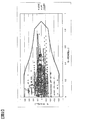
- FIG. 2 is a diagram illustrating an example of a motor usage frequency distribution (vehicle operating point) in various travel modes of the HEV vehicle.
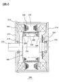
- FIG. 3 is a diagram showing an example of a PM motor used as a rotating electric machine 200 for driving an electric vehicle such as EV or HEV.
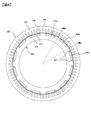
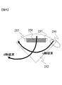
- FIG. 4 is a view showing a cross section of the stator 230 and the rotor 250.
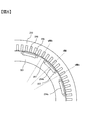
- FIG. 5 is an enlarged view of a part of the cross-sectional view shown in FIG.
- FIG. 5 is a diagram for explaining the principle of reluctance torque generation.
- FIG. 1 is a diagram showing a schematic configuration of a hybrid electric vehicle (HEV) equipped with a drive control device 600 of the present embodiment.
- FIG. 2 is a diagram illustrating an example of a motor usage frequency distribution (vehicle operating point) in various travel modes
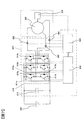
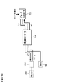
- FIG. 7 is a diagram showing an outline of a circuit configuration of the drive control device 600.
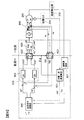
- FIG. 8 is a control block diagram for explaining vector control performed by the motor controller 620.
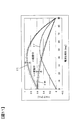
- FIG. 9 is a diagram for explaining a change in characteristics due to a temperature change of a neodymium magnet.
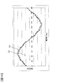
- FIG. 10 is a diagram illustrating a change in induced voltage caused by a temperature change of the permanent magnet.
- FIG. 11 is a diagram showing a change in motor output torque caused by a temperature change of the permanent magnet.
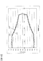
- FIG. 12 is a diagram showing a change in motor output characteristics at the maximum current caused by a temperature change of the permanent magnet.
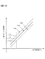
- FIG. 13 is a diagram showing the relationship between the torque command value ⁇ * and the actually generated torque value ⁇ .
- FIG. 14 is a diagram for explaining the first correction method.
- FIG. 15 is a diagram illustrating an example of a current map.
- FIG. 16 is a diagram illustrating current command values stored at the same operating point ( ⁇ *, ⁇ r) in the current maps 6252 to 6254.
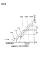
- FIG. 17 is a diagram in which the lines Tm0, TmH, and TmL of FIG. 16 are displayed on the ⁇ * - ⁇ coordinates.
- FIG. 18 is a diagram showing the relationship between the regenerative torque command value ⁇ * and the actual motor regenerative torque ⁇ at magnet temperatures Tm0, TmH, and TmL.
- FIG. 19 is a diagram showing the relationship between the corrected regenerative torque command value ⁇ * and the actual regenerative torque value ⁇ .
- FIG. 20 shows an example of the braking force distribution between the regenerative brake portion and the hydraulic brake portion during the regenerative cooperative brake operation.
- FIG. 21 is a diagram illustrating a procedure of regenerative cooperative brake operation.
- FIG. 22 is a diagram illustrating a case where the magnet temperature changes from the predetermined temperature Tm0 to the high temperature Tmh.
- FIG. 23 is a diagram illustrating a case where the magnet temperature changes from the predetermined temperature Tm0 to the low temperature TmL.
- FIG. 1 is a diagram showing a schematic configuration of a hybrid electric vehicle (HEV) equipped with a drive control device 600 of the present embodiment.
- An engine 120 and a rotating electric machine 200 connected coaxially with the engine 120 are mounted on the front portion of the vehicle.
- the rear wheel 110 is driven by the driving force of the engine 120 and the rotating electric machine 200 via the transmission 130 and the differential gear 132.
- the HEV 100 in FIG. 1 is a so-called FR type, but the present invention can also be applied to an FF type that drives the front wheels.
- a battery 180 is mounted on the vehicle, and when a driving force by the rotating electrical machine 200 is required, direct current power is supplied from the battery 180 to the driving device 600 of the rotating electrical machine 200, and the driving device 600 supplies 3 to the rotating electrical machine 200.
- Supply phase AC power is supplied.
- the three-phase AC power generated by the rotating electrical machine 200 is converted into DC power by the power converter 600, and the DC power is supplied to the battery 180 to charge the battery 180.
- the battery control unit 710 controls and monitors the battery 180.
- the vehicle controller 700 controls the entire vehicle. Drive device 600 and battery control unit 710 operate in accordance with a command from vehicle controller 700.
- the high voltage battery 180 is configured by connecting a plurality of secondary batteries such as lithium ion batteries or nickel metal hydride batteries in series and parallel. High voltage DC power is supplied from the battery 180 to the driving device 600.
- the rotating electrical machine 200 during the traveling of the vehicle repeats the power running operation and the regenerative operation.
- FIG. 2 is a diagram showing an example of a motor usage frequency distribution (vehicle operating point) in a travel mode such as JC08, LA4, EUDC of an EV vehicle on an NT map.
- Power running operation is performed in a region where the motor torque is positive, and regenerative operation is performed in a portion where the motor torque is negative.
- the motor torque can usually be output in the area surrounded by the solid line shown in FIG. 2, and therefore the operation in the running mode such as JC08, LA4, EUDC is the operation of each mode shown in FIG. This is done as an example of a point.
- FIG. 3 is a diagram showing an example of a PM motor used as a rotating electric machine 200 for driving an electric vehicle such as EV or HEV.
- a rotating electrical machine 200 shown in FIG. 3 includes a 12-pole rotor and a 72-slot distributed winding stator.
- a stator 230 is held inside the housing 212 of the rotating electrical machine 200.
- the stator 230 includes a stator core 232 and a stator winding 238.
- Inside the stator core 232 a rotor 250 is rotatably held through a gap 222.
- the rotor 250 includes a rotor core 252, a permanent magnet 254, and a non-magnetic contact plate 226, and is fixed to the shaft 218.
- the housing 212 has a pair of end brackets 214 provided with bearings 216, and the shaft 218 is rotatably held by these bearings 216.
- the shaft 218 is provided with a rotation sensor (resolver) 224 that detects the position and rotation speed of the pole of the rotor 250.
- the output from the rotation sensor 224 is taken into a motor controller 620 described later.
- FIG. 4 is a view showing a cross section of the stator 230 and the rotor 250.
- FIG. 5 is an enlarged view of a part of the cross-sectional view shown in FIG.
- the slot 240 is provided with a stator winding 238 and a slot insulating material that insulates the stator winding 238 from the stator core 232.
- distributed winding is used in which a plurality of phase windings of u phase, v phase, and w phase constituting the stator winding 238 are distributed and mounted in a plurality of slots.
- the distributed winding is a winding method in which the phase windings are wound around the stator core 232 so that the phase windings are accommodated in two slots that are spaced apart from each other across the plurality of slots 240.
- the magnetic flux distribution of each phase generated by the stator is close to a sine wave, and reluctance torque is easily obtained.
- the present invention achieves the same effect regardless of how the stator winding 238 is wound.
- the number of slots of the stator is smaller than the number of slots shown in FIG.
- a plurality of magnet insertion holes 310 are formed in the core 301 of the rotor core 252.
- a rectangular permanent magnet 254 (254a, 254b) is embedded in each magnet insertion hole 310 and fixed with an adhesive or the like.
- the permanent magnets 254a and 254b act as field poles of the rotor 250, and the permanent magnets 254a and 254b having different magnetization directions are alternately arranged in the circumferential direction.
- the circumferential width of the magnet insertion hole 310 is set to be larger than the circumferential width of the permanent magnets 254a and 254b, and magnetic gaps 257 are formed on both sides of the permanent magnets 254a and 254b.
- the magnetic gap 257 may be embedded with an adhesive, or may be solidified integrally with the permanent magnets 254a and 254b with a molding resin.
- the magnetic air gap 257 is provided to reduce cogging torque.
- FIG. 6 is a diagram for explaining the principle of reluctance torque generation.
- the axis through which the magnetic flux passes through the center of the magnet is called the d-axis
- the axis through which the magnetic flux flows from one pole to another between the poles is called the q-axis.
- the iron core portion at the center between the magnets is called an auxiliary salient pole portion 259. Since the magnetic permeability of the permanent magnet 254 provided in the rotor 250 is substantially the same as that of air, when viewed from the stator side, the d-axis part is magnetically concave, the resistance is large, and the q-axis part is magnetic. It is convex and has low resistance.
- the core part of the q-axis part is called a salient pole.
- the reluctance torque is generated by a difference in the ease of passing the magnetic flux between the d-axis and the q-axis, that is, a difference in magnetic resistance.
- FIG. 7 is a diagram showing an outline of a circuit configuration of the drive control device 600, and shows the battery 180, the drive control device 600, and the rotating electrical machine 200.
- the drive control device 600 includes an inverter 610 for driving the rotating electrical machine 200, a driver 650 for driving and controlling the inverter 610, a motor controller 620 for controlling the driver 650, and a smoothing capacitor 615.
- the inverter 610 includes power modules 610a, 610b, and 610c. Each of the power modules 610a to 610c outputs a current of each phase U, V, W of three-phase AC output.
- the power modules 610a to 610c are composed of power semiconductor elements 611a and 611b, respectively.
- IGBTs Insulated Gate Bipolar Transistors
- MOS-FETs complementary metal-oxide-se-S-FETs
- each power module 610a to 610c includes an IGBT 611a and a free wheeling diode 612a on the positive electrode side (upper arm side), and an IGBT 611b and a free wheeling diode 612b on the negative electrode side (lower arm side). ing.
- the same power semiconductor elements are used for the power semiconductor elements 611a and 611b, and are collectively referred to as the power semiconductor elements 611.
- Free-wheeling diodes 612a and 612b are also collectively referred to as free-wheeling diodes 612.
- the driver 650 is driven and controlled based on a control signal from the motor controller 620, and controls the switching operation of the power semiconductor elements 611a and 611b of the power modules 610a to 610c.
- the DC power from the battery 180 is supplied to the positive and negative DC terminals of the power modules 610a to 610c constituting the inverter 610 of the drive control device 600.
- the drive control device 600 controls the switching operation of the power semiconductor element 611 to convert the supplied DC power into three-phase AC power and supply it to the rotating electrical machine 200. By such a switching operation of the power semiconductor element 611, a three-phase alternating current is supplied to the rotating electrical machine 200, and the rotating electrical machine 200 is driven as an electric motor.
- the rotating electrical machine 200 is operated as a generator.
- the rotor of the rotating electrical machine 200 is rotationally driven with a rotational torque applied from the outside, and three-phase AC power is output from the stator winding of the rotating electrical machine 200.
- the output three-phase alternating current is converted into direct current by the operations of the power semiconductor elements 611a and 611b and the freewheeling diodes 612a and 612b, and is supplied to the battery 180 to charge the battery 180.
- a smoothing capacitor 615 is connected in parallel with the battery 180 between the battery 180 and the inverter 610. DC voltage pulsation (ripple) generated by the switching operation of the power semiconductor elements 611a and 611b is smoothed by the smoothing capacitor 615.
- the driver 650 constitutes a drive unit for controlling the corresponding inverter device 610.
- the driver 650 generates a gate drive signal for operating (turning on / off) the power semiconductor elements 611a and 611b based on a control signal (PWM signal) output from the motor controller 620 operating as a control unit.
- PWM signal control signal
- the driver 650 is provided with six integrated circuits that generate drive signals to be supplied to the gates of the upper and lower arms of each phase. From these integrated circuits, gate signals for driving the gates of the power semiconductor elements 611 of the power modules 610a to 610c are output.
- the PWM signal for controlling the driver 650 is generated by calculation in a microcomputer (not shown) provided in the motor controller 620.
- the motor controller 620 receives a torque command signal (torque command value ⁇ *) from a host controller (not shown), a sensor output of the current sensor 660, and a sensor output of a rotation sensor (resolver) 224 mounted on the rotating electrical machine 200. Is done.
- the motor controller 620 calculates a control value based on the torque command value and each sensor output, and outputs a PWM signal for generating a gate drive signal to the driver 650.
- Each power semiconductor element 611 of each of the power modules 610a to 610c performs a switching operation based on the gate signal, and converts DC power supplied from the battery 180 into three-phase AC power.
- This three-phase AC power is supplied to the stator winding 238 and a rotating magnetic field is generated in the stator 230.
- the frequency of the three-phase alternating current is controlled based on the detected value of the resolver 224, and the phase of the three-phase alternating current with respect to the rotor 250 is also controlled based on the detected value of the resolver 224.
- FIG. 8 is a control block diagram for explaining vector control performed by the motor controller 620.
- the motor controller 620 includes a detection value of the resolver 224 and a detection value of the temperature detection unit 228 (detected by attaching a temperature sensor such as a thermocouple to the magnet, estimated from the applied voltage and current, estimated from the temperature of other parts, etc.). Entered.
- the temperature calculation unit 627 calculates the magnet temperature Tm from the detection value of the temperature detection unit 228.
- the temperature detection unit 228 is means for directly or indirectly detecting the temperature of the permanent magnet 254 provided in the rotor 250 (see FIG. 4) of the rotating electrical machine 200.
- the temperature detecting unit 228 is a stator core 232 of the rotating electrical machine 200.
- the temperature detected by the temperature sensor for detecting the temperature of the stator winding 238 is used as the indirectly detected magnet temperature.
- the relationship between the temperature of the stator core 232 and the stator winding 238 and the magnet temperature is obtained by actual measurement, and the magnet temperature is estimated from the temperature detected by the temperature sensor and its correlation.
- the position speed calculation unit 621 of the motor controller 620 calculates the magnetic pole position ⁇ d and the angular speed ⁇ r of the rotor (not shown) of the rotating electrical machine 200 based on the detection value of the resolver 224.
- the magnetic pole position ⁇ d is a two-phase / three-phase converter 622 that converts the dq-axis (two-phase) system to the UVW (three-phase) system, and three that converts the UVW (three-phase) system to the dq-axis (two-phase) system. Each is input to the phase-to-phase converter 623 and used for conversion calculation in each.
- the three-phase to two-phase converter 623 converts the current values Iu, Iv, and Iw input from the current sensor 660 into dq-axis currents Idc and Iqc based on the magnetic pole position ⁇ d input from the position / velocity calculator 621. To do.
- the converted dq-axis currents Idc and Iqc are fed back (negative feedback) to the d-axis current command Id * and the q-axis current command Iq * before being input to the current control unit 624.
- the current command calculation unit 625 calculates a d-axis current command Id * and a q-axis current command Iq * to the rotating electrical machine 200.
- the d-axis current command Id * and the q-axis current command Iq * are calculated based on the angular velocity ⁇ r input from the position / speed calculator 621 and the torque command ⁇ * input from the host controller.
- the d-axis current command Id * and the q-axis current command Iq * are calculated in consideration of the magnet temperature Tm in addition to the torque command ⁇ * and the angular velocity ⁇ r.
- the d-axis current command Id * and the q-axis current command Iq * output from the current command calculation unit 625 are input to the current control unit 624 after the dq-axis currents Idc and Iqc are fed back (negative feedback) as described above. Is done.
- the current control unit 624 converts the input dq-axis current command into voltage command values (d-axis voltage command Vdc *, q-axis voltage command Vqc *), and outputs them to the two-phase / three-phase conversion unit 622. .
- the two-phase / three-phase converter 622 converts the d-axis voltage command Vdc * and the q-axis voltage command Vqc * into the three-phase voltage commands Vu *, Vv *, and Vw * based on the magnetic pole position ⁇ d.
- gate control signal calculation unit 626 Based on the three-phase voltage commands Vu *, Vv *, and Vw *, gate control signal calculation unit 626 generates a control signal for conducting or blocking power semiconductor element 611 provided in inverter 610.
- the vector control performs feedback of the detected coil current of each phase, and when the conditions are the same torque and the same rotation speed, the position of the magnetic flux generated by the current with respect to the magnetic pole position of the rotor Is a method for performing constant control, and the time change of the current waveform of each phase of the stator coil that performs torque control basically becomes a sine wave.
- the characteristics of the permanent magnet change with temperature as shown in FIG. 9, and when the temperature rises by 100 ° C., the magnetic flux density is reduced by about 10%.
- the magnetic flux generated by the permanent magnet fluctuates in the range of B0 at low rotation (no field weakening) that does not require field weakening, depending on temperature changes in the environment or operating state of the rotating electrical machine 200.
- the magnetic flux generated by the permanent magnet at a high speed that requires a field weakening fluctuates in the range of B1 (by the field weakening action).
- the operating point of the permanent magnet is used in a demagnetizing field that does not exceed the knick point to prevent irreversible demagnetization.
- the induced voltage in the stator winding 238 is proportional to the differential value of the magnetic flux linked to the stator winding 238 ( ⁇ d ⁇ / dt, ⁇ is the coil linkage magnetic flux). Therefore, as shown in FIG. 10, if the permanent magnet 254 has a high temperature TmH, the induced voltage decreases as shown by a curve L1, and if the permanent magnet 254 has a low temperature TmL, the induced voltage increases as shown by a curve L2.
- a curve L0 indicates the induced voltage at the reference temperature Tm0 (design temperature).
- the permanent magnet torque ⁇ m generated by the action of the magnetic flux and armature current of the permanent magnet 254 also decreases when the magnet temperature is high temperature TmH, and when the magnet temperature is low temperature TmL. To increase. As a result, the total torque ⁇ t combined with the reluctance torque ⁇ r also rises and falls according to changes in the permanent magnet torque ⁇ m.
- ⁇ t is expressed by the following equation (1).
- P is the number of pole pairs
- Id is d-axis current
- Iq is q-axis current
- Ld is d-axis inductance
- Lq is q-axis inductance.
- ⁇ is a coil interlinkage magnetic flux, and is expressed as ⁇ Bm ⁇ S, where S is the area of the surface perpendicular to the magnetization direction of the permanent magnet and Bm is the magnetic flux density of the permanent magnet.
- ⁇ t p ⁇ Iq + p (Ld-Lq) Id ⁇ Iq (1)
- the first term on the right side is the permanent magnet torque ⁇ m, and the second term is the reluctance torque ⁇ r.
- the output range of the rotating electric machine 200 changes as shown in FIG. 12 according to the temperature of the permanent magnet 254.
- Curve L01 shows the output limit when the magnet temperature is the reference temperature Tm0
- curve L11 shows the output limit when the magnet temperature is high temperature TmH
- curve L21 shows the case where the magnet temperature is low temperature TmL. Indicates the output limit.
- the TN operating point is the same. Due to the temperature dependence of the magnetic flux density of the permanent magnet 254, the actual torque value of the rotating electrical machine 200 for the same torque command varies depending on the temperature.
- FIG. 13 is a diagram showing the relationship between the torque command value ⁇ * and the actually generated torque value ⁇ .
- the torque command ⁇ * and the rotation speed N are the same, so the same current command values Id * and Iq * are obtained from the current command calculation unit 625 (see FIG. 8). Is output. Since the inverter is current controlled, a PWM switching operation is performed so as to generate a current value according to the current command value. However, as described above, the permanent magnet 254 has a smaller magnetic flux density as the temperature is higher.
- the generated torque varies depending on the temperature of the permanent magnet 254 of the rotating electrical machine 200. It is not preferable as a vehicle.
- the motor torque is greater than the torque command value ⁇ * and is accelerated more than the driver's intention, and the same rotation If it is a number, the amount of power is more than necessary because the torque is large.
- the motor torque is smaller than the torque command value ⁇ *, does not accelerate more than the driver's intention, and the torque is small at the same rotational speed. I don't get the power I need.
- the braking force intended by the driver cannot be obtained because the regenerative torque is small. Furthermore, since the regenerative energy is less than the command value, the travel distance is shortened.
- the current command values Id * and Iq generated from the torque command value ⁇ * with respect to the input torque command value ⁇ *. * was corrected according to the magnet temperature of the rotational potential 200. As a result, it is possible to generate torque according to the torque command value without depending on the temperature of the permanent magnet 254. Below, the correction method is demonstrated.
- FIG. 14 is a diagram for explaining the first correction method.
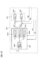
- FIG. 14 shows a current command calculation unit 625 and a current control unit 624 of the motor controller 620.
- the current command values Id * and Iq * are generated by switching the current map to be referred to according to the permanent magnet temperature Tm for the same torque command value ⁇ *.
- the current command calculation unit 625 includes a current map 6252 when the magnet temperature is the reference temperature Tm0, a current map 6253 when the magnet temperature is the high temperature TmH, and a current when the magnet temperature is the low temperature TmL. And a map 6254.
- the current map selection unit 6251 selects the current map 6252 when the magnet temperature Tm is the reference temperature Tm0, selects the current map 6253 when the magnet temperature Tm is TmH, and the magnet temperature Tm is TmL. In this case, the current map 6254 is selected. Then, the current command calculation unit 625 generates a current command value by searching the current command value from the selected current map based on the torque command value ⁇ * and the angular velocity ⁇ r. When the magnet temperature Tm is between Tm0 and TmH or between Tm0 and TmL, the current command value is generated by interpolating each current map.
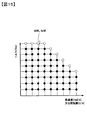
- FIG. 15 is a diagram illustrating an example of a current map.
- the horizontal axis represents the angular velocity ⁇ r (or rotation speed), and the vertical axis represents the torque command value ⁇ *.
- Each operating point is divided into a grid, and each operating point stores a d-axis current command value Id * and a q-axis current command value Iq * that are necessary to output a torque command value ⁇ * at an angular velocity ⁇ r. Yes.
- Current command values Id * and Iq * are not stored at the operating points indicated by white circles outside the operating points indicated by black circles. That is, the range indicated by the black circle is the operating range.
- the data between the operating points is calculated using linear interpolation or the like.
- the current maps 6252 to 6254 in the present embodiment are all current maps as shown in FIG. 15, but d-axis current commands Id *, stored at the same operating point ( ⁇ *, ⁇ r). Each q-axis current command Iq * is different.
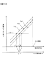
- FIG. 16 is a diagram for explaining current command values stored at the same operating point ( ⁇ *, ⁇ r) of the current maps 6252 to 6254.
- Point B indicates the current command value at the same operating point ( ⁇ *, ⁇ r) of the current map 6253.
- the current command value B is a current command value at which the actual motor torque ⁇ becomes ⁇ 0 when the magnet temperature Tm is the high temperature TmH.
- Point C indicates the current command value at the same operating point ( ⁇ *, ⁇ r) of the current map 6254.
- the current command value C is a current command value at which the actual motor torque ⁇ becomes ⁇ 0 when the magnet temperature Tm is a low temperature TmL.
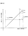
- FIG. 17 is a diagram corresponding to FIG. 13 in which the horizontal axis in FIG. 16 is replaced with a torque command ⁇ *.
- the current command values A, B, and C are all torque command values ⁇ *
- the three straight lines in FIG. 16 overlap to form one straight line.
- the torque command value ⁇ * corresponding to the output limit determined by the current output limit range of the inverter shown in FIG. 16 is lower at the high temperature TmH than at the reference temperature Tm, and at the low temperature TmL. Will increase. Therefore, as shown in FIG. 17, there are a portion where three straight lines overlap (torque constant control range) and a region (torque increase range) larger than the torque command value ⁇ * corresponding to the output limit in the case of high temperature TmH. Arise.
- the motor torque ⁇ can be generated as commanded at any magnet temperature of TmL, Tm0, and TmH.
- the torque command value ⁇ * corresponding to the output restriction corresponds to the curves L01, L11, L21 shown in FIG.
- the motor torque ⁇ that can be actually generated is raised to the curve L21.
- the current map at the reference temperature Tm0 assuming that the current command value is stored at the operating point indicated by the black circle, the current map at the low temperature TmL The current command value is also stored at the operating point of the white circle. Therefore, when the magnet temperature is lower than the reference temperature Tm0 (TML), a torque larger than usual is generated by raising the upper limit of the torque command value ⁇ * from the vehicle side within the current output limit range of the inverter. It becomes possible to do.
- the number of current maps that are further added to the reference temperature current map is not limited to the two described above, and may be more than that. If there is no current map that matches the magnet temperature Tm, the magnet temperature Tm The current command value is obtained by interpolating the current map closest to the high temperature and the current map closest to the magnet temperature Tm.
- the coil interlinkage magnetic flux ⁇ included in the torque equation and voltage equations (1) to (5) of the rotating electrical machine 200 is set to the temperature in order to cope with the temperature change of the magnetic flux density of the permanent magnet 254. It was handled as a function of. With such a configuration, it is possible to generate motor torque according to the torque command value ⁇ * from the host controller regardless of the magnet temperature.
- the torque ⁇ and the mechanical output Pout of the rotating electrical machine 200 can be expressed by the above-described formula (1) and the following formula (2).
- P is the number of pole pairs
- Id is a d-axis current
- Iq is a q-axis current
- Ld is a d-axis inductance
- Lq is a q-axis inductance
- ⁇ m is a mechanical angular velocity.
- ⁇ is a coil interlinkage magnetic flux, and is expressed as ⁇ Bm ⁇ S, where S is the area of the surface perpendicular to the magnetization direction of the permanent magnet and Bm is the magnetic flux density of the permanent magnet.
- ⁇ p ⁇ Iq + p (Ld-Lq) Id ⁇ Iq (1)
- Pout ⁇ m ⁇ ⁇ (2)
- V ⁇ (Vd ⁇ 2 + Vq ⁇ 2) ...
- Vd R ⁇ Id - ⁇ ⁇ Lq ⁇ Iq (4)
- Vq R ⁇ Iq + ⁇ ⁇ Ld ⁇ Id + ⁇ ⁇ ⁇ (5)
- the coil linkage magnetic flux ⁇ is an amount that the magnetic flux generated by the permanent magnet 254 passes through the armature coil, and the magnetic flux generated by the permanent magnet 254 is on a plane perpendicular to the magnetization direction of the permanent magnet 254. It is determined by the product of area S and magnetic flux density Bm.
- the magnetic flux density Bm which is a permanent magnet property, has temperature dependence as shown in FIG.
- the torque equation and voltage By making the coil linkage magnetic flux ⁇ included in the equation a function of the temperature of the permanent magnet, it becomes possible to control the driving force in consideration of the temperature dependence of the permanent magnet 254.
- the coil linkage magnetic flux ⁇ (Wb) as a function of the temperature T is obtained in advance by actual measurement or the like and stored in a storage unit (not shown) of the current command calculation unit 625.
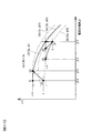
- FIG. 22 is a diagram illustrating a case where the magnet temperature changes from the predetermined temperature Tm0 to the high temperature TmH.
- a line L0 (Ia, ⁇ ) indicates the torque ⁇ (total torque ⁇ t) when the magnet temperature is Tm0.
- the rotating electric machine 200 is driven, for example, in a state (maximum torque control) as indicated by a point E on the line L0 (Ia, ⁇ ).
- the rotating electrical machine 200 is rotating at high speed and field weakening is being performed, the rotating electrical machine 200 is driven in a state where the current phase angle is slightly large as indicated by the point D of the line L0 (Ia, ⁇ ).
- the motor torque ⁇ is the torque command value. It becomes smaller than ⁇ *. That is, after the temperature change, the actually generated motor torque moves from the points D and E of the motor torque ⁇ * to the points D1 and E1 of the motor torque ⁇ .
- lines Lh (Ia, ⁇ h), Lh (Ib, ⁇ h), and Lh (Ic, ⁇ h) indicated by broken lines are replaced with ⁇ h at high temperature in the above-described equation (1) ′.
- the torque ⁇ t is shown.
- Ia, Ib, and Ic are current values (current amplitudes) and have a relationship of Ia ⁇ Ib ⁇ Ic.
- the line Lh (Ia, ⁇ h) may be moved to the point D2 by changing from ⁇ 1 to ⁇ 2. Further, since there is a line between the line Lh (Ia, ⁇ h) and the line Lh (Ib, ⁇ h), the current amplitude and the current phase angle may be changed and moved to the point D3. In either case, the motor torque according to the torque command value can be generated. Furthermore, high efficiency can be achieved by selecting a current command value that minimizes the current amplitude.
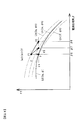
- FIG. 23 is a diagram illustrating a case where the magnet temperature changes from the predetermined temperature Tm0 to the low temperature TmL.
- the magnet temperature is changed to the low temperature TmL, if the current map of the reference temperature Tm0 is used as it is, ⁇ > ⁇ *. Therefore, after the temperature change, the actually generated motor torque moves from the point F of the motor torque ⁇ * to the point F1 of the motor torque ⁇ .
- point D in FIG. 22 and point F in FIG. 23 are regions where field-weakening control is performed. Therefore, in setting the current command value at the operating point in the high rotation range when creating the current map of the high temperature TmH and the low temperature TmL, the field weakening control is performed when the torque of the rotating electrical machine 200 is matched with the torque command value ⁇ *. The current amplitude and the current phase are changed so as to satisfy the voltage limitation due to.
- the current command value is corrected as described above. Also when calculating using the torque equation and voltage equation, the current command value is calculated in the manner of correction as described above.
- the motor operation of the rotating electrical machine 200 during powering has been described, but the same applies to the regenerative braking operation. That is, with respect to the regenerative torque command value ⁇ *, the motor regenerative torque at the reference temperature Tm0, at the high temperature TmH, and at the low temperature TmL is as shown in FIG. 18, and the situation is exactly the same as that shown in FIG. . Therefore, when the magnet temperature Tm is higher than the reference temperature Tm0 with respect to the regenerative torque designation value ⁇ * input from the vehicle controller 700 (Tm> Tm0), the actually obtained regenerative torque is the regenerative torque designation value. It becomes smaller than ⁇ * and the energy that can be recovered by the regenerative brake is reduced.
- FIG. 19 is a diagram showing the relationship between the corrected regenerative torque command value ⁇ * and the actual regenerative torque value ⁇ . The relationship is exactly the same as that shown in FIG. 17, and within the constant torque control range of FIG. 19, regenerative torque according to the regenerative torque command value ⁇ * can be generated regardless of the magnet temperature Tm.
- FIG. 20 shows an example of the braking force distribution between the regenerative brake and the hydraulic brake during the regenerative cooperative brake operation.
- the upper graph in FIG. 20 shows braking force distribution, and the lower graph shows how the vehicle speed changes. In the example shown in FIG. 20, it showed about the case where required motive power is constant.
- the amount of regenerative torque varies up and down as shown by the broken line with respect to the line shown by the solid line (at the reference temperature Tm0) according to the change width of the magnet temperature Tm.
- the sum of the regenerative brake and hydraulic brake is controlled to be equal to the required braking force, so that the hydraulic brake also changes as indicated by the alternate long and short dash line according to the temperature change of the regenerative brake. become.
- the correction based on the magnet temperature Tm as shown in FIG. 19 is performed by using the above-described method of switching the current map or the method of creating the current command value from the torque equation and the voltage equation, and this is indicated by the solid line in FIG.
- Such a regenerative braking force can be generated.
- stable regenerative cooperative brake control can be performed.
- FIG. 21 is a diagram showing a procedure of regenerative cooperative brake operation.
- the brake controller 701 calculates the total braking force based on the brake pressing force, and passes the calculation result (a) to the vehicle controller 700.
- the vehicle controller 700 distributes the total braking force between the hydraulic braking force and the regenerative braking force.
- the vehicle controller 700 inputs a distributed hydraulic brake force command to the brake controller 701, and inputs a regenerative torque command value ⁇ * corresponding to the regenerative brake force to the motor controller 620 of the drive control device 600.
- the hydraulic brake rises and generates a braking force with respect to the required braking force. Thereafter, a part of the necessary braking force is gradually distributed to the regenerative braking force, and the regenerative braking force is increased to the distribution determined by the vehicle controller 700 and the hydraulic braking force is decreased. By adjusting the distribution of the braking force in this way, the regenerative cooperative operation can be performed smoothly.
- the regenerative torque command value ⁇ * may be outside the NT curve of the rotating electrical machine 200 due to the influence of the battery voltage, etc., so the motor controller 620 determines the current value actually flowing through the rotating electrical machine 200. Based on the above, the actual regenerative torque ⁇ is operated, and the vehicle controller 700 is answered. The vehicle controller 700 adjusts the brake force distribution again and performs the regenerative cooperative brake operation. The vehicle controller 700 transmits to the brake controller 701 a hydraulic brake component (b) obtained by subtracting the regenerative brake component based on the actual regenerative torque ⁇ from the necessary braking force.
- the drive control device 600 outputs an upper limit value (c) of the torque that can be generated according to the magnet temperature to the vehicle controller 700.
- the drive control device 600 performs vector control on the current of the rotating electrical machine 200 in which the permanent magnet 254 is provided on the rotor 250 based on the torque command value ⁇ * from the vehicle controller 700, and rotates using the battery 180 as a power source. Driving of the electric machine 200 and regenerative charging of the battery 180 by the rotating electric machine 200 are performed. Then, the drive control device 600 uses the same torque so that the temperature calculator 627 that calculates the magnet temperature Tm based on the detection value of the temperature detector 228 and the torque ⁇ of the rotating electrical machine 200 coincide with the torque command value ⁇ *. A current command calculation unit 625 that generates different current command values Id * and Iq * according to the magnet temperature Tm with respect to the command value ⁇ *.
- the current command values Id * and Iq * are generated accordingly. Therefore, the torque ⁇ corresponding to the torque command value ⁇ * can be generated by the rotating electrical machine 200, and appropriate control according to the magnet temperature can be performed. Further, even when the magnet temperature Tm is low, the torque more than necessary than the torque command value is not generated unlike the conventional case, so that the energy stored in the battery 180 is not used more than necessary. The cruising distance can be prevented from decreasing. In this case, since the current value is smaller than that in the prior art, the copper loss can be reduced.
- the current command calculation unit 625 has at least a current amplitude and a current value in the case of a high temperature TmH or a low temperature TmL than the predetermined temperature Tm0. By correcting one of them, the torque ⁇ of the rotating electrical machine 200 is made to coincide with the torque command value ⁇ *, and in the region where the rotational speed of the rotating electrical machine 200 requires field weakening control, the current limit is satisfied so that the voltage limit by the field weakening control is satisfied. The amplitude and current phase are corrected to make the torque ⁇ of the rotating electrical machine 200 coincide with the torque command value ⁇ *.
- the induced voltage is low, so that the d-axis current for field weakening can be reduced.
- the torque is reduced, it is necessary to increase the q-axis current, and the current amplitude and the current phase are adjusted so as to satisfy the voltage limit and the torque.
- the temperature of the permanent magnet is lower than the predetermined temperature, the induced voltage is high, and therefore it is necessary to increase the d-axis current.
- the q-axis current can be reduced. Therefore, the current amplitude and the current phase are adjusted by increasing the d-axis current and decreasing the q-axis current so as to satisfy the voltage limit and the torque.
- the vehicle controller 700 controls an electric vehicle including a regenerative cooperative brake control device (700) that performs braking control using a hydraulic brake and a regenerative brake.
- a regenerative cooperative brake control device 700
- Different current command values corresponding to the magnet temperature Tm are generated for the same torque command value so that the torque ⁇ of the rotating electrical machine 200 during the regenerative cooperative braking operation matches the torque command value ⁇ *.
- a regenerative braking force according to the command value can be obtained and an appropriate braking operation can be performed.
- the current command calculation unit 625 outputs a torque limit value that can be generated by the rotating electrical machine 200 to the vehicle controller 700 that generates the torque command value ⁇ * according to the magnet temperature Tm.
- the torque that can be output increases as compared with the reference temperature, so that the output capability of the motor can be utilized to the maximum.
- it can prevent that the energy which can be collect
- the drive control device 600 further includes a position / speed calculation unit 621 for calculating the rotation speed ⁇ of the rotating electrical machine 200, and the current command calculation unit 625 includes a plurality of magnet temperatures Tm0, Based on a plurality of current maps 6252 to 6254 which are provided in association with TmH and TmL and indicate the correlation between the rotational speed ⁇ and torque ⁇ of the rotating electrical machine 200 and the current command value, and a temperature calculation unit 627 based on a signal from the temperature detection unit 228 And a current map selection unit 6251 for selecting one of the plurality of current maps 6252 to 6254 based on the magnet temperature Tm calculated by the current map selection unit 6251.
- the current command value is determined based on the current map, the torque command value ⁇ *, and the rotation speed ⁇ calculated by the rotation speed calculation unit 621.
- the method includes a rotation speed calculation unit 621 that calculates the rotation speed ⁇ of the rotating electrical machine 200, and a current command calculation unit 625 is based on the voltage equation and torque equation using the coil linkage magnetic flux ⁇ that changes depending on the magnet temperature Tm as a parameter, the torque command value ⁇ *, and the rotational speed ⁇ calculated by the rotational speed calculation unit 621. To determine the current command value.
- the electric vehicle drive system includes a rotating electrical machine 200 in which a permanent magnet 254 is provided on a rotor 250, the drive control device 600 described above, a brake controller 701, and regenerative coordination using hydraulic brake force and regenerative brake force.
- a vehicle controller 700 for calculating a hydraulic brake command value and a torque command value during a braking operation.
- the vehicle controller 700 outputs the torque limit value to the current command calculation unit 625 as the torque command value ⁇ * during the regenerative cooperative brake operation. Therefore, when the required braking force is larger than the regenerative braking force, the regenerative power that can be returned to the battery 180 can be increased by allocating the upper limit of the regenerative braking force when determining the braking force distribution. .
- 180 battery, 200: rotating electric machine, 228: temperature detection unit, 230: stator, 250: rotor, 254: permanent magnet, 600: drive control device, 621: position speed calculation unit, 625: current command calculation unit, 627: Temperature calculation unit, 700: Vehicle controller, 701: Brake controller, 710: Battery control unit, 6251: Current map selection unit, 6252-6254: Current map
Landscapes
- Engineering & Computer Science (AREA)
- Power Engineering (AREA)
- Transportation (AREA)
- Mechanical Engineering (AREA)
- Life Sciences & Earth Sciences (AREA)
- Sustainable Development (AREA)
- Sustainable Energy (AREA)
- Physics & Mathematics (AREA)
- Electromagnetism (AREA)
- Control Of Ac Motors In General (AREA)
- Control Of Motors That Do Not Use Commutators (AREA)
Abstract
回転子に設けられた永久磁石の磁石温度によらず、トルク指令値通りのトルクを回転電機に発生させることができる、回転電機の駆動制御装置の提供するために、駆動制御装置600は、回転子に永久磁石が設けられた回転電機200の電流を車両コントローラからのトルク指令値τ*に基づいてベクトル制御し、バッテリ180を電源とする回転電機200の駆動および回転電機200によるバッテリ180の回生充電を行う。そして、駆動制御装置600は、温度検出部228の検出値に基づいて磁石温度Tmを算出する温度演算部627と、回転電機200のトルクτがトルク指令値τ*と一致するように、同一トルク指令値τ*に対して磁石温度Tmに応じた異なる電流指令値Id*,Iq*を生成する電流指令演算部625と、を備える。
Description
本発明は、回転電機の駆動制御装置、およびその駆動制御装置を備える電動車両駆動システムに関する。
電気自動車(EV)やハイブリッド自動車(HEV)に用いられる駆動用回転電機(モータ)には大出力および高トルク応答が求められるため、強力なエネルギーを保持する希土類の焼結磁石を用いた永久磁石式回転電機(PMモータ)を3相インバータで駆動する方式が一般に用いられている。駆動用モータには、永久磁石モータの内でも、低速大トルク、かつ、広範囲な回転速度領域という要求を満たすことができる埋込み磁石式モータ(IPM)が利用されている。
駆動用主機となるモータにおいて、特に、電気自動車での使用を考えた場合、市街地走行ではモータ動作点は比較的、小さい負荷点に集中し、追越や合流時の加速および高速道路の走行では高回転側で高出力が必要となり、さらに勾配の急な登坂では低速で大トルクが必要となる。このように電気自動車用のモータでは走行状態に応じてモータ動作点は頻繁に変化し、モータの発熱量も変化するため、モータは温度変化を続ける。モータ温度が変化すると永久磁石の磁束の変化が起りモータのトルクと機械出力が変化する。
このようなモータ温度変化による永久磁石の不可逆減磁を防止するために、PMモータの永久磁石の温度を検出し、永久磁石が高温の場合に電流を小さくする手法が提案されている(例えば、特許文献1参照)。
しかしながら、従来のモータ駆動の方法では、モータのトルク制御を行う電流指令値は、モータ温度によらず各動作点で一意的に決まっていた。そのため、モータに入っている永久磁石の温度が基準値よりも低ければ出力トルクは設計値よりも大きくなり、また、永久磁石の温度が基準値よりも高ければ出力トルクは小さくなる。そのため、トルクの増減に伴って機械出力も必要な値とならず、必要量よりも多かったり、少なかったりする。
請求項1の発明は、回転子に永久磁石が設けられた回転電機の電流をトルク指令値に基づいてベクトル制御し、バッテリを電源とする回転電機の駆動および回転電機によるバッテリの回生充電を行う回転電機駆動制御装置において、回転電機に設けられた温度検出部の検出信号に基づいて、永久磁石の温度を算出する温度演算部と、回転電機のトルクがトルク指令値と一致するように、同一トルク指令値に対して磁石温度に応じた異なる電流指令値を生成する電流指令演算部と、を備えることを特徴とする。
請求項7の発明は、回転子に永久磁石が設けられた回転電機と、請求項4に記載の回転電機駆動制御装置と、油圧ブレーキ制御装置と、油圧ブレーキ力および回生ブレーキ力を用いた回生協調ブレーキ動作時の油圧ブレーキ指令値およびトルク指令値を演算する上位制御装置と、を備える電動車両駆動システムにおいて、車両制御部は、磁石温度が所定温度よりも低い低温時には、トルク限界値を回生協調ブレーキ動作時のトルク指令値として電流指令演算部に出力することを特徴とする。
請求項7の発明は、回転子に永久磁石が設けられた回転電機と、請求項4に記載の回転電機駆動制御装置と、油圧ブレーキ制御装置と、油圧ブレーキ力および回生ブレーキ力を用いた回生協調ブレーキ動作時の油圧ブレーキ指令値およびトルク指令値を演算する上位制御装置と、を備える電動車両駆動システムにおいて、車両制御部は、磁石温度が所定温度よりも低い低温時には、トルク限界値を回生協調ブレーキ動作時のトルク指令値として電流指令演算部に出力することを特徴とする。
本発明によれば、回転子に設けられた永久磁石の磁石温度によらず、トルク指令値通りのトルクを回転電機に発生させることができる。
以下、図を参照して本発明を実施するための形態について説明する。図1は、本実施の形態の駆動制御装置600を搭載したハイブリッド型電気自動車(HEV)の概略構成を示す図である。車両の前部には、エンジン120およびエンジン120と同軸に接続された回転電機200が搭載されている。変速機130とデファレンシャルギア132を介して、エンジン120および回転電機200の駆動力により後輪110が駆動される。なお、図1のHEV100はいわゆるFRタイプであるが、本発明は、前輪を駆動するFFタイプであっても適用できる。
車両にはバッテリ180が搭載されており、回転電機200による駆動力が必要な場合には、回転電機200の駆動装置600にバッテリ180から直流電力が供給され、駆動装置600は回転電機200に3相交流電力を供給する。HEV100の回生走行時には、回転電機200が発電した3相交流電力を電力変換装置600で直流電力に変換し、その直流電力をバッテリ180に供給してバッテリ180を充電する。バッテリ制御部710は、バッテリ180の制御や監視を行う。車両コントローラ700は車両全体の制御を行うものである。駆動装置600およびバッテリ制御部710は車両コントローラ700の指令により動作する。
高電圧のバッテリ180は、リチウムイオン電池あるいはニッケル水素電池などの2次電池が複数個直並列に接続されて構成される。高電圧の直流電力が、バッテリ180から駆動装置600に供給される。車両の走行時における回転電機200は、力行運転と回生運転を繰返している。
図2は、EV車両のJC08、LA4、EUDCなどの走行モードでのモータ使用頻度分布(車両動作点)の例をN-Tマップ上で示した図である。モータトルクが正の領域では力行運転が行われ、モータトルクが負の部分では回生運転が行われる。モータのトルクは、通常は図2に示す実線部分で囲まれた領域で出力可能であり、したがって、JC08、LA4、EUDCなどの走行モードでの動作は、図2上に示される各モードの動作点の例のように行われる。
図3は、EVやHEV等の電動車両駆動用の回転電機200として用いられるPMモータの一例を示す図である。図3に示す回転電機200は、12極の回転子と72スロットの分布巻き固定子とを備えている。回転電機200のハウジング212の内部には、固定子230が保持されている。固定子230は、固定子鉄心232と固定子巻線238とを備えている。固定子鉄心232の内側には、回転子250が空隙222を介して回転可能に保持されている。回転子250は、回転子鉄心252と永久磁石254と非磁性体のあて板226を備えており、シャフト218に固定されている。ハウジング212は軸受216が設けられた一対のエンドブラケット214を有しており、シャフト218はこれらの軸受216により回転自在に保持されている。
シャフト218には、回転子250の極の位置や回転速度を検出する回転センサ(レゾルバ)224が設けられている。この回転センサ224からの出力は、後述するモータコントローラ620に取り込まれる。
図4は、固定子230および回転子250の断面を示す図である。また、図5は、図4に示した断面図の一部を拡大して示したものである。固定子鉄心232の内周側には、多数のスロット240とティース236とが全周に渡って均等に配置されている。なお、図4では、スロットおよびティースの全てに符号を付すことはせず、代表して一部のティースとスロットにのみに符号を付した。また、図示は省略したが、スロット240内には、固定子巻線238と、その固定子巻線238と固定子鉄心232とを絶縁するスロット絶縁材とが設けられている。
図4に示す例では、固定子巻線238を構成するu相、v相、w相の複数の相巻線が複数のスロットに分布して装着される分布巻を採用している。分布巻とは、複数のスロット240を跨いで離間した2つのスロットに相巻線が収納されるように、相巻線が固定子鉄心232に巻かれる巻線方式である。分布巻では、固定子で生成される各相の磁束分布は正弦波状に近く、リラクタンストルクを得やすい。そのため、弱め界磁制御やリラクタンストルクを活用して、低回転速度だけでなく高回転速度までの広い回転数範囲についての制御が可能であり、電気自動車などのモータ特性を得るのに適している。
もちろん、集中巻を採用しても良く、本発明は、固定子巻線238の巻き方によらず同様の効果を奏する。なお、通常、集中巻の場合は、固定子のスロット数は図4に示すスロット数より少ない。
回転子鉄心252のコア301には、磁石挿入孔310が複数形成されている。各磁石挿入孔310には、矩形の永久磁石254(254a,254b)が埋め込まれ接着剤などで固定されている。永久磁石254a,254bは回転子250の界磁極として作用するものであり、着磁方向の異なる永久磁石254a,254bが周方向に交互に配置されている。磁石挿入孔310の円周方向の幅は、永久磁石254a,254bの円周方向の幅よりも大きく設定されており、永久磁石254a,254bの両側には磁気的空隙257が形成されている。この磁気的空隙257は接着剤を埋め込んでも良いし、成形樹脂で永久磁石254a,254bと一体に固めても良い。磁気的空隙257は、コギングトルク低減のために設けられたものである。
3相交流電流により回転磁界が固定子230に発生すると、この回転磁界が回転子250の永久磁石254a,254bに作用して磁石トルクが生じる。さらに、回転子250には、この磁石トルクに加えてリラクタンストルクが作用する。なお、回転電機200は、図4,5において、どちらの回転方向にも回転可能である。しかし、説明の都合上、以下では回転子250あるいは回転子鉄心252はこれらの図で反時計回りに回転するものとする。以下では、図3,4に示したPMモータを例に、本発明による駆動制御装置600の動作について説明する。
図6は、リラクタンストルクの発生原理を説明する図である。一般に、磁束が磁石中心を通る軸をd軸,磁束が磁石の極間から極間へ流れる軸をq軸と呼ぶ。このとき,磁石の極間中心にある鉄心部分を補助突極部259と呼ぶ。回転子250に設けられた永久磁石254の透磁率は空気とほぼ同じであるため、固定子側から見た場合、d軸部は磁気的に凹んでおり、抵抗が大きく、q軸部は磁気的に凸になっており、抵抗が小さい。そのため、q軸部の鉄心部分は突極と呼ばれる。リラクタンストルクは、このd軸とq軸の磁束の通り易さの差、すなわち、磁気抵抗の差によって生じる。
図7は、駆動制御装置600の回路構成の概略を示す図であり、バッテリ180,駆動制御装置600および回転電機200を示した。駆動制御装置600は、回転電機200を駆動するためのインバータ610と、インバータ610を駆動制御するドライバ650と、ドライバ650を制御するモータコントローラ620と、平滑コンデンサ615とを備えている。
インバータ610はパワーモジュール610a,610b,610cで構成されている。パワーモジュール610a~610cは、それぞれ3相の交流出力の各相U、V、Wの電流を出力する。パワーモジュール610a~610cは、それぞれパワー半導体素子611a、611bで構成されている。本実施の形態では、パワー半導体素子611a、611bとしてIGBT(Insulated Gate Bipoler Transistor)を使用しているが、必要な周波数や電圧に応じて他のパワー半導体素子(例えばMOS-FETなど)を用いてもよい。
図7に示す例では、各パワーモジュール610a~610cは、正極側(上アーム側)にIGBT611aとフリーホイリングダイオード612aを備え、負極側(下アーム側)にIGBT611bとフリーホイリングダイオード612bを備えている。なお、パワー半導体素子611a、611bには同じパワー半導体素子が用いられており、パワー半導体素子611と総称する。また、フリーホイリングダイオード612a、612bもフリーホイリングダイオード612と総称する。
駆動制御装置600において、ドライバ650は、モータコントローラ620からの制御信号に基づき駆動制御され、パワーモジュール610a~610cのそれぞれのパワー半導体素子611a、611bのスイッチング動作を制御する。バッテリ180からの直流電力は、駆動制御装置600のインバータ610を構成するパワーモジュール610a~610cの、それぞれの正極側および負極側の直流端子に供給される。駆動制御装置600は、パワー半導体素子611のスイッチング動作を制御することにより、供給された直流電力を3相交流電力に変換し回転電機200に供給する。このようなパワー半導体素子611のスイッチング動作により、回転電機200に3相交流電流が供給されて、回転電機200は電動機として駆動される。
一方、車両の回生動作時には、回転電機200は発電機として運転される。このとき、回転電機200の回転子が外部から加えられる回転トルクで回転駆動され、回転電機200の固定子巻線から3相交流電力が出力される。出力された3相交流電流は、パワー半導体素子611a、611bおよびフリーホイリングダイオード612a、612bの動作によって直流に変換されて、バッテリ180に供給されてバッテリ180が充電される。
バッテリ180とインバータ610の間には、平滑コンデンサ615がバッテリ180と並列に接続されている。パワー半導体素子611a、611bのスイッチング動作により発生する直流電圧の脈動(リップル)は、この平滑コンデンサ615により平滑される。
ドライバ650は対応するインバータ装置610を制御するための駆動部を構成している。ドライバ650は、制御部として動作するモータコントローラ620から出力された制御信号(PWM信号)に基づいて、パワー半導体素子611a、611bを動作(オン・オフ)させるためのゲート駆動信号を発生する。図示は省略するが、ドライバ650には、各相の各上下アームのゲートに供給する駆動信号を発生する集積回路が6個設けられている。これらの集積回路からは、各パワーモジュール610a~610cのそれぞれのパワー半導体素子611のゲートを駆動するゲート信号が出力される。
ドライバ650を制御するためのPWM信号は、モータコントローラ620に備えられたマイクロコンピュータ(不図示)での演算によって生成される。モータコントローラ620には、不図示の上位制御装置からのトルク指令信号(トルク指令値τ*)、電流センサ660のセンサ出力、回転電機200に搭載された回転センサ(レゾルバ)224のセンサ出力が入力される。モータコントローラ620はトルク指令値および各センサ出力に基づいて制御値を演算し、ドライバ650にゲート駆動信号を生成するためのPWM信号を出力する。
各パワーモジュール610a~610cのそれぞれのパワー半導体素子611は、ゲート信号に基づきスイッチング動作を行い、バッテリ180から供給される直流電力を3相交流電力に変換する。この3相交流電力は固定子巻線238に供給され、回転磁界が固定子230に発生する。3相交流電流の周波数はレゾルバ224の検出値に基づいて制御され、3相交流電流の回転子250に対する位相も同じくレゾルバ224の検出値に基づいて制御される。
図8は、モータコントローラ620で行われるベクトル制御を説明する制御ブロック図である。モータコントローラ620には、レゾルバ224の検出値および温度検出部228の検出値(熱電対等の温度センサを磁石に付けて検出、印加電圧と電流から推定、他の部分の温度から推定、など)が入力される。温度演算部627は、温度検出部228の検出値から磁石温度Tmを算出する。温度検出部228は、回転電機200の回転子250(図4参照)に設けられた永久磁石254の温度を直接または間接的に検出する手段であって、例えば、回転電機200の固定子鉄心232や固定子巻線238の温度を検出するための温度センサで検出された温度を、間接的に検出された磁石温度として利用する。例えば、固定子鉄心232や固定子巻線238の温度と磁石温度との関係を実測により求めておき、温度センサで検出された温度とその相関関係とから、磁石温度を推定する。
モータコントローラ620の位置速度演算部621は、レゾルバ224の検出値に基づいて回転電機200の回転子(不図示)の磁極位置θdおよび角速度ωrを算出する。磁極位置θdは、dq軸(2相)系からUVW(3相)系へ変換する2相-3相変換部622、およびUVW(3相)系からdq軸(2相)系へ変換する3相-2相変換部623にそれぞれ入力され、それぞれにおける変換計算に用いられる。3相-2相変換部623では、位置速度演算部621から入力された磁極位置θdに基づいて、電流センサ660からから入力された電流値Iu、Iv、Iwをdq軸電流Idc,Iqcに変換する。変換されたdq軸電流Idc,Iqcは、電流制御部624に入力される前のd軸電流指令Id*、q軸電流指令Iq*にフィードバック(負帰還)される。
電流指令演算部625では、回転電機200へのd軸電流指令Id*、q軸電流指令Iq*を演算される。従来、d軸電流指令Id*、q軸電流指令Iq*は、位置速度演算部621から入力された角速度ωrおよび上位制御装置から入力されるトルク指令τ*に基づいて演算される。しかし、本実施の形態では、後述するように、トルク指令τ*および角速度ωrに加えて磁石温度Tmも考慮してd軸電流指令Id*、q軸電流指令Iq*の演算が行われる。
電流指令演算部625から出力されたd軸電流指令Id*、q軸電流指令Iq*は、上述したようにdq軸電流Idc,Iqcがフィードバック(負帰還)された後、電流制御部624に入力される。電流制御部624は、入力されたdq軸電流指令を、電圧指令値(d軸電圧指令Vdc*、q軸電圧指令Vqc*)に変換し、それらを2相-3相変換部622に出力する。2相-3相変換部622は、磁極位置θdに基づいて、d軸電圧指令Vdc*、q軸電圧指令Vqc*を3相電圧指令Vu*、Vv*、Vw*に変換する。ゲート制御信号演算部626は、その3相電圧指令Vu*、Vv*、Vw*に基づいて、インバータ610に設けられたパワー半導体素子611を導通または遮断するための制御信号を生成する。
このように、ベクトル制御は、検出された各相のコイル電流のフィードバックを行うことにより、同一トルクで同一回転数という条件である場合、回転子の磁極位置に対して、電流が作る磁束の位置を一定にするような制御を行う手法であり、基本的にトルク制御を行う固定子コイルの各相の電流波形の時間変化は正弦波となる。
ところで、希土類であるネオジムを使用した永久磁石では、図9のように永久磁石の特性は温度によって変化し、温度が100℃上昇すると概ね10%の磁束密度低下を起こす。例えば、回転電機200の環境や運転状態における温度変化に応じて、弱め界磁の必要が無い低回転(弱め界磁が行われていない)では永久磁石が発生する磁束はB0の範囲で変動し、弱め界磁の必要な高回転では永久磁石が発生する磁束は(弱め界磁が作用して)B1の範囲で変動する。なお、永久磁石の動作点はクニック点を越えない範囲の減磁界で使用され、不可逆減磁を防止している。
固定子巻線238での誘起電圧は、固定子巻線238に鎖交する磁束の微分値に比例する(∝-dφ/dt、φはコイル鎖交磁束)。そのため、図10に示すように、永久磁石254が高温TmHであれば曲線L1のように誘起電圧は低下し、永久磁石254が低温TmLであれば曲線L2のように誘起電圧は増加する。なお、曲線L0は、基準温度Tm0(設計温度)における誘起電圧を示したものである。
同様にして、図11に示すように、永久磁石254の磁束と電機子電流の作用で発生する永久磁石トルクτmも、磁石温度が高温TmHであれば低下し、磁石温度が低温TmLであれば増加する。その結果、リラクタンストルクτrと合せた総トルクτtも、永久磁石トルクτmの変化に応じて上下する。
ここで、τtは次式(1)のように表される。式(1)において、Pは極対数、Idはd軸電流、Iqはq軸電流、Ldはd軸インダクタンス、Lqはq軸インダクタンスである。また、φはコイル鎖交磁束であって、永久磁石の磁化方向に垂直な面の面積をS、永久磁石の磁束密度をBmとすると、φ ∝Bm・Sのように表される。
τt = pφIq + p( Ld - Lq ) Id・Iq …(1)
τt = pφIq + p( Ld - Lq ) Id・Iq …(1)
d軸電流Idおよびq軸電流Iqを用いて表現した式(1)を、Id=-I・sinβ、Iq=I・cosβを用いて電流値(電流振幅)Iと位相角βを用いた表現に変形すると、式(1)’のようになる。なお、「^2」は2乗を表す。式(1)’において、右辺の第1項は永久磁石トルクτmであり、第2項はリラクタンストルクτrである。
τt = pφIq + p( Ld - Lq ) Id・Iq …(1)
= pφI・cosβ +{ p( Lq - Ld )/2}I^2・sinβ …(1)’
τt = pφIq + p( Ld - Lq ) Id・Iq …(1)
= pφI・cosβ +{ p( Lq - Ld )/2}I^2・sinβ …(1)’
磁石温度がTm0から高温TmHに変化すると、コイル鎖交磁束φはφ0からφhに減少する。そのため、トルク指令τ*に対して基準温度Tm0の電流マップから電流指令値I*(Id*、Iq*)を求め、その電流指令値I*(Id*、Iq*)を用いて得られるモータトルクτは、次式からもわかるようにτ<τ*のように小さくなる。逆に、磁石温度が基準温度Tm0から低温TmLに変化すると、コイル鎖交磁束φが大きくなるのでモータトルクτはトルク指令値τ*よりも大きくなる。
τ* = pφ0・I*・cosβ +{ p( Lq - Ld )/2}I*^2・sinβ
τ = pφh・I*・cosβ +{ p( Lq - Ld )/2}I*^2・sinβ
τ<τ*
τ* = pφ0・I*・cosβ +{ p( Lq - Ld )/2}I*^2・sinβ
τ = pφh・I*・cosβ +{ p( Lq - Ld )/2}I*^2・sinβ
τ<τ*
このようなことから、回転電機200の出力範囲は、永久磁石254の温度に応じて図12のように変化する。曲線L01は磁石温度が基準温度Tm0であった場合の出力限界を示し、曲線L11は磁石温度が高温TmHであった場合の出力限界を示し、曲線L21は磁石温度が低温TmLであった場合の出力限界を示す。従来のように永久磁石254の温度を考慮せずに電流指令値Id*,Iq*を求め、それに基づいて回転電機200のトルク制御を行った場合、T-N動作点が同じであっても、永久磁石254の磁束密度の温度依存性により、同一トルク指令に対する回転電機200の実際のトルク値が温度によって異なることになる。
図13は、トルク指令値τ*と実際に発生するトルク値τとの関係を示す図である。従来の制御の場合、トルク指令τ*および回転数Nが同一であればT-N動作点が同一なので、同一の電流指令値Id*,Iq*が電流指令演算部625(図8参照)から出力される。インバータは電流制御であるため、電流指令値通りの電流値を発生するようにPWMスイッチング動作が行われる。しかし、上述したように永久磁石254は温度が高いほど磁束密度が小さくなるので、温度Tm0,TmH,TmLにおいて実際に発生するトルク値τ0,τ1,τ2の大小関係は、τ2>τ0(=τ*)>τ1のようになる。すなわち、運転者のアクセル操作に基づくトルク指令値通りのトルクを発生するとは限らない。
このように、従来の制御では、運転者のアクセル操作量に応じたトルク指令値τ*から電流指定値を生成した場合、回転電機200の永久磁石254の温度によって発生トルクが変動してしまうため、車両として好ましくない。
例えば、アクセル開度が同じであっても、永久磁石254の温度が設計値よりも低い場合、モータトルクはトルク指令値τ*よりも大きくなり運転者の意図よりも加速し、また、同じ回転数であればトルクが大きい分、必要以上の電力を消費してしまうことになる。逆に、永久磁石254の温度が設計値よりも高い場合、モータトルクはトルク指令値τ*よりも小さくなり、運転者の意図よりも加速せず、同じ回転数であればトルクが小さい分、必要な動力を得られていない。さらに、車両減速時の制動力の全てもしくは一部を回生ブレーキで発生している場合は、回生トルクが小さい分、運転者の意図した制動力が得られない。さらに、回生エネルギーも指令値に対して少ないため、走行距離も短くなってしまう。
また、永久磁石254の温度が低い場合には、トルク指令値τ*に対して必要以上のトルクを発生してしまうため、発生トルクと回転数で決まる実際の機械出力Pout (=ωm・τ)が、指令値から予測される機械出力 Pout* (= ωm・τ*)よりも大きくなってしまうことになる。そのため、バッテリ180に蓄えられたエネルギーを必要以上に使ってしまい、航続距離の減少を招いてしまうことになる。
そこで、本実施の形態では、永久磁石254の磁束密度の温度依存性を考慮して、入力されたトルク指令値τ*に対して、トルク指令値τ*から生成させる電流指令値Id*,Iq*を回転電位200の磁石温度に応じて補正するようにした。それにより、永久磁石254の温度に依存せずトルク指令値通りのトルクを発生することが可能となった。以下では、その補正方法について説明する。
(第1の補正方法)
図14は、第1の補正方法を説明する図である。図14は、モータコントローラ620の電流指令演算部625と電流制御部624を示したものである。第1の補正方法では、同一トルク指令値τ*に対して、永久磁石温度Tmに応じて参照する電流マップを切り替えて電流指令値Id*,Iq*を生成するような構成とした。図14に示す例では、電流指令演算部625は、磁石温度が基準温度Tm0の場合の電流マップ6252と、磁石温度が高温TmHの場合の電流マップ6253と、磁石温度が低温TmLの場合の電流マップ6254とを備えている。
図14は、第1の補正方法を説明する図である。図14は、モータコントローラ620の電流指令演算部625と電流制御部624を示したものである。第1の補正方法では、同一トルク指令値τ*に対して、永久磁石温度Tmに応じて参照する電流マップを切り替えて電流指令値Id*,Iq*を生成するような構成とした。図14に示す例では、電流指令演算部625は、磁石温度が基準温度Tm0の場合の電流マップ6252と、磁石温度が高温TmHの場合の電流マップ6253と、磁石温度が低温TmLの場合の電流マップ6254とを備えている。
電流マップ選定部6251は、磁石温度Tmが基準温度Tm0である場合には電流マップ6252を選択し、磁石温度TmがTmHである場合には電流マップ6253を選択し、磁石温度TmがTmLである場合には電流マップ6254を選択する。そして、電流指令演算部625は、トルク指令値τ*および角速度ωrに基づいて、選択した電流マップから電流指令値を検索することで電流指令値を生成する。磁石温度Tmが、Tm0とTmH間、もしくはTm0とTmL間にあるときは、それぞれの電流マップを補間して電流指令値を生成する。
図15は、電流マップの一例を示す図である。横軸は角速度ωr(または、回転数)、縦軸はトルク指令値τ*である。各動作点は格子状に分割され、それぞれの動作点には、角速度ωrでトルク指令値τ*を出すために必要なd軸電流指令値Id*、q軸電流指令値Iq*が格納されている。黒丸で示す動作点よりも外側の白丸で示す動作点には、電流指令値Id*、Iq*は格納されていない。すなわち、黒丸で示す範囲が動作範囲である。なお、各動作点間のデータは、線形補間などを活用して算出される。
従来の構成では、電流マップとして基準温度の電流マップ6252のみが備えられ、入力されたトルク指令τ*および角速度ωrに基づいて電流マップ6252を検索することにより、d軸電流指令Id*、q軸電流指令Iq*を生成していた。そのため、上述したように、磁石温度Tmが基準温度よりも高い場合や、逆に低い場合には、実際のトルクはトルク指令値τ*と異なるτ1,τ2となってしまう。
一方、本実施の形態における電流マップ6252~6254は、いずれも図15に示すような電流マップであるが、同一の動作点(τ*,ωr)に格納されているd軸電流指令Id*、q軸電流指令Iq*がそれぞれ異なっている。
図16は、電流マップ6252~6254の同一の動作点(τ*,ωr)に格納される電流指令値を説明する図である。A点は、電流マップ6252の同一動作点(τ*,ωr)における電流指令値を示している。すなわち、磁石温度TmがTm0の場合には、電流指令値τ*に対して電流指令値Aが出力され、実際のモータトルクτは指令値通りのトルクτ0=τ*となる。B点は、電流マップ6253の同一動作点(τ*,ωr)における電流指令値を示している。電流指令値Bは、磁石温度Tmが高温TmHのときに実際のモータトルクτがτ0となる電流指令値である。C点は、電流マップ6254の同一動作点(τ*,ωr)における電流指令値を示している。電流指令値Cは、磁石温度Tmが低温TmLのときに実際のモータトルクτがτ0となる電流指令値である。
図17は、図16において横軸をトルク指令τ*に置き換えたものであり、図13に相当する図である。図17では、電流指令値A,B,Cは全てトルク指令値τ*となるので、図16の3つの直線は重なり合って一つの直線になる。また、図16に示すインバータの電流出力制限の範囲で決まる出力限界に対応するトルク指令値τ*は、基準温度Tmの場合と比較して、高温TmHの場合には低下し、低温TmLの場合には増加する。そのため、図17に示すように、3つの直線が重なり合った部分(トルク一定制御範囲)と、高温TmHの場合の出力制限に対応するトルク指令値τ*よりも大きな領域(トルク増加範囲)とが生じる。
トルク指令値τ*がトルク一定制御範囲内であれば、TmL,Tm0,TmHのいずれの磁石温度においても、指令通りのモータトルクτを発生することができる。また、出力制限に対応するトルク指令値τ*は、図12に示した曲線L01,L11,L21に対応するものである。例えば、磁石低温TmLの場合には、実際に発生できるモータトルクτは曲線L21まで引き上げられる。これを図15の電流マップで説明すると、基準温度Tm0の電流マップの場合に、黒丸で示す動作点に電流指令値が格納されていると仮定すると、低温TmLにおける電流マップの場合には、外側の白丸の動作点にも電流指令値が格納されていることになる。そのため、基準温度Tm0よりも磁石温度が低い場合(TmL)には、インバータの電流出力制限範囲内で車両側からのトルク指令値τ*の上限を引上げることで、通常よりも大きなトルクを発生することが可能になる。
このように、同一のトルク指令τ*に対して、Tm=Tm0の場合には電流マップ6252が選択されて電流指令Aが生成され、Tm=TmHの場合には電流マップ6253が選択されて電流指令Bが生成され、Tm=TmLの場合には電流マップ6254が選択されて電流指令Cが生成される。その結果、磁石温度がTm0, TmH, TmLのいずれの場合においても、同一トルク指令τ*に対して同一のモータトルクτを発生させることができ、回転子250に設けられた永久磁石254の温度変化によって発生するトルク変動を、抑えることができる。なお、各温度間のデータは、線形補間などを活用して算出される。基準温度の電流マップに対してさらに追加する電流マップの数は、上述した2つに限らず、それ以上であっても良く、磁石温度Tmと一致する電流マップが無い場合は、磁石温度Tmに、高温で一番近い電流マップと磁石温度Tmより低温で一番近い電流マップを補間することで電流指令値を得る。
(第2の補正方法)
第2の補正方法では、永久磁石254の磁束密度の温度変化に対応するために、回転電機200のトルク式および電圧方程式(1)~(5)に含まれているコイル鎖交磁束φを温度の関数として扱うようにした。そのような構成とすることで、磁石温度によらず、上位制御装置からのトルク指令値τ*通りのモータトルクを発生させることが可能となる。
第2の補正方法では、永久磁石254の磁束密度の温度変化に対応するために、回転電機200のトルク式および電圧方程式(1)~(5)に含まれているコイル鎖交磁束φを温度の関数として扱うようにした。そのような構成とすることで、磁石温度によらず、上位制御装置からのトルク指令値τ*通りのモータトルクを発生させることが可能となる。
回転電機200のトルクτおよび機械出力Poutは前述した式(1)と次式(2)とで表すことができる。式(1)、(2)において、Pは極対数、Idはd軸電流、Iqはq軸電流、Ldはd軸インダクタンス、Lqはq軸インダクタンス、ωm:機械角速度である。また、φはコイル鎖交磁束であって、永久磁石の磁化方向に垂直な面の面積をS、永久磁石の磁束密度をBmとすると、φ ∝Bm・Sのように表される。
τ = pφIq + p( Ld - Lq ) Id・Iq …(1)
Pout = ωm・τ …(2)
τ = pφIq + p( Ld - Lq ) Id・Iq …(1)
Pout = ωm・τ …(2)
また、モータ端子電圧V、d軸電圧Vd、q軸電圧Vqは、次式(3)~(5)で表される。なお、ωは電気角速度、Rは巻線抵抗である。
V = √( Vd^2 + Vq^2 ) …(3)
Vd = R・Id -ω・Lq・Iq …(4)
Vq = R・Iq + ω・Ld・Id + ω・φ …(5)
V = √( Vd^2 + Vq^2 ) …(3)
Vd = R・Id -ω・Lq・Iq …(4)
Vq = R・Iq + ω・Ld・Id + ω・φ …(5)
上述のように、コイル鎖交磁束φは、永久磁石254の発生する磁束が電機子コイルを通過する量であって、永久磁石254が発生する磁束は永久磁石254の磁化方向に垂直な面の面積Sと磁束密度Bmの積で決まる。永久磁石物性である磁束密度Bmは、図9に示したような温度依存性がある。そのため、式(1)のτにトルク指令値τ*を代入し、磁石温度を反映したコイル鎖交磁束φを用いる等、トルク式と電圧方程式から電流指令値を作る方法において、トルク式および電圧方程式に含まれているコイル鎖交磁束φを永久磁石の温度の関数とすることで、永久磁石254の温度依存性を考慮した駆動力制御が可能になる。なお、温度Tの関数としてのコイル鎖交磁束φ(Wb)については、実測等により予め求め、電流指令演算部625の記憶部(不図示)に格納しておく。
ここで、磁石温度が基準温度Tm0から高温Tmhまたは低温TmLに変化した場合の電流指令値の補正の仕方について、図22,23を用いて説明する。図22は、磁石温度が所定温度Tm0から高温TmHに変化した場合を説明する図である。図22において、ラインL0(Ia,φ)は磁石温度がTm0のときのトルクτ(総トルクτt)を示す。回転電機200が低回転で弱め界磁が行われていない場合には、例えば、ラインL0(Ia,φ)の点Eのような状態(最大トルク制御)で駆動される。一方、回転電機200が高回転で弱め界磁が行われている場合には、ラインL0(Ia,φ)の点Dのように電流位相角がやや大きい状態で駆動される。
図11において説明したように、磁石温度がTm0から高温TmHに変化するとコイル鎖交磁束φはφ0からφhに減少するため、基準温度Tm0の電流マップをそのまま用いると、モータトルクτはトルク指令値τ*よりも小さくなってしまう。すなわち、温度変化後は、実際に発生するモータトルクは、モータトルクτ*の点D,Eからモータトルクτの点D1,E1に移動する。図22において、破線で示すラインLh(Ia,φh),Lh(Ib,φh),Lh(Ic,φh)は上述した式(1)’において、コイル鎖交磁束φを高温時のφhで置き換えた場合のトルクτtを示したものである。Ia,Ib,Icは電流値(電流振幅)であり、Ia<Ib<Icの関係になっている。
点Eの場合、トルクτtがトルク指令値τ*と同じになっているのは、ラインLh(Ic,φh)の点E2である。すなわち、高温TmHにおける電流マップに切り替えると、回転電機200は点E2における電流Icで駆動されることになる。この場合、電流振幅はIa→Icと大きくされ、電流位相角はβ3からβ4へ変更される。また、点Dの場合、点D1から電流振幅をIa→Ibと大きくしてラインLh(Ib,φh)上の点D(τt=τ*)へと移動させても良いし、電流位相角をβ1からβ2へと変更することでラインLh(Ia,φh)上を点D2に移動させても良い。さらに、ラインLh(Ia,φh)とラインLh(Ib,φh)との間にもラインは存在するので、電流振幅と電流位相角とを変更して点D3へ移動させても良い。いずれの場合にも、トルク指令値通りのモータトルクを発生させることができる。さらに、電流振幅が最小となる電流指令値を選択することで高効率化が図れる。
図23は、磁石温度が所定温度Tm0から低温TmLに変化した場合を説明する図である。磁石温度が低温TmLに変化した場合に、基準温度Tm0の電流マップをそのまま使用するとτ>τ*となってしまう。そのため、温度変化後は、実際に発生するモータトルクは、モータトルクτ*の点Fからモータトルクτの点F1に移動する。ここで、低温TmLにおける電流マップに切り替えた場合に、点F1から電流振幅をIa→Ifと小さくしてラインLh(Ifb,φh)上の点F(τt=τ*)へと移動させても良いし、電流位相角をβ5からβ6へと変更することでラインLh(Ia,φh)上を点F2に移動させても良いし、電流振幅をIa→Ieと小さくすると共に、電流位相角をβ5からβ7へ変更して点F3へ移動させても良い。いずれの場合にも、トルク指令値通りのモータトルクτ*を発生させることができる。さらに、電流振幅が最小となる電流指令値を選択することで高効率化が図れる。
従来は、トルク指令値T*に対して必要以上のトルクを発生してしまうため、機械出力 が想定よりも大きくなってバッテリに蓄えられたエネルギーを必要以上に使ってしまうという問題があったが、本実施の形態ではトルク指令値通りのトルクを発生するのでこのような問題が生じない。
なお、図22の点Dや図23の点Fは弱め界磁制御が行われる領域である。そのため、高温TmHおよび低温TmLの電流マップを作成する際の、高回転域における動作点の電流指令値の設定においては、回転電機200のトルクをトルク指令値τ*と一致させる際に、弱め界磁制御による電圧制限が満足されるように電流振幅と電流位相とを変える。
前述したマップ方式では、基準温度の電流マップ6252に対して、高温時の電流マップ6253および低温時の電流マップ6254を作成する場合、上述したような電流指令値の補正の仕方により作成する。またトルク式および電圧方程式を用いて算出する場合にも、上述したような補正の仕方で電流指令値の算出を行う。
以上の説明では、力行時における回転電機200のモータ動作時に関して説明したが、回生ブレーキ動作時においても同様である。すなわち、回生トルク指令値τ*に対して、基準温度Tm0時、高温TmH時、低温TmL時のモータ回生トルクは図18に示すようになり、図13に示したものと全く同様の状況となる。そのため、車両コントローラ700から入力される回生トルク指定値τ*に対して、磁石温度Tmが基準温度Tm0より高温である場合(Tm>Tm0)には、実際に得られる回生トルクは回生トルク指定値τ*よりも小さくなり、回生ブレーキによって回収できるエネルギーが減ってしまう。また、磁石温度Tmが基準温度Tm0より低温である場合(Tm<Tm0)には、実際の回生トルクが回生トルク指定値τ*よりも大きくなってしまうため、制動力が大きくなって想定以上にエネルギーを回収してしまい、好ましくない。
このように、従来は、ロータに取付けられた永久磁石の温度変化によって回生ブレーキ動作時に一定の制動力を発生できず、その結果、回収できるエネルギーも変動してしまう。
そこで、本実施の形態では、永久磁石254の磁束密度の温度依存性を考慮して、同一の回生トルク指令値τ*であっても、回生トルク指令値τ*から生成させる電流指令値を磁石温度Tmに応じて補正する。図19は、補正後の回生トルク指令値τ*と実際の回生トルク値τとの関係を示す図である。図17に示した場合と全く同様の関係となっており、図19のトルク一定制御範囲では、磁石温度Tmに依らず回生トルク指令値τ*通りの回生トルクを発生することができる。
図19からも分かるように、磁石温度Tmが基準温度Tm0値よりも低い場合には、インバータの電流出力制限範囲内で車両側からの回生トルク指令値τ*の上限を引上げることで、通常よりも大きな回生トルクを発生することが可能になる。なお、回生時は図12に示すようにマイナストルク側で動作するので、トルク指令値τ*はマイナスであるが、図18,19では力行動作時の図と比較し易いようにトルクを正の値で示している。
図20は、回生協調ブレーキ動作時における、回生ブレーキ分と油圧ブレーキ分との間の制動力分配の一例を示したものである。図20の上側のグラフは制動力分配を示し、下側のグラフは車速の変化の様子を示したものである。図20に示す例では、必要性動力が一定の場合について示した。図20に示すように、回生トルク分は磁石温度Tmの変化幅に応じて、実線で示すライン(基準温度Tm0時)に対して破線で示すように上下に変化する。回生協調時は、回生ブレーキ分と油圧ブレーキ分との和が必要制動力と等しくなるように制御されるので、回生ブレーキ分の温度変化に応じて油圧ブレーキ分も一点鎖線のように変化することになる。
そこで、図19に示すような磁石温度Tmに基づく補正を、上述した電流マップを切り替える方法や、トルク式と電圧方程式から電流指令値を作る方法を用いて行うことにより、図20の実線で示すような回生ブレーキ力を発生させることが可能となる。その結果、安定した回生協調ブレーキ制御を行うことができる。
図21は、回生協調ブレーキ動作の手順を示す図である。運転者がブレーキペダルを踏むと、ブレーキコントローラ701がブレーキ踏力に基づいて総ブレーキ力を計算し、その計算結果(a)を車両コントローラ700に受け渡す。車両コントローラ700は、総ブレーキ力を油圧ブレーキ力と回生ブレーキ力とに配分する。車両コントローラ700は、ブレーキコントローラ701には配分された油圧ブレーキ力の指令を入力し、駆動制御装置600のモータコントローラ620には回生ブレーキ力に相当する回生トルク指令値τ*を入力する。
まず、最初は、図20に示すように、必要制動力に対して油圧ブレーキが立上り制動力を発生する。その後、徐々に必要制動力の一部を回生ブレーキ力に配分し、車両コントローラ700で決定された配分まで回生ブレーキ力を上昇させるとともに、油圧ブレーキ力を減少させる。このようにブレーキ力の配分を調整することにより、スムーズに回生協調動作を行うことができる。
このとき、バッテリ電圧等の影響により、回生トルク指令値τ*が回転電機200のN-Tカーブの外側であることもあるので、モータコントローラ620は、実際に回転電機200に流れている電流値を元に実際の回生トルクτを演算子し、車両コンローラ700に回答する。車両コンローラ700は、再度ブレーキ力配分を調整して回生協調ブレーキの動作を行う。なお、車両コントローラ700は、必要制動力から実際の回生トルクτに基づく回生ブレーキ分を際し引いた油圧ブレーキ分(b)を、ブレーキコントローラ701へ送信する。
ところで、磁石温度が低温TmLのときには、図12,19に示すように基準温度Tm0の場合よりも発生できる回生トルクの上限が大きくなる。そのため、要求制動力が回生ブレーキ力よりも大きい場合には、ブレーキ力配分を決定する際に回生ブレーキ力の上限を配分すれば、バッテリ180に戻すことができる回生電力を増加させることができる。逆に、磁石温度が高温TmHの場合には、発生可能な回生ブレーキ力の上限が低下するので、その低下分だけ油圧ブレーキ力の配分を大きくすれば良い。このような、制御が可能とするために、駆動制御装置600は、磁石温度に応じた発生可能トルクの上限値(c)を車両コントローラ700へ出力する。
以上の説明をまとめると以下のようになる。
(1)駆動制御装置600は、回転子250に永久磁石254が設けられた回転電機200の電流を車両コントローラ700からのトルク指令値τ*に基づいてベクトル制御し、バッテリ180を電源とする回転電機200の駆動および回転電機200によるバッテリ180の回生充電を行う。そして、駆動制御装置600は、温度検出部228の検出値に基づいて磁石温度Tmを算出する温度演算部627と、回転電機200のトルクτがトルク指令値τ*と一致するように、同一トルク指令値τ*に対して磁石温度Tmに応じた異なる電流指令値Id*,Iq*を生成する電流指令演算部625と、を備える。
(1)駆動制御装置600は、回転子250に永久磁石254が設けられた回転電機200の電流を車両コントローラ700からのトルク指令値τ*に基づいてベクトル制御し、バッテリ180を電源とする回転電機200の駆動および回転電機200によるバッテリ180の回生充電を行う。そして、駆動制御装置600は、温度検出部228の検出値に基づいて磁石温度Tmを算出する温度演算部627と、回転電機200のトルクτがトルク指令値τ*と一致するように、同一トルク指令値τ*に対して磁石温度Tmに応じた異なる電流指令値Id*,Iq*を生成する電流指令演算部625と、を備える。
このような制御を行うことにより、磁石温度Tmの変化によって永久磁石254の残留磁束密度が変化した場合であっても、それに応じて電流指令値Id*,Iq*を生成される。そのため、トルク指令値τ*通りのトルクτを回転電機200により発生させることができ、磁石温度に応じた適切な制御を行うことができる。また、磁石温度Tmが低い場合であっても、従来のようにトルク指令値よりも大きな必要以上のトルクを発生することがないので、バッテリ180に蓄えられたエネルギーを必要以上に使うことがなく、航続距離の減少を防止することができる。この場合、従来よりも電流値が小さくなるので、銅損の低減も図ることができる。
(2)さらに、電流指令演算部625は、回転電機200の回転速度が弱め界磁制御を必要としない領域では、所定温度Tm0よりも高温TmHまたは低温TmLの場合には、電流振幅および電流値の少なくとも一方を補正することにより回転電機200のトルクτをトルク指令値τ*に一致させ、回転電機200の回転数が弱め界磁制御を必要とする領域では、弱め界磁制御による電圧制限が満足されるように電流振幅および電流位相を補正して回転電機200のトルクτをトルク指令値τ*に一致させる。
永久磁石254の温度が所定温度(基準値)よりも高温であるときは誘起電圧は低いため、弱め界磁のためのd軸電流を減らすことが可能となる。この場合、トルクが低下しているためq軸電流を増やす必要があり、電圧制限とトルクを満足するように電流振幅と電流位相を調整する。また、永久磁石の温度が所定温度よりも低温であるときは誘起電圧が高いためd軸電流を増やす必要がある。さらに、磁束密度が大きくなってトルクが増加しているため、q軸電流を減らすことができる。よって、電圧制限とトルクを満足するようにd軸電流を増やすと共にq軸電流を減らして、電流振幅と電流位相を調整する。
このような制御を行うことにより、基準温度の場合に限らず、高温時や低温時においても、弱め界磁制御の有無に応じた適切な制御を行うことができる。
(3)また、車両コントローラ700は、油圧ブレーキと回生ブレーキとを用いた制動制御を行う回生協調ブレーキ制御装置(700)を備える電動車両を制御するものであって、電流指令演算部625は、回生協調ブレーキ動作時における回転電機200のトルクτがトルク指令値τ*と一致するように、同一トルク指令値に対して磁石温度Tmに応じた異なる電流指令値を生成する。その結果、指令値通りの回生ブレーキ力が得られ、適切な制動動作を行うことができる。
(4)さらに、電流指令演算部625は、磁石温度Tmに応じて回転電機200が発生可能なトルク限界値を、トルク指令値τ*を発生する車両コントローラ700へ出力する。その結果、例えば、磁石温度が低温時には、基準温度の場合に比べて出力できるトルクが上昇するので、モータの出力能力を最大限活用することができる。また、高温時に回生ブレーキによって回収できるエネルギーが減ってしまうのを防止することができる。
なお、永久磁石154の温度変化に合わせて参照する電流マップを変更する方法や、モータの電圧方程式とトルク式に含まれている永久磁石鎖交磁束φを温度の関数として扱う方法によって、上述した制御を行うことができる。
(5)電流マップを変更する方法では、駆動制御装置600は、回転電機200の回転速度ωを算出する位置・速度演算部621をさらに備え、電流指令演算部625は、複数の磁石温度Tm0,TmH,TmLに対応付けて設けられ、回転電機200の回転速度ωおよびトルクτと電流指令値との相関を示す複数の電流マップ6252~6254と、温度検出部228の信号に基づき温度演算部627により算出された磁石温度Tmに基づいて、複数の電流マップ6252~6254から一つを選択する電流マップ選択部6251と、有し、電流指令演算部625は、前記電流マップ選択部6251で選択された電流マップと、トルク指令値τ*と、回転速度演算部621により算出された回転速度ωとに基づいて、電流指令値を決定する。
(6)電圧方程式とトルク式に含まれている永久磁石鎖交磁束φを温度の関数として扱う方法では、回転電機200の回転速度ωを算出する回転速度演算部621を備え、電流指令演算部625は、磁石温度Tmに依存して変化するコイル鎖交磁束φをパラメータとする電圧方程式およびトルク式と、トルク指令値τ*と、回転速度演算部621により算出された回転速度ωとに基づいて、電流指令値を決定する。
(7)電動車両駆動システムは、回転子250に永久磁石254が設けられた回転電機200と、上述した駆動制御装置600と、ブレーキコントローラ701と、油圧ブレーキ力および回生ブレーキ力を用いた回生協調ブレーキ動作時の油圧ブレーキ指令値およびトルク指令値を演算する車両コントローラ700と、を備える。車両コントローラ700は、磁石温度Tmが所定温度Tm0よりも低い低温時には、トルク限界値を回生協調ブレーキ動作時のトルク指令値τ*として電流指令演算部625に出力する。そのため、要求制動力が回生ブレーキ力よりも大きい場合には、ブレーキ力配分を決定する際に回生ブレーキ力の上限を配分すれば、バッテリ180に戻すことが可能な回生電力を増加させることができる。
なお、以上の説明はあくまでも一例であり、発明を解釈する際、上記実施の形態の記載事項と特許請求の範囲の記載事項の対応関係に何ら限定も拘束もされない。
180:バッテリ、200:回転電機、228:温度検出部、230:固定子、250:回転子、254:永久磁石、600:駆動制御装置、621:位置速度演算部、625:電流指令演算部、627:温度演算部、700:車両コントローラ、701:ブレーキコントローラ、710:バッテリ制御部、6251:電流マップ選定部、6252~6254:電流マップ
Claims (7)
- 回転子に永久磁石が設けられた回転電機の電流をトルク指令値に基づいてベクトル制御し、バッテリを電源とする前記回転電機の駆動および前記回転電機による前記バッテリの回生充電を行う回転電機駆動制御装置において、
前記回転電機に設けられた温度検出部の検出信号に基づいて、前記永久磁石の温度を算出する温度演算部と、
前記回転電機のトルクが前記トルク指令値と一致するように、同一トルク指令値に対して前記磁石温度に応じた異なる電流指令値を生成する電流指令演算部と、を備えることを特徴とする回転電機駆動制御装置。 - 請求項1に記載の回転電機駆動制御装置において、
前記電流指令演算部は、
前記回転電機の回転速度が弱め界磁制御を必要としない領域では、所定温度よりも高温または低温の場合には、電流振幅および電流値の少なくとも一方を補正することにより前記回転電機のトルクを前記トルク指令値に一致させ、
前記回転電機の回転速度が弱め界磁制御を必要とする領域では、弱め界磁制御による電圧制限が満足されるように電流振幅および電流位相を補正して前記回転電機のトルクを前記トルク指令値に一致させる、ことを特徴とする回転電機駆動制御装置。 - 請求項2に記載の回転電機駆動制御装置において、
前記上位制御装置は、油圧ブレーキと回生ブレーキとを用いた制動制御を行う回生協調ブレーキ制御装置を備える電動車両を制御するものであって、
前記電流指令演算部は、回生協調ブレーキ動作時における前記回転電機のトルクが前記トルク指令値と一致するように、同一トルク指令値に対して前記磁石温度に応じた異なる電流指令値を生成することを特徴とする回転電機駆動制御装置。 - 請求項3に記載の回転電機駆動制御装置において、
前記電流指令演算部は、前記磁石温度に応じて前記回転電機が発生可能なトルク限界値を、前記トルク指令値を発生する上位制御装置へ出力する、ことを特徴とする回転電機駆動制御装置。 - 請求項1乃至4のいずれか一項に記載の回転電機駆動制御装置において、
前記回転電機の回転速度を算出する回転速度演算部を備え、
前記電流指令演算部は、
複数の磁石温度に対応付けて設けられ、前記回転電機の回転速度およびトルクと電流指令値との相関を示す複数の電流マップと、
前記温度演算部によって算出された磁石温度に基づいて、前記複数の電流マップから一つを選択する電流マップ選択部と、有し、
前記電流指令演算部は、前記電流マップ選択部で選択された電流マップと、前記トルク指令値と、前記回転速度演算部により算出された前記回転速度とに基づいて、電流指令値を決定することを特徴とする回転電機駆動制御装置。 - 請求項1乃至4のいずれか一項に記載の回転電機駆動制御装置において、
前記回転電機の回転速度を算出する回転速度演算部を備え、
前記電流指令演算部は、前記磁石温度に依存して変化するコイル鎖交磁束をパラメータとする電圧方程式およびトルク式と、前記トルク指令値と、前記回転速度演算部により算出された前記回転速度とに基づいて、電流指令値を決定することを特徴とする回転電機駆動制御装置。 - 回転子に永久磁石が設けられた回転電機と、
請求項4に記載の回転電機駆動制御装置と、
油圧ブレーキ制御装置と、
油圧ブレーキ力および回生ブレーキ力を用いた回生協調ブレーキ動作時の油圧ブレーキ指令値および前記トルク指令値を演算する上位制御装置と、を備える電動車両駆動システムにおいて、
前記車両制御部は、前記磁石温度が所定温度よりも低い低温時には、前記トルク限界値を回生協調ブレーキ動作時の前記トルク指令値として前記電流指令演算部に出力することを特徴とする電動車両駆動システム。
Applications Claiming Priority (2)
| Application Number | Priority Date | Filing Date | Title |
|---|---|---|---|
| JP2012210973A JP2014068443A (ja) | 2012-09-25 | 2012-09-25 | 回転電機の駆動制御装置および電動車両駆動システム |
| JP2012-210973 | 2012-09-25 |
Publications (1)
| Publication Number | Publication Date |
|---|---|
| WO2014050283A1 true WO2014050283A1 (ja) | 2014-04-03 |
Family
ID=50387697
Family Applications (1)
| Application Number | Title | Priority Date | Filing Date |
|---|---|---|---|
| PCT/JP2013/070271 Ceased WO2014050283A1 (ja) | 2012-09-25 | 2013-07-26 | 回転電機の駆動制御装置および電動車両駆動システム |
Country Status (2)
| Country | Link |
|---|---|
| JP (1) | JP2014068443A (ja) |
| WO (1) | WO2014050283A1 (ja) |
Cited By (2)
| Publication number | Priority date | Publication date | Assignee | Title |
|---|---|---|---|---|
| CN113196642A (zh) * | 2018-12-28 | 2021-07-30 | 株式会社日立制作所 | 旋转电机的驱动装置以及驱动方法 |
| CN114274797A (zh) * | 2021-12-28 | 2022-04-05 | 华为数字能源技术有限公司 | 电机的堵转扭矩控制方法及堵转扭矩控制装置、电动车辆 |
Families Citing this family (15)
| Publication number | Priority date | Publication date | Assignee | Title |
|---|---|---|---|---|
| CN105799545A (zh) * | 2014-12-31 | 2016-07-27 | 鸿富锦精密工业(深圳)有限公司 | 电动车刹车回充控制系统及方法 |
| JP6299644B2 (ja) * | 2015-03-27 | 2018-03-28 | 三菱電機株式会社 | 電動機制御装置 |
| KR101855758B1 (ko) * | 2015-10-05 | 2018-05-09 | 현대자동차 주식회사 | 모터 토크 제어 장치 및 방법 |
| US11843334B2 (en) | 2017-07-13 | 2023-12-12 | Denso Corporation | Rotating electrical machine |
| CN114552828B (zh) | 2017-07-21 | 2023-08-15 | 株式会社电装 | 旋转电机 |
| JP7006541B2 (ja) | 2017-12-28 | 2022-01-24 | 株式会社デンソー | 回転電機 |
| DE112018006699T5 (de) | 2017-12-28 | 2020-09-10 | Denso Corporation | Rotierende elektrische Maschine |
| CN111512519B (zh) | 2017-12-28 | 2022-10-11 | 株式会社电装 | 旋转电机 |
| WO2019131914A1 (ja) * | 2017-12-28 | 2019-07-04 | 株式会社デンソー | 回転電機 |
| CN111566904B (zh) | 2017-12-28 | 2023-04-28 | 株式会社电装 | 旋转电机 |
| JP6939750B2 (ja) | 2017-12-28 | 2021-09-22 | 株式会社デンソー | 回転電機 |
| JP6922868B2 (ja) | 2017-12-28 | 2021-08-18 | 株式会社デンソー | 回転電機システム |
| JP6980716B2 (ja) * | 2019-03-29 | 2021-12-15 | 株式会社日立製作所 | 永久磁石同期機の駆動装置、永久磁石同期機のトルク補償方法、および電気車 |
| CN113692690B (zh) | 2020-03-05 | 2024-08-23 | 株式会社电装 | 旋转电机 |
| WO2026030631A1 (en) * | 2024-08-02 | 2026-02-05 | Fluxworks, Inc. | Contactless torque sensing for magnetic gears and controlled torquer systems |
Citations (6)
| Publication number | Priority date | Publication date | Assignee | Title |
|---|---|---|---|---|
| JPH04101692A (ja) * | 1990-08-17 | 1992-04-03 | Meidensha Corp | 直流ブラシレスモータの制御装置 |
| JPH07212915A (ja) * | 1994-01-20 | 1995-08-11 | Fuji Electric Co Ltd | 電気自動車駆動用電動機の制御方法 |
| JPH08331900A (ja) * | 1995-05-31 | 1996-12-13 | Meidensha Corp | 回転電機の制御装置 |
| JP2000270406A (ja) * | 1999-03-17 | 2000-09-29 | Nissan Motor Co Ltd | 車両用回生協調ブレーキ制御装置 |
| JP2003047300A (ja) * | 2001-07-30 | 2003-02-14 | Toyota Motor Corp | モータ制御装置及び方法 |
| JP2003235286A (ja) * | 2002-02-13 | 2003-08-22 | Nissan Motor Co Ltd | 同期機の制御装置 |
-
2012
- 2012-09-25 JP JP2012210973A patent/JP2014068443A/ja active Pending
-
2013
- 2013-07-26 WO PCT/JP2013/070271 patent/WO2014050283A1/ja not_active Ceased
Patent Citations (6)
| Publication number | Priority date | Publication date | Assignee | Title |
|---|---|---|---|---|
| JPH04101692A (ja) * | 1990-08-17 | 1992-04-03 | Meidensha Corp | 直流ブラシレスモータの制御装置 |
| JPH07212915A (ja) * | 1994-01-20 | 1995-08-11 | Fuji Electric Co Ltd | 電気自動車駆動用電動機の制御方法 |
| JPH08331900A (ja) * | 1995-05-31 | 1996-12-13 | Meidensha Corp | 回転電機の制御装置 |
| JP2000270406A (ja) * | 1999-03-17 | 2000-09-29 | Nissan Motor Co Ltd | 車両用回生協調ブレーキ制御装置 |
| JP2003047300A (ja) * | 2001-07-30 | 2003-02-14 | Toyota Motor Corp | モータ制御装置及び方法 |
| JP2003235286A (ja) * | 2002-02-13 | 2003-08-22 | Nissan Motor Co Ltd | 同期機の制御装置 |
Cited By (2)
| Publication number | Priority date | Publication date | Assignee | Title |
|---|---|---|---|---|
| CN113196642A (zh) * | 2018-12-28 | 2021-07-30 | 株式会社日立制作所 | 旋转电机的驱动装置以及驱动方法 |
| CN114274797A (zh) * | 2021-12-28 | 2022-04-05 | 华为数字能源技术有限公司 | 电机的堵转扭矩控制方法及堵转扭矩控制装置、电动车辆 |
Also Published As
| Publication number | Publication date |
|---|---|
| JP2014068443A (ja) | 2014-04-17 |
Similar Documents
| Publication | Publication Date | Title |
|---|---|---|
| JP2014068443A (ja) | 回転電機の駆動制御装置および電動車両駆動システム | |
| JP5354086B2 (ja) | 電動車両およびその制御方法 | |
| US7852029B2 (en) | Control device and control method of boost converter | |
| JP5055246B2 (ja) | 回転電機の制御装置 | |
| JP5109290B2 (ja) | 電動機駆動制御システムおよびその制御方法 | |
| US8786244B2 (en) | System and method for current estimation for operation of electric motors | |
| WO2012132703A1 (ja) | 電動機制御装置 | |
| WO2011161811A1 (ja) | モータ駆動装置およびそれを搭載する車両 | |
| JP2009038934A (ja) | 電動機の制御装置 | |
| CN103443637A (zh) | 直流总线电压控制 | |
| Gu et al. | Driving and braking control of PM synchronous motor based on low-resolution hall sensor for battery electric vehicle | |
| US9610858B2 (en) | Three-phase inverter control for electrified vehicles | |
| JP5534323B2 (ja) | 電動機制御装置 | |
| JP2009261182A (ja) | 回転電機の磁石温度推定装置およびそれを備えた電動車両、ならびに回転電機の磁石温度推定方法 | |
| JP5955761B2 (ja) | 車両の制御装置 | |
| JP2013005503A (ja) | 回転電機の制御装置 | |
| CN110089022B (zh) | 马达控制装置以及电动车辆 | |
| Lu et al. | Research on hub motor control of four-wheel drive electric vehicle | |
| Fu et al. | Vector control of an IPM synchronous machine capable of full range operations for hybrid electric vehicle application | |
| CN115871481A (zh) | 电动发电机控制系统及混合动力车辆 | |
| Mongellaz et al. | Co-energy-based lookup table model for DC-excited flux-switching motor: Study at vehicle level | |
| KR101830829B1 (ko) | 전기 자동차를 위한 고성능 약계자 제어 장치 | |
| JP2013132101A (ja) | 回転電機の駆動制御装置およびこれを備えた回転電機の駆動装置 | |
| Karpuzoglu | Flux weakening in electric machines for automotive drives: machine topologies, design aspects, energy and thermal behaviour and control aspects | |
| Park et al. | Current control method of IPMSM in constant power region for HEV |
Legal Events
| Date | Code | Title | Description |
|---|---|---|---|
| 121 | Ep: the epo has been informed by wipo that ep was designated in this application |
Ref document number: 13841008 Country of ref document: EP Kind code of ref document: A1 |
|
| NENP | Non-entry into the national phase |
Ref country code: DE |
|
| 122 | Ep: pct application non-entry in european phase |
Ref document number: 13841008 Country of ref document: EP Kind code of ref document: A1 |