WO2014050282A1 - ステレオカメラ装置 - Google Patents
ステレオカメラ装置 Download PDFInfo
- Publication number
- WO2014050282A1 WO2014050282A1 PCT/JP2013/070270 JP2013070270W WO2014050282A1 WO 2014050282 A1 WO2014050282 A1 WO 2014050282A1 JP 2013070270 W JP2013070270 W JP 2013070270W WO 2014050282 A1 WO2014050282 A1 WO 2014050282A1
- Authority
- WO
- WIPO (PCT)
- Prior art keywords
- imaging
- substrate
- stereo camera
- communication connection
- camera apparatus
- Prior art date
- Legal status (The legal status is an assumption and is not a legal conclusion. Google has not performed a legal analysis and makes no representation as to the accuracy of the status listed.)
- Ceased
Links
Images

Classifications
-
- H—ELECTRICITY
- H04—ELECTRIC COMMUNICATION TECHNIQUE
- H04N—PICTORIAL COMMUNICATION, e.g. TELEVISION
- H04N13/00—Stereoscopic video systems; Multi-view video systems; Details thereof
- H04N13/20—Image signal generators
- H04N13/204—Image signal generators using stereoscopic image cameras
- H04N13/239—Image signal generators using stereoscopic image cameras using two two-dimensional [2D] image sensors having a relative position equal to or related to the interocular distance
-
- G—PHYSICS
- G03—PHOTOGRAPHY; CINEMATOGRAPHY; ANALOGOUS TECHNIQUES USING WAVES OTHER THAN OPTICAL WAVES; ELECTROGRAPHY; HOLOGRAPHY
- G03B—APPARATUS OR ARRANGEMENTS FOR TAKING PHOTOGRAPHS OR FOR PROJECTING OR VIEWING THEM; APPARATUS OR ARRANGEMENTS EMPLOYING ANALOGOUS TECHNIQUES USING WAVES OTHER THAN OPTICAL WAVES; ACCESSORIES THEREFOR
- G03B35/00—Stereoscopic photography
- G03B35/08—Stereoscopic photography by simultaneous recording
-
- H—ELECTRICITY
- H04—ELECTRIC COMMUNICATION TECHNIQUE
- H04N—PICTORIAL COMMUNICATION, e.g. TELEVISION
- H04N13/00—Stereoscopic video systems; Multi-view video systems; Details thereof
- H04N13/20—Image signal generators
- H04N13/296—Synchronisation thereof; Control thereof
-
- H—ELECTRICITY
- H04—ELECTRIC COMMUNICATION TECHNIQUE
- H04N—PICTORIAL COMMUNICATION, e.g. TELEVISION
- H04N23/00—Cameras or camera modules comprising electronic image sensors; Control thereof
- H04N23/50—Constructional details
- H04N23/51—Housings
-
- H—ELECTRICITY
- H04—ELECTRIC COMMUNICATION TECHNIQUE
- H04N—PICTORIAL COMMUNICATION, e.g. TELEVISION
- H04N23/00—Cameras or camera modules comprising electronic image sensors; Control thereof
- H04N23/50—Constructional details
- H04N23/54—Mounting of pick-up tubes, electronic image sensors, deviation or focusing coils
Definitions
- the present invention relates to a stereo camera device on which a plurality of imaging elements are mounted.
- a stereo camera device that calculates a distance to an object using a pair of images captured using two imaging means, and thereby recognizes the object is an on-vehicle system that supports safe travel of a vehicle, etc. It is beginning to be applied.
- Stereo image processing used in these systems applies triangulation technology to a pair of captured images taken at a position spaced apart to obtain a distance. It is general to include a pair of imaging means and a stereo image processing LSI for performing triangulation processing on a pair of captured images output from the imaging means (Japanese Patent Application Laid-Open No. 2008-101118).
- Patent Document 2 and the like are ones that realize thinning of an image processing system using one camera.
- Patent Document 2 in order to obtain the same effect by using one camera for a stereo camera using two or more cameras, in order to combine the left and right images so as not to cause a decrease in performance. It is necessary to devise how to use the image sensor and its structure.
- the present invention has an object to provide a stereo camera device capable of maintaining performance and reliability while realizing a reduction in thickness.
- a stereo camera device includes a first imaging device, a first communication connection unit that outputs a first image captured by the first imaging device, and a first communication connection unit.
- a second communication connection unit that outputs a second image captured by a first imaging substrate on which an imaging device and a first communication connection unit are disposed, a second imaging device, and a second imaging device And a second imaging substrate on which the second imaging element and the second communication connection unit are disposed, a first imaging substrate is disposed at one end, and a second imaging substrate is disposed at the other end
- the second image pickup element and the second communication connection portion are arranged in parallel in the longitudinal direction of the housing, and the first image pickup substrate and the second image pickup substrate And it placed constructed.
- a first imaging device, a first communication connection unit that outputs a first image captured by the first imaging device, a first imaging device, and a first communication connection unit are disposed.
- a first imaging substrate, a second imaging device, a second communication connection unit for outputting a second image imaged by the second imaging device, a second imaging device, and a second communication connection unit And a housing in which the first imaging substrate is disposed at one end and the second imaging substrate is disposed at the other end, the first imaging In the substrate, the first imaging element and the first communication connection portion are arranged in parallel in the longitudinal direction of the housing, and in the second imaging substrate, the second imaging element and the second communication connection portion are The first imaging substrate and the second imaging substrate are disposed in parallel in the longitudinal direction of the body, and are disposed in point symmetry.
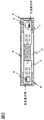
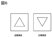
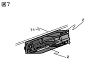
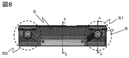
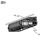
- FIG. 1 shows an overview of an embodiment of a stereo camera device according to the invention; It is a figure explaining the left-and-right imaging screen when the imaging board is mounted point-symmetrically. It is a figure which shows the stereo camera apparatus seen from the D direction of FIG. It is a figure which shows the stereo camera apparatus seen from E direction of FIG.
- FIG. 9 is a cross-sectional view of the stereo camera device taken along line AA of FIG. 8;
- FIG. 5 is a diagram showing an overview of the stereo camera apparatus of the present invention.
- the internal structure is shown in FIG.
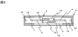
- FIG. 3 is a diagram including two imaging substrates 1 (first imaging substrate and second imaging substrate) and two main substrates 2 (first main substrate and second main substrate).
- FIG. 2 shows a view from the A direction in FIG. 1
- FIG. 3 shows a view from the B direction
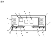
- FIG. 4 shows a view from the C direction
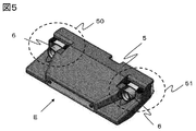
- a view from the E direction of FIG. 5 is shown in FIG.
- a cross-sectional view taken along line AA in FIG. 8 is shown in FIG.
- FIG. 7 is also a cross-sectional view taken along the line BB in FIG.
- a first imaging unit 50 left imaging unit
- a second imaging unit 51 right imaging unit
- the parallax is determined based on an image captured by the first imaging unit 50 and the second imaging unit 51, which is configured by the case 5 which is a housing in which the second imaging unit 51 is disposed at the other end.
- An object in front of the vehicle is recognized based on the distance image.
- recognition accuracy can be improved by arranging so that the optical axis of the first imaging unit 50 and the optical axis of the second imaging unit 51 are parallel.
- two imaging elements 3 first imaging element (left imaging element) and second imaging element (right imaging element)
- two communication substrates 4 a first communication connection unit, a second communication connection unit for outputting a captured image captured by the imaging device 3 to the outside of the apparatus (first imaging)
- a substrate (left imaging substrate) and a second imaging substrate (right imaging substrate)) are provided.
- the two imaging substrates 1 are disposed symmetrically with respect to the center of the case which is a housing, and in each of the imaging substrates 1, the communication connection portion 4 is disposed in parallel on the left or right of the imaging device 3, that is, Two main substrates 2 (first main substrate (power supply substrate), second main substrate (signal processing substrate)) disposed in parallel in the longitudinal direction of the case 5 which is the body, and between two imaging substrates 1
- a main connector 12 (first connection portion) and a main connector 13 (second connection portion) which are connection portions to be connected to each other are disposed, and the two main boards 2 are overlapped in the thickness direction of the threshold camera device. It is arranged.
- the thickness of the stereo camera device can be reduced, and the slime camera device can be thinned.
- this thickness is set to the margin of the imaging device 3 and the imaging substrate 1 and the case 5 in this embodiment, it is ideally possible to reduce the thickness to the thickness of the imaging device 3.
- FIG. 4 is a view of FIG. 1 as viewed in the C direction.
- the lens 6 is disposed in front of the imaging device 3 (in the imaging direction), and two main substrates 2 are disposed so as to overlap each other.
- the power supply unit 7, the video processing unit 8, and the recognition processing unit 9 are arranged on one main substrate in the main substrate 2, but the power supply unit 7 and the second By arranging the video processing unit 8 and the recognition processing unit 9 on the main substrate and separating the substrate between the power supply system and the signal processing system, it is possible to further reduce the noise.
- the surface of the first main substrate on which the power supply unit 7 is disposed and the surface of the second main substrate on which the video processing unit 8 and the recognition processing unit 9 are disposed are disposed to face each other.
- the flow of signals will be described with reference to FIG.
- Information of the outside world is taken into the image pickup device 3 as a captured image through the lens 6, and the taken image signal is transmitted to the main substrate 2 through the communication connection unit 4.
- the main substrate 2 comprises a power supply unit 7, an image processing unit 8, and a recognition processing unit 9.
- the image processing unit 8 optically corrects the image signal from the imaging substrate 1 and then performs stereo matching processing To obtain three-dimensional information (hereinafter referred to as parallax image).
- the recognition processing unit 9 narrows down necessary information using the corrected image and parallax image to recognize the recognition target.
- the two imaging elements 3 are disposed outside the imaging substrate 1 with respect to the center of gravity position of the stereo camera device or the center of the case 5 which is a housing, and the communication connection unit 4 is disposed inside the imaging substrate 1
- the distance between the two image pickup devices 3, ie, the length of The parallax value calculated by the device can be increased, and the effect of ensuring performance while achieving thinning can be achieved.
- the two imaging substrates 1 can also be disposed point-symmetrically as the same.
- the captured image captured is inverted on the left and right as shown in FIG. If this is left as it is, the image processing unit 8 can not obtain corresponding points of the left and right images when performing stereo matching. Therefore, the image signal can ensure its performance by rotating either left or right by 180 °.
- the process of rotating can be performed by any of the imaging device 3, the video processing unit 8, and the recognition processing unit 9.
- the imaging device 3 is rolling shutter control, as shown in FIG. 2, the scanning directions of the left and right imaging devices 3 and the readout start pixels are different.
- the first imaging device left imaging device
- the scanning direction of the second imaging element right imaging element
- performance can be secured by setting the scanning directions of the left and right imaging elements 3 and the readout start pixels to be substantially the same position.
- thinning can be realized by arranging the power supply substrate and the signal processing substrate as the main substrate 2 in parallel in the thickness direction of the case 5 between the two imaging substrates 1. It is possible.
- the communication connection part 4 in any one of the above-mentioned description becomes a connector, and handling at the time of manufacture of the imaging substrate 1 becomes easy by using the imaging substrate 1 and the main substrate 2 as soft substrates, such as FPC.
- the thermal expansion of the imaging substrates 1 on the left and right is imaged from low temperature to high temperature which is a vehicle environment. Since the process is performed centering on the element 3, the relative positional relationship between the left and right image pickup elements 3 is stabilized, which is an excellent configuration.
- FIG. 3 describes the screw A15 as the first fixing means, the fixing means is not selected. Further, in FIG. 3, the fixed locations are on both horizontal sides of the imaging device 3, but may be on both vertical sides. However, by using the same fixing means on the left and right sides, and fixing places on the left and right imaging substrates 1 as targets, it is possible to further suppress a decrease in the accuracy of parallax images.
- the communication connection portion 4 is disposed on the opposite side to the side where the imaging device 3 is disposed with respect to the imaging substrate 1, and is fixed to the fixture 11 to further stabilize the imaging substrate 1.
- the above-mentioned retention can be realized, and since the center of the imaging substrate 1 is distant from the center of the imaging element 3 because it is far from the center of the imaging element 3, the configuration is excellent in securing performance.
- the imaging substrate 1 is fixed to the fixing tool 11 with the screw B16 which is the second fixing means, the inner part of the imaging substrate 1 is not selected.
- the fixing force of the screw B16 (second fixing means) which is the fixing means the screw B16 is fixed by a smaller force than the fixing force of the screws A15 (first fixing means) on both sides of the imaging device 3 Further, the center of the imaging substrate 1 due to thermal expansion is less likely to be displaced from the center of the imaging device 3, and the configuration is excellent in securing performance.
- the fixture 11 in FIG. 4 may be a metal plate.
- the imaging substrate 1 has a long and thin shape
- the vibration resistance is improved by fixing the imaging substrate 1 to the metal plate, so that it can be said to be an excellent configuration because reliability can be ensured while realizing thinning. .
- the main substrate 2 is configured by two or more sheets, and has a connector which is at least one or more connection portions from each substrate.
- One main board 2 has a main connector 12 which is a first connection part of a power supply relationship
- the other main board 2 has a main connector 13 which is a second connection part of a video relation.
- the power supply relationship is large in noise
- the video relationship is susceptible to noise because a large number of signals from the image pickup device 3 are communicated at high speed, so performance can be secured if they are separately implemented.
- the configuration is excellent.
- thinning can be realized by making both of the two main substrates 2 approximately parallel to the vehicle window 14.
Landscapes
- Engineering & Computer Science (AREA)
- Multimedia (AREA)
- Signal Processing (AREA)
- Physics & Mathematics (AREA)
- General Physics & Mathematics (AREA)
- Studio Devices (AREA)
- Measurement Of Optical Distance (AREA)
- Testing, Inspecting, Measuring Of Stereoscopic Televisions And Televisions (AREA)
- Stereoscopic And Panoramic Photography (AREA)
- Cameras In General (AREA)
Abstract
Description
2 メイン基板
3 撮像素子
4 通信接続部
5 ケース
6 レンズ
7 電源部
8 映像処理部
9 認識処理部
11 固定具
12 メインコネクタ
13 メインコネクタ
14 車両窓
15 ねじA
16 ねじB
Claims (15)
- 第1の撮像素子と、
前記第1の撮像素子で撮像された第1の画像を出力する第1の通信接続部と、
前記第1の撮像素子と前記第1の通信接続部とが配置された第1の撮像基板と、
第2の撮像素子と、
前記第2の撮像素子で撮像された第2の画像を出力する第2の通信接続部と、
前記第2の撮像素子と前記第2の通信接続部とが配置された第2の撮像基板と、
一方端部に前記第1の撮像基板が配置され、他方端部に前記第2の撮像基板が配置された筐体と、を有し、
前記第1の撮像基板において、前記第1の撮像素子と前記第1の通信接続部とが前記筐体の長手方向に並列に配置され、
前記第2の撮像基板において、前記第2の撮像素子と前記第2の通信接続部とが前記筐体の長手方向に並列に配置され、
前記第1の撮像基板と前記第2の撮像基板は、左右対称に配置されたスレテオカメラ装置。 - 請求項1記載のスレテオカメラ装置において、
前記第1の撮像素子及び前記第2の撮像素子は、前記筐体の中心に対して外側に配置され、前記第1の通信接続部及び前記第2の通信接続部は、前記筐体の中心に対して内側に配置されたステレオカメラ装置。 - 請求項1記載のスレテオカメラ装置において、
前記第1の画像又は前記第2の画像を画像処理する処理部が配置された処理基板と、
前記処理基板と接続する第1の接続部と、を有し、
前記接続部は、前記第1の撮像基板と前記第2の撮像基板間に配置されたステレオカメラ装置。 - 請求項3記載のスレテオカメラ装置において、
電源を供給する電源部が配置された電源基板と、
前記電源基板と接続する第2の接続部と、を有し、
前記第2の接続部は、前記第1の撮像基板と前記第2の撮像基板間に配置されたステレオカメラ装置。 - 請求項3記載のスレテオカメラ装置において、
前記処理基板の前記処理部の配置面と、前記電源基板の前記電源部の配置面は、向き合うように配置されたステレオカメラ装置。 - 第1の撮像素子と、
前記第1の撮像素子で撮像された第1の画像を出力する第1の通信接続部と、
前記第1の撮像素子と前記第1の通信接続部とが配置された第1の撮像基板と、
第2の撮像素子と、
前記第2の撮像素子で撮像された第2の画像を出力する第2の通信接続部と、
前記第2の撮像素子と前記第2の通信接続部とが配置された第2の撮像基板と、
一方端部に前記第1の撮像基板が配置され、他方端部に前記第2の撮像基板が配置された筐体と、を有し、
前記第1の撮像基板において、前記第1の撮像素子と前記第1の通信接続部とが前記筐体の長手方向に並列に配置され、
前記第2の撮像基板において、前記第2の撮像素子と前記第2の通信接続部とが前記筐体の長手方向に並列に配置され、
前記第1の撮像基板と前記第2の撮像基板は、点対称に配置されたスレテオカメラ装置。 - 請求項6記載のスレテオカメラ装置において、
前記第1の撮像基板と前記第2の撮像基板は、同一の基板であるスレテオカメラ装置。 - 請求項7記載のスレテオカメラ装置において、
前記第1の撮像素子及び前記第2の通信接続部は、前記筐体の中心に対して外側に配置され、
前記第2の撮像素子及び前記第1の通信接続部は、前記筐体の中心に対して内側に配置されたステレオカメラ装置。 - 請求項6記載のスレテオカメラ装置において、
前記第1の撮像素子から取得した画像信号と、前記第2の撮像素子から取得した画像信号とは、一方を180°回転させて用いるステレオカメラ装置。 - 請求項6記載のスレテオカメラ装置において、
前記第1の撮像素子及び前記第2の撮像素子は、ローリングシャッター制御の場合、前記第1の撮像素子及び前記第2の撮像素子の走査方向及び読み出し開始画素を同じ位置とするステレオカメラ装置。 - 請求項1記載のスレテオカメラ装置において、
前記第1の撮像基板及び前記第2の撮像基板を、前記第1の撮像素子及び前記第2の撮像素子の両側から固定具に固定するスレテオカメラ装置。 - 請求項11記載のスレテオカメラ装置において、
前記固定具に固定する第1の固定手段は、前記第1の撮像素子及び前記第2の撮像素子を中心に対象の位置で固定するスレテオカメラ装置。 - 請求項11記載のスレテオカメラ装置において、
前記第1の撮像基板と及び前記第2の撮像基板の前記筐体の中心に対して内側部分に第2の固定手段にて前記固定具に固定するスレテオカメラ装置。 - 請求項13記載のスレテオカメラ装置において、
前記第1の固定手段の固定力よりも前記第2の固定手段の固定力の方が小さいステレオカメラ装置。 - 請求項11記載のスレテオカメラ装置において、
前記固定具は、金属プレートであるステレオカメラ装置。
Priority Applications (2)
| Application Number | Priority Date | Filing Date | Title |
|---|---|---|---|
| DE112013003554.5T DE112013003554B4 (de) | 2012-09-27 | 2013-07-26 | Stereokameravorrichtung |
| US14/420,382 US9912935B2 (en) | 2012-09-27 | 2013-07-26 | Stereo camera device |
Applications Claiming Priority (2)
| Application Number | Priority Date | Filing Date | Title |
|---|---|---|---|
| JP2012-213387 | 2012-09-27 | ||
| JP2012213387A JP5961506B2 (ja) | 2012-09-27 | 2012-09-27 | ステレオカメラ装置 |
Publications (1)
| Publication Number | Publication Date |
|---|---|
| WO2014050282A1 true WO2014050282A1 (ja) | 2014-04-03 |
Family
ID=50387696
Family Applications (1)
| Application Number | Title | Priority Date | Filing Date |
|---|---|---|---|
| PCT/JP2013/070270 Ceased WO2014050282A1 (ja) | 2012-09-27 | 2013-07-26 | ステレオカメラ装置 |
Country Status (4)
| Country | Link |
|---|---|
| US (1) | US9912935B2 (ja) |
| JP (1) | JP5961506B2 (ja) |
| DE (1) | DE112013003554B4 (ja) |
| WO (1) | WO2014050282A1 (ja) |
Cited By (3)
| Publication number | Priority date | Publication date | Assignee | Title |
|---|---|---|---|---|
| JP2016014564A (ja) * | 2014-07-01 | 2016-01-28 | 株式会社リコー | 撮像ユニット |
| CN107409172A (zh) * | 2015-04-24 | 2017-11-28 | 日立汽车系统株式会社 | 摄像装置 |
| JP2020038230A (ja) * | 2014-07-01 | 2020-03-12 | 株式会社リコー | 撮像ユニット |
Families Citing this family (8)
| Publication number | Priority date | Publication date | Assignee | Title |
|---|---|---|---|---|
| JP6220754B2 (ja) * | 2014-08-26 | 2017-10-25 | 日立オートモティブシステムズ株式会社 | 車載用カメラ |
| JP6268085B2 (ja) * | 2014-12-24 | 2018-01-24 | 株式会社東海理化電機製作所 | 撮像装置 |
| KR102502451B1 (ko) | 2016-01-07 | 2023-02-22 | 삼성전자주식회사 | 깊이 추정 방법 및 장치, 및 거리 추정기 학습 방법 및 장치 |
| JP7020844B2 (ja) * | 2017-09-29 | 2022-02-16 | 株式会社デンソー | 車載カメラ装置 |
| DE102018218992B4 (de) * | 2017-11-10 | 2023-02-16 | Denso Corporation | Kameramodul |
| NO20201379A1 (en) | 2018-06-12 | 2020-12-16 | Baker Hughes Holdings Llc | Gas ratio volumetrics for reservoir navigation |
| JP7154120B2 (ja) * | 2018-12-11 | 2022-10-17 | 日立Astemo株式会社 | ステレオカメラ装置 |
| JP2025167780A (ja) * | 2024-04-26 | 2025-11-07 | ミツミ電機株式会社 | 駆動装置、カメラモジュールおよびカメラ搭載装置 |
Citations (5)
| Publication number | Priority date | Publication date | Assignee | Title |
|---|---|---|---|---|
| JP2006033346A (ja) * | 2004-07-15 | 2006-02-02 | Mitsubishi Electric Corp | 着脱型撮像装置 |
| JP2006101154A (ja) * | 2004-09-29 | 2006-04-13 | Canon Inc | 撮像装置 |
| WO2011068139A1 (ja) * | 2009-12-01 | 2011-06-09 | Inaba Minoru | 立体映像撮像装置 |
| JP2011123078A (ja) * | 2004-11-15 | 2011-06-23 | Hitachi Automotive Systems Ltd | ステレオカメラ |
| JP2012173737A (ja) * | 2011-02-17 | 2012-09-10 | Samsung Electro-Mechanics Co Ltd | ステレオカメラ及びその製造方法 |
Family Cites Families (11)
| Publication number | Priority date | Publication date | Assignee | Title |
|---|---|---|---|---|
| JP3353408B2 (ja) | 1993-08-02 | 2002-12-03 | 三菱電機株式会社 | 車載用撮影装置 |
| JP3631270B2 (ja) | 1994-10-13 | 2005-03-23 | オリンパス株式会社 | 電子機器 |
| JP4031104B2 (ja) | 1998-02-20 | 2008-01-09 | 富士重工業株式会社 | ステレオカメラ |
| JP3919321B2 (ja) * | 1998-03-10 | 2007-05-23 | キヤノン株式会社 | 撮像装置 |
| JP3894364B2 (ja) | 2002-02-04 | 2007-03-22 | 富士フイルム株式会社 | カメラ |
| JP4241013B2 (ja) * | 2002-11-26 | 2009-03-18 | 富士ゼロックス株式会社 | 画像形成装置並びにこれに用いられるフレーム構造及びその製造方法 |
| JP3684365B2 (ja) * | 2003-02-21 | 2005-08-17 | フジノン株式会社 | 立体電子内視鏡用撮像装置 |
| US8081207B2 (en) * | 2006-06-06 | 2011-12-20 | Point Grey Research Inc. | High accuracy stereo camera |
| JP2008306350A (ja) | 2007-06-06 | 2008-12-18 | Hitachi Maxell Ltd | カメラモジュール及び撮像装置 |
| KR101149021B1 (ko) | 2010-10-08 | 2012-05-24 | 엘지이노텍 주식회사 | 3차원 촬상장치와 그 제조방법 |
| US9204041B1 (en) * | 2012-07-03 | 2015-12-01 | Gopro, Inc. | Rolling shutter synchronization |
-
2012
- 2012-09-27 JP JP2012213387A patent/JP5961506B2/ja not_active Expired - Fee Related
-
2013
- 2013-07-26 DE DE112013003554.5T patent/DE112013003554B4/de not_active Expired - Fee Related
- 2013-07-26 WO PCT/JP2013/070270 patent/WO2014050282A1/ja not_active Ceased
- 2013-07-26 US US14/420,382 patent/US9912935B2/en not_active Expired - Fee Related
Patent Citations (5)
| Publication number | Priority date | Publication date | Assignee | Title |
|---|---|---|---|---|
| JP2006033346A (ja) * | 2004-07-15 | 2006-02-02 | Mitsubishi Electric Corp | 着脱型撮像装置 |
| JP2006101154A (ja) * | 2004-09-29 | 2006-04-13 | Canon Inc | 撮像装置 |
| JP2011123078A (ja) * | 2004-11-15 | 2011-06-23 | Hitachi Automotive Systems Ltd | ステレオカメラ |
| WO2011068139A1 (ja) * | 2009-12-01 | 2011-06-09 | Inaba Minoru | 立体映像撮像装置 |
| JP2012173737A (ja) * | 2011-02-17 | 2012-09-10 | Samsung Electro-Mechanics Co Ltd | ステレオカメラ及びその製造方法 |
Cited By (5)
| Publication number | Priority date | Publication date | Assignee | Title |
|---|---|---|---|---|
| JP2016014564A (ja) * | 2014-07-01 | 2016-01-28 | 株式会社リコー | 撮像ユニット |
| JP2020038230A (ja) * | 2014-07-01 | 2020-03-12 | 株式会社リコー | 撮像ユニット |
| CN107409172A (zh) * | 2015-04-24 | 2017-11-28 | 日立汽车系统株式会社 | 摄像装置 |
| US20180054552A1 (en) * | 2015-04-24 | 2018-02-22 | Hitachi Automotive Systems, Ltd. | Imaging Device |
| CN107409172B (zh) * | 2015-04-24 | 2020-05-19 | 日立汽车系统株式会社 | 摄像装置 |
Also Published As
| Publication number | Publication date |
|---|---|
| US9912935B2 (en) | 2018-03-06 |
| JP5961506B2 (ja) | 2016-08-02 |
| DE112013003554B4 (de) | 2023-01-12 |
| US20150215606A1 (en) | 2015-07-30 |
| JP2014066948A (ja) | 2014-04-17 |
| DE112013003554T5 (de) | 2015-04-09 |
Similar Documents
| Publication | Publication Date | Title |
|---|---|---|
| JP5961506B2 (ja) | ステレオカメラ装置 | |
| JP7266165B2 (ja) | 撮像装置、撮像システム、および表示システム | |
| JP4848795B2 (ja) | ステレオカメラ | |
| JP5793122B2 (ja) | 車載画像処理装置 | |
| JP6573713B2 (ja) | 車載画像処理装置 | |
| EP2881774B1 (en) | Lens attachment mechanism, lens attachment method and imaging device | |
| US10992920B2 (en) | Stereo image processing device | |
| EP3046077A1 (en) | Three-dimensional camera assembly, terminal apparatus and ranging method | |
| JP2016014564A (ja) | 撮像ユニット | |
| JP2009068906A (ja) | 距離測定装置 | |
| US10220783B2 (en) | Vehicle-mounted stereo camera device and method for correcting the same | |
| US12069226B2 (en) | Imaging device | |
| JP2012189324A (ja) | ステレオカメラ | |
| JP2014065393A (ja) | ステレオカメラ装置 | |
| EP3288250B1 (en) | Imaging device | |
| CN104065856A (zh) | 立体相机单元 | |
| JP6158258B2 (ja) | 車載画像処理装置 | |
| JP6430586B2 (ja) | 車用ステレオビジョンシステム | |
| WO2012169363A1 (ja) | ステレオカメラの製造方法及びステレオカメラ | |
| KR20160126649A (ko) | 차량 장착용 카메라 | |
| JP2016031308A (ja) | 撮像装置、撮像システム、及び、移動体 |
Legal Events
| Date | Code | Title | Description |
|---|---|---|---|
| 121 | Ep: the epo has been informed by wipo that ep was designated in this application |
Ref document number: 13841878 Country of ref document: EP Kind code of ref document: A1 |
|
| WWE | Wipo information: entry into national phase |
Ref document number: 14420382 Country of ref document: US |
|
| WWE | Wipo information: entry into national phase |
Ref document number: 112013003554 Country of ref document: DE Ref document number: 1120130035545 Country of ref document: DE |
|
| 122 | Ep: pct application non-entry in european phase |
Ref document number: 13841878 Country of ref document: EP Kind code of ref document: A1 |