WO2014046015A1 - 商品収納装置 - Google Patents
商品収納装置 Download PDFInfo
- Publication number
- WO2014046015A1 WO2014046015A1 PCT/JP2013/074745 JP2013074745W WO2014046015A1 WO 2014046015 A1 WO2014046015 A1 WO 2014046015A1 JP 2013074745 W JP2013074745 W JP 2013074745W WO 2014046015 A1 WO2014046015 A1 WO 2014046015A1
- Authority
- WO
- WIPO (PCT)
- Prior art keywords
- product
- product storage
- downstream
- gate member
- main gate
- Prior art date
- Legal status (The legal status is an assumption and is not a legal conclusion. Google has not performed a legal analysis and makes no representation as to the accuracy of the status listed.)
- Ceased
Links
Images

















Classifications
-
- G—PHYSICS
- G07—CHECKING-DEVICES
- G07F—COIN-FREED OR LIKE APPARATUS
- G07F11/00—Coin-freed apparatus for dispensing, or the like, discrete articles
- G07F11/02—Coin-freed apparatus for dispensing, or the like, discrete articles from non-movable magazines
- G07F11/38—Coin-freed apparatus for dispensing, or the like, discrete articles from non-movable magazines in which the magazines are horizontal
- G07F11/42—Coin-freed apparatus for dispensing, or the like, discrete articles from non-movable magazines in which the magazines are horizontal the articles being delivered by motor-driven means
-
- G—PHYSICS
- G07—CHECKING-DEVICES
- G07F—COIN-FREED OR LIKE APPARATUS
- G07F11/00—Coin-freed apparatus for dispensing, or the like, discrete articles
- G07F11/64—Coin-freed apparatus for dispensing, or the like, discrete articles in which the articles are individually suspended from stationary supports
-
- G—PHYSICS
- G07—CHECKING-DEVICES
- G07F—COIN-FREED OR LIKE APPARATUS
- G07F11/00—Coin-freed apparatus for dispensing, or the like, discrete articles
- G07F11/02—Coin-freed apparatus for dispensing, or the like, discrete articles from non-movable magazines
- G07F11/38—Coin-freed apparatus for dispensing, or the like, discrete articles from non-movable magazines in which the magazines are horizontal
- G07F11/40—Coin-freed apparatus for dispensing, or the like, discrete articles from non-movable magazines in which the magazines are horizontal the articles being delivered by hand-operated means
-
- G—PHYSICS
- G07—CHECKING-DEVICES
- G07F—COIN-FREED OR LIKE APPARATUS
- G07F11/00—Coin-freed apparatus for dispensing, or the like, discrete articles
- G07F11/46—Coin-freed apparatus for dispensing, or the like, discrete articles from movable storage containers or supports
- G07F11/60—Coin-freed apparatus for dispensing, or the like, discrete articles from movable storage containers or supports the storage containers or supports being rectilinearly movable
Definitions
- the present invention relates to a product storage device applied to a vending machine that sells products such as plastic bottled drinks.
- vending machines that sell products such as beverages in plastic bottles which have a product storage device including a product storage column for storing products and a bucket for transporting products.
- the product storage column stores a plurality of products in an aligned state.
- the carry-out device is driven, the product storage column pays out products one by one from its front end.
- a plurality of product storage columns are juxtaposed in the left-right direction on a product rack.
- the bucket is for accepting the product carried out from the product storage column.
- the bucket is provided so as to be movable up and down and left and right in the front area of the product rack by bucket driving means.
- the bucket driving means includes an X-axis transport mechanism that can move the bucket along the left-right direction, and a Y-axis transport mechanism that moves the bucket including the X-axis transport mechanism along the vertical direction. Has been.
- the product storage apparatus not only has an excessive number of parts, but also requires an expensive sensor and the like, resulting in an increase in cost.
- an object of the present invention is to provide a product storage device capable of preventing a plurality of products from being taken out from a product rack by a single take-out operation while reducing costs.
- a product storage device is a product storage device provided with a product rack in which a plurality of product storage columns for storing products in a line in a product storage passage are arranged in parallel.
- the product storage column is pivotally provided so as to move forward and backward with respect to the product storage passage, and is normally held in a state of being advanced into the product storage passage and positioned downstream of the most downstream product.
- a main gate member that allows the most downstream product to be taken out and taken out
- a guide member extending along the juxtaposed direction of the commodity storage columns, and a plurality of pieces housed in the guide member housing area so as to be slidable along the extending direction of the guide member
- the adjustment member is caused to enter the accommodation area so that the total width of the space in the accommodation area is made smaller than the width of the accessible portion of the main gate member.
- the restricting unit disengages the guide member from the rotation locus of the enterable portion of the main gate member when replenishment of the commodity in the commodity rack is allowed.
- the main gate member is allowed to be retracted from the commodity storage passage by being moved to the position.
- the present invention provides the product storage device, wherein the product storage device is rotatably provided in association with the main gate member in a manner of moving forward and backward with respect to the product storage passage, and the main gate member has advanced into the product storage passage.
- the main gate member When the main gate member is retracted from the product storage passage, the main gate member advances into the product storage passage and is adjacent to the upstream side of the most downstream product.
- a sub-gate member that regulates movement of the second product to the downstream side, and the sub-gate member is taken out in a posture in which an upper portion is inclined to the upstream side when the sub-gate member advances into the product storage passage.
- a pressing portion that presses the most downstream product toward the downstream side.
- the present invention is characterized in that, in the product storage device, the pressing portion of the sub-gate member abuts on the most downstream product when the sub-gate member is retracted from the product storage passage.
- the present invention provides the product storage device, wherein the product storage column extends along the product storage passage, and a constricted portion is provided between the lid mounting portion to which the lid body is detachably attached and the body portion.
- the present invention provides the product storage device, wherein the downstream end portion includes a restricting portion that is narrower than the constricted portion, and the restricting portion normally has the most downstream product directed toward the downstream side. While restricting passage, when the most downstream product is taken out, it is elastically deformed so as to be wider than the constricted portion by being pressed by the most downstream product, and the most downstream product passes. It is characterized by accepting.
- the present invention provides the product storage device, wherein the rail member includes a metal rail base that supports the product in a state of being suspended substantially horizontally from the upstream side to the downstream side, and the lower end side end portion. And a pair of left and right resin lower rails attached to the lower end of the rail base, each of the lower rails being elastically displaceable along the vertical direction with respect to the rail base. It is characterized by being arranged.
- the present invention is provided in the above-described product storage device so as to be rotatable in such a manner as to move forward and backward with respect to the product storage passage, and is normally urged by an urging means to advance into the product storage passage.
- the main gate member retreats from the product storage passage, the second product is restricted from moving downstream, and the contact portion of the main product is brought into contact with the main gate member.
- a shutter member is provided that retracts from the commodity storage passage against the urging force of the urging means and allows the second commodity to move downstream.
- the main gate member that is pivotably provided so as to move forward and backward with respect to the product storage passage for each product storage column normally advances into the product storage passage to the downstream side of the most downstream product.
- the most downstream product is allowed to be taken out.
- a guide member extending along the direction in which the product storage columns are arranged, and a plurality of piece members housed in the guide member housing area so as to be slidable along the extending direction of the guide member.
- the regulating means is configured to allow the adjustment member to enter the accommodation area, thereby reducing the total width of the space in the accommodation area to be smaller than the width of the accessible portion of the main gate member.
- the total width of the space in the storage area is set to the width of the accessible portion by removing the adjustment member from the storage area.
- any one main gate member is allowed to retract from the product storage passage, and the other main gate member is retracted from the product storage passage. It regulates. This suppresses the user from taking out a plurality of products in one take-off operation when the sale of the product rack is permitted without using the bucket drive means as in the conventional product storage device. Can do. Therefore, it is possible to prevent a plurality of products from being taken out from the product rack by a single take-out operation while reducing the cost.
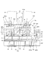
- FIG. 1 is a front view showing a vending machine to which a product storage device according to an embodiment of the present invention is applied.
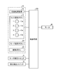
- FIG. 2 is a block diagram showing a control system of a vending machine to which the product storage device according to the embodiment of the present invention is applied.
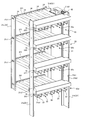
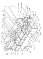
- FIG. 3 is a perspective view showing the product storage device of the vending machine shown in FIG. 1, with some components removed.
- FIG. 4 is an explanatory view showing a rack support side plate provided inside the storage chamber of the main body cabinet.
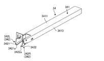
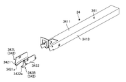
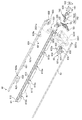
- FIG. 5 is a perspective view showing a rail member constituting the product storage column shown in FIGS. 1 and 3. 6 is an exploded perspective view of the rail member shown in FIG.
- FIG. 7 is a cross-sectional plan view showing the structure of the front end rail portion shown in FIGS.
- FIG. 8 is a cross-sectional plan view showing the configuration of the front end rail portion shown in FIGS. 5 and 6 as viewed from above.
- FIG. 9 is a plan view showing a main part of the product rack shown in FIG. 1 or 3.
- FIG. 10 is a perspective view showing the main part of the product rack shown in FIG.
- FIG. 11 is a perspective view showing the main part of the product rack shown in FIG.
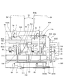
- FIG. 12 schematically shows a product storage column constituting the product rack, and is a longitudinal sectional view showing the product rack as viewed from the right side.
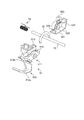
- FIG. 13 is a perspective view showing the take-out mechanism.
- FIG. 14 is an exploded perspective view of the main element of the take-out mechanism.
- FIG. 15 is a side view of the take-out mechanism as seen from the right side.
- FIG. 16 is a side view of the take-out mechanism as viewed from the left side.
- FIG. 17 is an exploded perspective view of some components of the product rack shown in FIGS.
- FIG. 18 is an explanatory view schematically showing a main part of a regulating mechanism constituting the product storage device according to the embodiment of the present invention.
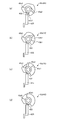
- FIG. 19 is a perspective view showing a switching cam member constituting the rack selection mechanism, in which (a) is a switching cam member corresponding to the uppermost product rack, and (b) is a second product rack from the uppermost product rack.
- FIG. 20 is an explanatory diagram showing the relationship between the switching cam member, the slide plate, and the link slide member at the “standby position”.
- FIG. 21 is an explanatory diagram illustrating the relationship between the switching cam member, the slide plate, and the link slide member at the “60 ° rotation position”.
- FIG. 22 is an explanatory diagram showing the relationship between the switching cam member, the slide plate, and the link slide member at the “120 ° rotation position”.
- FIG. 23 is an explanatory diagram showing the relationship between the switching cam member, the slide plate, and the link slide member at the “180 ° rotation position”.
- FIG. 24 is an explanatory diagram showing the relationship between the switching cam member, the slide plate, and the link slide member at the “240 ° rotation position”.
- FIG. 25 is an explanatory diagram showing the relationship between the switching cam member, the slide plate, and the link slide member at the “300 ° rotation position”.
- FIG. 26 is a flowchart showing the main processing contents of the sales control processing executed by the control means shown in FIG.
- FIG. 27 is a perspective view showing the main part of the product rack as viewed from the right front side.
- FIG. 28 is a longitudinal sectional view showing a product storage column constituting the product rack as viewed from the right side.
- FIG. 29 is a plan view showing the main part of the product rack.
- FIG. 30 is a flowchart showing the main processing contents of the replenishment control processing performed by the control means shown in FIG.
- FIG. 31 is a plan view showing the main part of the product rack.
- FIG. 32 is a longitudinal sectional view showing a product storage column constituting the product rack as viewed from the right side.
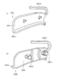
- FIGS. 33A and 33B show a modification of the front end rail portion according to the embodiment of the present invention.
- FIG. 33A is a perspective view of the left front end rail portion
- FIG. 33B is a perspective view of the right front end rail portion.
- FIG. 34 is a perspective view showing a main part of the product storage column to which the front end rail portion shown in FIG. 33 is attached.
- FIG. 34 is a perspective view showing a main part of the product storage column to which the front end rail portion shown in FIG. 33 is attached.
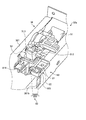
- FIG. 35 is a perspective view showing a main configuration of a modification of the product storage device according to the embodiment of the present invention.
- FIG. 36 is a perspective view showing a shutter member constituting the shutter mechanism shown in FIG.
- FIG. 37 is a perspective view showing a mounting base constituting the shutter mechanism shown in FIG.
- FIG. 38 is a perspective view showing a main configuration of a modified example of the product storage device according to the embodiment of the present invention.
- FIG. 39 is a front view showing a modification of the vending machine to which the product storage device according to the embodiment of the present invention is applied.
- FIG. 1 and 2 each show a vending machine to which a product storage apparatus according to an embodiment of the present invention is applied
- FIG. 1 is a front view
- FIG. 2 is a block diagram showing a control system. is there.
- the vending machine exemplified here sells a product such as a canned beverage or a beverage containing a plastic bottle in a cooled or heated state, and includes a main body cabinet 1.
- the main body cabinet 1 is a rectangular parallelepiped housing whose opening formed on the front surface is opened and closed by the outer door 2.
- the outer door 2 is configured by appropriately using a heat insulating material, and has a window portion 2a in which a transparent plate material such as heat insulating glass is fitted. Therefore, the vending machine can visually recognize the inside through the window 2a of the outer door 2.
- a handle (not shown) is provided at the central portion of the left side surface on the left end side of the outer door 2.
- the main body cabinet 1 is divided into an upper part and a lower part, and the upper side is a storage room 1a and the lower side is a machine room 1b.
- the storage chamber 1a is a chamber that holds the interior of the storage chamber 1a in a preset temperature state, and the wall members that form the storage chamber 1a are each formed of a heat insulating material.
- the storage chamber 1a has a means (not shown) for cooling the internal air of the storage chamber 1a, such as an evaporator, and an internal heater 1a for heating the internal air of the storage chamber 1a, such as an electric heater. Means (not shown) are provided.
- the machine room 1b is provided with a refrigerator (not shown) and various control devices (not shown) constituting a refrigeration cycle together with the evaporator.
- the input processing unit 10 is attached to the upper part of the left side surface of the main body cabinet 1.
- the input processing unit 10 includes a box-shaped unit body 11.
- the unit body 11 has a robust configuration. On the front surface of the unit main body 11, a coin slot 12, a rack selection button 13, and the like are provided.
- the left side of the unit body 11 can be opened and closed by a unit door (not shown), and the mode selection button 14 and the release button 15 are exposed when the unit door is opened.
- the unit door is normally restricted from opening by a lock mechanism (not shown), and can be opened by an administrator or the like operating the lock mechanism.
- a money processing device 16 is provided inside the unit main body 11.
- the coin insertion slot 12 is an opening for inserting coins.
- rack selection buttons 13 which are push buttons provided so as to be lined up and down.
- Each of the rack selection buttons 13 is associated with product racks 30a to 30d constituting a product storage device 20 described later, and gives an input signal to the control means 100 when pressed by the user.
- Each rack selection button 13 includes a light source 13a such as an LED. These light sources 13 a are turned on in response to a lighting command given from the control means 100.
- the mode selection button 14 gives a supplement signal to the control means 100 when pressed by the administrator.
- the release button 15 gives a release signal to the control means 100 when pressed by the administrator.
- the money processing device 16 discriminates the authenticity and denomination of coins inserted through the coin insertion slot 12, and performs money processing for storing coins for each denomination.
- the money processing device 16 provides the control means 100 with money amount information inserted through the coin insertion slot 12 and pays out change. The change is paid out through the coin return port 17.
- the money processing device 16 pays out coins inserted through the coin return port 17 even when the user operates the return button 18 after coins have been inserted through the coin input port 12. Further, the money processing device 16 pays out coins through the coin return port 17 even for coins that could not be identified.
- FIG. 3 is a perspective view showing the product storage device 20 of the vending machine shown in FIG. 1, with some components removed.
- the product storage device 20 includes product racks 30a to 30d and a rack selection mechanism 40.
- the product racks 30a to 30d are provided in plural (four in the illustrated example).
- the product racks 30a to 30d are provided in a plurality of stages along the vertical direction so as to be bridged between the pair of left and right rack support side plates 31.
- the rack support side plate 31 is formed by bending a steel plate, and as shown in FIG. 4, each rack support side plate 31 is provided in the storage chamber 1a so as to extend along the vertical direction.
- the left front rack support side plate 31a and the right front rack support side plate 31b form a pair of left and right
- the left rear rack support side plate 31c and the right rear rack support side plate 31d form a pair of left and right. is doing.
- the left rear rack support side plate 31c and the right rear rack support side plate 31d are provided with support pieces 31c1 and 31d1 (see FIG. 4) for supporting the product racks 30a to 30d in such a manner as to protrude from surfaces facing each other. is there.
- the left front rack support side plate 31a and the right front rack support side plate 31b have screw holes 31a2 and 31b2 through which screw members N as fastening members can be inserted into the front surfaces 31a1 and 31b1, that is, the surface facing the front opening of the main body cabinet 1. A plurality are formed.
- a rear horizontal member 321 that is a rear part is locked to the support pieces 31c1 and 31d1
- a front base member 322 that is a front part is a left front rack support side plate 31a and a right front rack support side plate 31b.
- a screw member N is inserted into and screwed into predetermined screw holes 31a2 and 31b2 on the front surfaces 31a1 and 31b1, and is fastened and attached to the screw member N.
- each of the product racks 30a to 30d stores a product of a beverage containing a plastic bottle, and has the same configuration.
- the product of a beverage containing a plastic bottle is an interior of a container (pet bottle) having a constricted portion 202 between a cap attaching portion 200 a to which the cap 200 is detachably attached and the body portion 201. Beverage is enclosed in
- Each of the product racks 30a to 30d is configured by arranging a plurality (five in the illustrated example) of product storage columns 33 along the left-right direction.
- Each of these product storage columns 33 includes a rail member 34.
- the rail member 34 extends along the front-rear direction and defines a product storage passage 33a.
- FIG. 5 is a perspective view showing a rail member 34 constituting the product storage column 33 shown in FIGS. 1 and 3, and FIG. 6 is an exploded perspective view of the rail member 34 shown in FIG.
- the rail member 34 includes a rail base body 341 and a front end rail portion 342.
- the rail base 341 is formed by appropriately bending a steel plate, and has a long shape whose longitudinal direction is the longitudinal direction.
- the rail base body 341 has a base 3411, a lower left extension 3412, and a lower right extension 3413 that are integrally formed so as to have a U shape that opens downward when viewed from the front.
- the base 3411 is a horizontal part extending along the front-rear direction.
- the base portion 3411 has a rear end portion supported by the rear horizontal member 321 and a front end portion supported by the front base member 322.
- the lower left extended portion 3412 extends downward from the left end portion of the base portion 3411, and the extended end portion bends rightward to form a left edge portion 3412a (see FIG. 12). It is L-shaped when viewed from the front.
- the lower right extended portion 3413 extends downward from the right end portion of the base portion 3411, and the extended end portion is bent leftward to form a right edge portion (not shown). When viewed from the front, it has an inverted L shape.
- the left lower extending portion 3412 and the right lower extending portion 3413 are a pair of left and right, and define a part of the product storage passage 33a by a gap between them, and the width (the left edge portion 3412a and the right edge portion). (Minimum width with respect to the portion) is larger than the maximum width of the constricted portion 202 of the target product (beverage in a plastic bottle) and smaller than the maximum width of the cap mounting portion 200a of the product.
- the front end rail portion 342 is formed of a resin material, and the left front end rail portion 342L and the right front end rail portion 342R are configured as a pair of left and right.
- the left front end rail portion 342L has a front end left base portion 3421 and a left front end edge end portion 3421a formed integrally, and has an L shape when viewed from the front.
- the front end left base portion 3421 is a flat plate portion extending along the up-down direction.
- the left front end edge portion 3421a is formed by bending the lower end portion of the front end left base portion 3421 toward the right.
- the right front end rail portion 342R has a front end right base portion 3422 and a right front end edge end portion 3422a integrally formed, and has an inverted L shape when viewed from the front.
- the front end right base 3422 is a flat plate-like portion extending along the up-down direction.
- the right front end edge end portion 3422a is formed by bending the lower end portion of the front end left base portion 3421 toward the left.
- the left front end rail portion 342L and the right front end rail portion 342R define a front end portion (downstream end portion) of the product storage passage 33a with a gap between each other, and gradually incline downward toward the front. is doing.
- the left front end rail portion 342L and the right front end rail portion 342R have a size that can enter the front end portion of the rail base body 341, and the predetermined portion is locked by entering the front end portion.
- the left front end edge portion 3421a of the left front end rail portion 342L is attached to the left edge portion 3412a, and the right front end edge portion 3422a of the right front end rail portion 342R is attached to the right edge portion. .
- the rail member 34 is curved in such a manner that the front end portion (downstream end portion) is gradually inclined downward.
- FIGS. 7 and 8 show the configuration of the front end rail portion 342 shown in FIGS. 5 and 6, respectively, and are cross-sectional plan views showing the case viewed from above.
- the left front end rail portion 342L and the right front end rail portion 342R are provided with raised portions 3421a1 and 3422a1 at locations corresponding to each other.
- the raised portion 3421a1 (hereinafter also referred to as the left raised portion 3421a1) of the left front end rail portion 342L is formed by protruding toward the product storage passage 33a in a substantially central region of the left front end edge portion 3421a.
- a left long hole 3421a2 and a left protrusion 3421a3 are provided in a substantially central region of the left front end edge 3421a.
- the left long hole portion 3421a2 is a long hole whose longitudinal direction is the longitudinal direction.
- the left protrusion 3421a3 is formed so as to protrude toward a portion where the left raised portion 3421a1 is formed in a portion facing the portion where the left raised portion 3421a1 is formed in the left elongated hole portion 3421a2.
- the raised portion 3422a1 (hereinafter also referred to as the right raised portion 3422a1) of the right front end rail portion 342R is raised toward the product storage passage 33a at a position facing the left raised portion 3421a1 in a substantially central region of the right front end edge portion 3422a. It is formed by doing.
- a right long hole 3422a2 and a right protrusion 3422a3 are provided in a substantially central region of the right front end edge 3422a.
- the right long hole portion 3422a2 is a long hole whose longitudinal direction is the longitudinal direction.
- the right protrusion 3422a3 is formed so as to protrude toward a portion where the right raised portion 3422a1 is formed in a portion facing the portion where the right raised portion 3422a1 is formed in the right long hole portion 3422a2.
- the width L1 between the left raised portion 3421a1 and the right raised portion 3422a1 is the width of the constricted portion 202 of the target product (plastic bottled beverage). It is formed smaller than the maximum width.
- the product is restricted from moving back and forth between the left and right raised portions 3421a1 and 3422a1, and the product is pressed forward or backward by a take-out operation or a replenishment operation described later.
- the left protruding portion 3421a1 of the left elongated hole portion 3421a2 is elastically deformed until it abuts the left protrusion 3421a3, and in the substantially central region of the right front edge portion 3422a.
- the width L1 between the left and right raised portions 3421a1 and 3422a1 becomes larger than the maximum width of the constricted portion 202 by elastically deforming the portion where the right raised portion 3422a1 of the right elongated hole portion 3422a2 is in contact with the right protrusion 3422a3. In this way, the product is allowed to move.
- the rail member 34 when the product is put up from the front so that the constricted portion 202 of the product is inserted into the product storage passage 33a, the left edge portion 3412 and the right edge portion of the rail base 341, A part of the cap mounting portion 200a of the product is placed on the right front end edge end portion 3422a and the left front end edge end portion 3421a of the front end rail portion 342.
- the rail member 34 supports the product cap mounting portion 200a to support the product in a suspended state, and stores the product in the product storage passage 33a so as to be lined up in the front-rear direction. is there. Then, by attaching the rail member 34 so as to be gradually inclined downward as it goes forward, the product stored in the product storage passage 33a is stored in a state where it can be moved forward by its own weight.
- the foremost product (the most downstream product) among the products stored in the product storage passage 33a is located on the rear side of the front end rail portion 342 between the left and right raised portions 3421a1 and 3422a1, and these left and right raised portions. Forward movement is restricted by 3421a1 and 3422a1.
- FIG. 9 is a plan view showing the main parts of the product racks 30a to 30d shown in FIGS. 1 and 3.
- FIG. 10 is a plan view of the main parts of the product racks 30a to 30d shown in FIG.
- FIG. 11 is a perspective view showing the main part of the product racks 30a to 30d shown in FIG. 9 as viewed obliquely from the right rear. In FIGS. 9 to 11, components are appropriately omitted for clarity of illustration.
- FIG. 12 schematically shows the product storage column 33 constituting the product racks 30a to 30d, and is a longitudinal sectional view showing the case when viewed from the right side.
- the commodity racks 30 a to 30 d include a take-out mechanism 50, a support mechanism 60, and a regulation mechanism (regulation means) 70.
- the take-out mechanism 50 is provided for each product storage column 33 and includes a main gate member 51 and a sub-gate member 52.
- FIG. 13 is a perspective view showing the take-out mechanism 50
- FIG. 14 is an exploded perspective view of main elements of the take-out mechanism 50
- FIG. 15 is a side view of the take-out mechanism 50 viewed from the right side. These are the side views which looked at the extraction mechanism 50 from the left side.
- the take-out mechanism 50 will be described using these FIGS. 13 to 16 as appropriate.
- the main gate member 51 extends in the left-right direction, and is supported by a gate shaft portion 53 that is installed on a right support member 323 and a left support member (not shown), which will be described later, in an upper region of the foremost product.
- tip part 512 which comprises the form which extends toward the front side rather than this 1st base end part 511 and protrudes toward the downward direction from the middle are provided.
- a sliding portion 512a constituting a curved surface is provided below the first tip portion 512.
- the main gate member 51 can rotate around the central axis of the gate shaft 53 around the central axis.
- a gate spring member 54 is interposed between the main gate member 51 and the gate shaft portion 53. Therefore, the main gate member 51 is biased by the gate spring member 54 and turned downward, and the first tip portion 512 has advanced into the product storage passage 33a.
- the main gate member 51 includes a first engagement piece 513 that protrudes rearward.
- the sub-gate member 52 is provided on the rear side of the main gate member 51, and enters the first base end portion 511 to be supported by the gate shaft portion 53, and the second base end portion 521.
- a second distal end portion 522 that extends rearward from the base end portion 521 and has a lower end projecting downward from the second base end portion 521 is provided.
- the sub-gate member 52 can rotate around the central axis of the gate shaft portion 53. That is, the sub-gate member 52 is disposed so as to be rotatable around the central axis of the common shaft portion with the main gate member 51.
- Such a sub-gate member 52 is connected to the main gate member 51 via a coil spring member 55. More specifically, when the coil spring member 55 is hooked between the hook groove 516 of the main gate member 51 and the hook groove 526 of the sub gate member 52, the coil spring member 55 is biased to the main gate member 51 and the sub gate. The mutual positional relationship with the member 52 is defined.
- the sub-gate member 52 assumes a posture in which its second tip portion 522 is retracted from the product storage passage 33a. Is.
- the first front end portion 512 of the main gate member 51 is retracted from the product storage passage 33a
- the second front end portion 522 is in a posture of advancing into the product storage passage 33a.
- the sub-gate member 52 has a second engagement piece 523 that protrudes leftward.
- the second engagement piece 523 enters and locks into a recess on the front side of the first engagement piece 513 in the main gate member 51.
- the sub-gate member 52 has a pressing portion 529.
- the pressing portion 529 is provided in such a manner as to connect the lower end portion of the sub-gate member 52, that is, the lower end portion of the second base end portion 521 and the lower end portion of the second distal end portion 522.
- the pressing portion 529 is formed by continuously forming a first pressing surface 529a on the front side and a second pressing surface 529b on the rear side. As shown in FIG. 12, the sub-gate member 52 is connected to the product storage passage 33a. Even when retreated, the first pressing surface 529a comes into contact with the cap 200 of the foremost product.
- the sub-gate member 52 Since the sub-gate member 52 is connected to the main gate member 51 via the coil spring member 55, the sub-gate member 52 basically rotates integrally with the main gate member 51. However, the sub-gate member 52 rotates upward against the urging force of the coil spring member 55 when a force for retracting the second tip 522 from the product storage passage 33a is applied.
- FIG. 17 is an exploded perspective view of some components of the product racks 30a to 30d shown in FIGS. This will be described with reference to FIG.
- the support mechanism 60 includes a fixed plate 61, a slide plate 62, and a lock member 63.
- the fixing plate 61 is provided so as to extend in the left-right direction in the front upper area of each product storage column 33 in each product rack 30a to 30d.
- the fixing plate 61 is fixed by a right end portion being supported by a right support member 323 and a left end portion being supported by a left support member (not shown).
- the right support member 323 is formed by bending or cutting a steel plate, and the longitudinal direction is the longitudinal direction.
- the right support member 323 is fixed to the right end of the front base member 322, and extends in the horizontal direction from the right support base 3231 extending along the vertical direction and the upper edge of the right support base 3231.
- the upper horizontal part 3232 which exists and the lower right extended part 3233 which extends toward the right from the lower end edge part of the right side support base 3231 are provided.
- the right support base 3231 is provided with a plurality of through holes 3231a.
- the left support member is formed by bending and cutting a steel plate in the same manner as the right support member 323, and the longitudinal direction is the longitudinal direction.
- the left support member is fixed to the left end portion of the front base member 322 and is configured to be paired with the right support member 323 on the left and right sides.
- the fixing plate 61 is fixed by a screw member or the like with the right end penetrating the through hole 3231a of the right support base 3231 in the right support member 323, and the left end has a through hole in the left support member. It is fixed by a screw member or the like in a penetrating state.
- Such a fixed plate 61 includes a fixed base 611 extending along the vertical direction, a fixed bottom 612 that is bent and extends rearward from the lower end of the fixed base 611, and a rear end of the fixed bottom 612. And a fixed upper extension 613 that is bent and extends.
- the fixed bottom 612 has a plurality of cutout portions 612a that are continuous with the cutout 611a formed in the fixed base portion 611.
- the number of the cutout portions 612a formed in the fixed bottom portion 612 is five corresponding to the number of the product storage columns 33 constituting the product racks 30a to 30d.
- the slide plate 62 is provided so as to extend in the left-right direction in the front upper area of each product storage column 33 in each product rack 30a to 30d.
- the slide plate 62 includes a slide base 621 that extends along the vertical direction, a slide bottom 622 that extends by bending forward from a lower end of a predetermined portion of the slide base 621, and a position that is above the front end of the slide bottom 622. It has a slide upper extension 623 that is bent and extends, and a slide front extension 624 that is bent and extends forward from the upper end of the slide base 621.
- Such a slide plate 62 is provided on the rear side of the fixed base 611 of the fixed plate 61 so as to be parallel to the fixed plate 61.
- the slide plate 62 is provided so that its own slide bottom 622 is placed above the fixed bottom 612 between the fixed base 611 and the fixed upper extension 613, and the right end is the right support member.
- the through hole 3231a of the H.323 is penetrated.
- a plurality of (for example, five) insertion portions 621 a corresponding to the number of the notches 612 a are formed in the slide base 621 of the slide plate 62.
- a plurality of slide action pieces 624a are provided on the slide forward extension 624 of the slide plate 62.
- the slide action piece 624a is provided in such a manner that it projects forward from the slide forward extension 624.
- the slide plate 62 is provided with a slide contact portion 625 at the right end thereof, and the slide contact portion 625 is connected to the front base member 322 via a slide spring member 626. Thereby, the slide plate 62 is always urged to the right by the slide spring member 626, and is normally positioned at the reference position.
- the lock member 63 is made of, for example, a resin material, and has a hollow portion 635 by continuously forming a front end portion 631, an upper portion 632, a rear end portion 633, and a lower portion 634. .
- the front end portion 631 of the lock member 63 is provided with a protruding piece 631a that protrudes forward.
- Such a lock member 63 is provided by penetrating its own hollow portion 635 through the fixed plate 61 in such a manner that the upper portion 632 passes through the insertion portion 621a of the slide plate 62, as shown in FIGS. It is.
- the front end portion 631 of the lock member 63 is on the front side of the fixed base portion 611 of the fixed plate 61, and the rear end portion 633 of the lock member 63 is on the rear side of the fixed upper extension portion 613 of the fixed plate 61.
- a lower portion 634 of the member 63 is located below the fixed bottom portion 612 of the fixed plate 61.
- a locking action piece 633 a that protrudes rearward is provided at the rear end 633 of the locking member 63.
- Such a lock member 63 has a rear end portion 633 thereof connected to the front base member 322 via a lock spring member 636, and is urged to the right by the lock spring member 636.
- an extraction detection switch 3 is provided in the rear area of the lock member 63.
- the take-out detection switch 3 is attached to the rear end portion 633 of the front base member 322, and each is provided corresponding to the product storage column 33.
- the take-out detection switch 3 is normally in an off state, and when the lock member 63 is urged by the lock spring member 636 and moves rightward, the lock action piece 633a of the lock member 63 detects the take-out. By pressing the contact 3 a of the switch 3, the switch is turned on and an on signal is given to the control means 100.
- the regulating mechanism 70 includes a guide member 71, a first link member (adjusting member) 72, a second link member 73, and a link slide member 74.
- the guide member 71 is provided in each of the product racks 30a to 30d so as to extend in the left-right direction in the upper area on the front side of each product storage column 33. More specifically, the guide member 71 has a right end that passes through the through hole 3231a of the right support member 323, and a left end that is not shown passes through the through hole of the left support member, and is attached to itself.
- the attached screw 71 a is provided so as to be movable in the front-rear direction by inserting the elongated hole 3232 a provided in the upper horizontal portion 3232 of the right support member 323 and the left support member.
- a plurality of piece members 711 are provided as shown in FIG.
- Each of the piece members 711 is accommodated in the accommodation area 71c of the guide member 71 so as to be slidable along the left-right direction.
- the total width of the spaces S ⁇ b> 1 and S ⁇ b> 2 formed in the accommodation area 71 c in the guide member 71 is slightly larger than the width of the protrusion 512 b of the main gate member 51 constituting the take-out mechanism 50.
- the first link member 72 is provided so as to be rotatable around the central axis of the gate shaft portion 53 in the upper region of the lower right extending portion 3233 of the right support member 323.
- the first link member 72 has a front part 721 on the front side of the insertion part inserted through the gate shaft portion 53 and a rear part 722 on the rear side of the insertion part, and has a substantially V shape. Yes.
- the first link member 72 is urged by the first link spring member 723 so that the front portion 721 is rotated upward, and thus when the guide member 71 is located at the reference position.
- the front portion 721 enters the accommodation area 71 c of the guide member 71.
- the total width of the spaces S1 and S2 of the accommodation area 71c. Is smaller than the width of the protrusion 512b of the main gate member 51.
- the second link member 73 is provided on the second link support plate 324 fixed to the front base member 322 so as to be rotatable around the central axis of the link shaft portion 733.
- the second link member 73 is bifurcated in a radially outward direction from the link shaft portion 733, and the first link end portion 731 is in contact with the slide action piece 624a of the slide plate 62, while the second link member 73 is in contact with the slide action piece 624a.
- the link end portion 732 is in contact with the guide member 71.
- Such a second link member 73 rotates around the central axis of the link shaft portion 733 when the slide plate 62 slides leftward from the reference position, and the second link end portion 732 becomes the guide member. 71 is moved forward against the urging force of the guide spring member 71b.
- the link slide member 74 is connected to the front base member 322 via the link slide spring member 741 in a manner of passing through the through hole 3231a of the right support member 323 in the rear region of the first link member 72, and in a normal state.
- the link slide spring member 741 is biased to move rightward and is positioned at the reference position. In this way, when the link slide member 74 is at the reference position, the link slide contact portion 742 is positioned below the slide contact portion 625 of the slide plate 62 positioned at the reference position.
- the front end upper extension 743 of the link slide member 74 is in contact with the rear portion 722 of the first link member 72. As shown in FIG. 17, the front end upper extension portion 743 of the link slide member 74 is formed with a horizontal contact portion 7431 and an inclined contact portion 7432 continuously.
- the inclined contact portion 7432 is a portion that gradually inclines upward toward the right.
- the link slide member 74 When the link slide member 74 is positioned at the reference position, the link slide member 74 is in contact with the first link member 72 at the horizontal contact portion 7431, and the front portion 721 of the first link member 72 is rotated upward. On the other hand, when moving to the left from the reference position, the first link member 72 is brought into contact with the inclined contact portion 7432 to resist the urging force of the first link spring member 723. The front portion 721 of the one link member 72 is rotated downward.
- the rack selection mechanism 40 includes a support rod 41.
- the support rod 41 is, for example, a hexagonal rod-shaped body, and is provided on the right front rack support side plate 31b so as to be rotatable about its own central axis as shown in FIG. More specifically, the support rod 41 has an upper end supported by the upper end piece 31b3 of the right front rack support side plate 31b and a lower end provided corresponding to the height level of the lowermost product rack 30d. It is supported by the member 31b4 and provided so as to be rotatable around its own central axis.
- a connecting gear 42 is provided at the upper end of the support rod 41.
- the connection gear 42 meshes with an output gear (not shown) of the motor M through a linkage gear (not shown).
- the motor M is a drive source that is driven when a drive command is given from the control means 100 (see FIG. 2), and rotates the output gear clockwise when the output gear is viewed from above.
- the connecting gear 42 that meshes with the output gear via the linkage gear also rotates clockwise when viewed from above, and the support rod 41 also rotates clockwise about its own central axis. is there.
- a plurality of (for example, four) switching cam members 43 are attached to such a support rod 41.
- the switching cam member 43 is attached such that its own hexagonal through-hole 431 passes through the support rod 41, and each corresponds to the height level of each of the product racks 30a to 30d.
- Each switching cam member 43 rotates integrally with the support rod 41.
- the switching cam member 43 is movable along the extending direction (vertical direction) of the support rod 41 while being penetrated by the support rod 41, and according to the height level of each of the product racks 30a to 30d. The position can be moved. That is, the switching cam member 43 can follow the height levels of the product racks 30a to 30d.
- FIG. 19 is a perspective view showing the switching cam member 43 attached to the support rod 41 shown in FIG. 4.
- FIG. 19A is a switching cam member 43 corresponding to the uppermost product rack 30a (hereinafter referred to as the first switching member).
- B is a switching cam member 43 (hereinafter also referred to as a second switching cam member 43b) corresponding to the second-stage product rack 30b, and (c) is a three-stage from the uppermost stage.
- a switching cam member 43 (hereinafter also referred to as a third switching cam member 43c) corresponding to the product rack 30c of the eye
- (d) is a switching cam member 43 (hereinafter referred to as a fourth switching cam member) corresponding to the lowermost product rack 30d. 43d).
- the switching cam member 43 is provided with a standby portion 432 serving as a reference position, as well as a first projecting piece 43a1, 43b1, 43c1, 43d1, and a second projecting piece 43a2.
- 43b2 and 43c2 and third protrusions 43a3, 43b3, 43c3 and 43d3 are provided, respectively.
- the first protrusions 43a1, 43b1, 43c1, and 43d1 are provided so as to protrude outward in the radial direction on the lower side of the outer peripheral surface of the switching cam member 43, and constitute a sales part.
- the first protrusions 43a1, 43b1, 43c1, and 43d1 are formed, for example, 60 ° clockwise with respect to the central axis of the switching cam member 43 (the central axis of the support rod 41).
- the second protrusions 43a2, 43b2, and 43c2 are formed to extend upward from the ends of the first protrusions 43a1, 43b1, and 43c1.
- the third projecting pieces 43a3, 43b3, 43c3 of the switching cam member 43 excluding the fourth switching cam member 43d are counterclockwise from the second projecting pieces 43a2, 43b2, 43c2 with respect to the central axis (the central axis of the support rod 41). Are provided at locations separated by a predetermined angle, and extend along the vertical direction.
- the third projecting piece 43d3 of the fourth switching cam member 43d is formed to extend upward from the end of the first projecting piece 43d1. That is, since the fourth switching cam member 43d is also used in accordance with the shape of the third projecting piece 43d3, the second projecting piece is not formed.
- Each switching cam member 43 attached to the support rod 41 is provided in such a manner that the first projecting pieces 43a1, 43b1, 43c1, and 43d1 are separated from each other by a predetermined angle around the central axis of the support rod 41.
- the standby part 432 and the third projecting pieces 43a3, 43b3, 43c3, 43d3 are provided so as to coincide with each other vertically.
- the first projecting piece 43b1 is 60 counterclockwise with respect to the center axis of the support rod 41 with respect to the first projecting piece 43a1 and the second projecting piece 43a2 of the first switching cam member 43a. Deviated.
- the first projecting piece 43c1 is provided by being shifted by 60 ° counterclockwise with respect to the central axis of the support rod 41 with respect to the first projecting piece 43b1 of the second switching cam member 43b. .
- the first projecting piece 43d1 is provided by being shifted by 60 ° counterclockwise with respect to the central axis of the support rod 41 with respect to the first projecting piece 43c1 of the third switching cam member 43c. .
- the third projecting piece 43a3 in the first switching cam member 43a is provided by being shifted by 240 ° counterclockwise from the first projecting piece 43a1 in the first switching cam member 43a with reference to the central axis of the support rod 41.
- the third projecting piece 43b3 in the second switching cam member 43b is provided 180 degrees counterclockwise with respect to the central axis of the support rod 41 from the first projecting piece 43b1 in the second switching cam member 43b.
- the third projecting piece 43c3 in the third switching cam member 43c is provided by being shifted by 120 ° counterclockwise from the first projecting piece 43c1 in the third switching cam member 43c with reference to the central axis of the support rod 41.
- the third projecting piece 43d3 of the fourth switching cam member 43d is provided by being shifted by 60 ° counterclockwise from the first projecting piece 43d1 of the fourth switching cam member 43d with respect to the central axis of the support rod 41. .
- one side surface of the support rod 41 that is a hexagonal rod-shaped body corresponds to the standby portion 432 of the plurality of switching cam members 43, and the other side surface of the support rod 41 has a plurality of switching cam members.
- 43 3rd protrusions 43a3, 43b3, 43c3, 43d3 correspond.
- corresponds to the remaining side surfaces of the support rod 41 individually.
- each position can be evenly arranged by 60 °.
- the rotational angle position of the switching cam member 43 described above is detected by the mode detection switch 4 (see FIG. 2).
- the mode detection switch 4 detects the rotational angle position of the switching cam member 43 by detecting the state of a mode gear (not shown) that meshes with the output gear of the motor M.
- a mode detection switch 4 detects the rotational angle position, it gives that effect to the control means 100 as a detection signal.
- an example of the rotation angle position detected by the mode detection switch 4 will be described.
- what is shown here is an example and it cannot be overemphasized that this invention is not limited to this.
- the rotation angle positions detected by the mode detection switch 4 are “standby position”, “60 ° rotation position”, “120 ° rotation position”, “180 ° rotation position”, “240 ° rotation position”, and “300 ° rotation position”. ”.
- the “standby position” is a reference position, and as shown in FIGS. 20A to 20D, the standby portion 432 of the switching cam member 43 faces the front. In this case, both are positions that do not contact the slide plate 62 and the link slide member 74.
- the “60 ° rotation position” is a position where the support rod 41 is rotated 60 ° clockwise from the “standby position”. As shown in FIG. 21 (a), at this position, the first projecting piece 43a1 of the first switching cam member 43a abuts on the link slide abutting portion 742 in the uppermost product rack 30a and moves it to the left. Move. Further, as shown in FIGS. 21B to 21D, the second switching cam member 43b, the third switching cam member 43c, and the fourth switching cam member 43d all contact the slide plate 62 and the link slide member 74. Not touching.
- “120 ° rotation position” is a position where the support rod 41 is rotated 120 ° clockwise from the “standby position”.
- the first projecting piece 43b1 of the second switching cam member 43b abuts against the link slide abutting portion 742 in the second-stage product rack 30b. Move to the left.
- the second projecting piece 43a2 of the first switching cam member 43a is moved to the link slide contact portion 742 and the slide contact portion 625 on the way to the “120 ° rotation position”. They abut and move them to the left.
- neither the third switching cam member 43 c nor the fourth switching cam member 43 d is in contact with the slide plate 62 or the link slide member 74.
- “180 ° rotation position” is a position where the support rod 41 is rotated 180 ° clockwise from the “standby position”.
- the first projecting piece 43c1 of the third switching cam member 43c abuts against the link slide abutting portion 742 in the third-stage product rack 30c. Move to the left.
- the second projecting piece 43b2 of the second switching cam member 43b is moved to the link slide contact portion 742 and the slide contact portion 625. They abut and move them to the left.
- neither the first switching cam member 43 a nor the fourth switching cam member 43 d is in contact with the slide plate 62 or the link slide member 74.
- the “240 ° rotation position” is a position where the support rod 41 is rotated 240 ° clockwise from the “standby position”.
- the first projecting piece 43d1 of the fourth switching cam member 43d abuts on the link slide abutting portion 742 in the lowermost product rack 30d and moves it to the left.
- the second projecting piece 43c2 of the third switching cam member 43c is moved to the link slide contact portion 742 and the slide contact portion 625 on the way to the “240 ° rotation position”. They abut and move them to the left.
- neither the first switching cam member 43 a nor the second switching cam member 43 b is in contact with the slide plate 62 or the link slide member 74.
- “300 ° rotation position” is a position where the support rod 41 is rotated 300 ° clockwise from the “standby position”. In such a position, as shown in FIGS. 25A to 25D, the third projecting pieces 43a3, 43b3, 43c3, and 43d3 of all the switching cam members 43 are slid in the sliding contact portions 625 in the product racks 30a to 30d. Then, they abut against the link slide abutting portion 742 and move them to the left.
- FIG. 26 is a flowchart showing the main processing contents of the sales control processing performed by the control means 100 shown in FIG. The operation of the vending machine including the product storage device 20 will be described while explaining the sales control process.
- control means 100 validates the corresponding rack selection button 13 when the input amount (amount information) given from the money processing device 16 is equal to or higher than the commodity price (step S101: Yes). (Step S102).
- step S103 When the rack selection button 13 associated with the uppermost product rack 30a among the valid rack selection buttons 13 is pressed (step S103: Yes), the control unit 100 presses the rack selection button pressed.
- the light source 13a built in 13 is turned on according to a predetermined pattern (step S104). In step S104, the light source 13a is always turned on. Then, after executing step S104, the control unit 100 drives the motor M on the assumption that the sales instruction is given (step S105).
- step S106 When the “60 ° rotation position” is detected by the mode detection switch 4 (step S106: Yes), the control unit 100 stops the driving of the motor M, and the light source 13a that is always lit in step S104 is set to a predetermined value. For example, blinking is performed according to the pattern (steps S107 and S108).
- the total width of the spaces S1 and S2 becomes larger than the width of the protrusion 512b as shown in FIG.
- the main gate member 51 of each take-out mechanism 50 in the uppermost product rack 30 a can be rotated upward while being biased by the gate spring member 54.
- the switching cam members 43 (the second switching cam member 43b and the third switching cam) attached at the height level corresponding to the respective product racks 30b to 30d.
- the member 43c and the fourth switching cam member 43d) are not in contact with the link slide contact portion 742. Accordingly, in the product racks 30b to 30d other than the uppermost stage, the total width of the spaces S1 and S2 of the accommodation area 71c of the guide member 71 is smaller than the width of the protrusion 512b of the main gate member 51. In the product racks 30b to 30d, the products stored in the product storage columns 33 are prevented from being taken out.
- the front end rail portion 342 is elastically deformed until the portion where the left raised portion 3421a1 of the left elongated hole 3421a2 is in contact with the left protrusion 3421a3 in the substantially central region of the left front end edge 3342a, and the right front end edge
- the width L1 between the left and right raised portions 3421a1 and 3422a1 is constricted 202 by elastically deforming the portion where the right raised portion 3422a1 of the right elongated hole portion 3422a2 is in contact with the right protruding portion 3422a3 in the substantially central region of the portion 3422a.
- the maximum width of the product is larger, and the movement of the previous product is allowed.
- the main gate member 51 that is brought into contact with the foremost product by the take-out operation has the first tip portion 512 retracted from the product storage passage 33a against the urging force of the gate spring member 54. Rotate upward.
- the sub-gate member 52 in which the pressing portion 529 abuts on the cap 200 of the foremost product also follows the change in the attitude of the foremost product, and the second tip 522 advances into the product storage passage 33a integrally with the main gate member 51. Rotate downward in a manner.
- the second tip 522 of the sub-gate member 52 is positioned between the foremost product taken out and the second-most product from the forefront.
- the lock member 63 is urged by the lock spring member 636 and moves to the right. Then, the protruding piece 631a of the lock member 63 is positioned above the second engagement piece 523 of the sub-gate member 52, whereby the sub-gate member 52 is held in a posture rotated downward. As a result, the main gate member 51 is also held in a posture rotated upward. Therefore, the product stored on the rear side of the second product from the front cannot be moved forward, and a plurality of products can be restricted from being taken out forward in the same product storage column 33. .
- step S109 Yes, step S110: No
- the control means 100 turns off the light source 13a that has been lit in a blinking manner (step S111). Thereafter, the control means 100 gives a take-out command output to the money processing device 16 and gives a release command to the motor M to drive it (steps S112 and S113).
- the support rod 41 is rotated clockwise to the “standby position” which is a predetermined stop position.
- Rotation of the support rod 41 causes the second switching piece 43a2 continuous with the first protruding piece 43a1 of the first switching cam member 43a to contact the slide contact portion 625 of the slide plate 62.
- the slide plate 62 moves to the left against the urging force of the slide spring member 626.
- the lock member 63 also moves toward the left against the urging force of the lock spring member 636 and is detached from above the sub-gate member 52.
- the upper region of the sub-gate member 52 is opened.
- the main gate member 51 is urged by the gate spring member 54 to rotate downward, and the sub-gate member 52 also rotates upward. And the 1st front-end
- the total width of the spaces S1 and S2 in the accommodation area 71c of the guide member 71 becomes smaller than the width of the protrusion 512b of the main gate member 51, and the entry of the protrusion 512b of the main gate member 51 is restricted. That is, each main gate member 51 cannot be rotated upward.
- step S114: Yes When the predetermined position, that is, the “standby position” is detected by the mode detection switch 4 (step S114: Yes), the control unit 100 stops driving the motor M (step S115), and then returns the procedure. To end the current process. According to this, one product selected by the user can be sold.
- step S109 and step S110 when the ON signal is not given from the take-out detection switch 3 within a predetermined time (step S109: No, step S110: Yes), the control unit 100 turns on and off the light source 13a. Is turned off (step S116). Thereafter, the control means 100 gives a non-withdrawal command output to the money processing apparatus 16 (step S117). The money processing apparatus 16 to which the undrawn command output is given from the control means 100 pays out the inserted coins to the coin return port 17.
- control means 100 that has given the unremoved command output gives a release command to drive the motor M (step S118), and then returns to the procedure after performing the above-described steps S114 and S115. Terminate the process.
- FIG. 30 is a flowchart showing the main processing contents of the replenishment control processing performed by the control means 100 shown in FIG. The case where a product is replenished in the vending machine provided with the product storage device 20 will be described while explaining the replenishment control process.
- step S131: Yes the control unit 100 drives the motor M assuming that a replenishment command is given (step S132).
- step S133: Yes When the “300 ° rotation position” is detected as a predetermined position by the mode detection switch 4 (step S133: Yes), the control unit 100 stops driving the motor M (step S134).
- the third projecting pieces 43a3, 43b3, 43c3, 43d3 of all the switching cam members 43 are connected to the slide plates 62 in the product racks 30a-30d.
- the slide abutting portion 625 and the link slide abutting portion 742 of the link slide member 74 are abutted and held in a state of being moved leftward.
- the guide member 71 is pressed forward at the second link end 732.
- the guide member 71 moves forward from the reference position against the urging force of the guide spring member 71 b as shown in FIG. 31, and the accommodation area 71 c of the guide member 71 is the protrusion of the main gate member 51. It will be located in the position which detaches
- all the main gate members 51 of the take-out mechanism 50 can be rotated upward. It becomes possible. That is, it is possible to replenish the products simultaneously for all the product storage passages 33a (product storage columns 33).
- the replenished product is caused to enter the product storage passage 33a from the front side.
- the cap 200 of the replenished product comes into contact with and slides on the sliding portion 512 a at the first tip portion 512 of the main gate member 51.
- the main gate member 51 rotates upward by being pressed by the supplementary product.
- the sub-gate member 52 rotates downward according to the rotation of the main gate member 51.
- the entered product comes into contact with the pressing portion 529 of the subgate member 52, but the rotation of the subgate member 52 is not restricted by the lock member 63.
- the second tip 522 is retreated from the product storage passage 33a by rotating upward against the urging force. Therefore, a predetermined number of products can be entered from the front area of the product storage column 33 and replenished.
- the front end rail portion 342 is elastically deformed until the portion where the left raised portion 3421a1 of the left elongated hole portion 3421a2 is in contact with the left protrusion 3421a3 in the substantially central region of the left front end edge portion 3421a, and
- the width L1 between the left and right raised portions 3421a1 and 3422a1 is elastically deformed until the formation portion of the right raised portion 3422a1 of the right elongated hole 3422a2 in contact with the right protruding portion 3422a3 in the substantially central region of the right front end edge portion 3422a.
- step S135 When the administrator presses the release button 15 after replenishing a predetermined number of products in this way (step S135: Yes), the control means 100 gives a release command to the motor M. Are driven (step S136).
- step S137: Yes When a predetermined position, that is, a “standby position” is detected by the mode detection switch 4 (step S137: Yes), the control unit 100 stops driving the motor M (step S138), and then returns the procedure. To end the current process.
- the main gate member 51 provided so as to be rotatable in such a manner that the product storage column 33 moves forward and backward with respect to the product storage passage 33 a is normally advanced into the product storage passage 33 a. While located on the front side (downstream side) of the foremost product (the most downstream product), the forefront product is allowed to be taken out when retracted from the product storage passage 33a.
- the regulating mechanism 70 including the member 711 causes the front portion 721 of the first link member 72 to enter the housing area 71c, thereby reducing the total width of the space in the housing area 71c of the main gate member 51.
- the main gate member 51 is made smaller than the width of the projecting portion 512b to restrict the main gate member 51 from being retracted from the product storage passage 33a, while the product rack 30a to 30d is allowed to take out the product.
- the regulation mechanism 70 moves the guide member 71 to a position where the guide member 71 is separated from the rotation trajectory of the protrusion 512b in the main gate member 51. Since all the main gate members 51 are allowed to be retracted from the product storage passage 33a, it is possible to replenish all the product storage passages 33a (product storage columns 33) at the same time. Since the sales count for each product storage column 33 can be managed by detecting the signal of the take-out detection switch 3 provided for each product storage column 33, it is possible to improve the replenishment efficiency of the product.
- the subgate member 52 when the subgate member 52 advances to the goods storage path 33a, it presses on the foremost goods taken out with the upper part inclined in the upstream. 529 contacts and presses the foremost product toward the front side, thus assisting in taking out the foremost product and allowing the product on the most downstream side to be favorably taken out in a posture in which the upper part is inclined to the upstream side. .
- the pressing portion 529 of the sub-gate member 52 abuts on the front product when the sub-gate member 52 is retracted from the product storage passage 33a, so that the front product is held in a desired posture. be able to.
- the front end rail portions 342 (the left front end rail portion 342L and the right front end rail portion 342R) that define the front end portion (downstream end portion) of the product storage passage 33a are directed forward. It is gradually inclined downward.
- the manager who is a replenishment operator enters the product along the product storage passage 33 a formed by the front end rail portion 342, so that the first front end portion 512 of the main gate member 51.
- the main gate member 51 can be rotated by bringing the product into contact with the sliding portion 512a, and the front end rail portion 342 can serve as a guide member when the product is replenished.
- the rail member 34 is attached in such a manner that the rail member 34 is gradually inclined downward toward the front as described above.
- the product stored in the passage 33a is stored in a state where it can be moved forward by its own weight, but the product stored by the movement of the foremost product being restricted between the raised portions 3421a1 and 3422a1. There is no possibility that this load will act on the main gate member 51. Thereby, it is not necessary to increase the strength of the main gate member 51 more than necessary.
- FIGS. 33A and 33B show a modification of the front end rail portion according to the embodiment of the present invention.
- FIG. 33A is a perspective view of the left front end rail portion
- FIG. 33B is a perspective view of the right front end rail portion. .
- the left front end rail portion 352L is formed of a resin material, and a front end left base portion 3521 and a left front end edge portion 3521a are integrally formed and have an L shape when viewed from the front.
- the front end left base portion 3521 is a flat plate portion extending along the vertical direction.
- a left rail spring member 3521b is provided at the rear end portion of the front left base portion 3521.
- the left rail spring member 3521b is bent upward and bent forward and then gradually inclined upward as it goes forward.
- the left front end edge portion 3521a is formed by bending the lower end portion of the front end left base portion 3521 toward the right.
- Such a left front end rail portion 352L enters the front end portion of the rail base body 351 and is attached to the rail base body 351. More specifically, as shown in FIG. 34, the rear-side engagement protrusions of a pair of front and rear engagement protrusions (not shown) provided to protrude leftward from the left surface of the front end left base 3521. Is inserted into a left reference hole (not shown) formed in the lower left extension 3512 of the rail base 351, and an arcuate left-side arc-shaped length in which an engagement protrusion on the front side is formed around the left reference hole The extended end portion of the left rail spring member 3521b is in contact with the lower surface of the base portion 3511 of the rail base 351.
- the right front end rail portion 352R is a pair of left and right front end rail portions 352L and is formed of a resin material.
- This right front end rail portion 352R has a front end right base portion 3522 and a right front end edge portion 3522a integrally formed, and has an inverted L shape when viewed from the front.
- the front end right base 3522 is a flat plate-like portion extending along the up-down direction.
- a right rail spring member 3522b is provided at the rear end portion of the front end right base portion 3522.
- the right rail spring member 3522b is bent toward the front while being bent upward, and then gradually inclined upward toward the front.
- the right front end edge portion 3522a is formed by bending the lower end portion of the front end right base portion 3522 toward the left.
- Such a right front end rail portion 352R enters the front end portion of the rail base 351 and is attached to the rail base 351. More specifically, as shown in FIG. 34, the rear-side engagement protrusion 3522c of the pair of front and rear engagement protrusions 3522c and 3522d provided to protrude rightward from the right surface of the front end right base 3522 is provided.
- An arc-shaped right arc-shaped elongated hole that is inserted into a right reference hole 3513a formed in the lower right extension 3513a of the rail base 351 and an engagement protrusion 3522d on the front side is formed around the right reference hole 3513a.
- the extended end portion of the right rail spring member 3522b is in contact with the lower surface of the base portion 3511 of the rail base 351.
- the left front end rail portion 352L and the right front end rail portion 352R attached to the front end portion of the rail base 351 in this way define the front end portion (downstream end portion) of the product storage passage 33a with the gap therebetween. Inclined gradually downward as it goes forward.
- the left front end rail portion 352L and the right front end rail portion 352R having such a configuration can be individually elastically displaced vertically by the elastic restoring force of the left rail spring member 3521b and the right rail spring member 3522b. Thereby, it can follow according to the taking-out attitude
- FIG. 35 is a perspective view showing a main configuration of a modified example of the product storage device according to the embodiment of the present invention.
- a shutter mechanism 80 is provided on the rail base 361 of the rail member 36 that defines the product storage column.
- the shutter mechanism 80 includes a shutter member 81 and a mounting base 82.
- the shutter member 81 is made of a resin material, has a contact portion 812 provided at one end portion of the shutter shaft portion 811, and a shutter main body portion 813 at the other end portion of the shutter shaft portion 811. Is provided.
- Reference numeral 814 in FIG. 36 denotes a shutter locking piece.
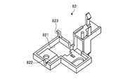
- the mounting base 82 is formed of a resin material and has a shutter opening 821 for allowing the shutter member 81 to pass therethrough.
- the mounting base 82 is attached to a predetermined portion of the rail base 361, the shutter member 81, the shutter main body portion 813 passes through the shutter opening 821 of the mounting base 82, and the shutter shaft portion 811 is the mounting base. It is configured by being arranged in a state of entering the mounting groove 822 of 82.
- the shutter member 81 is attached to the shutter spring 83 by interposing a shutter spring 83 as biasing means between the shutter locking piece 814 and the mounting locking piece 823 of the mounting base 82.
- the shutter main body 813 advances into the product storage passage 33a.
- the shutter main body portion 813 is advanced between the foremost product in the product storage passage 33a in the rear region of the sub-gate member 52 and the second product adjacent to the rear of the foremost product, and the contact portion 812. Is located below the first engagement piece 513 of the main gate member 51.
- Such a shutter member 81 normally restricts the second product from moving to the downstream side by being urged by the shutter spring 83 to advance into the product storage passage 33a. Thereby, it can prevent that the load of the goods after the 2nd goods acts on the forefront goods.
- the shutter member 81 is rotatably provided in such a manner that the shutter member 81 moves forward and backward with respect to the product storage passage 33a, and is normally urged by the shutter spring 83 to advance into the product storage passage 33a and enter the second product.
- the urging force of the shutter spring 83 is brought into contact with the main gate member 51.
- the second product is allowed to move downstream from the product storage passage 33a against this.
- the shutter member 81 restricts the second product from moving downstream, it is possible to prevent the load after the second product from acting on the most downstream product.
- the pressing portion 529 of the sub-gate member 52 is in contact with the most downstream product, which is the most downstream product, when advancing into the product storage passage 33a. When advancing into the product storage passage, it is not necessary to contact the most downstream product.
- the vending machine is described in which the input processing unit 10 includes the money processing device 16 and the coins are inserted to perform the sales process.
- the vending machine to which the product storage device according to the present invention is applied As shown in FIG. 39, the main body cabinet 1 is provided with a reader / writer unit 19 without providing an input processing unit, and a predetermined card is inserted into the reader / writer unit 19 to carry out a product sales process. It may be a thing.
- the rack selection button 13 is provided, for example, at a predetermined position on the upper front portion of each stage of the product racks 30a to 30d in the main body cabinet 1, and the mode selection button 14 is set to the lowermost stage. You may make it provide in the predetermined position of the downward side front part of the product rack 30d. According to such a configuration, the input processing unit is not necessary, and it is possible to save the space of the vending machine.
Landscapes
- Physics & Mathematics (AREA)
- General Physics & Mathematics (AREA)
- Vending Machines For Individual Products (AREA)
- Control Of Vending Devices And Auxiliary Devices For Vending Devices (AREA)
Abstract
Description
2 外扉
20 商品収納装置
30a 商品ラック
30b 商品ラック
30c 商品ラック
30d 商品ラック
31 ラック支持側板
33 商品収納コラム
33a 商品収納通路
34 レール部材
342 前端レール部
342L 左側前端レール部
342R 右側前端レール部
3421 前端左基部
3421a 左側前端縁端部
3422 前端右基部
3422a 右側前端縁端部
3421a1 左側隆起部
3421a2 左側長孔部
3421a3 左側突起部
3422a1 右側隆起部
3422a2 右側長孔部
3422a3 右側突起部
40 ラック選択機構
41 支持ロッド
43 切替カム部材
50 取出機構
51 メインゲート部材
511 第1基端部
512 第1先端部
52 サブゲート部材
521 第2基端部
522 第2先端部
529 押圧部
529a 第1押圧面
529b 第2押圧面
53 ゲート軸部
54 ゲートバネ部材
55 コイルバネ部材
60 支持機構
61 固定板
62 スライド板
63 ロック部材
70 規制機構
71 ガイド部材
711 駒部材
72 第1リンク部材
73 第2リンク部材
74 リンクスライド部材
100 制御手段
M モータ
Claims (8)
- 商品収納通路に商品を一列に並ぶよう収納する複数の商品収納コラムを並設して成る商品ラックを備えた商品収納装置であって、
前記商品収納コラム毎において商品収納通路に対して進退移動する態様で回動可能に設けられ、常態においては前記商品収納通路に進出した状態に保持されて最下流商品の下流側に位置する一方、前記商品収納通路に進出した状態に保持されることが解除されて該商品収納通路から退避する場合には、該最下流商品が取出操作されて取り出されることを許容するメインゲート部材と、
前記商品収納コラムの並設方向に沿って延在するガイド部材と、前記ガイド部材の収容域に該ガイド部材の延在方向に沿ってスライド移動可能に収容された複数の駒部材とを有して成り、常態においては、前記収容域に調整部材を進入させることにより該収容域におけるスペースの合計幅を前記メインゲート部材の進入可能部位の幅よりも小さくしてすべてのメインゲート部材が商品収納通路から退避することを規制する一方、該商品ラックにおける商品の取り出しが許容される場合には、前記収容域から前記調整部材を離脱させることにより該収容域のスペースの合計幅を前記進入可能部位の幅よりも大きくしていずれか1つのメインゲート部材が商品収納通路から退避することを許容し、かつ他のメインゲート部材が商品収納通路から退避することを規制する規制手段と
を備えたことを特徴とする商品収納装置。 - 前記規制手段は、前記商品ラックにおける商品の補充が許容される場合には、前記ガイド部材を前記メインゲート部材における進入可能部位の回動軌跡から離脱する位置に移動させてすべてのメインゲート部材が商品収納通路から退避することを許容することを特徴とする請求項1に記載の商品収納装置。
- 前記商品収納通路に対して進退移動する態様で前記メインゲート部材に連係して回動可能に設けられ、前記メインゲート部材が前記商品収納通路に進出した状態に保持される場合には前記商品収納通路から退避する一方、前記メインゲート部材が前記商品収納通路から退避する場合には前記商品収納通路に進出して前記最下流商品の上流側に隣接する第2商品が下流側に移動することを規制するサブゲート部材を備え、
前記サブゲート部材は、前記商品収納通路に進出する場合に、上部が上流側に傾倒した姿勢となって取り出される前記最下流商品に当接して該最下流商品を下流側に向けて押圧する押圧部を備えたことを特徴とする請求項1又は請求項2に記載の商品収納装置。 - 前記サブゲート部材の押圧部は、該サブゲート部材が前記商品収納通路から退避する場合に、前記最下流商品に当接することを特徴とする請求項3に記載の商品収納装置。
- 前記商品収納コラムは、前記商品収納通路に沿って延在し、かつ蓋体が着脱可能に取り付けられる蓋取付部から胴体部までの間に括れ部分を有する商品の該蓋取付部を支持することで該商品を起立姿勢に吊り下げた状態で支持するレール部材を備え、
前記レール部材は、下流側端部が下流に向かうに連れて漸次下方に傾斜する態様で湾曲して成ることを特徴とする請求項1~4のいずれか一つに記載の商品収納装置。 - 前記下流側端部は、前記括れ部分よりも幅狭となる規制部を備え、
前記規制部は、常態においては前記最下流商品が下流側に向けて通過することを規制する一方、前記最下流商品が取出操作される場合には、該最下流商品に押圧されることで前記括れ部分よりも幅広となるよう弾性変形して該最下流商品の通過を許容することを特徴とする請求項5に記載の商品収納装置。 - 前記レール部材は、
上流側から下流側に向けて前記商品を略水平に吊り下げた状態で支持する金属製のレール基体と、
前記下端側端部を構成し、かつ前記レール基体の下端部に取り付けられた左右一対の樹脂製の下端レール部と
を備え、
前記下端レール部は、それぞれが前記レール基体に対して上下方向に沿って弾性変位可能に配設してあることを特徴とする請求項5に記載の商品収納装置。 - 前記商品収納通路に対して進退移動する態様で回動可能に設けられ、常態においては付勢手段に付勢されることで前記商品収納通路に進出して前記第2商品が下流側に移動することを規制する一方、前記メインゲート部材が前記商品収納通路から退避する場合には、自身の当接部が該メインゲート部材に当接されることで前記付勢手段の付勢力に抗して前記商品収納通路から退避して前記第2商品が下流側に移動することを許容するシャッタ部材を備えたことを特徴とする請求項3~7のいずれか一つに記載の商品収納装置。
Priority Applications (6)
| Application Number | Priority Date | Filing Date | Title |
|---|---|---|---|
| MX2015001875A MX356733B (es) | 2012-09-18 | 2013-09-12 | Aparato de almacenamiento de productos. |
| US14/419,599 US9501889B2 (en) | 2012-09-18 | 2013-09-12 | Product storage device |
| JP2014536816A JP5825442B2 (ja) | 2012-09-18 | 2013-09-12 | 商品収納装置 |
| BR112015002409A BR112015002409A2 (pt) | 2012-09-18 | 2013-09-12 | dispositivo de armazenamento de produto |
| CN201380042681.1A CN104541310B (zh) | 2012-09-18 | 2013-09-12 | 商品收纳装置 |
| PH12015500199A PH12015500199B1 (en) | 2012-09-18 | 2015-01-29 | Product storage device |
Applications Claiming Priority (4)
| Application Number | Priority Date | Filing Date | Title |
|---|---|---|---|
| JP2012-204540 | 2012-09-18 | ||
| JP2012204540 | 2012-09-18 | ||
| JP2013129535 | 2013-06-20 | ||
| JP2013-129535 | 2013-06-20 |
Publications (1)
| Publication Number | Publication Date |
|---|---|
| WO2014046015A1 true WO2014046015A1 (ja) | 2014-03-27 |
Family
ID=50341329
Family Applications (1)
| Application Number | Title | Priority Date | Filing Date |
|---|---|---|---|
| PCT/JP2013/074745 Ceased WO2014046015A1 (ja) | 2012-09-18 | 2013-09-12 | 商品収納装置 |
Country Status (7)
| Country | Link |
|---|---|
| US (1) | US9501889B2 (ja) |
| JP (1) | JP5825442B2 (ja) |
| CN (1) | CN104541310B (ja) |
| BR (1) | BR112015002409A2 (ja) |
| MX (1) | MX356733B (ja) |
| PH (1) | PH12015500199B1 (ja) |
| WO (1) | WO2014046015A1 (ja) |
Cited By (1)
| Publication number | Priority date | Publication date | Assignee | Title |
|---|---|---|---|---|
| WO2017022441A1 (ja) * | 2015-08-04 | 2017-02-09 | 富士電機株式会社 | 商品収納装置及び自動販売機 |
Families Citing this family (2)
| Publication number | Priority date | Publication date | Assignee | Title |
|---|---|---|---|---|
| JP7375414B2 (ja) * | 2019-09-26 | 2023-11-08 | 富士電機株式会社 | 商品収納装置 |
| JP2022177513A (ja) * | 2021-05-18 | 2022-12-01 | 富士電機株式会社 | 商品収納ラック及び商品収納装置 |
Citations (2)
| Publication number | Priority date | Publication date | Assignee | Title |
|---|---|---|---|---|
| JP2002092725A (ja) * | 2000-09-20 | 2002-03-29 | Fuji Electric Co Ltd | 自動販売機 |
| JP2011039640A (ja) * | 2009-08-07 | 2011-02-24 | Fuji Electric Retail Systems Co Ltd | 自動販売機の商品収納装置 |
Family Cites Families (16)
| Publication number | Priority date | Publication date | Assignee | Title |
|---|---|---|---|---|
| JPS5557991A (en) * | 1978-10-24 | 1980-04-30 | Fuji Electric Co Ltd | Merchandise discharge control unit in bottle release type vending machine |
| US4705158A (en) * | 1986-12-31 | 1987-11-10 | Sun Chemical Corporation | Cup feed apparatus |
| US5209358A (en) * | 1992-06-08 | 1993-05-11 | Azbar Inc. | Bottle dispensing rack for bar |
| US5586687A (en) * | 1995-02-16 | 1996-12-24 | The Mead Corporation | Gravity feed bottle dispensing device having a track-blocking gate mechanism |
| CA2143562A1 (en) * | 1995-02-28 | 1996-08-29 | Claude Brousseau | Gravity fed bottle dispensing and display rack |
| US5788091A (en) * | 1996-02-16 | 1998-08-04 | The Mead Corporation | Article-dispensing system having an attraction device |
| US5706957A (en) * | 1996-03-18 | 1998-01-13 | Rtc Industries, Inc. | Gravity feed track system |
| US5718341A (en) * | 1996-08-22 | 1998-02-17 | Robertson; James David | Merchandising track device having billboard clip |
| NO302793B1 (no) * | 1997-04-01 | 1998-04-27 | Norcool As | Utdeleranordning for beholdere og anvendelse av anordningen |
| JP2001515251A (ja) * | 1997-09-03 | 2001-09-18 | エアゲイト・ソーシング・アンド・サプライ・プロプライエタリー・リミテッド | 自動販売機 |
| US5947303A (en) * | 1998-03-27 | 1999-09-07 | Rhc/ Spacemaster Corporation | Display and dispensing system for bottles |
| US6523719B2 (en) * | 2000-12-04 | 2003-02-25 | True Manufacturing Co., Inc. | Container dispenser for merchandiser |
| JP4379324B2 (ja) | 2004-12-09 | 2009-12-09 | 富士電機リテイルシステムズ株式会社 | 自動販売機 |
| WO2012124192A1 (ja) * | 2011-03-16 | 2012-09-20 | 富士電機リテイルシステムズ株式会社 | 自動販売機 |
| JP5810785B2 (ja) | 2011-09-16 | 2015-11-11 | 富士電機株式会社 | 商品収納装置 |
| TWI526888B (zh) * | 2011-12-20 | 2016-03-21 | 友達光電股份有限公司 | 自動販賣機及其操作系統與操作方法 |
-
2013
- 2013-09-12 CN CN201380042681.1A patent/CN104541310B/zh not_active Expired - Fee Related
- 2013-09-12 MX MX2015001875A patent/MX356733B/es active IP Right Grant
- 2013-09-12 BR BR112015002409A patent/BR112015002409A2/pt not_active Application Discontinuation
- 2013-09-12 WO PCT/JP2013/074745 patent/WO2014046015A1/ja not_active Ceased
- 2013-09-12 US US14/419,599 patent/US9501889B2/en not_active Expired - Fee Related
- 2013-09-12 JP JP2014536816A patent/JP5825442B2/ja active Active
-
2015
- 2015-01-29 PH PH12015500199A patent/PH12015500199B1/en unknown
Patent Citations (2)
| Publication number | Priority date | Publication date | Assignee | Title |
|---|---|---|---|---|
| JP2002092725A (ja) * | 2000-09-20 | 2002-03-29 | Fuji Electric Co Ltd | 自動販売機 |
| JP2011039640A (ja) * | 2009-08-07 | 2011-02-24 | Fuji Electric Retail Systems Co Ltd | 自動販売機の商品収納装置 |
Cited By (4)
| Publication number | Priority date | Publication date | Assignee | Title |
|---|---|---|---|---|
| WO2017022441A1 (ja) * | 2015-08-04 | 2017-02-09 | 富士電機株式会社 | 商品収納装置及び自動販売機 |
| CN107710289A (zh) * | 2015-08-04 | 2018-02-16 | 富士电机株式会社 | 商品收纳装置和自动售货机 |
| JPWO2017022441A1 (ja) * | 2015-08-04 | 2018-04-12 | 富士電機株式会社 | 商品収納装置及び自動販売機 |
| US10657508B2 (en) | 2015-08-04 | 2020-05-19 | Fuji Electric Co., Ltd. | Product storage device and automatic vending machine |
Also Published As
| Publication number | Publication date |
|---|---|
| US20150213669A1 (en) | 2015-07-30 |
| BR112015002409A2 (pt) | 2017-07-04 |
| CN104541310A (zh) | 2015-04-22 |
| PH12015500199A1 (en) | 2015-03-16 |
| JP5825442B2 (ja) | 2015-12-02 |
| CN104541310B (zh) | 2017-05-17 |
| PH12015500199B1 (en) | 2015-03-16 |
| MX356733B (es) | 2018-06-12 |
| MX2015001875A (es) | 2015-05-07 |
| JPWO2014046015A1 (ja) | 2016-08-18 |
| US9501889B2 (en) | 2016-11-22 |
Similar Documents
| Publication | Publication Date | Title |
|---|---|---|
| KR101387222B1 (ko) | 자동 판매기 | |
| JP5825442B2 (ja) | 商品収納装置 | |
| JP5895766B2 (ja) | 商品収納装置 | |
| JP5668545B2 (ja) | 商品収納装置 | |
| JP5810785B2 (ja) | 商品収納装置 | |
| JP5754552B2 (ja) | 商品収納装置 | |
| JP5810786B2 (ja) | 商品収納装置 | |
| JP5742328B2 (ja) | 商品収納装置 | |
| JP5842221B2 (ja) | 商品収納装置 | |
| JP5668546B2 (ja) | 商品収納装置 | |
| JP5691963B2 (ja) | 自動販売機 | |
| JP2013065192A (ja) | 自動販売機 | |
| WO2017022442A1 (ja) | 商品収納装置 | |
| JP2013065183A (ja) | 自動販売機 | |
| JP5440102B2 (ja) | 自動販売機 | |
| JP2013065184A (ja) | 自動販売機 | |
| JP2013065175A (ja) | 自動販売機 | |
| JP2013065173A (ja) | 商品収納装置 | |
| JP5375530B2 (ja) | 自動販売機 | |
| JP5434487B2 (ja) | 自動販売機 |
Legal Events
| Date | Code | Title | Description |
|---|---|---|---|
| 121 | Ep: the epo has been informed by wipo that ep was designated in this application |
Ref document number: 13838834 Country of ref document: EP Kind code of ref document: A1 |
|
| ENP | Entry into the national phase |
Ref document number: 2014536816 Country of ref document: JP Kind code of ref document: A |
|
| WWE | Wipo information: entry into national phase |
Ref document number: 12015500199 Country of ref document: PH |
|
| WWE | Wipo information: entry into national phase |
Ref document number: 14419599 Country of ref document: US |
|
| WWE | Wipo information: entry into national phase |
Ref document number: MX/A/2015/001875 Country of ref document: MX |
|
| NENP | Non-entry into the national phase |
Ref country code: DE |
|
| REG | Reference to national code |
Ref country code: BR Ref legal event code: B01A Ref document number: 112015002409 Country of ref document: BR |
|
| 122 | Ep: pct application non-entry in european phase |
Ref document number: 13838834 Country of ref document: EP Kind code of ref document: A1 |
|
| ENP | Entry into the national phase |
Ref document number: 112015002409 Country of ref document: BR Kind code of ref document: A2 Effective date: 20150203 |