WO2014045991A1 - 加湿器 - Google Patents
加湿器 Download PDFInfo
- Publication number
- WO2014045991A1 WO2014045991A1 PCT/JP2013/074644 JP2013074644W WO2014045991A1 WO 2014045991 A1 WO2014045991 A1 WO 2014045991A1 JP 2013074644 W JP2013074644 W JP 2013074644W WO 2014045991 A1 WO2014045991 A1 WO 2014045991A1
- Authority
- WO
- WIPO (PCT)
- Prior art keywords
- water
- air
- filter
- humidifier
- housing
- Prior art date
- Legal status (The legal status is an assumption and is not a legal conclusion. Google has not performed a legal analysis and makes no representation as to the accuracy of the status listed.)
- Ceased
Links
Images







Classifications
-
- F—MECHANICAL ENGINEERING; LIGHTING; HEATING; WEAPONS; BLASTING
- F24—HEATING; RANGES; VENTILATING
- F24F—AIR-CONDITIONING; AIR-HUMIDIFICATION; VENTILATION; USE OF AIR CURRENTS FOR SCREENING
- F24F6/00—Air-humidification, e.g. cooling by humidification
- F24F6/02—Air-humidification, e.g. cooling by humidification by evaporation of water in the air
- F24F6/04—Air-humidification, e.g. cooling by humidification by evaporation of water in the air using stationary unheated wet elements
- F24F6/043—Air-humidification, e.g. cooling by humidification by evaporation of water in the air using stationary unheated wet elements with self-sucking action, e.g. wicks
-
- F—MECHANICAL ENGINEERING; LIGHTING; HEATING; WEAPONS; BLASTING
- F24—HEATING; RANGES; VENTILATING
- F24F—AIR-CONDITIONING; AIR-HUMIDIFICATION; VENTILATION; USE OF AIR CURRENTS FOR SCREENING
- F24F13/00—Details common to, or for air-conditioning, air-humidification, ventilation or use of air currents for screening
- F24F13/20—Casings or covers
-
- F—MECHANICAL ENGINEERING; LIGHTING; HEATING; WEAPONS; BLASTING
- F24—HEATING; RANGES; VENTILATING
- F24F—AIR-CONDITIONING; AIR-HUMIDIFICATION; VENTILATION; USE OF AIR CURRENTS FOR SCREENING
- F24F6/00—Air-humidification, e.g. cooling by humidification
- F24F2006/008—Air-humidifier with water reservoir
Definitions
- the present invention relates to a humidifier that includes a humidifying filter that is partially submerged in a water storage tank, traps dust contained in air sucked from a suction port by a dust collecting filter, and ventilates the humidified filter to humidify the dust. Furthermore, the present invention relates to a humidifier that performs humidification by passing air through a humidification filter partially immersed in a water storage tank.
- the humidifier according to Patent Document 1 includes a housing having a blower outlet on the top surface and having a unit insertion opening formed from the lower side to the rear side.
- a humidification unit is detachably inserted into the unit insertion port of the housing.
- the humidifying unit closes the unit insertion port of the housing and forms a suction port for the humidifier.
- the suction port is composed of a plurality of slit holes formed on both sides of the humidifier, and a dust collecting filter for capturing dust contained in the air is provided in each slit hole.
- the humidification unit includes a water storage tank having an upper opening, a water supply tank that supplies water to the water storage tank, and a humidification filter that is submerged in water and is held so that air passes through the upper part.
- the water supply tank is a water storage tank. It is attached to the top.
- a blower is provided inside the housing, and is configured to blow in air that has been sucked in from the suction port of the humidification unit and passed through the humidification filter from the blowout port of the housing. In the humidifier configured as described above, dust in the air can be prevented from entering the housing by capturing the dust with the dust collecting filter.
- the present invention has been made in view of such circumstances, and it is an object of the present invention to provide a humidifier capable of preventing dust accumulated in a dust collection filter from being seen from the outside and preventing the dust from falling outside. To do. Further, by providing a water receiving section and a water flow groove at the bottom of the water storage tank, the amount of water stored in the water storage tank can be suppressed, and water can be supplied smoothly regardless of the inclination of the humidifier. Provide a bowl.
- the humidifier according to the present invention has a housing having an air inlet, a flow path, and an air outlet, a blower that allows air to flow through the flow path, and an upper portion that is open to humidify the air.
- a water storage tank that stores the water, a humidifying filter that is partly submerged in the water storage tank and the other part is positioned in the flow path, and an upstream side in the flow direction of the humidifying filter
- a humidifier provided with a dust collecting filter that captures dust in the air and includes a cover plate that has an insertion hole into which the part of the humidifying filter is inserted and covers the opening of the water storage tank, The dust collection filter is arranged on the upper surface side of the cover plate and in the middle of the flow path in the housing.
- the dust collection filter is disposed not inside the suction port but inside the housing, the dust accumulated in the dust collection filter is not visually recognized from the outside.
- the dust collection filter is disposed inside the housing, the dust accumulated in the dust collection filter does not fall outside the humidifier.
- the dust collection filter is arranged on the upper surface side of the cover plate that covers the opening at the top of the water storage tank, the dust accumulated in the dust collection filter falls on the upper surface of the cover plate, and the dust is stored in the water storage tank. Will not fall into the water.
- the humidifier according to the present invention is characterized in that a rib protruding upward is formed at an edge of the insertion hole.
- the cover plate covering the upper opening of the water storage tank has an insertion hole into which the humidifying filter is inserted, and a rib protruding upward is formed at the edge of the insertion hole. Therefore, even if the dust accumulated in the dust collection filter moves to the insertion hole, the dust is captured by the rib. Therefore, it is possible to effectively prevent dust from falling into the insertion hole.
- the dust collecting filter is erected on the cover plate and a filter member facing one surface through which air flows into the humidifying filter, and air flows into the humidifying filter. And a frame that surrounds the other surface and holds the filter member.
- the dust collection filter has a frame and a filter member provided on the frame, and each surface into which air flows into the humidifying filter is covered with the filter member and the frame. Yes. Therefore, the dust in the air sucked into the inside of the housing is captured at the stage before reaching the humidifying filter.
- the casing is joined to the first casing portion constituting the downstream side of the flow path, and the upstream side of the flow path.
- the suction port has a slit shape formed at a joint portion between the first housing part and the second housing part.
- air is sucked from a slit-like suction port formed at a joint portion between the first housing portion and the second housing portion constituting the housing.
- the humidifier according to the present invention includes a charged particle generation unit that is arranged in the middle of the flow path and generates charged particles, and blows out air including the charged particles generated by the charged particle generation unit from the outlet. It is characterized by the above.
- humidified air containing charged particles is blown out from the outlet.
- a humidifier includes a housing having an air inlet, a flow path, and an air outlet, a blower that allows air to flow through the flow path, and a water storage tank that stores water for humidifying the air.
- a water supply port protruding to the bottom side of the water storage tank, a water supply tank for supplying water to the water storage tank, a part of the water storage tank being submerged, and another part of the water storage tank being located in the flow path
- a water storage recess in which water for immersing the part of the humidifying filter, a water receiving groove and a water storage recess that communicate with the water storage recess, the water receiving groove and the water storage recess are connected to each other; It is provided at the periphery of the section, and introduces air from the water supply port to
- an air introduction recess is provided on the periphery of the water receiving part separately from the water flow groove. Even when the humidifier is tilted and it is difficult to introduce air from the water channel side, air is introduced into the water supply tank from the water supply port through the air introduction recess, and the air and the water in the water supply tank are introduced. And are replaced.
- the humidifier according to the present invention is characterized in that the water receiving portion is located between the air introduction recess and the water flow groove.
- the humidifier since the air introduction concave portion is provided on the opposite side of the water flow groove through the water receiving portion, the humidifier is inclined in the direction along the water flow groove and from the water flow groove side. Even when it becomes difficult to introduce air, air is introduced into the water supply tank from the water supply port through the air introduction recess on the opposite side, and the air and water in the water supply tank are replaced.
- the humidifier according to the present invention has a plurality of the air introduction recesses, the water receiving portion is circular, and the plurality of air introduction recesses and the water flow groove are arranged at the periphery of the water receiving portion, etc. It is arranged.
- the water receiving portion is circular, and a plurality of air introduction recesses and water passage grooves are equally arranged around the periphery of the water receiving portion. Therefore, even if the humidifier is inclined in the direction along the water flow groove or in other directions, air is introduced into the water supply tank from the water supply port through the air introduction recess or water flow groove, and the air and the water supply tank Water is replaced.
- the humidifier according to the present invention is characterized in that the air introduction recess has an inclined bottom that is shallower in a portion separated from the water receiving portion than a center side of the water receiving portion.
- the air introduction recess since the air introduction recess has an inclined bottom that becomes shallower as it gets away from the center of the water receiving portion, it is possible to suppress the amount of water accumulated in the air introduction recess.
- the humidifier according to the present invention includes a charged particle generation unit that is arranged in the middle of the flow path and generates charged particles, and blows out air including the charged particles generated by the charged particle generation unit from the outlet. It is characterized by the above.
- humidified air containing charged particles is blown out from the outlet.
- the dust accumulated on the dust collecting filter cannot be seen from the outside, and the dust can be prevented from falling to the outside. Furthermore, the amount of water stored in the water storage tank can be suppressed by providing a water receiving section and a water flow groove at the bottom of the water storage tank, and water can be supplied smoothly regardless of the inclination of the humidifier.
- FIG. 1 It is a perspective view which shows one structural example of a water storage tank. It is a top view which shows the example of 1 structure of a water storage tank. It is the XI-XI sectional view taken on the line of FIG. It is the perspective view which showed one structural example of the cover. It is the perspective view which showed one structural example of the dust collection filter. It is the front view which showed the example of 1 structure of the dust collection filter. It is a circuit diagram of a charged particle generation unit. It is a top view which shows the water storage tank which concerns on the modification 1. FIG. It is a top view which shows the water storage tank which concerns on the modification 2. FIG.
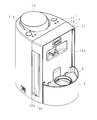
- FIG. 1 is a perspective view showing a configuration example of a humidifying blower according to the present embodiment
- FIG. 2 is a side view showing a configuration example of the humidifying blower.
- the humidifying blower according to the present embodiment has an elliptic columnar shape as a whole, and increases the amount of moisture on the skin surface and improves skin elasticity by blowing humidified air containing positively charged particles and negatively charged particles.
- a beauty instrument that can.
- the humidifying blower includes a semi-elliptical columnar casing 1 having an elliptical shape in plan view lacking one end portion in the major axis direction.
- the housing 1 has an air inlet 12a and an air outlet 11a on both side surfaces and the other end in the major axis direction of the top surface, respectively.
- a water supply tank 3 and a water storage tank 2 are arranged above and below one end of the casing 1 in the major axis direction, respectively, and the casing 1, the water storage tank 2 and the water supply tank 3 as a whole have an elliptical column shape.
- directions are determined as follows.
- the grounding surface side is directed downward, the air outlet 11a side is directed upward, the major axis direction one end side is the rear side, the major axis direction other end side is the front side, and the humidification blower is directed to the front side of the humidification fan.
- the left and right sides are defined as the left direction and the right direction.
- the left-right direction is referred to as the horizontal direction.
- FIG. 3 is a side sectional view showing an example of the configuration of the humidifying blower
- FIG. 4 is a sectional view taken along the line IV-IV in FIG. 2
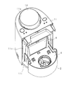
- FIG. 5 is a perspective view of the humidifying blower with the water supply tank 3 removed
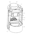
- FIG. 7 is a perspective view of the humidifying blower from which the water supply tank 3 and the second housing portion 12 are removed
- FIG. 7 is a perspective view of the humidifying blower from which the water supply tank 3 or the dust collecting filter 5 is removed
- FIG. It is a perspective view of the humidification air blower from which 4 was removed.
- arrows indicated by broken lines indicate the flow of air flowing through the flow path 10 formed inside the housing 1.
- the housing 1 is composed of a first housing portion 11 constituting the front half of the humidifying blower and a second housing portion 12 constituting the rear portion.
- the first housing portion 11 is substantially semi-elliptical in plan view, and has a partition wall 11 b that separates the internal space of the first housing portion 11 from the space formed by the second housing portion 12.
- electrical system components for generating and blowing charged particles are housed, and the interior of the second housing part 12 separated by the partition wall 11b.
- the space accommodates non-electrical components that perform humidification.
- the partition wall 11b has a rectangular recess having a vertically long rectangular shape in which a part of the humidifying filter 6 and the water storage tank 2 described later are accommodated.
- the rectangular recess is formed from the substantially vertical center of the partition wall 11b to the bottom plate.
- a flow hole 11 c for allowing air to flow from the second housing portion 12 to the first housing portion 11 is formed in a substantially central portion of the inner surface of the rectangular recess.
- the flow hole 11c is constituted by, for example, a plurality of concentric arc slits.
- a fan housing portion 11d having a substantially rectangular parallelepiped shape is formed in front of the flow hole 11c, that is, inside the first housing portion 11, and the fan 7 is housed in the fan housing portion 11d.
- the blower 7 is a sirocco fan, for example.
- the sirocco fan is constituted by a cylindrical member having blades arranged around, a motor for rotating the cylindrical member, and a rectifier.
- the air inlet of the blower 7 faces the flow hole 11c, the blower 7 sucks air through the flow hole 11c, the flow direction of the sucked air is rectified upward by the rectifier, and the air is blown upward.
- the upper portion of the fan accommodating portion 11d is open and communicates with the charged particle generating chamber 11f having a rectangular cylindrical shape through the branch channel 11e.
- the branch flow path 11e the flow of air blown from the blower 7 is passed through a first path that leads to a location where positively charged particles are generated and a second path that leads to a location where negatively charged particles are generated.
- a diversion plate 13 for diversion is provided.
- the diversion plate 13 is a plate member that horizontally separates the diversion channel 11e, and diverts the air blown from the blower 7 to a path on the left side of the diversion channel 11e and a path on the right side of the diversion channel 11e. To do.
- a unit holding part 11h for holding the charged particle generating unit 8 for generating charged particles is provided behind the charged particle generating chamber 11f.
- the unit holding part 11h has a substantially rectangular tube shape with both front and rear ends opened.
- the rear opening of the unit holding part 11h is formed above the rectangular recess of the partition wall 11b, and functions as an insertion port into which the charged particle generating unit 8 is inserted so as to be detachable from the rear.
- the opening in front of the unit holding part 11h is formed in the rear surface of the charged particle generation chamber 11f, and the front part of the charged particle generation unit 8 held in the unit holding part 11h is exposed to the charged particle generation chamber 11f. . As shown in FIG.
- a positive electrode needle 86 that generates positively charged particles and a negative electrode needle 87 that generates negatively charged particles are provided in the front portion of the charged particle generating unit 8 in a lateral direction. . That is, the positive electrode needle 86 and the negative electrode needle 87 of the charged particle generation unit 8 are exposed to the charged particle generation chamber 11f side, and the positively charged particles and the negatively charged particles generated by the positive electrode needle 86 and the negative electrode needle 87 are charged particles, respectively. It is configured to be discharged into the generation chamber 11f.
- the charged particle generation unit 8 held in the unit holding unit 11h is connected to a control circuit board or a power supply circuit (not shown) and is supplied with power. Details of the circuit configuration of the charged particle generation unit 8 will be described later.
- the positive electrode needle 86 and the negative electrode needle 87 do not appear as cross sections, but the positions of the positive electrode needle 86 and the negative electrode needle 87 are virtually drawn to help understanding of the invention.
- a charged particle sensor 9 for detecting the concentration of the charged particles is provided above the positive electrode needle 86 and the negative electrode needle 87 of the charged particle generation unit 8 and in the front part of the charged particle generation chamber 11f. .
- the charged particle sensor 9 is connected to a control circuit board (not shown), and the control circuit manages the operation state of the charged particle generation unit 8, the replacement time of the charged particle generation unit 8, and the like.
- the charged particle generation chamber 11 f is disposed between the charged particle sensor 9 and the charged particle generation unit 8, and a suppression plate 91 that suppresses the diffusion of the charged particles from the charged particle generation unit 8 to the charged particle sensor 9. Is arranged.
- the suppression plate 91 includes an upper suppression plate 91a and a lower suppression plate 91b that are positioned above and below the charged particle generation chamber 11f, respectively.
- the upper restraining plate 91a has a horizontally long rectangular shape and is positioned closer to the lateral positive electrode needle 86. More specifically, the lateral width of the upper restraining plate 91a is substantially half of the lateral width of the charged particle generation chamber 11f, and the lateral position of one short side substantially coincides with the lateral position of the upper end portion of the flow dividing plate 13. The air flow path on the positive electrode needle 86 side is separated forward and backward.
- the upper restraining plate 91a has rectangular cutout portions 91c at both ends of the lower long side.
- the lower restraining plate 91b has a horizontally long rectangle, and is arranged so that the upper side substantially contacts the lower side of the upper restraining plate 91a. More specifically, the lateral width of the upper restraining plate 91a is substantially the same as the lateral width of the charged particle generation chamber 11f, and the lower side is located at the upper end portion of the flow dividing plate 13 and faces the positive electrode needle 86 and the negative electrode needle 87. . Moreover, a downward concave cutout is provided at the lower portion of the substantially central portion in the horizontal direction of the lower restraining plate 91b.
- the position of the upper end of the notch is substantially the same as the vertical position of the positive electrode needle 86 and the negative electrode needle 87, and the lateral width of the notch is approximately one third of the distance between the positive electrode needle 86 and the negative electrode needle 87.
- the notch is in a lateral position at a substantially central portion between the positive electrode needle 86 and the negative electrode needle 87, one lateral end is located at the upper end portion of the flow dividing plate 13, and the other end is the positive electrode needle of the charged particle generating chamber 11f. Located near 86.
- the charged particle sensor 9 is located near the lateral positive electrode needle 86 and in front of the upper suppression plate 91a. Further, the charged particle sensor 9 has a positively charged particle sensor unit 9 a corresponding to a sensing part that captures positively charged particles above the positive electrode needle 86.
- the charged particle generation chamber 11f is open at the top and communicates with the air outlet 11a.
- a plurality of rectifying plates 11g are juxtaposed in the lateral direction at the opening above the charged particle generation chamber 11f.
- a disc-shaped wind direction plate 14 is provided at the air outlet 11a so as to be able to be lifted and lowered. By raising the wind direction plate 14, the wind direction blown out from the air outlet 11a can be changed.
- casing part 11 protrudes back from the lower end part, and has the baseplate part 11i in which the water tank 2 is mounted.
- the bottom plate portion 11i is provided with a water tank locking claw 11j that locks the bottom of the water tank 2 placed on the bottom plate portion 11i.
- the second housing part 12 covers the rear part of the first housing part 11 so as to take in the front part of the water storage tank 2 placed on the bottom plate part 11i of the first housing part 11, thereby providing a humidified space.
- casing part 12 is comprised by the vertical side wall 12b which has the blower outlet 11a, the housing
- the blower outlet 11 a has a single slit shape formed over the upper and lower portions of the side wall 12 b, and is formed at a joint portion between the first housing portion 11 and the second housing portion 12.
- the air outlet 11 a is curved inward in the lateral direction so that a gap is formed between the front end portion of the side wall 12 b constituting the second housing portion 12 and the first housing portion 11. It is constituted by a curved plate.
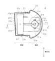
- FIG. 10 is a plan view showing a configuration example of the water storage tank 2
- FIG. 11 is a cross-sectional view taken along the line XI-XI of FIG.
- the water reservoir 2 is open at the top and stores water for humidifying the air.
- the water storage tank 2 is configured by a rectangular front portion taken into the housing 1 and a rear semicircular arc shape protruding rearward from the housing 1. ing.
- the water storage tank 2 includes a bottom portion 21 having such a planar shape, and a water storage wall 22 surrounding the periphery of the bottom portion 21.
- the bottom portion 21 has a bottom surface 21a having a rectangular shape in plan view in which a water receiving portion 21b and a water flow groove 21e described later are formed.
- the bottom surface 21 a is formed in a substantially central portion in the lateral direction from the rear end portion to the middle of the front portion, and has a lateral width that is appropriately separated from the water storage wall 22.
- a filter fitting recess 21f (water storage recess) having a rectangular shape in plan view is formed in front of the bottom surface 21a, that is, at the front end portion of the water storage tank 2, and the lower portion of the substantially rectangular parallelepiped humidification filter 6 is fitted therein.
- the filter fitting recess 21f is formed across the lateral ends and is deeper than the bottom surface 21a.
- the shape of the filter fitting recess 21f does not necessarily need to be a shape in which the lower portion of the humidifying filter 6 is fitted, and may be at least a concave shape in which water that soaks the lower portion of the humidifying filter 6 is accumulated.
- the upper stage bottom face part 21g higher than the bottom face 21a is formed over the inner periphery of the water storage wall 22.
- the upper bottom portion 21g is a structure for supporting the cover 4 described later and preventing water from overflowing when the humidifying blower is tilted.
- a water receiving portion 21 b that receives water supplied from the water supply tank 3 is formed on the rear portion of the bottom surface 21 a of the water storage tank 2.
- the water supply tank 3 includes a tank body 31 having a semi-cylindrical shape that is substantially the same as the water tank 2 in plan view, and a water supply port 32 that protrudes downward from the tank body 31.
- the water supply port 32 is screwed into the tank body 31, and an open / close bar 33 for opening and closing the water supply port 32 is provided so as to be able to advance and retreat.
- the opening / closing bar 33 is biased in a closing direction by a biasing means (not shown), and the water supply port 32 is configured to open by pushing the opening / closing bar 33 against the biasing force.
- the water receiving portion 21 b is a circular recess formed along the edge of the water supply port 32 of the water supply tank 3. That is, the water receiving portion 21 b is a circular recess that is slightly larger than the water supply port 32.
- the center of the water receiving portion 21b is located at a substantially central portion in the lateral direction of the water storage tank 2, and a water receiving rod 21c for opening the water supply port 32 protrudes upward at the center of the water receiving portion 21b.
- a water passage groove 21e is formed in the bottom surface 21a of the water storage tank 2 so that the water receiving portion 21b and the filter fitting recess 21f communicate with each other and the water received by the water receiving portion 21b flows into the filter fitting recess 21f.
- the water flow groove 21 e is a straight line that is long in the front-rear direction, and is formed at the substantially central portion in the lateral direction of the water tank 2.
- the water flow groove 21e is inclined so that the filter fitting recess 21f side is deeper than the water receiving part 21b side. Furthermore, a plurality of air introduction recesses 21 d for introducing air from the water supply port 32 to the water supply tank 3 at the time of water supply are provided at the periphery of the water receiving portion 21 b. For example, as shown in FIG. 10, three air introduction recesses 21d and a water flow groove 21e are equally arranged on the periphery of the water receiving portion 21b. That is, the water flow groove 21e is located on the front side of the water receiving portion 21b, and the three air introduction recesses 21d are located on both lateral sides and the rear side of the water receiving portion 21b.
- the air introduction recess 21d has an inclined bottom formed so that the outer side in the radial direction is shallower than the center of the water receiving portion 21b.
- the width of the air introduction recess 21d in the circumferential direction and the radial direction of the water receiving portion 21b is approximately the same as that of the water flow groove 21e.
- the dimensions of the air introduction recess 21d are not particularly limited as long as the air can be introduced into the water supply tank 3 even when the humidifying blower is tilted. However, in order to reduce the amount of water that overflows from the water storage tank 2 when the humidifying blower falls, it is desirable that the air introduction recess 21d be configured with a minimum dimension capable of introducing air.
- the water storage wall 22 has a rear wall 22a in a plan view arc shape that constitutes the rear portion, side walls 22b and 22c that constitute the front portion, and an opposing wall 22d that faces the partition wall 11b of the first housing portion 11.
- the opposing wall 22d is a leakage portion that leaks stored water to the outside from the portion of the opposing wall 22d that does not face the flow hole 11c when the water storage tank 2 is tilted toward the flow hole 11c of the partition wall 11b.
- a stepped portion 22f is formed on the upper portion of the opposing wall 22d and protrudes forward, and an inclined wall portion 22e that obliquely faces the partition wall 11b in a plan view is provided on the opposing wall 22d. Yes.
- the stepped portion 22f is configured such that the front side is higher than the rear side.
- One end in the horizontal direction of the inclined wall portion 22e is in contact with the partition wall 11b.
- the one end portion is in contact with the partition wall 11b and functions as a contact portion for suppressing the play of the water storage tank 2.
- the one end part of the inclined wall part 22e is formed with a leakage recess 22g for transferring the stored water to the outside of the water storage tank 2 and effectively leaking it.
- the structure for transmitting the water in the water storage tank 2 to the outside of the water storage tank 2 is not limited to the concave shape, and may be a convex portion.
- FIG. 12 is a perspective view showing a configuration example of the cover 4.
- the humidification blower includes a cover 4 that covers the opening of the water storage tank 2 and holds the humidification filter 6 and the dust collection filter 5.
- the cover 4 includes a cover plate 41 formed following the opening of the water storage tank 2.
- the cover plate 41 has a rectangular shape in plan view at the front and a semicircular shape in plan view at the rear as in the water tank 2.
- the cover plate 41 includes a peripheral wall 41 a that protrudes downward from the peripheral edge, and the peripheral wall 41 a is supported by the upper bottom surface portion 21 g of the water storage tank 2.
- a flange 41b protruding outward from the peripheral wall 41a is formed at the peripheral edge of the cover plate 41 to prevent leakage of water from the water storage tank 2.
- a water supply port insertion hole 42 into which the water supply port 32 of the water storage tank is inserted is formed in the rear portion of the cover plate 41. Further, a filter insertion hole 43 into which the lower part of the humidifying filter 6 is inserted is formed in the front part of the cover plate 41.
- the filter insertion hole 43 has a horizontally long rectangular shape in plan view, and a rib 44 protruding upward is formed at the edge of the long side.
- a filter holding wall 45 that holds the humidifying filter 6 inserted into the filter insertion hole 43 is erected on both short sides of the filter insertion hole 43. The upper ends of the filter holding walls 45 erected on each short side are connected by a horizontally long upper plate 46.
- a filter locking projection 46 a for fixing the dust collection filter 5 is provided at a substantially central portion in the horizontal direction of the rear long side of the upper plate 46. Further, a filter locking hole 47 for fixing the dust collecting filter 5 is formed in the cover plate 41 behind the filter insertion hole 43. Further, a holding portion 48 that holds the lower end portion of the housing rear surface wall 12 d of the second housing portion 12 is provided at a boundary portion between the front portion and the rear portion of the cover plate 41.
- FIG. 13 is a perspective view illustrating a configuration example of the dust collection filter 5
- FIG. 14 is a front view illustrating a configuration example of the dust collection filter 5.
- a dust collection filter 5 is disposed on the upper surface side of the cover plate 41.
- the dust collection filter 5 includes a filter member 52 that captures dust in the air, and a frame 51 that holds the filter member 52 and surrounds both side surfaces and the upper surface side of the humidifying filter 6.
- the frame body 51 includes a frame body side surface portion 51a that covers the filter holding wall 45 from the outside in the lateral direction, a frame body top surface portion 51b that covers the upper side of the upper plate 46, and a rear side of the frame body side surface portion 51a and the frame body top surface portion 51b.
- the lattice frame 51c is comprised with the lattice frame 51c provided in the edge continuously.
- the lattice frame 51 c is provided with a filter member 52, and the rear surface side of the humidifying filter 6 is covered with the filter member 52.
- a locking projection fitting hole 51d into which the filter locking projection 46a is fitted is formed at a substantially central portion in the horizontal direction of the frame body top surface portion 51b.
- a filter locking claw 51e that is locked to the filter locking hole 47 is provided at a lower portion of the lattice frame 51c and at a substantially central portion in the horizontal direction.
- the dust retaining filter 5 is put on the filter holding wall 45 and the upper plate 46, the filter locking projection 46a of the upper plate 46 is fitted into the locking projection fitting hole 51d, and the filter locking claw 51e is fitted into the filter locking hole 47.
- the dust collecting filter 5 can be installed on the cover plate 41 by being inserted into and locked. Since the frame side surface portion 51a and the frame body top surface portion 51b of the dust collection filter 5 erected on the cover plate 41 are in contact with the housing rear wall 12d, and the lower side of the lattice frame 51c is also in contact with the cover plate 41. Dust can be prevented from flowing into the housing 1 through the humidifying filter 6.
- FIG. 15 is a circuit diagram of the charged particle generation unit 8.
- the charged particle generation unit 8 has a connection end 81 for connection to a control circuit board (not shown).
- the connection end 81 of the charged particle generation unit 8 is connected to a DC / AC conversion circuit 82 that converts a DC voltage input to the connection end 81 into an AC voltage.
- a primary coil of the high voltage transformer 83 is connected to the output end of the DC / AC conversion circuit 82, and an AC voltage is applied to the primary coil.
- a rectifier diode 84 is connected in sequence to one end of the secondary coil of the high-voltage transformer 83, and a positive electrode needle 86 is connected to the cathode of the rectifier diode 84.
- a rectifier diode 85 is reversely connected to the other end of the secondary coil of the high-voltage transformer 83, and a negative electrode needle 87 is connected to the cathode of the rectifier diode 85.
- the charged particle generation unit 8 has a ground plate 88 that is grounded by being connected to the circuit board.
- the ground plate 88 has holes that are appropriately spaced apart from each other, and the ground plate 88, the positive electrode needle 86, and the negative electrode needle 87 are positioned so that the tips of the positive electrode needle 86 and the negative electrode needle 87 are located at the center of each hole. It is fixed.
- the dust collection filter 5 is disposed inside the housing 1, and therefore dust collected in the dust collection filter 5 is prevented from being visually recognized from the outside of the housing 1. Can do. In addition, the dust can be prevented from falling outside the humidifying blower.
- the dust collection filter 5 is erected on the upper surface side of the cover plate 41 that covers the upper portion of the water storage tank 2, dust collected in the dust collection filter 5 is prevented from falling onto the water surface of the water storage tank 2. be able to.
- the rib 44 is provided at the edge of the filter insertion hole 43 formed in the cover plate 41, even if the dust adhering to the cover plate 41 moves toward the filter insertion hole 43, the dust is the rib 44. To be captured. Therefore, dust can be more effectively prevented from falling on the water surface of the water storage tank 2.
- the humidifying filter 6 covers the entire rear surface and peripheral edge by the filter member 52 and the frame 51 of the dust collecting filter 5, the dust in the air sucked into the housing 1 reaches the humidifying filter 6. Captured before. Therefore, it is possible to effectively prevent dust in the air from entering the components where humidification, air blowing, and generation of charged particles are performed.
- the suction port 12a is a single slit formed at the joint portion between the first housing portion 11 and the second housing portion 12 over the top and bottom, it is configured by a plurality of small slit holes. As compared with the slit hole, the air flow resistance can be reduced, and even a small humidified blower can effectively suck air and blow humidified air containing charged particles.
- the amount of water stored in the water storage tank 2 can be suppressed by providing the water receiving part 21b and the water flow groove 21e at the bottom 21 of the water storage tank 2, and smooth water supply is possible regardless of the inclination of the humidifying blower. Can be done.
- the air introduction recess 21d is provided at the periphery of the water receiving portion 21b, even if the humidifier is inclined and it is difficult to introduce air from the water flow groove 21e side, the air introduction recess is provided. Air is introduced into the water supply tank 3 from the water supply port 32 through 21d, and water supply can be performed smoothly.
- the humidifier is in any of the front, rear, left and right directions. Even if it inclines in the direction, air is introduced into the water supply tank 3 from the water supply port 32 through the air introduction recess 21d or the water flow groove 21e, and water can be supplied smoothly.
- the air introduction recessed portion 21d has an inclined bottom that becomes shallower as it is away from the center of the water receiving portion 21b, the amount of water accumulated in the air introduction recessed portion 21d can be suppressed, and the amount of water that overflows during a fall is reduced. can do.
- FIG. 16 is a plan view showing the water storage tank 102 according to the first modification. Similar to the embodiment, the water storage tank 102 according to Modification 1 includes a bottom portion 21 and a water storage wall 22, and a water receiving portion 21b is formed on the bottom surface 21a. In the water receiving portion 21b, two air introduction concave portions 21d are arranged in three parts together with the water flow groove 21e. That is, the water flow groove 21e and the two air introduction recesses 21d are provided on the periphery of the water receiving portion 21b with an interval of 120 degrees.
- the humidifying blower provided with the two air introduction recesses 21d even if the humidification blower is tilted forward, backward, left and right, air is supplied from either the water flow groove 21e or the two air introduction recesses 21d.
- the number of air introduction recesses 21d can be reduced, and the same effect as in the embodiment can be obtained.
- FIG. 17 is a plan view showing a water storage tank 202 according to the second modification. Similar to the embodiment, the water storage tank 202 according to the modified example 2 includes a bottom portion 21 and a water storage wall 22, and a water receiving portion 21b is formed on the bottom surface 21a. The water receiving portion 21b is provided with an arc-shaped air introducing recess 21d so as to face the water passage groove 21e. An arcuate air introduction recess 21d is provided on the rear edge of the water receiving portion 21b. The air introduction recess 21d is formed over a range of approximately 60 degrees in the left-right direction about the water receiving part 21b and 120 degrees in total.
Landscapes
- Engineering & Computer Science (AREA)
- Chemical & Material Sciences (AREA)
- Combustion & Propulsion (AREA)
- Mechanical Engineering (AREA)
- General Engineering & Computer Science (AREA)
- Air Humidification (AREA)
Abstract
集塵フィルタに溜まった塵埃が外部から見えず、該塵埃が外部に落下しない加湿器を提供する。 空気の吸込口、通流路及び吹出口11aを有する筐体と、該筐体の内部に配され、空気を前記通流路に通流させる送風機と、上部が開口しており、空気を加湿するための水を貯留する貯水槽2と、該貯水槽2に一部が浸水し、他の一部が前記通流路に位置するように配された加湿フィルタ6と、加湿フィルタ6よりも通流方向上流側に配され、空気中の塵埃を捕捉する集塵フィルタ5とを備える加湿器において、加湿フィルタ6の前記一部が挿入される挿入孔を有し、貯水槽2の開口を覆う覆板4を備え、集塵フィルタ5は覆板4の上面側であって、筐体内の通流路の途中に配されていることを特徴とする加湿器。
Description
本発明は、貯水槽に一部が浸水した加湿フィルタを備え、吸込口から吸い込んだ空気に含まれる塵埃を集塵フィルタによって捕捉し、加湿フィルタに通風して加湿を行う加湿器に関する。さらに、貯水槽に一部が浸水した加湿フィルタに通風して加湿を行う加湿器に関する。
机上に置いて使用者の周囲を加湿する小型の加湿器が提案されている(例えば、特許文献1)。特許文献1に係る加湿器は、天面に吹出口を有し、側面下部から後側にかけてユニット挿入口が形成された筐体を備える。筐体のユニット挿入口には、加湿ユニットが着脱自在に挿入される。加湿ユニットは、筐体のユニット挿入口を塞ぐとともに、加湿器の吸込口を形成している。吸込口は、加湿器の両側面に、上下にわたって形成された複数のスリット孔からなり、各スリット孔には、空気に含まれる塵埃を捕捉する集塵フィルタが設けられている。加湿ユニットは、上部が開口した貯水槽と、貯水槽に水を供給する給水タンクと、下部が浸水し、上部を空気が通過するように保持された加湿フィルタとを備え、給水タンクは貯水槽の上部に取り付けられている。筐体の内部には送風機が設けられており、加湿ユニットの吸込口から吸い込まれ、加湿フィルタを通過することによって加湿された空気を筐体の吹出口から吹き出すように構成されている。
このように構成された加湿器においては、集塵フィルタによって塵埃を捕捉することにより、空気中の塵埃が筐体内部に侵入することを防ぐことができる。
このように構成された加湿器においては、集塵フィルタによって塵埃を捕捉することにより、空気中の塵埃が筐体内部に侵入することを防ぐことができる。
しかしながら、特許文献1に係る加湿器においては、加湿器の外部から視認できる側面下部に空気吸い込み用のスリット孔が形成されているため、スリット孔の集塵フィルタに溜まった塵埃が外部から見え、見苦しいという問題があった。
また、加湿器を持ち運ぶ際、スリット孔の集塵フィルタに溜まった塵埃が机上又は床面に落下し、机又は床を汚すという問題があった。
また、加湿器を持ち運ぶ際、スリット孔の集塵フィルタに溜まった塵埃が机上又は床面に落下し、机又は床を汚すという問題があった。
本発明は斯かる事情に鑑みてなされたものであり、集塵フィルタに溜まった塵埃が外部から見えず、該塵埃が外部に落下することを防ぐことができる加湿器を提供することを目的とする。また、貯水槽の底部に受水部及び通水溝を設けることによって貯水槽に貯留する水の量を抑えることができ、しかも加湿器の傾きに拘わらず、給水を円滑に行うことができる加湿器を提供する。
本発明に係る加湿器は、空気の吸込口、通流路及び吹出口を有する筐体と、空気を前記通流路に通流させる送風機と、上部が開口しており、空気を加湿するための水を貯留する貯水槽と、該貯水槽に一部が浸水し、他の一部が前記通流路に位置するように配された加湿フィルタと、該加湿フィルタよりも通流方向上流側に配され、空気中の塵埃を捕捉する集塵フィルタとを備える加湿器において、前記加湿フィルタの前記一部が挿入される挿入孔を有し、前記貯水槽の開口を覆う覆板を備え、前記集塵フィルタは前記覆板の上面側であって、前記筐体内の通流路の途中に配されていることを特徴とする。
本発明にあっては、集塵フィルタは吸込口では無く、筐体の内部に配されているため、集塵フィルタに溜まった塵埃が外部から視認されることは無い。また、集塵フィルタは筐体の内部に配されているため、集塵フィルタに溜まった塵埃が加湿器の外部に落下することもない。更にまた、集塵フィルタは、貯水槽の上部の開口を覆う覆板の上面側に配されているため、集塵フィルタに溜まった塵埃は、覆板の上面に落下し、該塵埃が貯水槽の水面に落下することは無い。
本発明に係る加湿器は、前記挿入孔の縁に、上方へ突出したリブが形成されていることを特徴とする。
本発明にあっては、貯水槽の上部の開口を覆う覆板は、加湿フィルタが挿入される挿入孔を有し、該挿入孔の縁には上方へ突出したリブが形成されている。従って、集塵フィルタに溜まった塵埃が挿入孔へ移動したとしても、該塵埃はリブによって捕捉される。従って、塵埃が挿入孔に落下することを効果的に防止することができる。
本発明に係る加湿器は、前記集塵フィルタは、前記加湿フィルタに空気が流入する一の面に対向するフィルタ部材と、前記覆板に立設されており、前記加湿フィルタに空気が流入する他の面を囲み、該フィルタ部材を保持する枠体とを備えることを特徴とする。
本発明にあっては、集塵フィルタは、枠体と、該枠体に設けられたフィルタ部材とを有し、加湿フィルタに空気が流入する各面は、フィルタ部材及び枠体によって覆われている。従って、筐体の内部に吸い込まれた空気中の塵埃は、加湿フィルタに到達する前段階で捕捉される。
本発明に係る加湿器は、前記筐体は、前記通流路の下流側を構成する第1筐体部分と、該第1筐体部分に接合し、前記通流路の上流側を構成する第2筐体部分とを有し、前記吸込口は、前記第1筐体部分と、前記第2筐体部分との接合部分に形成されたスリット状をなすことを特徴とする。
本発明にあっては、筐体を構成する第1筐体部分と、第2筐体部分との接合部分に形成されたスリット状の吸込口から空気が吸い込まれる。
本発明に係る加湿器は、前記通流路の途中に配され、帯電粒子を発生させる帯電粒子発生部を備え、該帯電粒子発生部が発生させた帯電粒子を含む空気を前記吹出口から吹き出すようにしてあることを特徴とする。
本発明にあっては、帯電粒子を含み、加湿された空気が吹出口から吹き出される。
本発明に係る加湿器は、空気の吸込口、通流路及び吹出口を有する筐体と、空気を前記通流路に通流させる送風機と、空気を加湿するための水を貯留する貯水槽と、該貯水槽の底部側へ突出した給水口を有し、該貯水槽に給水する給水タンクと、前記貯水槽に一部が浸水し、他の一部が前記通流路に位置するように配された加湿フィルタとを備える加湿器において、前記貯水槽の底部は、前記給水口の縁に倣って形成された凹状をなし、該給水口から供給された水を受ける受水部と、前記加湿フィルタの前記一部を浸す水が溜まる貯水凹部と、前記受水部及び前記貯水凹部を連通し、前記受水部で受けた水を前記貯水凹部へ流す通水溝と、前記受水部の周縁に設けられており、給水時に前記給水口から前記給水タンクへ空気を導入するための空気導入凹部とを備えることを特徴とする。
本発明によれば、通水溝とは別に受水部の周縁に空気導入凹部が設けられている。加湿器が傾き、通水溝側からの空気の導入が困難になった場合であっても、空気導入凹部を通じて空気が給水口から給水タンク内に導入され、該空気と、給水タンク内の水とが置換される。
本発明に係る加湿器は、前記空気導入凹部及び前記通水溝の間に前記受水部が位置することを特徴とする。
本発明によれば、空気導入凹部は受水部を介して前記通水溝の反対側に設けられているため、加湿器が通水溝に沿った方向に傾斜して通水溝側からの空気の導入が困難になった場合であっても、その反対側にある空気導入凹部を通じて空気が給水口から給水タンク内に導入され、該空気と、給水タンク内の水とが置換される。
本発明に係る加湿器は、複数の前記空気導入凹部を有し、前記受水部は円形であって、前記複数の空気導入凹部と、前記通水溝とが前記受水部の周縁に等配されていることを特徴とする。
本発明にあっては、受水部は円形であって、複数の空気導入凹部と、通水溝とが受水部の周縁に等配されている。従って、加湿器が通水溝に沿った方向、又はその他の方向に傾斜しても空気導入凹部又は通水溝を通じて空気が給水口から給水タンク内に導入され、該空気と、給水タンク内の水とが置換される。
本発明に係る加湿器は、前記空気導入凹部は、前記受水部の中心側より、前記受水部から離隔した部位の方が浅い傾斜底を有することを特徴とする。
本発明にあっては、空気導入凹部は、受水部の中心から離れる程、浅くなる傾斜底を有するため、空気導入凹部に溜まる水の量を抑えることが可能である。
本発明に係る加湿器は、前記通流路の途中に配され、帯電粒子を発生させる帯電粒子発生部を備え、該帯電粒子発生部が発生させた帯電粒子を含む空気を前記吹出口から吹き出すようにしてあることを特徴とする。
本発明にあっては、帯電粒子を含み、加湿された空気が吹出口から吹き出される。
本発明によれば、集塵フィルタに溜まった塵埃が外部から見えず、該塵埃が外部に落下することを防ぐことができる。さらに、貯水槽の底部に受水部及び通水溝を設けることによって貯水槽に貯留する水の量を抑えることができ、しかも加湿器の傾きに拘わらず、給水を円滑に行うことができる。
以下、本発明をその実施の形態を示す図面に基づいて詳述する。
図1は、本実施の形態に係る加湿送風機の一構成例を示す斜視図、図2は、加湿送風機の一構成例を示す側面図である。本実施の形態に係る加湿送風機は全体形状が楕円柱状であり、正帯電粒子及び負帯電粒子を含む加湿された空気を送風することによって、肌表面における水分量を増加させ、肌弾力を向上させることができる美容器具である。加湿送風機は、長径方向一端部を欠いた平面視楕円形をなす半楕円柱状の筐体1を備える。筐体1は、両側面と、天面の長径方向他端部とにそれぞれ空気の吸込口12a及び吹出口11aを有する。筐体1の前記長径方向一端部には、給水タンク3及び貯水槽2がそれぞれ上下に配され、筐体1、貯水槽2及び給水タンク3全体で楕円柱状をなしている。
以下、説明の便宜上、方向を以下のように定める。即ち、図示しない台に加湿送風機を設置した状態で、接地面側を下方、吹出口11a側を上方、前記長径方向一端側を後方、前記長径方向他端側を前方、加湿送風機の前面に向かって左側及び右側を左方向及び右方向と定める。なお、左右方向を横方向と言う。
図1は、本実施の形態に係る加湿送風機の一構成例を示す斜視図、図2は、加湿送風機の一構成例を示す側面図である。本実施の形態に係る加湿送風機は全体形状が楕円柱状であり、正帯電粒子及び負帯電粒子を含む加湿された空気を送風することによって、肌表面における水分量を増加させ、肌弾力を向上させることができる美容器具である。加湿送風機は、長径方向一端部を欠いた平面視楕円形をなす半楕円柱状の筐体1を備える。筐体1は、両側面と、天面の長径方向他端部とにそれぞれ空気の吸込口12a及び吹出口11aを有する。筐体1の前記長径方向一端部には、給水タンク3及び貯水槽2がそれぞれ上下に配され、筐体1、貯水槽2及び給水タンク3全体で楕円柱状をなしている。
以下、説明の便宜上、方向を以下のように定める。即ち、図示しない台に加湿送風機を設置した状態で、接地面側を下方、吹出口11a側を上方、前記長径方向一端側を後方、前記長径方向他端側を前方、加湿送風機の前面に向かって左側及び右側を左方向及び右方向と定める。なお、左右方向を横方向と言う。
図3は、加湿送風機の一構成例を示す側断面図、図4は、図2のIV-IV線断面図、図5は、給水タンク3を取り外した加湿送風機の斜視図、図6は、給水タンク3及び第2筐体部分12を取り外した加湿送風機の斜視図、図7は、給水タンク3ないし集塵フィルタ5を取り外した加湿送風機の斜視図、図8は、給水タンク3ないし覆体4を取り外した加湿送風機の斜視図である。図3中、破線で示した矢印は、筐体1の内部に形成された通流路10を通流する空気の流れを示している。
<筐体及びその内部構成>
筐体1は、加湿送風機の前側半分を構成する第1筐体部分11と、後側部分を構成する第2筐体部分12とで構成される。第1筐体部分11は、平面視が略半楕円状であり、第1筐体部分11の内部空間と、第2筐体部分12で構成される空間とを隔てる隔壁11bを有する。隔壁11bで隔てられた第1筐体部分11の内部空間には、帯電粒子の生成及び送風を行う電気系構成部品が収容されており、隔壁11bで隔てられた第2筐体部分12の内部空間には、加湿を行う非電気系構成部品が収容されている。
筐体1は、加湿送風機の前側半分を構成する第1筐体部分11と、後側部分を構成する第2筐体部分12とで構成される。第1筐体部分11は、平面視が略半楕円状であり、第1筐体部分11の内部空間と、第2筐体部分12で構成される空間とを隔てる隔壁11bを有する。隔壁11bで隔てられた第1筐体部分11の内部空間には、帯電粒子の生成及び送風を行う電気系構成部品が収容されており、隔壁11bで隔てられた第2筐体部分12の内部空間には、加湿を行う非電気系構成部品が収容されている。
隔壁11bは、後述する加湿フィルタ6及び貯水槽2の一部が収まる縦長長方形状の矩形凹部を有する。矩形凹部は、隔壁11bの上下方向略中央部から底板に亘って形成されている。矩形凹部の奥面の略中央部には、第2筐体部分12から第1筐体部分11へ空気を通流させるための通流孔11cが形成されている。通流孔11cは、例えば複数の同心円弧状のスリットで構成される。
通流孔11cの前方、つまり第1筐体部分11の内部には略直方体形状のファン収容部11dが形成されており、該ファン収容部11dには送風機7が収容されている。送風機7は例えばシロッコファンである。シロッコファンは、羽根が周設された円筒部材、該円筒部材を回転させるモータ、整流器によって構成されている。送風機7の吸気口は通流孔11cに対向しており、送風機7は通流孔11cを通じて空気を吸い込み、吸い込まれた空気の通流方向は整流器によって上向きに整流され、空気が上方へ送風される。ファン収容部11dの上部は開口しており、分流路11eを通じて四角筒状の帯電粒子発生室11fに連通している。分流路11eには、送風機7から送風された空気の流れを、正帯電粒子が発生している箇所に通じる第1の経路と、負帯電粒子が発生している箇所に通じる第2の経路に分流する分流板13が設けられている。具体的には、分流板13は、分流路11eを横方向に隔てる板部材であり、送風機7から送風された空気を分流路11eの左側の経路と、分流路11eの右側の経路とへ分流する。
帯電粒子発生室11fの後方には、帯電粒子を発生させる帯電粒子発生ユニット8を保持するユニット保持部11hが設けられている。ユニット保持部11hは前後両端が開口した略角筒状である。ユニット保持部11hの後方の開口は、隔壁11bの矩形凹部の上方に形成されており、帯電粒子発生ユニット8が後方から挿脱可能に挿入される挿入口として機能する。ユニット保持部11hの前方の開口は、帯電粒子発生室11fの後面に形成されており、ユニット保持部11hに保持された帯電粒子発生ユニット8の前部が帯電粒子発生室11fに露出している。帯電粒子発生ユニット8の前部には、図4に示すように、正帯電粒子を発生させる正極針86と、負帯電粒子を発生させる負極針87とが横方向に離隔して設けられている。つまり、帯電粒子発生ユニット8の正極針86及び負極針87は、帯電粒子発生室11f側に露出しており、正極針86及び負極針87で発生した正帯電粒子及び負帯電粒子がそれぞれ帯電粒子発生室11f内部に放出されるように構成されている。ユニット保持部11hに保持された帯電粒子発生ユニット8は、図示しない制御回路基板又は電源回路に接続され、給電される。帯電粒子発生ユニット8の回路構成の詳細は後述する。なお、図4においては、正極針86及び負極針87は断面として表れないが、発明の理解を助けるために正極針86及び負極針87の位置を仮想的に描いている。
また、帯電粒子発生ユニット8の正極針86及び負極針87よりも上方であって、帯電粒子発生室11f内の前部には、帯電粒子の濃度を検出する帯電粒子センサ9が設けられている。帯電粒子センサ9は図示しない制御回路基板に接続され、制御回路は帯電粒子発生ユニット8の動作状態、帯電粒子発生ユニット8の交換時期などの管理を行っている。更に、帯電粒子発生室11fには、帯電粒子センサ9と、帯電粒子発生ユニット8との間に配され、帯電粒子発生ユニット8から帯電粒子センサ9への帯電粒子の拡散を抑制する抑制板91が配されている。抑制板91は、帯電粒子発生室11fの上部及び下部にそれぞれ位置する上部抑制板91a及び下部抑制板91bで構成される。
上部抑制板91aは、横長長方形状をなし、横方向正極針86寄りに位置している。より具体的には、上部抑制板91aの横幅は帯電粒子発生室11fの横幅の略半分であり、一短辺の横方向位置が分流板13の上端部の横方向位置と略一致するように配され、正極針86側の空気の流路を前後に隔てている。また、上部抑制板91aは下長辺の両端に矩形状の切り欠き部91cを有している。
下部抑制板91bは、横長長方形をなし、上辺が上部抑制板91aの下辺にほぼ接するように配されている。より具体的には、上部抑制板91aの横幅は帯電粒子発生室11fの横幅と略同一であり、下辺が分流板13の上端部に位置し、正極針86及び負極針87に対向している。また、下部抑制板91bの横方向略中央部の下部には、下向き凹形状の切り欠きが設けられている。該切り欠きの上端部の位置は、正極針86及び負極針87の上下位置と略同一であり、切り欠きの横幅は、正極針86及び負極針87の距離の略3分の1である。切り欠きは、正極針86及び負極針87間の略中央部の横方向位置にあり、横方向一端部は分流板13の上端部分に位置し、他端部は帯電粒子発生室11fの正極針86寄りに位置している。
上部抑制板91aは、横長長方形状をなし、横方向正極針86寄りに位置している。より具体的には、上部抑制板91aの横幅は帯電粒子発生室11fの横幅の略半分であり、一短辺の横方向位置が分流板13の上端部の横方向位置と略一致するように配され、正極針86側の空気の流路を前後に隔てている。また、上部抑制板91aは下長辺の両端に矩形状の切り欠き部91cを有している。
下部抑制板91bは、横長長方形をなし、上辺が上部抑制板91aの下辺にほぼ接するように配されている。より具体的には、上部抑制板91aの横幅は帯電粒子発生室11fの横幅と略同一であり、下辺が分流板13の上端部に位置し、正極針86及び負極針87に対向している。また、下部抑制板91bの横方向略中央部の下部には、下向き凹形状の切り欠きが設けられている。該切り欠きの上端部の位置は、正極針86及び負極針87の上下位置と略同一であり、切り欠きの横幅は、正極針86及び負極針87の距離の略3分の1である。切り欠きは、正極針86及び負極針87間の略中央部の横方向位置にあり、横方向一端部は分流板13の上端部分に位置し、他端部は帯電粒子発生室11fの正極針86寄りに位置している。
帯電粒子センサ9は、横方向正極針86寄り、上部抑制板91aの前方に位置している。また、帯電粒子センサ9は、正帯電粒子を捕捉する受感部に相当する正帯電粒子センサ部9aを、正極針86の上方に有する。
帯電粒子発生室11fは上方が開口しており吹出口11aに連通している。また、帯電粒子発生室11fの上方の開口には、横方向に複数の整流板11gが並設されている。更に、吹出口11aには円盤状の風向板14が俯仰可能に設けられている。風向板14を俯仰させることによって、吹出口11aから吹き出される風向を変更することができる。
更に、第1筐体部分11は下端部から後方へ突出しており、貯水槽2が載置される底板部11iを有する。底板部11iには、該底板部11iに載置された貯水槽2の底を係止する貯水槽係止爪11jが設けられている。
第2筐体部分12は、第1筐体部分11の底板部11iに載置された貯水槽2の前部を取り込むようにして、第1筐体部分11の後部を覆うことにより、加湿空間を構成している。具体的には、第2筐体部分12は、吹出口11aを有する縦長の側面壁12bと、筐体天面12cと、後側を覆う筐体後面壁12dとで構成されている。吹出口11aは、側面壁12bの上部及び下部に亘って形成された単一のスリット状をなし、第1筐体部分11と、第2筐体部分12との接合部分に形成されている。具体的には、吹出口11aは、第2筐体部分12を構成する側面壁12bの前端部の一部を、第1筐体部分11との間に間隙ができるように横方向内側へ湾曲させた湾曲板によって構成されている。
<貯水槽及び給水タンク>
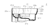
図9は、貯水槽2の一構成例を示す斜視図、図10は、貯水槽2の一構成例を示す平面図、図11は、図10のXI-XI線断面図である。貯水槽2は、上部が開口しており、空気を加湿するための水を貯留している。貯水槽2は、図5及び図10に示すように筐体1の内部に取り込まれる平面視矩形状の前部と、筐体1から後方へ突出する平面視半円弧状の後部とで構成されている。貯水槽2は斯かる平面形状を有する底部21と、該底部21の周縁を囲む貯水壁22とを有する。
図9は、貯水槽2の一構成例を示す斜視図、図10は、貯水槽2の一構成例を示す平面図、図11は、図10のXI-XI線断面図である。貯水槽2は、上部が開口しており、空気を加湿するための水を貯留している。貯水槽2は、図5及び図10に示すように筐体1の内部に取り込まれる平面視矩形状の前部と、筐体1から後方へ突出する平面視半円弧状の後部とで構成されている。貯水槽2は斯かる平面形状を有する底部21と、該底部21の周縁を囲む貯水壁22とを有する。
底部21は、後述の受水部21b及び通水溝21eが形成される平面視矩形状の底面21aを有する。底面21aは、後端部から前部の途中に亘って、横方向略中央部に形成されており、貯水壁22から適宜長離隔するような横幅を有している。底面21aの前方、即ち貯水槽2の前端部には略直方体の加湿フィルタ6の下部が嵌合する平面視矩形状のフィルタ嵌合凹部21f(貯水凹部)が形成されている。フィルタ嵌合凹部21fは、横方向両端に亘って形成されおり、底面21aよりも深く窪んでいる。なお、フィルタ嵌合凹部21fの形状は、必ずしも加湿フィルタ6の下部が嵌合する形状である必用は無く、少なくとも、加湿フィルタ6の下部を浸す水が溜まる凹形状であれば良い。また、貯水壁22の内側の全周に亘って底面21aよりも高い上段底面部21gが形成されている。上段底面部21gは、後述する覆体4を支持すると共に、加湿送風機が傾いた際に水が溢れにくくするための構造である。
貯水槽2の底面21aの後側部分には、給水タンク3から供給された水を受ける受水部21bが形成されている。給水タンク3は、図1及び図3に示すように平面視が貯水槽2と略同形の半円柱状をなすタンク本体31と、タンク本体31から下方へ突出した給水口32とを有する。給水口32はタンク本体31に螺合しており、給水口32を開閉させるための開閉棒33が進退可能に設けられている。開閉棒33は図示しない付勢手段によって閉方向に付勢されており、付勢力に抗して開閉棒33を押し込むことによって、給水口32が開口するように構成されている。受水部21bは、給水タンク3の給水口32の縁に倣って形成された円形の凹部である。つまり、受水部21bは、給水口32よりも一回り大きい円形の凹部である。受水部21bの中心は貯水槽2の横方向略中央部に位置しており、受水部21bの中央には、給水口32を開口させるための受水棒21cが上方へ突出している。貯水槽2の上部に給水タンク3が載置された場合、受水棒21cによって給水口32の開閉棒33が開方向へ押し込まれ、給水口32が開口する。
また、貯水槽2の底面21aには、受水部21bと、フィルタ嵌合凹部21fとを連通し、受水部21bで受けた水をフィルタ嵌合凹部21fへ流す通水溝21eが形成されている。より具体的には、通水溝21eは前後方向に長い直線状であり、貯水槽2の横方向略中央部に形成されている。また、通水溝21eは、受水部21b側よりもフィルタ嵌合凹部21f側の方が深くなるように傾斜している。
更に、受水部21bの周縁には、給水時に給水口32から前記給水タンク3へ空気を導入するための空気導入凹部21dが複数設けられている。例えば、図10に示すように3つの空気導入凹部21dと、通水溝21eとが受水部21bの周縁に等配されている。つまり、通水溝21eは受水部21bの前側に位置し、3つの空気導入凹部21dは受水部21bの横方向両側と、後側とに位置している。また、空気導入凹部21dは、受水部21bの中心より径方向外側の方が浅くなるように形成された傾斜底を有している。受水部21bの周方向及び径方向における空気導入凹部21dの幅は、通水溝21e部と同程度である。空気導入凹部21dの寸法は、加湿送風機が傾いた際にも、空気を給水タンク3内へ導入することが可能であれば特に限定されない。ただし、加湿送風機の転倒時に貯水槽2から溢れる水の量を減らすために、空気導入凹部21dは、空気導入可能な最小寸法で構成するのが望ましい。
また、貯水槽2の底面21aには、受水部21bと、フィルタ嵌合凹部21fとを連通し、受水部21bで受けた水をフィルタ嵌合凹部21fへ流す通水溝21eが形成されている。より具体的には、通水溝21eは前後方向に長い直線状であり、貯水槽2の横方向略中央部に形成されている。また、通水溝21eは、受水部21b側よりもフィルタ嵌合凹部21f側の方が深くなるように傾斜している。
更に、受水部21bの周縁には、給水時に給水口32から前記給水タンク3へ空気を導入するための空気導入凹部21dが複数設けられている。例えば、図10に示すように3つの空気導入凹部21dと、通水溝21eとが受水部21bの周縁に等配されている。つまり、通水溝21eは受水部21bの前側に位置し、3つの空気導入凹部21dは受水部21bの横方向両側と、後側とに位置している。また、空気導入凹部21dは、受水部21bの中心より径方向外側の方が浅くなるように形成された傾斜底を有している。受水部21bの周方向及び径方向における空気導入凹部21dの幅は、通水溝21e部と同程度である。空気導入凹部21dの寸法は、加湿送風機が傾いた際にも、空気を給水タンク3内へ導入することが可能であれば特に限定されない。ただし、加湿送風機の転倒時に貯水槽2から溢れる水の量を減らすために、空気導入凹部21dは、空気導入可能な最小寸法で構成するのが望ましい。
貯水壁22は、後部を構成する平面視円弧状の後面壁22aと、前部を構成する側壁22b、22cと、第1筐体部分11の隔壁11bに対向する対向壁22dとを有する。対向壁22dは、貯水槽2が隔壁11bの通流孔11c側へ傾いた際に、通流孔11cに対向していない対向壁22dの部位から、貯留された水を外部へ漏出させる漏出部を有する。具体的には、対向壁22dの上部に段状部分22fが形成されて前方へ迫り出しており、平面視において隔壁11bに対して斜めに対向する傾斜壁部22eが対向壁22dに設けられている。段状部分22fは、前方の方が後方に比べて高くなるように構成されている。傾斜壁部22eの横方向一端部は隔壁11bに当接している。該一端部は隔壁11bに当接して、貯水槽2のガタつきを抑えるための当接部として機能する。また、傾斜壁部22eの前記一端部には、加湿送風機が傾いた際、貯留された水を前記貯水槽2の外へ伝わせ、効果的に漏出させるための漏出凹部22gが形成されている。なお、貯水槽2の水を貯水槽2の外へ伝わせる構造は凹形状に限定されず、凸部であっても良い。
<覆体>
図12は、覆体4の一構成例を示した斜視図である。加湿送風機は、貯水槽2の開口を覆うと共に、加湿フィルタ6及び集塵フィルタ5を保持する覆体4を備える。覆体4は、貯水槽2の開口に倣って形成された覆板41を備える。具体的には、覆板41は、貯水槽2と同様、前部が平面視矩形状、後部が平面視半円弧状である。覆板41は周縁部から下方へ突出した周壁41aを備え、周壁41aが貯水槽2の上段底面部21gに支持されている。また、覆板41の周縁部には周壁41aよりも外側へ突出した鍔部41bが形成され、貯水槽2からの水の漏出を防止している。
図12は、覆体4の一構成例を示した斜視図である。加湿送風機は、貯水槽2の開口を覆うと共に、加湿フィルタ6及び集塵フィルタ5を保持する覆体4を備える。覆体4は、貯水槽2の開口に倣って形成された覆板41を備える。具体的には、覆板41は、貯水槽2と同様、前部が平面視矩形状、後部が平面視半円弧状である。覆板41は周縁部から下方へ突出した周壁41aを備え、周壁41aが貯水槽2の上段底面部21gに支持されている。また、覆板41の周縁部には周壁41aよりも外側へ突出した鍔部41bが形成され、貯水槽2からの水の漏出を防止している。
覆板41の後部には貯水タンクの給水口32が挿入される給水口挿入孔42が形成されている。また、覆板41の前部には加湿フィルタ6の下部が挿入されるフィルタ挿入孔43が形成されている。フィルタ挿入孔43は、平面視が横長長方形状であり、上方へ突出したリブ44が長辺の縁部分に形成されている。また、フィルタ挿入孔43の両短辺部分には、フィルタ挿入孔43に挿入された加湿フィルタ6を保持するフィルタ保持壁45が立設されている。各短辺部分に立設されたフィルタ保持壁45の上端部は横長の上板46によって接続されている。上板46の後側長辺の横方向略中央部には、集塵フィルタ5を固定するためのフィルタ係止突起46aが設けられている。また、フィルタ挿入孔43の後方の覆板41には、集塵フィルタ5固定用のフィルタ係止孔47が形成されている。更に、覆板41の前部と、後部との境界部分には、第2筐体部分12の筐体後面壁12dの下端部分を挾持する挾持部48が設けられている。
<集塵フィルタ>
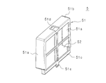
図13は、集塵フィルタ5の一構成例を示した斜視図、図14は、集塵フィルタ5の一構成例を示した正面図である。覆板41の上面側には集塵フィルタ5が配されている。集塵フィルタ5は、空気中の塵埃を捕捉するフィルタ部材52と、フィルタ部材52を保持すると共に、加湿フィルタ6の両側面及び上面側を囲む枠体51とを備える。枠体51は、フィルタ保持壁45を横方向外側から覆う枠体側面部51aと、上板46の上側を覆う枠体天面部51bと、枠体側面部51a及び枠体天面部51bの後側縁部に連続的に設けられた格子枠51cとで構成されている。格子枠51cにはフィルタ部材52が設けられ、加湿フィルタ6の後面側がフィルタ部材52によって覆われる。枠体天面部51bの横方向略中央部にはフィルタ係止突起46aが嵌合する係止突起嵌合孔51dが形成されている。また、格子枠51cの下部、横方向略中央部には、フィルタ係止孔47に係止されるフィルタ係止爪51eが設けられている。フィルタ保持壁45及び上板46に集塵フィルタ5を被せて、上板46のフィルタ係止突起46aを係止突起嵌合孔51dに嵌合させ、フィルタ係止爪51eをフィルタ係止孔47に挿入して係止させることによって、集塵フィルタ5を覆板41上に設置することができる。覆板41に立設された集塵フィルタ5の枠体側面部51a及び枠体天面部51bは筐体後面壁12dに当接し、格子枠51cの下辺も覆板41に当接しているため、塵埃が加湿フィルタ6を通じて、筐体1内部に流入することを防ぐことができる。
図13は、集塵フィルタ5の一構成例を示した斜視図、図14は、集塵フィルタ5の一構成例を示した正面図である。覆板41の上面側には集塵フィルタ5が配されている。集塵フィルタ5は、空気中の塵埃を捕捉するフィルタ部材52と、フィルタ部材52を保持すると共に、加湿フィルタ6の両側面及び上面側を囲む枠体51とを備える。枠体51は、フィルタ保持壁45を横方向外側から覆う枠体側面部51aと、上板46の上側を覆う枠体天面部51bと、枠体側面部51a及び枠体天面部51bの後側縁部に連続的に設けられた格子枠51cとで構成されている。格子枠51cにはフィルタ部材52が設けられ、加湿フィルタ6の後面側がフィルタ部材52によって覆われる。枠体天面部51bの横方向略中央部にはフィルタ係止突起46aが嵌合する係止突起嵌合孔51dが形成されている。また、格子枠51cの下部、横方向略中央部には、フィルタ係止孔47に係止されるフィルタ係止爪51eが設けられている。フィルタ保持壁45及び上板46に集塵フィルタ5を被せて、上板46のフィルタ係止突起46aを係止突起嵌合孔51dに嵌合させ、フィルタ係止爪51eをフィルタ係止孔47に挿入して係止させることによって、集塵フィルタ5を覆板41上に設置することができる。覆板41に立設された集塵フィルタ5の枠体側面部51a及び枠体天面部51bは筐体後面壁12dに当接し、格子枠51cの下辺も覆板41に当接しているため、塵埃が加湿フィルタ6を通じて、筐体1内部に流入することを防ぐことができる。
<帯電粒子発生ユニット>
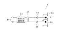
図15は、帯電粒子発生ユニット8の回路図である。帯電粒子発生ユニット8は、図示しない制御回路基板に接続するための接続端81を有する。帯電粒子発生ユニット8の接続端81は、接続端81に入力される直流電圧を交流電圧に変換する直流交流変換回路82に接続されている。直流交流変換回路82の出力端には高圧トランス83の一次コイルが接続され、交流電圧が一次コイルに印加されるように構成されている。高圧トランス83の二次コイルの一端には整流ダイオード84が順接続され、整流ダイオード84のカソードに正極針86が接続されている。高圧トランス83の二次コイルの他端には整流ダイオード85が逆接続され、整流ダイオード85のカソードに負極針87が接続されている。また帯電粒子発生ユニット8は、回路基板に接続することで接地される接地板88を有する。接地板88は適宜長離隔して形成された孔を有し、各孔の中心に正極針86及び負極針87の先端が位置するように、接地板88並びに正極針86及び負極針87が位置決め固定されている。
図15は、帯電粒子発生ユニット8の回路図である。帯電粒子発生ユニット8は、図示しない制御回路基板に接続するための接続端81を有する。帯電粒子発生ユニット8の接続端81は、接続端81に入力される直流電圧を交流電圧に変換する直流交流変換回路82に接続されている。直流交流変換回路82の出力端には高圧トランス83の一次コイルが接続され、交流電圧が一次コイルに印加されるように構成されている。高圧トランス83の二次コイルの一端には整流ダイオード84が順接続され、整流ダイオード84のカソードに正極針86が接続されている。高圧トランス83の二次コイルの他端には整流ダイオード85が逆接続され、整流ダイオード85のカソードに負極針87が接続されている。また帯電粒子発生ユニット8は、回路基板に接続することで接地される接地板88を有する。接地板88は適宜長離隔して形成された孔を有し、各孔の中心に正極針86及び負極針87の先端が位置するように、接地板88並びに正極針86及び負極針87が位置決め固定されている。
このように構成された加湿送風機によれば、集塵フィルタ5は筐体1内部に配されているため、集塵フィルタ5に溜まった塵埃が筐体1の外部から視認されることを防ぐことができる。
また、該塵埃が加湿送風機の外部に落下することを防ぐことができる。
また、該塵埃が加湿送風機の外部に落下することを防ぐことができる。
また、集塵フィルタ5は、貯水槽2の上部を覆う覆板41の上面側に立設されているため、集塵フィルタ5に溜まった塵埃が貯水槽2の水面に落下することを防止することができる。
更に、覆板41に形成されたフィルタ挿入孔43の縁にリブ44が設けられているため、覆板41上に付着した塵埃がフィルタ挿入孔43の方へ移動したとしても、塵埃はリブ44に捕捉される。従って、より効果的に塵埃が貯水槽2の水面に落下することを防止することができる。
更にまた、加湿フィルタ6は、集塵フィルタ5のフィルタ部材52及び枠体51によって、後面及び周縁全体を覆っているため、筐体1に吸い込まれた空気中の塵埃は加湿フィルタ6に到達する前に捕捉される。従って、空気中の塵埃が、加湿、送風、帯電粒子の発生が行われる構成部分に侵入することを効果的に防止することができる。
更にまた、吸込口12aは、第1筐体部分11と第2筐体部分12との接合部分に、上下に亘って形成された単一のスリット状であるため、複数の小スリット孔で構成されるスリット孔に比べて、空気の通流抵抗を小さくすることができ、小型の加湿送風機であっても効果的に空気を吸い込み、帯電粒子を含む加湿された空気を送風することができる。
更にまた、貯水槽2の底部21に受水部21b及び通水溝21eを設けることによって貯水槽2に貯留する水の量を抑えることができ、しかも加湿送風機の傾きに拘わらず、給水を円滑に行うことができる。
更にまた、受水部21bの周縁に空気導入凹部21dが設けられているため、加湿器が傾き、通水溝21e側からの空気の導入が困難になった場合であっても、空気導入凹部21dを通じて空気が給水口32から給水タンク3内に導入され、給水を円滑に行うことができる。
更にまた、受水部21bは円形であって、3つの空気導入凹部21dと、通水溝21eとが受水部21bの周縁に等配されているため、加湿器が前後左右方向のいずれの方向に傾斜しても空気導入凹部21d又は通水溝21eを通じて空気が給水口32から給水タンク3内に導入され、給水を円滑に行うことができる。
更にまた、空気導入凹部21dは、受水部21bの中心から離れる程、浅くなる傾斜底を有するため、空気導入凹部21dに溜まる水の量を抑えることができ、転倒時に溢れる水の量を少なくすることができる。
なお、本実施の形態では3つの空気導入凹部21dを設ける例を説明したが、空気導入凹部21dの数、配置、形状はこれに限定されるものではない。以下、空気導入凹部21dに係る変形例を説明する。
(変形例1)
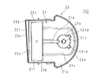
図16は変形例1に係る貯水槽102を示す平面図である。変形例1に係る貯水槽102は、実施の形態と同様、底部21及び貯水壁22を備え、底面21aには受水部21bが形成されている。受水部21bには、2つの空気導入凹部21dが、通水溝21eと共に3等配されている。つまり、受水部21bの周縁に、通水溝21eと、2つの空気導入凹部21dとが120度の間隔を空けて設けられている。
図16は変形例1に係る貯水槽102を示す平面図である。変形例1に係る貯水槽102は、実施の形態と同様、底部21及び貯水壁22を備え、底面21aには受水部21bが形成されている。受水部21bには、2つの空気導入凹部21dが、通水溝21eと共に3等配されている。つまり、受水部21bの周縁に、通水溝21eと、2つの空気導入凹部21dとが120度の間隔を空けて設けられている。
このように2つの空気導入凹部21dを設けた加湿送風機にあっては、加湿送風機が前後左右に傾いた場合であっても、通水溝21e、2つの空気導入凹部21dのいずれかから空気を導入することができ、より少数の空気導入凹部21dをもって、実施の形態と同様の効果を奏することができる。
(変形例2)
図17は変形例2に係る貯水槽202を示す平面図である。
変形例2に係る貯水槽202は、実施の形態と同様、底部21及び貯水壁22を備え、底面21aには受水部21bが形成されている。受水部21bには、円弧状の空気導入凹部21dが、通水溝21eと対向するように設けられている。受水部21bの後側の周縁に、円弧状の空気導入凹部21dが設けられている。空気導入凹部21dは、受水部21bを中心にして左右方向にそれぞれ略60度、全体で120度の範囲に亘って形成されている。
図17は変形例2に係る貯水槽202を示す平面図である。
変形例2に係る貯水槽202は、実施の形態と同様、底部21及び貯水壁22を備え、底面21aには受水部21bが形成されている。受水部21bには、円弧状の空気導入凹部21dが、通水溝21eと対向するように設けられている。受水部21bの後側の周縁に、円弧状の空気導入凹部21dが設けられている。空気導入凹部21dは、受水部21bを中心にして左右方向にそれぞれ略60度、全体で120度の範囲に亘って形成されている。
このように空気導入凹部21dを設けた加湿送風機にあっては、加湿送風機が前後左右に傾いた場合であっても、通水溝21e、2つの空気導入凹部21dのいずれかから空気を導入することができ、より効果的に空気を導入することができ、加湿フィルタ6への給水を円滑に行うことができる。
今回開示された実施の形態はすべての点で例示であって、制限的なものではないと考えられるべきである。本発明の範囲は、上記した意味ではなく、請求の範囲によって示され、請求の範囲と均等の意味及び範囲内でのすべての変更が含まれることが意図される。
1 筐体
2 貯水槽
3 給水タンク
4 覆体
5 集塵フィルタ
6 加湿フィルタ
7 送風機
8 帯電粒子発生ユニット
9 帯電粒子センサ
9a 正帯電粒子センサ部
10 通流路
11 第1筐体部分
11a 吹出口
11b 隔壁
11c 通流孔
11i 底板部
11j 貯水槽係止爪
12 第2筐体部分
12a 吸込口
13 分流板
21 底部
21a 底面
21b 受水部
21d 空気導入凹部
21e 通水溝
21f フィルタ嵌合凹部
21g 上段底面部
22 貯水壁
22d 対向壁
22e 傾斜壁部
22f 段状部分
22g 漏出凹部
31 タンク本体
32 給水口
41 覆板
42 給水口挿入孔
43 フィルタ挿入孔
44 リブ
51 枠体
52 フィルタ部材
86 正極針
87 負極針
91 抑制板
91a 上部抑制板
91b 下部抑制板
91c 切り欠き部
2 貯水槽
3 給水タンク
4 覆体
5 集塵フィルタ
6 加湿フィルタ
7 送風機
8 帯電粒子発生ユニット
9 帯電粒子センサ
9a 正帯電粒子センサ部
10 通流路
11 第1筐体部分
11a 吹出口
11b 隔壁
11c 通流孔
11i 底板部
11j 貯水槽係止爪
12 第2筐体部分
12a 吸込口
13 分流板
21 底部
21a 底面
21b 受水部
21d 空気導入凹部
21e 通水溝
21f フィルタ嵌合凹部
21g 上段底面部
22 貯水壁
22d 対向壁
22e 傾斜壁部
22f 段状部分
22g 漏出凹部
31 タンク本体
32 給水口
41 覆板
42 給水口挿入孔
43 フィルタ挿入孔
44 リブ
51 枠体
52 フィルタ部材
86 正極針
87 負極針
91 抑制板
91a 上部抑制板
91b 下部抑制板
91c 切り欠き部
Claims (10)
- 空気の吸込口、通流路及び吹出口を有する筐体と、空気を前記通流路に通流させる送風機と、上部が開口しており、空気を加湿するための水を貯留する貯水槽と、該貯水槽に一部が浸水し、他の一部が前記通流路に位置するように配された加湿フィルタと、該加湿フィルタよりも通流方向上流側に配され、空気中の塵埃を捕捉する集塵フィルタとを備える加湿器において、
前記加湿フィルタの前記一部が挿入される挿入孔を有し、前記貯水槽の開口を覆う覆板を備え、
前記集塵フィルタは前記覆板の上面側であって、前記筐体内の通流路の途中に配されている
ことを特徴とする加湿器。 - 前記挿入孔の縁に、上方へ突出したリブが形成されている
ことを特徴とする請求項1に記載の加湿器。 - 前記集塵フィルタは、
前記加湿フィルタに空気が流入する一の面に対向するフィルタ部材と、
前記覆板に立設されており、前記加湿フィルタに空気が流入する他の面を囲み、該フィルタ部材を保持する枠体と
を備えることを特徴とする請求項1又は請求項2に記載の加湿器。 - 前記筐体は、
前記通流路の下流側を構成する第1筐体部分と、
該第1筐体部分に接合し、前記通流路の上流側を構成する第2筐体部分と
を有し、
前記吸込口は、
前記第1筐体部分と、前記第2筐体部分との接合部分に形成されたスリット状をなす
ことを特徴とする請求項1から請求項3のいずれか一つに記載の加湿器。 - 前記通流路の途中に配され、帯電粒子を発生させる帯電粒子発生部を備え、
該帯電粒子発生部が発生させた帯電粒子を含む空気を前記吹出口から吹き出すようにしてある
ことを特徴とする請求項1から請求項4のいずれか一つに記載の加湿器。 - 空気の吸込口、通流路及び吹出口を有する筐体と、空気を前記通流路に通流させる送風機と、空気を加湿するための水を貯留する貯水槽と、該貯水槽の底部側へ突出した給水口を有し、該貯水槽に給水する給水タンクと、前記貯水槽に一部が浸水し、他の一部が前記通流路に位置するように配された加湿フィルタとを備える加湿器において、
前記貯水槽の底部は、
前記給水口の縁に倣って形成された凹状をなし、該給水口から供給された水を受ける受水部と、
前記加湿フィルタの前記一部を浸す水が溜まる貯水凹部と、
前記受水部及び前記貯水凹部を連通し、前記受水部で受けた水を前記貯水凹部へ流す通水溝と、
前記受水部の周縁に設けられており、給水時に前記給水口から前記給水タンクへ空気を導入するための空気導入凹部と
を備えることを特徴とする加湿器。 - 前記空気導入凹部及び前記通水溝の間に前記受水部が位置する
ことを特徴とする請求項6に記載の加湿器。 - 複数の前記空気導入凹部を有し、
前記受水部は円形であって、前記複数の空気導入凹部と、前記通水溝とが前記受水部の周縁に等配されている
ことを特徴とする請求項6又は請求項7に記載の加湿器。 - 前記空気導入凹部は、
前記受水部の中心側より、前記受水部から離隔した部位の方が浅い傾斜底を有する
ことを特徴とする請求項6から請求項8のいずれか一つに記載の加湿器。 - 前記通流路の途中に配され、帯電粒子を発生させる帯電粒子発生部を備え、
該帯電粒子発生部が発生させた帯電粒子を含む空気を前記吹出口から吹き出すようにしてある
ことを特徴とする請求項6から請求項9のいずれか一つに記載の加湿器。
Priority Applications (1)
| Application Number | Priority Date | Filing Date | Title |
|---|---|---|---|
| CN201390000720.7U CN204534941U (zh) | 2012-09-21 | 2013-09-12 | 加湿器 |
Applications Claiming Priority (4)
| Application Number | Priority Date | Filing Date | Title |
|---|---|---|---|
| JP2012-208388 | 2012-09-21 | ||
| JP2012-208390 | 2012-09-21 | ||
| JP2012208388A JP5991892B2 (ja) | 2012-09-21 | 2012-09-21 | 加湿器 |
| JP2012208390A JP5995625B2 (ja) | 2012-09-21 | 2012-09-21 | 加湿器 |
Publications (1)
| Publication Number | Publication Date |
|---|---|
| WO2014045991A1 true WO2014045991A1 (ja) | 2014-03-27 |
Family
ID=50341305
Family Applications (1)
| Application Number | Title | Priority Date | Filing Date |
|---|---|---|---|
| PCT/JP2013/074644 Ceased WO2014045991A1 (ja) | 2012-09-21 | 2013-09-12 | 加湿器 |
Country Status (2)
| Country | Link |
|---|---|
| CN (1) | CN204534941U (ja) |
| WO (1) | WO2014045991A1 (ja) |
Cited By (4)
| Publication number | Priority date | Publication date | Assignee | Title |
|---|---|---|---|---|
| EP3165841A4 (en) * | 2014-07-03 | 2017-06-28 | Qingdao Haier Air Conditioner Gen Corp., Ltd. | Humidification device and air treatment system |
| EP3165839A4 (en) * | 2014-07-03 | 2017-07-05 | Qingdao Haier Air Conditioner Gen Corp., Ltd. | Humidification device and air treatment system |
| CN109899895A (zh) * | 2019-02-22 | 2019-06-18 | 德业日本株式会社 | 新健康空气净化器的加湿器 |
| JP2021521407A (ja) * | 2018-09-10 | 2021-08-26 | 珠海格力電器股▲ふん▼有限公司Gree Electric Appliances, Inc. of Zhuhai | 加湿ファン |
Families Citing this family (3)
| Publication number | Priority date | Publication date | Assignee | Title |
|---|---|---|---|---|
| JP7002960B2 (ja) * | 2018-02-16 | 2022-01-20 | シャープ株式会社 | 加湿機 |
| JP7002959B2 (ja) * | 2018-02-16 | 2022-01-20 | シャープ株式会社 | 加湿機 |
| CN112513537B (zh) * | 2018-08-10 | 2022-03-04 | 夏普株式会社 | 加湿器 |
Citations (9)
| Publication number | Priority date | Publication date | Assignee | Title |
|---|---|---|---|---|
| JP2003214664A (ja) * | 2002-01-24 | 2003-07-30 | Honda Electronic Co Ltd | 超音波霧化装置 |
| JP2005055120A (ja) * | 2003-08-06 | 2005-03-03 | Sharp Corp | 加湿器 |
| JP2006046732A (ja) * | 2004-08-02 | 2006-02-16 | Sharp Corp | 加湿装置 |
| JP2007010230A (ja) * | 2005-06-30 | 2007-01-18 | Hitachi Appliances Inc | 空気清浄機 |
| JP2007276848A (ja) * | 2006-04-10 | 2007-10-25 | Zojirushi Corp | 液体貯留タンクの取付構造 |
| JP2007309610A (ja) * | 2006-05-19 | 2007-11-29 | Dainichi Co Ltd | 給液装置並びに給液装置を備えた加湿器及び給液装置を備えた暖房機 |
| JP2007322018A (ja) * | 2006-05-30 | 2007-12-13 | Sharp Corp | 加湿装置 |
| JP2010043845A (ja) * | 2008-07-14 | 2010-02-25 | Daikin Ind Ltd | 加湿装置 |
| JP2012013361A (ja) * | 2010-07-02 | 2012-01-19 | Panasonic Corp | 小型加湿機および静電霧化手段搭載の小型加湿機 |
-
2013
- 2013-09-12 WO PCT/JP2013/074644 patent/WO2014045991A1/ja not_active Ceased
- 2013-09-12 CN CN201390000720.7U patent/CN204534941U/zh not_active Expired - Lifetime
Patent Citations (9)
| Publication number | Priority date | Publication date | Assignee | Title |
|---|---|---|---|---|
| JP2003214664A (ja) * | 2002-01-24 | 2003-07-30 | Honda Electronic Co Ltd | 超音波霧化装置 |
| JP2005055120A (ja) * | 2003-08-06 | 2005-03-03 | Sharp Corp | 加湿器 |
| JP2006046732A (ja) * | 2004-08-02 | 2006-02-16 | Sharp Corp | 加湿装置 |
| JP2007010230A (ja) * | 2005-06-30 | 2007-01-18 | Hitachi Appliances Inc | 空気清浄機 |
| JP2007276848A (ja) * | 2006-04-10 | 2007-10-25 | Zojirushi Corp | 液体貯留タンクの取付構造 |
| JP2007309610A (ja) * | 2006-05-19 | 2007-11-29 | Dainichi Co Ltd | 給液装置並びに給液装置を備えた加湿器及び給液装置を備えた暖房機 |
| JP2007322018A (ja) * | 2006-05-30 | 2007-12-13 | Sharp Corp | 加湿装置 |
| JP2010043845A (ja) * | 2008-07-14 | 2010-02-25 | Daikin Ind Ltd | 加湿装置 |
| JP2012013361A (ja) * | 2010-07-02 | 2012-01-19 | Panasonic Corp | 小型加湿機および静電霧化手段搭載の小型加湿機 |
Cited By (6)
| Publication number | Priority date | Publication date | Assignee | Title |
|---|---|---|---|---|
| EP3165841A4 (en) * | 2014-07-03 | 2017-06-28 | Qingdao Haier Air Conditioner Gen Corp., Ltd. | Humidification device and air treatment system |
| EP3165839A4 (en) * | 2014-07-03 | 2017-07-05 | Qingdao Haier Air Conditioner Gen Corp., Ltd. | Humidification device and air treatment system |
| US10415839B2 (en) | 2014-07-03 | 2019-09-17 | Qingdao Haier Air Conditioner General Corp., Ltd. | Humidification device and air treatment system |
| JP2021521407A (ja) * | 2018-09-10 | 2021-08-26 | 珠海格力電器股▲ふん▼有限公司Gree Electric Appliances, Inc. of Zhuhai | 加湿ファン |
| JP7123172B2 (ja) | 2018-09-10 | 2022-08-22 | 珠海格力電器股▲ふん▼有限公司 | 加湿ファン |
| CN109899895A (zh) * | 2019-02-22 | 2019-06-18 | 德业日本株式会社 | 新健康空气净化器的加湿器 |
Also Published As
| Publication number | Publication date |
|---|---|
| CN204534941U (zh) | 2015-08-05 |
Similar Documents
| Publication | Publication Date | Title |
|---|---|---|
| WO2014045991A1 (ja) | 加湿器 | |
| JP5370290B2 (ja) | 小型加湿機および静電霧化手段搭載の小型加湿機 | |
| US12478107B2 (en) | Vaporization top base, vaporizer, and electronic vaporization device | |
| CN111033131B (zh) | 送风装置 | |
| JP6979567B2 (ja) | 加湿装置 | |
| JP5930929B2 (ja) | 加湿器 | |
| JP2010007885A (ja) | 加湿板、加湿装置および加湿機能付き空気清浄機 | |
| JP5995625B2 (ja) | 加湿器 | |
| JP5991892B2 (ja) | 加湿器 | |
| JP6000039B2 (ja) | 送風機器 | |
| JP6050502B2 (ja) | イオン発生装置および空気調和機 | |
| JP5980069B2 (ja) | 加湿器 | |
| JP4630245B2 (ja) | 加湿装置 | |
| JP2010096477A (ja) | 加湿装置および加湿機能付き空気清浄機 | |
| JP5930923B2 (ja) | 送風装置用のスタンド | |
| CN110999002B (zh) | 放电装置 | |
| CN102410599A (zh) | 加湿器 | |
| JP2010007884A (ja) | 加湿装置および加湿機能付き空気清浄機 | |
| KR20170024475A (ko) | 가습공기청정기 | |
| WO2015025541A1 (ja) | 空気調和機およびイオン発生装置 | |
| JP5348086B2 (ja) | 小型加湿機および静電霧化手段搭載の小型加湿機 | |
| JP5434834B2 (ja) | 小型加湿機 | |
| JP2010060155A (ja) | 加湿装置および加湿機能付き空気清浄機 | |
| JP2024175381A (ja) | 加湿装置 | |
| JP2024175388A (ja) | 加湿装置 |
Legal Events
| Date | Code | Title | Description |
|---|---|---|---|
| WWE | Wipo information: entry into national phase |
Ref document number: 201390000720.7 Country of ref document: CN |
|
| 121 | Ep: the epo has been informed by wipo that ep was designated in this application |
Ref document number: 13838259 Country of ref document: EP Kind code of ref document: A1 |
|
| NENP | Non-entry into the national phase |
Ref country code: DE |
|
| 122 | Ep: pct application non-entry in european phase |
Ref document number: 13838259 Country of ref document: EP Kind code of ref document: A1 |