WO2014041916A1 - カーテンシールドエアバッグ装置の設置構造 - Google Patents
カーテンシールドエアバッグ装置の設置構造 Download PDFInfo
- Publication number
- WO2014041916A1 WO2014041916A1 PCT/JP2013/070886 JP2013070886W WO2014041916A1 WO 2014041916 A1 WO2014041916 A1 WO 2014041916A1 JP 2013070886 W JP2013070886 W JP 2013070886W WO 2014041916 A1 WO2014041916 A1 WO 2014041916A1
- Authority
- WO
- WIPO (PCT)
- Prior art keywords
- bag body
- hook
- airbag device
- support bracket
- curtain shield
- Prior art date
- Legal status (The legal status is an assumption and is not a legal conclusion. Google has not performed a legal analysis and makes no representation as to the accuracy of the status listed.)
- Ceased
Links
Images



Classifications
-
- B—PERFORMING OPERATIONS; TRANSPORTING
- B60—VEHICLES IN GENERAL
- B60R—VEHICLES, VEHICLE FITTINGS, OR VEHICLE PARTS, NOT OTHERWISE PROVIDED FOR
- B60R21/00—Arrangements or fittings on vehicles for protecting or preventing injuries to occupants or pedestrians in case of accidents or other traffic risks
- B60R21/02—Occupant safety arrangements or fittings, e.g. crash pads
- B60R21/16—Inflatable occupant restraints or confinements designed to inflate upon impact or impending impact, e.g. air bags
- B60R21/20—Arrangements for storing inflatable members in their non-use or deflated condition; Arrangement or mounting of air bag modules or components
- B60R21/213—Arrangements for storing inflatable members in their non-use or deflated condition; Arrangement or mounting of air bag modules or components in vehicle roof frames or pillars
Definitions
- the present invention relates to an installation structure of a curtain shield airbag device installed in a vehicle.
- airbags are known as one of the occupant protection systems for automobiles.
- Such an airbag includes what is called a curtain shield airbag device.
- the curtain shield airbag device is inflated from a portion along the roof side rail at the time of an automobile side collision or an automobile rollover, and protects the head and neck of the driver's seat passenger, the passenger on the passenger seat, and the passenger on the rear seat.
- This curtain shield airbag device also includes a bag body and an inflator, like a general airbag.
- the bag body is formed in a bag shape, and the inflator generates an inflation fluid that flows into the bag body.
- This type of curtain shield airbag device is installed on the body frame according to the following procedure.
- a ceiling module vehicle ceiling
- a sun visor, an interior molding mall, an assist grip, and the like are assembled.
- the curtain shield airbag device is fixed to the pillar (see, for example, Japanese Patent Laid-Open Nos. 2000-198407 and 2009-67221). That is, the bag constituting the curtain shield airbag device is screwed to the pillar.
- the inflated and unfolded bag body hangs down from the roof side rail.
- the bag body that hangs down in this manner is supported by pillars of the vehicle body frame that are screw-fixed. Conventionally, in order to sufficiently support the bag body that hangs down in this manner, it has been considered that the bag body is screwed to the bracket of the assist grip.
- an installation structure for a curtain shield airbag device installed in a vehicle such as an automobile is provided.
- the curtain shield airbag device includes a bag body that is formed in a bag shape and into which inflation fluid flows and an inflator that generates inflation fluid that flows into the bag body.
- a ring-shaped hook portion formed so that the protruding shape of the grip support bracket fixed to the vehicle body frame can be inserted is provided on the upper portion of the bag body when inflated and deployed.
- the bag body is configured to be able to be suspended from the grip support bracket by hooking the hook portion through the protruding shape of the grip support bracket.
- the upper portion of the bag body when inflated and deployed has a hook portion, and the bag body can be suspended from the grip support bracket by hooking the hook portion.
- the bag body can be suspended and supported by the grip support bracket by the hooking portion. Therefore, the screw fixing member used for screw fixing the bag body can be eliminated, the number of parts can be reduced, and the installation cost of the curtain shield airbag device can be reduced. Further, the screw fixing work for fixing the bag body to the screw can be reduced, and the installation work can be simplified.
- the curtain shield airbag device is incorporated into the ceiling module body as part of a ceiling module assembled to the vehicle body frame.
- the curtain shield airbag device can be positioned and arranged with respect to the vehicle body frame at the same time that the ceiling module is assembled to the vehicle body frame. Therefore, in installing the curtain shield airbag device, installation work such as positioning work can be omitted, and the installation work can be simplified.
- a curtain shield airbag device includes a protector that receives support from the grip support bracket, and the protector is configured to inflate and deploy the bag body that is generated when the bag body is inflated and deployed. Support reaction force. According to the installation structure of the curtain shield airbag device, the bag body is inflated and deployed by the protector, and can be guided more accurately so that the bag body is in a predetermined inflated and deployed state.
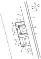
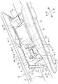
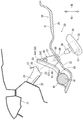
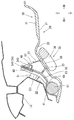
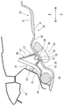
- FIG. 2 is an enlarged view of a rounded portion II in FIG. 1. It is a disassembled perspective view of a ceiling module. It is an enlarged view of the hook part of FIG. It is a perspective view which shows the assembly
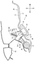
- FIG. 7 is a sectional view taken along line VII-VII in FIG. 5.
- FIG. 6 is a sectional view taken along line VIII-VIII in FIG. 5.
- FIG. 6 is a sectional view taken along line IX-IX in FIG. 5.
- the ceiling module 30 forms the ceiling of an automobile as a vehicle.
- the vehicle in which the ceiling module 30 is disposed is a type of vehicle in which seats are provided in three rows in the front and rear. For this reason, the ceiling module 30 is provided with a sunroof structure or the like.
- the ceiling module 30 is assembled to the vehicle body frame 10 so as to form the ceiling of the vehicle.
- the ceiling module 30 generally includes a ceiling module body 31 and a curtain airbag 40.
- a curtain airbag 40 is assembled to the side portion of the ceiling module body 31.
- the curtain airbag 40 is incorporated in the ceiling module main body 31 as a part of the ceiling module 30 assembled to the vehicle body frame 10.
- the ceiling module body 31 is configured as a conventional ceiling module, and the molded ceiling 32 is equipped with module parts (not shown, for example, an overhead console, a room lamp, etc.).
- a sun visor not shown
- an interior molding not shown
- an assist grip 35 and the like are assembled.
- a vehicle body frame 10 shown in FIG. 3 or the like constitutes a framework of an automobile and includes a front pillar 11, an A pillar 12, a B pillar 13, and a C pillar 14 in order from the front.
- a roof side rail 15 integrated so as to connect the upper ends of the pillars 11, 12, 13, 14 is provided.
- the ceiling module 30 is assembled along the roof side rail 15.
- the roof side rail 15 is provided with a grip support bracket 20 according to the location where the assist grip 35 is disposed. Specifically, as shown in FIG. 3, three assist grips 35 are disposed on one side of the roof side rail 15. Two grip support brackets 20 are provided in parallel with the roof side rail 15 so as to support the assist grip 35 at two points. In this way, the grip support brackets 20 provided on the roof side rail 15 are provided at six locations that make a pair according to the number of the three assist grips 35.
- the grip support bracket 20 includes a leg portion 21, a holding portion 23, a locking hole 25, and an engagement support portion 27.
- the end portions 22 and 22 on one side of the leg portions 21 and 21 are spot welded to the roof side rail 15, and the other side extends so as to protrude toward the vehicle interior.
- the holding portion 23 is provided with a locking hole 25 for locking the locking convex portion 38 of the assist grip 35.
- an engagement support portion 27 having a return shape for retaining is provided above the locking hole 25.
- the grip support bracket 20 has a protruding shape that can be inserted into the hook portion 62 of the curtain airbag 40 described later at the leg portion 21.
- the protruding shape of the legs 21 and 21 ensures a structure for hooking a hook 62 described later.
- the curtain airbag 40 as a curtain shield airbag device according to the present invention will be described.
- the curtain airbag 40 generally includes a protector 41, a bag body 61, and an inflator 65 (see FIG. 3).
- the bag body 61 is formed in a bag shape so that the inflation fluid flows into the bag body 61.
- the illustrated bag body 61 is in a wound state before being expanded and deployed.
- the inflator 65 generates an inflation fluid that flows into the bag body 61.
- the protector 41 includes a holding part 42, a screw fixing part 45, and a hook support part 51 as functions.
- the holding part 42 includes a bag holding part 421 that holds the bag body 61 and an inflator holding part 422 that holds the inflator 65.
- the bag holding portion 421 and the inflator holding portion 422 are provided with screw fixing portions 45 having appropriate screw holes.
- the A screw fixing portion 451 is screwed to the A pillar 12 and the B screw fixing portion 452 is screwed to the B pillar 13.
- a C screw fixing portion 453 is screwed to the C pillar 14.
- the protector 41 having the holding portion 42 and the screw fixing portion 45 holds the bag member 61 and the inflator 65 with respect to the A pillar 12, the B pillar 13, and the C pillar 14.
- the screw is fixed via the figure.
- the protector 41 is provided with a hook support portion 51.
- the hook support portion 51 is formed so as to protrude above the protector 41 described above.
- the hook support portion 51 is provided with a hook holding portion 52 and an assembly portion 57 on each of the front and rear sides.
- the hook holding portion 52 and the assembly portion 57 are provided on a common resin plate member 53.
- Bending portions 531 and 532 are provided at the front and rear edges of the plate member 53. Further, support protruding pieces 533 and 534 that abut against the ceiling module main body 31 are provided at portions adjacent to the bent portions 531 and 532.
- the hook holding portion 52 holds a hook portion 62 that is integrally attached to the bag body 61.
- the hook holding portion 52 generally includes a grip portion 54 and a communication hole 55.
- the grip portion 54 is configured to grip the upper end edge of the hook portion 62.
- the grip portion 54 includes a hinge portion 541, a sandwiching plate portion 542, and a locking portion 543. That is, the sandwiching plate portion 542 is folded back by the hinge portion 541 to sandwich the hook portion 62 with the plate-like member 53.
- the locking part 543 is provided on the opposite side of the hinge part 541 in the sandwiching plate part 542. The locking portion 543 is locked by having a structure that fits with the plate-like member 53.
- the sandwiching plate portion 542 sandwiching the hooking portion 62 in this manner holds the hooking portion 62 between the sandwiching plate portion 542 and the plate-like member 53 by locking the locking portion 543.
- the communication hole 55 provided in the hook holding portion 52 has a hole shape communicating with the hook hole 63 provided in the hook portion 62.
- the grip support bracket 20 is inserted into the communication hole 55 like the hooking hole 63 of the hooking portion 62.
- the plate-like member 53 that sandwiches the hook portion 62 with the pinch plate portion 542 guides and holds the hole position of the hook hole 63 of the hook portion 62 with the guide rib 535.
- the protector 41 including the plate-like member 53 sandwiched in this way receives a support force from the grip support bracket 20 inserted into the communication hole 55.
- the protector 41 grips the hook portion 62 integrated with the bag body 61 by the grip portion 54.
- the protector 41 can receive the reaction force of the expansion and expansion of the bag body 61 when the bag body 61 is expanded and deployed. That is, the protector 41 supports the reaction force of the expansion and expansion of the bag body 61 that occurs when the bag body 61 is expanded and deployed.
- the engagement support portion 27 of the grip support bracket 20 inserted into the communication hole 55 is locked to the upper part of the periphery of the communication hole 55.
- the grip support bracket 20 inserted into the communication hole 55 supports the hook support portion 51 that holds the hook portion 62. That is, the grip support bracket 20 supports the curtain airbag 40 including the protector 41 (the hook support portion 51).
- the assembly portion 57 is provided on the plate-like member 53 that forms the above-described hook holding portion 52.
- the assembly portion 57 has a shape protruding toward the vehicle interior so as to be able to come into contact with the ceiling module body 31.
- the assembly portion 57 is provided with an engagement hole 58 with which the flange member 59 is engaged.
- the flange member 59 is engaged with the engagement hole 58 in a state where the molded ceiling 32 of the ceiling module body 31 is sandwiched between the assembly portions 57.
- the hooking support portion 51 is integrally fastened to the ceiling module main body 31 by the assembling portion 57.
- the ceiling module body 31 is provided with an appropriate insertion hole through which the flange member 59 is inserted.
- attachment part 57 is arrange
- a ring-shaped hook 62 is provided on the upper portion of the bag body 61.
- the hook portion 62 is provided by being sewn to the upper portion of the bag body 61 when inflated and deployed. That is, the hook 62 is also provided on the upper portion of the bag body 61 in the wound state of the bag body 61 before being inflated and deployed in a shape simulating the handle of the bag.
- the hook portion 62 is formed by overlapping and sewing several cloth-like materials of the bag body 61 (about three).
- the hook portion 62 is formed in a ring shape to form a hook hole 63 that is formed so that the protruding shape of the grip support bracket 20 can be inserted with play.
- the size of the hooking hole 63 is such that the protruding shape of the grip support bracket 20 and the hooking hole 63 are inserted when the protruding shape of the grip support bracket 20 is inserted. Is set to a size that allows play.
- the opening shape of the hooking hole 63 is formed to have a rectangular shape corresponding to the protruding shape of the grip support bracket 20.
- the outer peripheral edge of the hooking portion 62 forming the hooking hole 63 is also formed to have a rectangular shape.
- the bag body 61 is suspended from the grip support bracket 20.
- the grip support bracket 20 is also inserted into the communication hole 55 of the hook holding portion 52 that holds the hook portion 62, the hook holding portion 52 is also hooked by the grip support bracket 20.
- the part located in the lower part of the inner periphery of the hook 62 in the bag body 61 is set as a bulging part 64.
- the bulging portion 64 expands with the expansion of the bag body 61 when the inflation fluid flows from the inflator 65 and the bag body 61 expands and deploys.
- the portion where the bulging portion 64 is set is a portion set on the upper portion of the bag body 61 where the hooking hole 63 is set, and is configured as the inner periphery of the hooking portion 62 of the bag body 61 described above. It is a part to be done.
- the bulging portion 64 swells due to the inflow of the inflation fluid from the inflator 65, as with the normal bag body 61.
- the expanded bulging portion 64 abuts against the leg portion 21 of the grip support bracket 20 as described above. Then, the bulging portion 64 can receive a support force from the grip support bracket 20. That is, the bulging portion 64 that receives the support force from the grip support bracket 20 in this way can support the expansion and deployment of the bag body 61 other than the bulging portion 64.
- the above-described hook portion 62 is formed by stitching a plurality of cloth-like materials different from the bag body 61.
- the hook portion 62 may be constituted by a part of the bag body 61. That is, the hook portion 62 may be configured so that the bag body 61 communicates with the inside thereof.
- the hook portion 62 may be formed in a bag shape as a part of the bag body 61 communicating with the inside of the bag body 61.
- the hook 62 is disposed closer to the inflator 65 than the bag body 61. For this reason, the inflating fluid from the inflator 65 flows into the hook portion 62 before flowing into the bag body 61, and the hook portion 62 inflates and expands earlier than the bag body 61. Thus, the hook 62 is inflated and deployed first.
- the hook 62 is in close contact with the grip support bracket 20 and receives support from the grip support bracket 20. As a result, the hook 62 can guide the subsequent expansion and expansion of the bag body 61 while receiving support from the grip support bracket 20.
- the ceiling module 30 with the curtain airbag 40 assembled as described above has the assist support in a state where the grip support bracket 20 is inserted through the hooking hole 63 and the communication hole 55 as described above.
- a grip 35 is installed.
- the assist grip 35 generally includes a grip body 36, a rotation shaft 37, and a locking projection 38.
- the grip body 36 is formed to have a shape that can be gripped.
- a pivot shaft 37 is supported on the grip body 36.
- a locking projection 38 is rotatably supported on the rotation shaft 37. For this reason, the locking projection 38 is rotatable relative to the grip body 36.
- the locking projection 38 has a shape that fits in a hole shape so as to be prevented from coming off.
- the ceiling module body 31 is provided with an appropriate insertion hole through which the locking convex portion 38 of the assist bracket 35 is inserted, similarly to the above-described flange member 59.
- the locking projection 38 of the assist grip 35 is locked to the locking hole 25 of the grip support bracket 20.
- the assist grip 35 is engaged with the engagement hole 25 of the grip support bracket 20 with the molded ceiling 32 of the ceiling module body 31 sandwiched therebetween, whereby the ceiling module body 31 is secured to the vehicle body frame 10.
- the hook holding portion 52 of the curtain airbag 40 assembled to the ceiling module body is supported by the grip support bracket 20.
- the hook portion 62 held by the hook holding portion 52 is also supported by the grip support bracket 20.
- the hook portion 62 is provided on the upper portion of the bag body 61 when the curtain airbag 40 is inflated and deployed. 20 can be suspended. Accordingly, the bag body 61 can be suspended and supported on the grip support bracket 20 by the hooking portion 62 being hooked. Therefore, the screw fixing member used for screw fixing the bag body 61 can be eliminated, the number of parts can be reduced, and the installation cost of the curtain airbag 40 can be reduced. Further, the screw fixing work for fixing the bag body 61 with screws can be reduced, and the installation work can be simplified.
- the bulging portion 64 comes into close contact with the grip support bracket 20 due to inflation and receives support force from the grip support bracket 20 so that the bag body 61 other than the bulging portion 64 can Supports inflated deployment.
- the support force from the bulging portion 64 is received, and the bag body 61 is guided so as to be inflated and deployed in a predetermined manner. Therefore, the inflation and deployment of the bag body 61 can be a more stable predetermined inflation and deployment.
- the curtain airbag 40 is incorporated into the ceiling module body 31 as a part of the ceiling module 30 assembled to the vehicle body frame 10.
- the curtain airbag 40 can be positioned and disposed with respect to the vehicle body frame 10 at the same time that the ceiling module 30 is assembled to the vehicle body frame 10. Therefore, when installing the curtain airbag 40, installation work such as positioning work can be omitted, and the installation work can be simplified.
- the protector 41 that receives the support from the grip support bracket 20 supports the reaction force of the expansion and deployment of the bag body 61 that occurs when the bag body 61 is inflated and deployed. . Accordingly, the bag body 61 can be inflated and deployed by the protector 41, and can be more accurately guided so that the bag body 61 is in a predetermined inflated and deployed state.
- the portion of the bag body 61 located at the lower portion of the inner periphery of the hooking portion 62 is set as the bulging portion 64, but the bulging portion according to the present invention is Without being limited, it is only necessary that at least a part of the inner periphery of the hook portion is set so that the inflation fluid first flows in the bag body inflated and deployed by the inflow of the inflation fluid.
- the protector 41 described above may be configured to include an appropriate configuration that supports the reaction force of the expansion and expansion of the bag body 61 that occurs when the bag body 61 is inflated and deployed.
Landscapes
- Engineering & Computer Science (AREA)
- Mechanical Engineering (AREA)
- Air Bags (AREA)
Applications Claiming Priority (2)
| Application Number | Priority Date | Filing Date | Title |
|---|---|---|---|
| JP2012199417A JP5962360B2 (ja) | 2012-09-11 | 2012-09-11 | カーテンシールドエアバッグ装置の設置構造 |
| JP2012-199417 | 2012-09-11 |
Publications (1)
| Publication Number | Publication Date |
|---|---|
| WO2014041916A1 true WO2014041916A1 (ja) | 2014-03-20 |
Family
ID=50278044
Family Applications (1)
| Application Number | Title | Priority Date | Filing Date |
|---|---|---|---|
| PCT/JP2013/070886 Ceased WO2014041916A1 (ja) | 2012-09-11 | 2013-08-01 | カーテンシールドエアバッグ装置の設置構造 |
Country Status (2)
| Country | Link |
|---|---|
| JP (1) | JP5962360B2 (cg-RX-API-DMAC7.html) |
| WO (1) | WO2014041916A1 (cg-RX-API-DMAC7.html) |
Families Citing this family (1)
| Publication number | Priority date | Publication date | Assignee | Title |
|---|---|---|---|---|
| US9896054B2 (en) * | 2016-01-28 | 2018-02-20 | Toyota Motor Engineering & Manufacturing North America, Inc. | Dual purpose temporary clip for vehicle |
Citations (3)
| Publication number | Priority date | Publication date | Assignee | Title |
|---|---|---|---|---|
| JP2011068276A (ja) * | 2009-09-25 | 2011-04-07 | Autoliv Development Ab | カーテンエアバッグ装置 |
| JP2012153325A (ja) * | 2011-01-28 | 2012-08-16 | Autoliv Development Ab | カバー |
| JP2012162153A (ja) * | 2011-02-04 | 2012-08-30 | Toyota Motor Corp | 天井モジュール及びこれを備えた車両 |
Family Cites Families (3)
| Publication number | Priority date | Publication date | Assignee | Title |
|---|---|---|---|---|
| JP3261048B2 (ja) * | 1996-11-07 | 2002-02-25 | トヨタ自動車株式会社 | 自動車用乗員保護装置の固定構造 |
| JP4609998B2 (ja) * | 2005-02-04 | 2011-01-12 | 日本プラスト株式会社 | エアバッグ装置 |
| EP2543558B1 (en) * | 2010-03-04 | 2014-09-03 | Toyota Jidosha Kabushiki Kaisha | Arrangement structure for curtain airbag device |
-
2012
- 2012-09-11 JP JP2012199417A patent/JP5962360B2/ja active Active
-
2013
- 2013-08-01 WO PCT/JP2013/070886 patent/WO2014041916A1/ja not_active Ceased
Patent Citations (3)
| Publication number | Priority date | Publication date | Assignee | Title |
|---|---|---|---|---|
| JP2011068276A (ja) * | 2009-09-25 | 2011-04-07 | Autoliv Development Ab | カーテンエアバッグ装置 |
| JP2012153325A (ja) * | 2011-01-28 | 2012-08-16 | Autoliv Development Ab | カバー |
| JP2012162153A (ja) * | 2011-02-04 | 2012-08-30 | Toyota Motor Corp | 天井モジュール及びこれを備えた車両 |
Also Published As
| Publication number | Publication date |
|---|---|
| JP2014054867A (ja) | 2014-03-27 |
| JP5962360B2 (ja) | 2016-08-03 |
Similar Documents
| Publication | Publication Date | Title |
|---|---|---|
| JP4434193B2 (ja) | 車両用サイドエアバッグ装置 | |
| US7971900B2 (en) | Side airbag apparatus for vehicles | |
| US7185912B2 (en) | Knee protection airbag device | |
| JP5001293B2 (ja) | エアバッグ・モジュール用の可撓ハウジング | |
| JP5969792B2 (ja) | 頭部保護エアバッグの組付方法 | |
| JP4281644B2 (ja) | インフレーター | |
| JP2010535130A (ja) | 助手席エアバッグ搭載装置 | |
| KR102227852B1 (ko) | 커튼 에어백 장치 및 그것의 제조방법 | |
| JP2016022918A (ja) | カーテンエアバッグ装置及びカーテンエアバッグの折り畳み方法 | |
| JP5849910B2 (ja) | カーテンシールドエアバッグ装置 | |
| JP5988611B2 (ja) | エアバッグ装置 | |
| JP5962360B2 (ja) | カーテンシールドエアバッグ装置の設置構造 | |
| JP5550315B2 (ja) | エアバッグ装置 | |
| JP2010052513A (ja) | エアバッグ及びエアバッグ装置 | |
| JP4841164B2 (ja) | エアバッグ装置 | |
| JPH03227753A (ja) | 自動車のエアバック装置 | |
| JP5973815B2 (ja) | 車両用カーテンエアバッグ及び車両用カーテンエアバッグの車両搭載構造 | |
| JP2018076026A (ja) | カーテンエアバッグ | |
| JP2012020674A (ja) | 車両用カーテンエアバッグ装置 | |
| JP2002337652A (ja) | 膝保護用エアバッグ装置 | |
| JP2009234360A (ja) | エアバッグ装置 | |
| JP2003048503A (ja) | 頭部保護エアバッグ装置 | |
| JP6996270B2 (ja) | カーテンエアバッグ装置の搭載構造 | |
| JP6489040B2 (ja) | 頭部保護エアバッグ装置 | |
| JP2009226994A (ja) | カーテンエアバッグモジュール |
Legal Events
| Date | Code | Title | Description |
|---|---|---|---|
| 121 | Ep: the epo has been informed by wipo that ep was designated in this application |
Ref document number: 13836552 Country of ref document: EP Kind code of ref document: A1 |
|
| WWE | Wipo information: entry into national phase |
Ref document number: IDP00201500966 Country of ref document: ID |
|
| NENP | Non-entry into the national phase |
Ref country code: DE |
|
| 122 | Ep: pct application non-entry in european phase |
Ref document number: 13836552 Country of ref document: EP Kind code of ref document: A1 |