WO2014038543A1 - コネクタ - Google Patents
コネクタ Download PDFInfo
- Publication number
- WO2014038543A1 WO2014038543A1 PCT/JP2013/073668 JP2013073668W WO2014038543A1 WO 2014038543 A1 WO2014038543 A1 WO 2014038543A1 JP 2013073668 W JP2013073668 W JP 2013073668W WO 2014038543 A1 WO2014038543 A1 WO 2014038543A1
- Authority
- WO
- WIPO (PCT)
- Prior art keywords
- connector
- female
- male connector
- male
- protrusion
- Prior art date
- Legal status (The legal status is an assumption and is not a legal conclusion. Google has not performed a legal analysis and makes no representation as to the accuracy of the status listed.)
- Ceased
Links
Images



Classifications
-
- H—ELECTRICITY
- H01—ELECTRIC ELEMENTS
- H01R—ELECTRICALLY-CONDUCTIVE CONNECTIONS; STRUCTURAL ASSOCIATIONS OF A PLURALITY OF MUTUALLY-INSULATED ELECTRICAL CONNECTING ELEMENTS; COUPLING DEVICES; CURRENT COLLECTORS
- H01R13/00—Details of coupling devices of the kinds covered by groups H01R12/70 or H01R24/00 - H01R33/00
- H01R13/46—Bases; Cases
- H01R13/502—Bases; Cases composed of different pieces
-
- H—ELECTRICITY
- H01—ELECTRIC ELEMENTS
- H01R—ELECTRICALLY-CONDUCTIVE CONNECTIONS; STRUCTURAL ASSOCIATIONS OF A PLURALITY OF MUTUALLY-INSULATED ELECTRICAL CONNECTING ELEMENTS; COUPLING DEVICES; CURRENT COLLECTORS
- H01R13/00—Details of coupling devices of the kinds covered by groups H01R12/70 or H01R24/00 - H01R33/00
- H01R13/46—Bases; Cases
- H01R13/502—Bases; Cases composed of different pieces
- H01R13/506—Bases; Cases composed of different pieces assembled by snap action of the parts
-
- H—ELECTRICITY
- H01—ELECTRIC ELEMENTS
- H01R—ELECTRICALLY-CONDUCTIVE CONNECTIONS; STRUCTURAL ASSOCIATIONS OF A PLURALITY OF MUTUALLY-INSULATED ELECTRICAL CONNECTING ELEMENTS; COUPLING DEVICES; CURRENT COLLECTORS
- H01R13/00—Details of coupling devices of the kinds covered by groups H01R12/70 or H01R24/00 - H01R33/00
- H01R13/46—Bases; Cases
- H01R13/533—Bases, cases made for use in extreme conditions, e.g. high temperature, radiation, vibration, corrosive environment, pressure
-
- H—ELECTRICITY
- H01—ELECTRIC ELEMENTS
- H01R—ELECTRICALLY-CONDUCTIVE CONNECTIONS; STRUCTURAL ASSOCIATIONS OF A PLURALITY OF MUTUALLY-INSULATED ELECTRICAL CONNECTING ELEMENTS; COUPLING DEVICES; CURRENT COLLECTORS
- H01R43/00—Apparatus or processes specially adapted for manufacturing, assembling, maintaining, or repairing of line connectors or current collectors or for joining electric conductors
- H01R43/26—Apparatus or processes specially adapted for manufacturing, assembling, maintaining, or repairing of line connectors or current collectors or for joining electric conductors for engaging or disengaging the two parts of a coupling device
Definitions
- the present invention relates to a connector, and more particularly to a connector to which a wire restriction cover is attached.
- the conventional connector is formed by a male connector and a female connector.
- the male connector is fitted to the female connector.
- a terminal is disposed in one connector, and a conductive member is accommodated in the other connector.
- the conductive member is electrically connected to the terminal.
- a plurality of electric wires for supplying electricity to the conductive member are connected to terminals of one connector.
- the plurality of electric wires are drawn out from one end side (electric wire drawing side) of one connector.
- the wire regulation cover is attached to the wire lead-out side of one connector.
- the wire restriction cover focuses a plurality of wires drawn to the outside (see Patent Document 1) and restricts the movement of the plurality of wires in one direction.
- An object of the present invention is to provide a connector that improves the vibration resistance of a connector in which an electric wire regulating cover is attached to the electric wire drawing side (the rear end side of the connector).
- the female connector having the fitting hood portion 6 from which the male terminal portion 7 protrudes is fitted to the fitting hood portion of the female connector, and the female connector
- a male connector having a female-side terminal accommodating portion that accommodates a female terminal connected to the male terminal portion 7, and a plurality of electric wires are connected to the female terminal and pulled out from a rear end portion of the male connector
- An electric wire restricting cover that is attached to the rear end portion of the male connector and converges a plurality of electric wires drawn out from the male connector
- the inner wall of the fitting hood portion of the female connector has the male connector
- a protrusion insertion groove is formed along the insertion direction, a cover main body portion that covers the rear end portion of the male connector is formed on the wire restriction cover, and the female end is formed on the front end portion of the cover main body portion.
- the protrusion is provided with a locking piece projecting toward the fitting hood portion of the female connector, and the locking hood portion of the female connector is provided with the locking piece.
- a locking portion for locking the piece is provided, and the wire restriction cover is assembled to the male connector by locking the locking piece to the locking portion.
- the protrusion is inserted into the gap between the inner wall of the fitting hood and the outer peripheral surface of the male connector.
- a guide portion is formed.
- the front end portion of the cover body portion is inserted between the protrusion insertion groove of the female connector and the outer peripheral surface of the male connector, and the inner wall of the fitting hood portion and the male connector are inserted. Protrusions that fill the gap with the outer peripheral surface are formed. Therefore, by inserting the protrusion formed on the wire restriction cover into the gap generated between the male connector and the female connector, the gap generated between the male connector 3 and the female connector 2 is filled with the protrusion 29. be able to.
- the locking piece provided on the protrusion is locked to the locking portion formed on the side wall of the female connector, so that the wire restriction cover is securely locked to the female connector. can do.
- the protruding portion insertion guide portion is formed at the rear end portion of the male connector to guide the protruding portion to the gap between the inner wall of the fitting hood portion and the outer peripheral surface of the male connector. . Therefore, the protrusion can be reliably guided to the protrusion insertion groove.
- FIG. 1 is an exploded perspective view of a connector according to an embodiment of the present invention.
- FIG. 2 is a perspective view showing a state in the middle of assembly of the connector according to the embodiment of the present invention.
- FIG. 3 is a perspective view showing an assembled state of the connector according to the embodiment of the present invention.
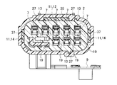
- FIG. 4A is a top view of the connector according to the embodiment of the present invention.
- 4B is a cross-sectional view taken along line AA in FIG. 4A.
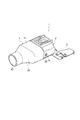
- FIG. 5 is a perspective view showing a state in the middle of assembly of the connector according to the modification of the embodiment of the present invention.
- FIG. 6 is a perspective view showing an assembled state of the connector according to the modification of the embodiment of the present invention.
- the direction approaching the mating connector is defined as the front side
- the direction away from the mating connector is defined as the rear side.
- the connector 1 includes a female connector 2, a male connector 3, a wire regulating cover 4, and a packing 5.
- the female connector 2 has a fitting hood portion 6 from which a male terminal portion 7 projects.
- the male connector 3 includes a female terminal accommodating portion 19 that accommodates a female terminal (not shown) that is fitted to the fitting hood portion 6 of the female connector 2 and connected to the male terminal portion 7 of the female connector 2.
- the plurality of electric wires are connected to the female terminals of the female terminal accommodating portion 19 and are drawn out from the electric wire drawing side (rear end portion) of the male connector 3.
- the electric wire restriction cover 4 is attached to the electric wire drawing side of the male connector 3 and converges a plurality of electric wires drawn from the male connector 3 to the outside.
- the packing 5 is disposed in the female connector 2 and is sandwiched between the bottom wall 10 of the female connector 2 and the end of the male connector 3.
- the female connector 2 further includes a male terminal accommodating portion 16 and a mounting portion 9.
- the male terminal accommodating portion 16 is fitted into the fitting hood portion 6 of the female connector 2 and accommodates the male terminal portion 7 connected to the female terminal.
- the attachment portion 9 is formed at one end of the female connector 2.
- the fitting hood portion 6 is formed in a substantially rectangular tube shape having an opening on one side, and has a side wall 8 and a bottom wall 10.
- the male connector guide groove 13 that guides insertion of the male connector 3 and the protrusion insertion groove 11 into which the protrusion 29 of the wire restriction cover 4 is inserted are the male connector 3 and the wire restriction. It is formed along the insertion direction of the cover 4.
- a lock means 18 for attaching another connector to the attachment location is formed on the outer peripheral side of the side wall 8.
- the packing 5 is disposed in contact with the bottom wall 10 on the inner peripheral side of the fitting hood portion 6.
- the protrusion insertion groove 11 formed on the inner peripheral side of the side wall 8 is formed so as to protrude from the inner wall side of the side wall 8 to the outer wall side.
- the protrusions 29 of the wire restriction cover 4 are press-fitted into the protrusion insertion grooves 11 respectively.
- the male terminal accommodating portion 16 is formed inside the fitting hood portion 6 and accommodates the male terminal portion 7.
- the male terminal portion 7 is disposed in the male terminal accommodating portion 16 so as to protrude from the bottom wall 10 to the opening side.
- the attachment portion 9 extends from the side wall 8 of the female connector 2 and is attached to a desired attachment location of the side wall 8.
- the male connector 3 has a female terminal accommodating portion 19.
- the female terminal accommodating portion 19 has a main body portion 17 having an outer diameter formed to be approximately the same size as the inner diameter of the male terminal accommodating portion 16 at the front end portion, and accommodates a female terminal (not shown).
- the main body portion 17 is formed in substantially the same shape as the inner periphery of the fitting hood portion 6 and is inserted into the male terminal accommodating portion 16 of the female connector 2.
- the female terminal accommodated in the female terminal accommodating portion 19 is electrically connected to the male terminal portion 7 of the female connector 2.
- the male connector 3 has a protrusion insertion guide part 25 and a guide protrusion 27.
- the protruding portion insertion guide portion 25 is erected along the female terminal accommodating portion 19 of the male connector 3.
- the guide protrusion 27 is formed on the outer periphery of the main body portion 17 and guides the insertion of the male connector 3 into the female connector 2.
- a plurality of guide protrusions 27 are provided on the outer peripheral surface 20 of the main body portion 17.
- the protrusion insertion guide part 25 has a fixing part 31 fixed to the wire restriction cover 4 and a recess 33 for guiding the assembly of the wire restriction cover 4.
- the fixing portion 31 protrudes in a direction orthogonal to the insertion direction of the male connector 3 to the female connector 2.
- the fixing portion 31 is fixed to fixing means (not shown) formed inside the electric wire restriction cover 4 to fix the male connector 3 to the electric wire restriction cover 4.
- the concave portion 33 is provided in the female terminal accommodating portion 19 together with the fixing portion 31.
- the recess 33 is recessed along the insertion direction so as to guide the insertion of the protrusion 29 of the wire restriction cover 4 into the female connector 2.
- the wire restriction cover 4 has a cover main body portion 21, a wire converging portion 22, and a wire insertion hole 23.
- the cover main body portion 21 covers the rear end side of the female terminal accommodating portion 19 of the male connector 3.
- the electric wire converging unit 22 condenses a plurality of electric wires drawn out of the male connector 3.
- the electric wire insertion hole 23 pulls out the plurality of electric wires converged by the electric wire converging unit 22 to the outside.
- the cover body portion 21 is attached to the male connector 3 so as to cover the rear end side of the female terminal accommodating portion 19. Further, a protrusion 29 is erected on the front side (front end) of the cover main body 21 in the assembling / inserting direction. The thickness of the protrusion 29 is set to be larger than the protrusion height of the protrusion insertion groove 11 formed in the female connector 2.
- the protrusion 29 on the cover main body 21 includes one long side protrusion 35 provided on the long side of the wire restriction cover 4 and two short sides provided on the short side of the wire restriction cover 4. This is a side projection 37.
- a regulating portion that is regulated by the concave portion 33 of the protruding portion insertion guide portion 25 may be provided on the inner wall side of the protruding portion 29.
- an inclined surface may be provided on the distal end portion 36 of the long side projection portion 35 and the distal end portion 38 of the short side projection portion 37 in order to facilitate assembly.
- the electric wire converging part 22 is connected to the cover main body part 21.
- An inclined surface is formed on the inner surface of the electric wire converging portion 22 toward the electric wire insertion hole 23 in order to converge a plurality of electric wires toward the electric wire insertion hole 23.
- the electric wire insertion hole 23 is connected to the electric wire converging part 22.
- the electric wire insertion hole 23 pulls out the plurality of electric wires converged by the electric wire converging unit 22 to the outside.
- the packing 5 is attached to the bottom wall 10 of the female connector 2, and the male connector 3 is inserted into the female connector 2.
- the guide protrusion 27 of the male connector 3 is inserted into the male connector guide groove 13 formed on the inner peripheral side of the side wall 8 of the fitting hood 6.
- the male terminal portion 7 is electrically connected to the female terminal by inserting the main body portion 17 of the female terminal accommodating portion 19 of the male connector 3 into the male terminal accommodating portion 16 of the female connector 2. Is done.
- the wire restriction cover 4 is attached to the male connector 3 so as to cover the rear end portion of the female terminal accommodating portion 19 of the male connector 3.
- the projection of the female connector 2 is inserted while sliding the short side projection 37 of the projection 29 provided in the opening of the wire regulating cover 4 into the recess 33 of the projection insertion guide 25 of the male connector 3.
- a short side protrusion 37 is press-fitted between the groove 11 (short side insertion groove 14) and the outer peripheral surface 20 of the main body 17 of the male connector 3.
- the long side protrusion 35 of the protrusion 29 is connected to the outer peripheral surface 20 of the main body 17 of the male connector 3 and the protrusion insertion groove 11 ( Press fit between the long side insertion groove 12).
- the cover main body 21 is formed with the protrusion 29 to be inserted between the protrusion insertion groove 11 of the female connector 2 and the outer peripheral surface 20 of the main body 17 of the male connector 3.
- the protruding portion 29 formed on the wire restriction cover 4 is inserted into the gap generated between the male connector 3 and the female connector 2, and thus the gap generated between the male connector 3 and the female connector 2 is projected.
- the portion 29 can be filled.
- the thickness of the protruding portion 29 larger than the protruding height of the protruding portion insertion groove 11, the gap between the female connector 2 and the male connector 3 can be reliably filled, and the male connector 3 is connected to the female connector 2. Can be prevented from vibrating inside.
- a protrusion 29 formed on the cover main body 21 is formed between the protrusion insertion groove 11 of the female connector 2 and the outer peripheral surface 20 of the main body 17 of the male connector 3. Since the protrusion insertion guide part 25 for guiding the gap between the protrusions 29 is formed, the protrusion 29 can be reliably guided to the protrusion insertion groove 11.
- a locking piece 39 protruding toward the fitting hood portion 6 is provided on the short side protrusion portion 37 of the protrusion portion 29 of the wire regulating cover 4.
- the engaging portion 15 may be provided on the side wall 8 of the female connector 2.
- the tip of the locking piece 39 may be tapered so that the tip of the locking piece 39 gradually rises from the insertion side toward the insertion rear side. Thereby, the locking piece 39 is easily locked to the locking portion 15.
- the present invention can be used for a connector using a cover that covers the connector.
Landscapes
- Details Of Connecting Devices For Male And Female Coupling (AREA)
- Connector Housings Or Holding Contact Members (AREA)
Description
本発明は、コネクタに関し、特に、電線規制カバーが装着されるコネクタに関する。
従来のコネクタは、雄コネクタと雌コネクタとで形成される。雄コネクタは雌コネクタに嵌合される。雄コネクタ及び雌コネクタのうち、一方のコネクタ内には端子が配置され、他方のコネクタ内には導電部材が収容される。一方のコネクタの端子が他方のコネクタの導電部材に接触すると、導電部材は端子に電気的に接続される。導電部材に電気を流すための複数の電線は一方のコネクタの端子に接続されている。複数の電線は、一方のコネクタの一端側(電線引出側)から外部に引き出される。電線規制カバーは、一方のコネクタの電線引出側に取り付けられている。電線規制カバーは、外部に引き出された複数の電線を集束して(特許文献1を参照)、複数の電線の動きを一方向に規制する。
しかしながら、従来のコネクタでは、電線規制カバーを雄コネクタ又は雌コネクタの電線引出側に取り付けた際に、電線規制カバーを取り付けた側のコネクタの重量が増す。そのため、雄コネクタを雌コネクタに嵌合した際に、雌コネクタの内壁と雄コネクタの外周面との間に隙間が生じている場合、電線規制カバーを取り付けた側のコネクタが振動しやすくなり、電線規制カバーを取り付けた側のコネクタの耐振性が低下するという問題があった。
本発明は、電線引出側(コネクタの後端側)に電線規制カバーが取り付けられたコネクタの耐振性を向上させるコネクタを提供することを目的としている。
本発明の第1態様によれば、内部で雄端子部7が突出する嵌合フード部6を有する雌コネクタと、前記雌コネクタの前記嵌合フード部に嵌合し、かつ、前記雌コネクタの前記雄端子部7に接続される雌端子を収容する雌側端子収容部を有する雄コネクタと、複数の電線は、前記雌端子に接続されて、前記雄コネクタの後端部から引き出され、前記雄コネクタの前記後端部に取り付けられて、前記雄コネクタから引き出された複数の電線を集束する電線規制カバーと、を備え、前記雌コネクタの前記嵌合フード部の内壁には、前記雄コネクタの挿入方向に沿って突起部挿入溝が形成され、前記電線規制カバーには、前記雄コネクタの前記後端部を覆うカバー本体部が形成され、前記カバー本体部の前端部には、前記雌コネクタの前記突起部挿入溝と前記雄コネクタの外周面との間に挿入されて、前記嵌合フード部の前記内壁と前記雄コネクタの前記外周面との隙間を埋める突起部が形成されていることを特徴とするコネクタを提供する。
本発明の第2態様によれば、前記突起部には、前記雌コネクタの前記嵌合フード部側に突出する係止片が設けられ、前記雌コネクタの前記嵌合フード部に、前記係止片が係止される係止部が設けられ、前記係止片を前記係止部に係止することにより、前記電線規制カバーが前記雄コネクタに組み付けられる。
本発明の第3態様によれば、前記雄コネクタの前記後端部に、前記突起部を、前記嵌合フード部の前記内壁と前記雄コネクタの前記外周面との隙間に案内する突起部挿入案内部が形成されている。
本発明の第1態様によれば、カバー本体部の前端部には、雌コネクタの突起部挿入溝と雄コネクタの外周面との間に挿入されて、嵌合フード部の内壁と雄コネクタの外周面との隙間を埋める突起部が形成されている。それゆえ、雄コネクタと雌コネクタとの間に生じる隙間に、電線規制カバーに形成された突起部を挿入することにより、雄コネクタ3と雌コネクタ2との間に生じる隙間を突起部29によって埋めることができる。
本発明の第2態様によれば、突起部に設けられた係止片が、雌コネクタの側壁に形成された係止部に係止されるので、電線規制カバーを確実に雌コネクタに係止することができる。
本発明の第3態様によれば、雄コネクタの後端部に、突起部を、嵌合フード部の内壁と雄コネクタの外周面との隙間に案内する突起部挿入案内部が形成されている。それゆえ、突起部を確実に突起部挿入溝に案内することができる。
以下、本発明の実施の形態について、図1~6を用いて詳細に説明する。本実施形態では、相手コネクタに近づく方向を前側とし、相手コネクタから離れる方向を後側と定義する。
図1~4Bに示すように、コネクタ1は、雌コネクタ2、雄コネクタ3、電線規制カバー4、パッキン5を備える。雌コネクタ2は、内部で雄端子部7が突出する嵌合フード部6を有する。雄コネクタ3は、雌コネクタ2の嵌合フード部6に嵌合し、かつ、雌コネクタ2の雄端子部7に接続される雌端子(図示略)を収容する雌端子収容部19を有する。複数の電線は、雌端子収容部19の雌端子に接続されて、雄コネクタ3の電線引出側(後端部)から外部に引き出される。電線規制カバー4は、雄コネクタ3の電線引出側に取り付けられて、雄コネクタ3から外部に引き出された複数の電線を集束する。パッキン5は、雌コネクタ2内に配置されて、雌コネクタ2の底面壁10と雄コネクタ3の端部との間で狭持される。
雌コネクタ2は、雄端子収容部16及び取付部9を更に有する。雄端子収容部16は、雌コネクタ2の嵌合フード部6に嵌合して、雌端子に接続される雄端子部7を収容する。取付部9は、雌コネクタ2の一端に形成される。
嵌合フード部6は、一面側を開口した略角筒状に形成されており、側壁8と底面壁10を有する。側壁8の内周側には、雄コネクタ3の挿入をガイドする雄コネクタガイド溝13と、電線規制カバー4の突起部29が挿入される突起部挿入溝11と、が雄コネクタ3及び電線規制カバー4の挿入方向に沿って形成されている。側壁8の外周側には、他のコネクタを取り付け箇所に取り付けるためのロック手段18が形成されている。嵌合フード部6の内周側の底面壁10には、パッキン5が当接して配置される。
側壁8の内周側に形成される突起部挿入溝11は、側壁8の内壁側から外壁側へ突出するように形成されている。突起部挿入溝11には、電線規制カバー4の突起部29がそれぞれ圧入される。
雄端子収容部16は、嵌合フード部6の内側に形成されて、雄端子部7を収容する。雄端子部7は、雄端子収容部16内で底面壁10から開口側に突出するように配置されている。
取付部9は、雌コネクタ2の側壁8から延設されて、側壁8の所望の取り付け箇所に取り付けられる。
雄コネクタ3は雌端子収容部19を有する。雌端子収容部19は、雄端子収容部16の内径とほぼ同じ大きさに外径が形成された本体部17を前端部に有し、かつ、雌端子(図示略)を収容する。
本体部17は、嵌合フード部6の内周と略同形状に形成されて、雌コネクタ2の雄端子収容部16に挿入される。
雌端子収容部19に収容された雌端子は、雌コネクタ2の雄端子部7と電気的に接続される。
雄コネクタ3は、突起部挿入案内部25及びガイド突起27を有する。突起部挿入案内部25は、雄コネクタ3の雌端子収容部19に沿って立設される。ガイド突起27は、本体部17の外周に形成されて、雌コネクタ2への雄コネクタ3の挿入をガイドする。ガイド突起27は、本体部17の外周面20に複数箇所設けられている。
突起部挿入案内部25は、電線規制カバー4に固定される固定部31と、電線規制カバー4の組み付けを案内する凹部33を有する。
固定部31は、雌コネクタ2への雄コネクタ3の挿入方向に直交する方向に突設されている。固定部31は、電線規制カバー4の内部に形成された固定手段(図示略)に固定されて、雄コネクタ3を電線規制カバー4に固定する。
凹部33は、固定部31とともに雌端子収容部19に設けられる。凹部33は、雌コネクタ2への電線規制カバー4の突起部29の挿入を案内するように、挿入方向に沿って凹設されている。
図2に示すように、電線規制カバー4は、カバー本体部21、電線集束部22、電線挿通孔23を有する。カバー本体部21は、雄コネクタ3の雌端子収容部19の後端側を覆う。電線集束部22は、雄コネクタ3の外部に引き出された複数の電線を集束する。電線挿通孔23は、電線集束部22によって集束された複数の電線を外部に引き出す。
カバー本体部21は、雌端子収容部19の後端側を覆うように、雄コネクタ3に取り付けられる。また、カバー本体部21の組み付け挿入方向の前方側(前端部)には、突起部29が立設されている。突起部29の厚さは、雌コネクタ2に形成された突起部挿入溝11の突出高さより大きく設定されている。
突起部29は、カバー本体部21の挿入方向の前方側(前端部)に複数箇所設けることが好ましい。本実施形態では、カバー本体部21に突起部29は、電線規制カバー4の長辺に設けられた1つの長辺側突起部35と、電線規制カバー4の短辺に設けられた2つの短辺側突起部37である。
突起部29の内壁側に、突起部挿入案内部25の凹部33によって規制される規制部を設けてもよい。また、長辺側突起部35の先端部36及び短辺側突起部37の先端部38に、組み付けを容易にするために傾斜面を設けてもよい。
電線集束部22はカバー本体部21に連設される。電線集束部22の内面には、電線挿通孔23に向けて複数の電線を集束するために、電線挿通孔23に向けて傾斜面が形成されている。
電線挿通孔23は電線集束部22に連設される。電線挿通孔23は、電線集束部22によって集束された複数の電線を外部に引き出す。
次に、コネクタの組み付け方法について説明する。
まず、雌コネクタ2の底面壁10にパッキン5を取り付けて、雄コネクタ3を雌コネクタ2に挿入する。雄コネクタ3を雌コネクタ2に挿入する際、嵌合フード部6の側壁8の内周側に形成された雄コネクタガイド溝13に、雄コネクタ3のガイド突起27を挿入する。
そして、図2に示すように、雄コネクタ3の雌端子収容部19の本体部17を雌コネクタ2の雄端子収容部16に挿入することで、雄端子部7が雌端子に電気的に接続される。
この状態で、雄コネクタ3の雌端子収容部19の後端部を覆うように電線規制カバー4を雄コネクタ3に取り付ける。この際、電線規制カバー4の開口に設けられた突起部29の短辺側突起部37を雄コネクタ3の突起部挿入案内部25の凹部33に摺動させながら、雌コネクタ2の突起部挿入溝11(短辺側挿入溝14)と雄コネクタ3の本体部17の外周面20との間に短辺側突起部37を圧入する。なお、短辺側突起部37を短辺側挿入溝14に圧入すると同時に、突起部29の長辺側突起部35を、雄コネクタ3の本体部17の外周面20と突起部挿入溝11(長辺側挿入溝12)との間に圧入する。
上記のように、カバー本体部21には、雌コネクタ2の突起部挿入溝11と雄コネクタ3の本体部17の外周面20との間に挿入されるべき突起部29が形成されている。これにより、雄コネクタ3と雌コネクタ2との間に生じる隙間に、電線規制カバー4に形成された突起部29が挿入されるため、雄コネクタ3と雌コネクタ2との間に生じる隙間を突起部29によって埋めることができる。加えて、突起部29の厚さを突起部挿入溝11の突出高さよりも大きくすることで、雌コネクタ2と雄コネクタ3との隙間を確実に埋めることができ、雄コネクタ3が雌コネクタ2内で振動することを防止することができる。
雄コネクタ3の雌端子収容部19の側面には、カバー本体部21に形成される突起部29を、雌コネクタ2の突起部挿入溝11と雄コネクタ3の本体部17の外周面20との間の隙間に案内する突起部挿入案内部25が形成されているため、突起部29を確実に突起部挿入溝11に案内することができる。
なお、本実施形態の変形例として、図5,6に示すように、電線規制カバー4の突起部29の短辺側突起部37に、嵌合フード部6側に突出する係止片39を設けて、かつ、雌コネクタ2の側壁8に係止部15を設けても良い。
すなわち、係止片39が係止部15に係止することにより、電線規制カバー4が雌コネクタ2に確実に係止されるので、突起部29が突起部挿入溝11から抜け出ることを防止することができる。
また、係止片39の先端が挿入側から挿入後方側に向けて徐々に隆起するように、係止片39の先端をテーパ形状にしてもよい。これにより、係止片39を係止部15へ容易に係止される。
本発明は、コネクタを覆うカバーを用いるコネクタに利用することができる。
1 コネクタ
2 雌コネクタ
3 雄コネクタ
4 電線規制カバー
7 雄端子部
11 突起部挿入溝
17 本体部
19 雌端子収容部
20 外周面
21 カバー本体部
29 突起部
2 雌コネクタ
3 雄コネクタ
4 電線規制カバー
7 雄端子部
11 突起部挿入溝
17 本体部
19 雌端子収容部
20 外周面
21 カバー本体部
29 突起部
Claims (3)
- 内部で雄端子部が突出する嵌合フード部を有する雌コネクタと、
前記雌コネクタの前記嵌合フード部に嵌合し、かつ、前記雌コネクタの前記雄端子部に接続される雌端子を収容する雌端子収容部を有する雄コネクタと、
複数の電線は、前記雌端子に接続されて、前記雄コネクタの後端部から引き出され、
前記雄コネクタの前記後端部に取り付けられて、前記雄コネクタから引き出された複数の電線を集束する電線規制カバーと、
を備え、
前記雌コネクタの前記嵌合フード部の内壁には、前記雄コネクタの挿入方向に沿って突起部挿入溝が形成され、
前記電線規制カバーには、前記雄コネクタの前記後端部を覆うカバー本体部が形成され、
前記カバー本体部の前端部には、前記雌コネクタの前記突起部挿入溝と前記雄コネクタの外周面との間に挿入されて、前記嵌合フード部の前記内壁と前記雄コネクタの前記外周面との隙間を埋める突起部が形成されていることを特徴とするコネクタ。 - 前記突起部には、前記雌コネクタの前記嵌合フード部側に突出する係止片が設けられ、
前記雌コネクタの前記嵌合フード部に、前記係止片が係止される係止部が設けられ、
前記係止片を前記係止部に係止することにより、前記電線規制カバーが前記雄コネクタに組み付けられることを特徴とする請求項1に記載のコネクタ。 - 前記雄コネクタの前記後端部に、前記突起部を、前記嵌合フード部の前記内壁と前記雄コネクタの前記外周面との隙間に案内する突起部挿入案内部が形成されていることを特徴とする請求項1又は2に記載のコネクタ。
Priority Applications (3)
| Application Number | Priority Date | Filing Date | Title |
|---|---|---|---|
| KR1020157007926A KR20150048222A (ko) | 2012-09-07 | 2013-09-03 | 커넥터 |
| CN201380046607.7A CN104604043A (zh) | 2012-09-07 | 2013-09-03 | 连接器 |
| US14/636,875 US20150180163A1 (en) | 2012-09-07 | 2015-03-03 | Connector |
Applications Claiming Priority (2)
| Application Number | Priority Date | Filing Date | Title |
|---|---|---|---|
| JP2012-196881 | 2012-09-07 | ||
| JP2012196881A JP5946377B2 (ja) | 2012-09-07 | 2012-09-07 | コネクタ |
Related Child Applications (1)
| Application Number | Title | Priority Date | Filing Date |
|---|---|---|---|
| US14/636,875 Continuation US20150180163A1 (en) | 2012-09-07 | 2015-03-03 | Connector |
Publications (1)
| Publication Number | Publication Date |
|---|---|
| WO2014038543A1 true WO2014038543A1 (ja) | 2014-03-13 |
Family
ID=50237152
Family Applications (1)
| Application Number | Title | Priority Date | Filing Date |
|---|---|---|---|
| PCT/JP2013/073668 Ceased WO2014038543A1 (ja) | 2012-09-07 | 2013-09-03 | コネクタ |
Country Status (5)
| Country | Link |
|---|---|
| US (1) | US20150180163A1 (ja) |
| JP (1) | JP5946377B2 (ja) |
| KR (1) | KR20150048222A (ja) |
| CN (1) | CN104604043A (ja) |
| WO (1) | WO2014038543A1 (ja) |
Families Citing this family (8)
| Publication number | Priority date | Publication date | Assignee | Title |
|---|---|---|---|---|
| JP6334456B2 (ja) * | 2015-04-30 | 2018-05-30 | 矢崎総業株式会社 | コネクタ及びその製造方法 |
| JP6275104B2 (ja) * | 2015-12-11 | 2018-02-07 | 矢崎総業株式会社 | コネクタ構造 |
| JP6889840B2 (ja) * | 2017-11-08 | 2021-06-18 | 株式会社オートネットワーク技術研究所 | コネクタ |
| DE102018101431A1 (de) * | 2018-01-23 | 2019-07-25 | Neutrik Ag | Steckverbindung |
| JP7428973B2 (ja) * | 2020-09-28 | 2024-02-07 | 住友電装株式会社 | コネクタ |
| US11837806B2 (en) * | 2020-12-09 | 2023-12-05 | Lear Corporation | Grounding electrical connector |
| JP7777363B1 (ja) * | 2024-10-03 | 2025-11-28 | 株式会社水素パワー | 誤接続検知構造 |
| JP7750574B1 (ja) * | 2024-10-03 | 2025-10-07 | 株式会社水素パワー | 誤接続防止構造 |
Citations (4)
| Publication number | Priority date | Publication date | Assignee | Title |
|---|---|---|---|---|
| JPH1027645A (ja) * | 1996-07-12 | 1998-01-27 | Sumitomo Wiring Syst Ltd | コネクタ |
| JP2004172067A (ja) * | 2002-11-22 | 2004-06-17 | Sumitomo Wiring Syst Ltd | コネクタ |
| JP2007250397A (ja) * | 2006-03-16 | 2007-09-27 | Sumitomo Wiring Syst Ltd | コネクタ |
| JP2012511804A (ja) * | 2008-12-12 | 2012-05-24 | タイコ・エレクトロニクス・コーポレイション | 張力逃し機構を備えたコネクタ組立体 |
Family Cites Families (13)
| Publication number | Priority date | Publication date | Assignee | Title |
|---|---|---|---|---|
| JP2582750Y2 (ja) * | 1992-10-06 | 1998-10-08 | 住友電装株式会社 | コネクタ用カバー |
| US5709560A (en) * | 1994-12-14 | 1998-01-20 | Sumitomo Wiring Systems, Ltd. | Connector having a pivotable connection-assistance member |
| DE19513358C1 (de) * | 1995-04-08 | 1996-08-08 | Amphenol Tuchel Elect | Elektrischer Steckverbinder |
| JPH11224728A (ja) * | 1998-02-04 | 1999-08-17 | Yazaki Corp | 半嵌合防止コネクタ |
| JP3472700B2 (ja) * | 1998-03-25 | 2003-12-02 | 矢崎総業株式会社 | コネクタの嵌合構造 |
| JP3726641B2 (ja) * | 2000-05-23 | 2005-12-14 | 住友電装株式会社 | レバー式コネクタ |
| US7021959B2 (en) * | 2002-11-22 | 2006-04-04 | Sumitomo Wiring Systems, Ltd. | Wire cover with two longitudinal halves connectable around electric wires |
| JP3991275B2 (ja) * | 2003-05-20 | 2007-10-17 | 住友電装株式会社 | 電線カバー |
| JP2008108487A (ja) * | 2006-10-24 | 2008-05-08 | Sumitomo Wiring Syst Ltd | コネクタ |
| US7537478B2 (en) * | 2007-07-18 | 2009-05-26 | Tyco Electronics Corporation | Wire management cover and system |
| JP5316306B2 (ja) * | 2009-08-17 | 2013-10-16 | 住友電装株式会社 | コネクタ |
| JP5500680B2 (ja) * | 2010-03-26 | 2014-05-21 | タイコエレクトロニクスジャパン合同会社 | レバー式電気コネクタ |
| JP5598384B2 (ja) * | 2011-03-04 | 2014-10-01 | 住友電装株式会社 | コネクタ |
-
2012
- 2012-09-07 JP JP2012196881A patent/JP5946377B2/ja active Active
-
2013
- 2013-09-03 KR KR1020157007926A patent/KR20150048222A/ko not_active Withdrawn
- 2013-09-03 CN CN201380046607.7A patent/CN104604043A/zh active Pending
- 2013-09-03 WO PCT/JP2013/073668 patent/WO2014038543A1/ja not_active Ceased
-
2015
- 2015-03-03 US US14/636,875 patent/US20150180163A1/en not_active Abandoned
Patent Citations (4)
| Publication number | Priority date | Publication date | Assignee | Title |
|---|---|---|---|---|
| JPH1027645A (ja) * | 1996-07-12 | 1998-01-27 | Sumitomo Wiring Syst Ltd | コネクタ |
| JP2004172067A (ja) * | 2002-11-22 | 2004-06-17 | Sumitomo Wiring Syst Ltd | コネクタ |
| JP2007250397A (ja) * | 2006-03-16 | 2007-09-27 | Sumitomo Wiring Syst Ltd | コネクタ |
| JP2012511804A (ja) * | 2008-12-12 | 2012-05-24 | タイコ・エレクトロニクス・コーポレイション | 張力逃し機構を備えたコネクタ組立体 |
Also Published As
| Publication number | Publication date |
|---|---|
| US20150180163A1 (en) | 2015-06-25 |
| KR20150048222A (ko) | 2015-05-06 |
| JP2014053167A (ja) | 2014-03-20 |
| CN104604043A (zh) | 2015-05-06 |
| JP5946377B2 (ja) | 2016-07-06 |
Similar Documents
| Publication | Publication Date | Title |
|---|---|---|
| JP5946377B2 (ja) | コネクタ | |
| JP5670720B2 (ja) | コネクタ | |
| JP6371368B2 (ja) | 直角ヘッダアセンブリ | |
| US9543707B2 (en) | Connector case and shell securement | |
| JP6325505B2 (ja) | コネクタ | |
| WO2018163788A1 (ja) | シールド端子及びシールドコネクタ | |
| KR20160026746A (ko) | 커넥터 조립체 | |
| JP6741213B2 (ja) | コネクタ | |
| JP2014170709A (ja) | 雌端子金具 | |
| JP2017045572A (ja) | コネクタ | |
| WO2018012182A1 (ja) | コネクタ | |
| US10256574B2 (en) | Connector and shielding shell | |
| WO2014142245A1 (ja) | 電子部品の組付構造及び電気接続箱 | |
| JP6146618B2 (ja) | コネクタ | |
| CN108140974B (zh) | 端子 | |
| US20180226745A1 (en) | Wire cover member | |
| JP2011054433A (ja) | 防水コネクタ | |
| EP4117123A1 (en) | Connector fitting structure | |
| JP2010225371A (ja) | コネクタ | |
| JP2014229376A (ja) | シールドコネクタ | |
| JP5104639B2 (ja) | コネクタ | |
| JP5681478B2 (ja) | コネクタ | |
| JP3169822U (ja) | コネクタ | |
| JP2010067432A (ja) | コネクタ | |
| JP2012234635A (ja) | コネクタ |
Legal Events
| Date | Code | Title | Description |
|---|---|---|---|
| 121 | Ep: the epo has been informed by wipo that ep was designated in this application |
Ref document number: 13835781 Country of ref document: EP Kind code of ref document: A1 |
|
| NENP | Non-entry into the national phase |
Ref country code: DE |
|
| ENP | Entry into the national phase |
Ref document number: 20157007926 Country of ref document: KR Kind code of ref document: A |
|
| 122 | Ep: pct application non-entry in european phase |
Ref document number: 13835781 Country of ref document: EP Kind code of ref document: A1 |