WO2014038428A1 - 画像処理装置及び画像処理方法 - Google Patents
画像処理装置及び画像処理方法 Download PDFInfo
- Publication number
- WO2014038428A1 WO2014038428A1 PCT/JP2013/072802 JP2013072802W WO2014038428A1 WO 2014038428 A1 WO2014038428 A1 WO 2014038428A1 JP 2013072802 W JP2013072802 W JP 2013072802W WO 2014038428 A1 WO2014038428 A1 WO 2014038428A1
- Authority
- WO
- WIPO (PCT)
- Prior art keywords
- threshold
- image
- determination
- pixel
- image processing
- Prior art date
- Legal status (The legal status is an assumption and is not a legal conclusion. Google has not performed a legal analysis and makes no representation as to the accuracy of the status listed.)
- Ceased
Links
Images



Classifications
-
- G—PHYSICS
- G06—COMPUTING OR CALCULATING; COUNTING
- G06T—IMAGE DATA PROCESSING OR GENERATION, IN GENERAL
- G06T7/00—Image analysis
- G06T7/10—Segmentation; Edge detection
- G06T7/136—Segmentation; Edge detection involving thresholding
-
- A—HUMAN NECESSITIES
- A61—MEDICAL OR VETERINARY SCIENCE; HYGIENE
- A61B—DIAGNOSIS; SURGERY; IDENTIFICATION
- A61B6/00—Apparatus or devices for radiation diagnosis; Apparatus or devices for radiation diagnosis combined with radiation therapy equipment
- A61B6/50—Apparatus or devices for radiation diagnosis; Apparatus or devices for radiation diagnosis combined with radiation therapy equipment specially adapted for specific body parts; specially adapted for specific clinical applications
- A61B6/501—Apparatus or devices for radiation diagnosis; Apparatus or devices for radiation diagnosis combined with radiation therapy equipment specially adapted for specific body parts; specially adapted for specific clinical applications for diagnosis of the head, e.g. neuroimaging or craniography
-
- A—HUMAN NECESSITIES
- A61—MEDICAL OR VETERINARY SCIENCE; HYGIENE
- A61B—DIAGNOSIS; SURGERY; IDENTIFICATION
- A61B6/00—Apparatus or devices for radiation diagnosis; Apparatus or devices for radiation diagnosis combined with radiation therapy equipment
- A61B6/52—Devices using data or image processing specially adapted for radiation diagnosis
- A61B6/5211—Devices using data or image processing specially adapted for radiation diagnosis involving processing of medical diagnostic data
- A61B6/5217—Devices using data or image processing specially adapted for radiation diagnosis involving processing of medical diagnostic data extracting a diagnostic or physiological parameter from medical diagnostic data
-
- G—PHYSICS
- G06—COMPUTING OR CALCULATING; COUNTING
- G06T—IMAGE DATA PROCESSING OR GENERATION, IN GENERAL
- G06T7/00—Image analysis
- G06T7/0002—Inspection of images, e.g. flaw detection
- G06T7/0012—Biomedical image inspection
-
- G—PHYSICS
- G06—COMPUTING OR CALCULATING; COUNTING
- G06T—IMAGE DATA PROCESSING OR GENERATION, IN GENERAL
- G06T7/00—Image analysis
- G06T7/10—Segmentation; Edge detection
- G06T7/11—Region-based segmentation
-
- G—PHYSICS
- G06—COMPUTING OR CALCULATING; COUNTING
- G06T—IMAGE DATA PROCESSING OR GENERATION, IN GENERAL
- G06T7/00—Image analysis
- G06T7/10—Segmentation; Edge detection
- G06T7/187—Segmentation; Edge detection involving region growing; involving region merging; involving connected component labelling
-
- G—PHYSICS
- G16—INFORMATION AND COMMUNICATION TECHNOLOGY [ICT] SPECIALLY ADAPTED FOR SPECIFIC APPLICATION FIELDS
- G16H—HEALTHCARE INFORMATICS, i.e. INFORMATION AND COMMUNICATION TECHNOLOGY [ICT] SPECIALLY ADAPTED FOR THE HANDLING OR PROCESSING OF MEDICAL OR HEALTHCARE DATA
- G16H50/00—ICT specially adapted for medical diagnosis, medical simulation or medical data mining; ICT specially adapted for detecting, monitoring or modelling epidemics or pandemics
- G16H50/30—ICT specially adapted for medical diagnosis, medical simulation or medical data mining; ICT specially adapted for detecting, monitoring or modelling epidemics or pandemics for calculating health indices; for individual health risk assessment
-
- A—HUMAN NECESSITIES
- A61—MEDICAL OR VETERINARY SCIENCE; HYGIENE
- A61B—DIAGNOSIS; SURGERY; IDENTIFICATION
- A61B6/00—Apparatus or devices for radiation diagnosis; Apparatus or devices for radiation diagnosis combined with radiation therapy equipment
- A61B6/46—Arrangements for interfacing with the operator or the patient
- A61B6/461—Displaying means of special interest
- A61B6/466—Displaying means of special interest adapted to display 3D data
-
- G—PHYSICS
- G06—COMPUTING OR CALCULATING; COUNTING
- G06T—IMAGE DATA PROCESSING OR GENERATION, IN GENERAL
- G06T2207/00—Indexing scheme for image analysis or image enhancement
- G06T2207/10—Image acquisition modality
- G06T2207/10004—Still image; Photographic image
-
- G—PHYSICS
- G06—COMPUTING OR CALCULATING; COUNTING
- G06T—IMAGE DATA PROCESSING OR GENERATION, IN GENERAL
- G06T2207/00—Indexing scheme for image analysis or image enhancement
- G06T2207/10—Image acquisition modality
- G06T2207/10072—Tomographic images
-
- G—PHYSICS
- G06—COMPUTING OR CALCULATING; COUNTING
- G06T—IMAGE DATA PROCESSING OR GENERATION, IN GENERAL
- G06T2207/00—Indexing scheme for image analysis or image enhancement
- G06T2207/30—Subject of image; Context of image processing
- G06T2207/30004—Biomedical image processing
-
- G—PHYSICS
- G06—COMPUTING OR CALCULATING; COUNTING
- G06T—IMAGE DATA PROCESSING OR GENERATION, IN GENERAL
- G06T2207/00—Indexing scheme for image analysis or image enhancement
- G06T2207/30—Subject of image; Context of image processing
- G06T2207/30004—Biomedical image processing
- G06T2207/30016—Brain
-
- G—PHYSICS
- G06—COMPUTING OR CALCULATING; COUNTING
- G06T—IMAGE DATA PROCESSING OR GENERATION, IN GENERAL
- G06T2207/00—Indexing scheme for image analysis or image enhancement
- G06T2207/30—Subject of image; Context of image processing
- G06T2207/30004—Biomedical image processing
- G06T2207/30101—Blood vessel; Artery; Vein; Vascular
Definitions
- the present invention relates to an image processing apparatus that recognizes a specific area from an image.
- a three-dimensional original image (three-dimensional volume data) is generated from a tomographic image group photographed by an X-ray CT (Computed Tomography) apparatus, an MRI (Magnetic Resonance Imaging) apparatus, etc.
- a diagnostic image A technique is known in which tissue is extracted or removed, and an image suitable for diagnosis (hereinafter referred to as a diagnostic image) is generated and displayed.
- a diagnostic image for example, a three-dimensional volume rendering image, a MIP (Maximum Intensity Projection) image, or the like is created.
- a bone-removed MIP image may be generated by removing a bone region including a skull, cartilage, and the like from the above-described tomographic image group.
- the extraction method for example, there is a region expansion method (region growing method) and the like.
- region expansion method when an operator designates a pixel to be a starting point on an image, the computer determines whether or not a predetermined threshold condition is satisfied for a pixel at the starting point or surrounding pixels including the pixel, When the condition is satisfied, the pixel is expanded as an extraction region.
- Patent Document 1 discloses a method for preventing excessive extraction due to slight pixel concatenation when performing region extraction by the region expansion method.
- the region is expanded only when a predetermined ratio of pixels in the sense region composed of a plurality of pixels continues to the extracted region and satisfies the condition.
- Patent Document 2 discloses a method for distinguishing cancellous bone, which is an internal tissue of bone, and tissue that is difficult to separate, such as bone marrow. Specifically, by obtaining a pixel value histogram of an MR image including cancellous bone and bone marrow, and fitting it with three normal distribution curves (cancellous bone, bone marrow, intermediate value between both), the two can be separated. It is described that the cancellous bone volume fraction is accurately calculated.
- the present invention has been made in view of the above problems, and in the process of recognizing a specific area from an image, a plurality of areas that exist in the image and have large density value fluctuations can be accurately obtained with a simple operation.
- An object is to provide an image processing apparatus and an image processing method that can be recognized.
- the first invention is an image processing device that executes processing for recognizing a specific region from an image, and includes a pixel of interest and a plurality of surrounding pixels among pixels included in the image.
- a threshold determination unit that applies a predetermined threshold condition to a determination range including a pixel and determines the target pixel as a recognition pixel when any of the pixels in the determination range satisfies the threshold condition;
- a process execution unit that sequentially moves the determination range and repeatedly executes the threshold determination.
- recognition means that the corresponding pixel is distinguished from other pixels in the three-dimensional original image.
- a specific method for example, (a) a specific value serving as a mark is directly written in the original three-dimensional original image. Alternatively, (b) recording the recognition pixels as a binary image in a memory different from the three-dimensional original image.
- a second invention is an image processing method for recognizing a specific region from an image using a computer, and for a determination range including a pixel of interest and a plurality of surrounding pixels among pixels included in the image.
- threshold determination is performed by applying a predetermined threshold condition, and the threshold condition is satisfied in any pixel in the determination range, threshold determination processing in which the target pixel is a recognition pixel is performed by sequentially moving the determination range.
- An image processing method characterized by being repeatedly executed.
- the image processing apparatus and image processing method of the present invention in the process of recognizing a specific area from an image, it is possible to accurately recognize a plurality of areas in the image and large density value fluctuations with a simple operation. It becomes. For example, image processing for removing the cartilage region can be performed more easily and accurately.
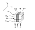
- the figure which shows the whole structure of the image processing apparatus 100 The figure which shows an example of the range (determination range 33) which is the attention pixel 31 in the three-dimensional original image 30 to be processed and the pixels around the attention pixel 31 and is the threshold determination target Flowchart for explaining the flow of diagnostic image generation processing executed by the image processing apparatus 100 according to the present invention Example of operation screen 20 It is a figure explaining how to apply the threshold condition in each processing mode, (a) is a stand-alone mode, (b) is an isotropic neighbor judgment mode, (c) is a figure explaining an anisotropic neighbor judgment mode The flowchart explaining the flow of the threshold determination process by anisotropic neighborhood determination mode The figure explaining the density value histogram used when a threshold value is automatically set (a) The figure explaining the symmetrical distribution curve 72 using the data of the left side (CT value low side) from the peak position of a density value histogram.
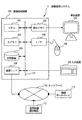
- the image processing system 1 includes an image processing device 100 having a display device 107 and an input device 109, an image database 111 connected to the image processing device 100 via a network 110, and a medical image photographing device. 112.
- the image processing apparatus 100 is a computer that performs processing such as image generation and image analysis.
- a medical image processing apparatus installed in a hospital or the like is included.
- the image processing apparatus 100 includes a CPU (Central Processing Unit) 101, a main memory 102, a storage device 103, a communication interface (communication I / F) 104, a display memory 105, a mouse 108, and other external devices. Interface (I / F) 106, and each unit is connected via a bus 113.
- CPU Central Processing Unit
- the CPU 101 calls and executes a program stored in the main memory 102 or the storage device 103 in the work memory area on the RAM of the main memory 102, executes driving control of each unit connected via the bus 113, and the image processing apparatus Implements various processes performed by 100.
- the CPU 101 performs processing for recognizing a specific area from the image to be processed in diagnostic image generation processing (see FIG. 3) described later.
- the image to be processed is a three-dimensional original image formed by stacking a plurality of tomographic images.
- the CPU 101 sets a plurality of pixels around the target pixel among the pixels included in the three-dimensional original image as a determination range, and applies a predetermined threshold condition to each pixel in the determination range. judge. When the threshold condition is satisfied, the target pixel is set as a recognition pixel.
- the CPU 101 performs the above-described threshold determination by scanning the entire three-dimensional original image. That is, by sequentially moving the determination range and repeatedly executing the above threshold determination, the threshold determination is performed on the entire three-dimensional original image.
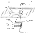
- the ⁇ multiple pixels around the target pixel (determination range) '' to be subjected to threshold determination is an X direction centered on the target pixel 31 included in the three-dimensional original image 30, as shown in FIG.
- the pixels are within a predetermined distance range in the Y direction and the slice (SLS) direction. That is, the pixel is located in the vicinity of the target pixel 31.
- the pixel of interest 31 to be subjected to threshold determination and a plurality of surrounding pixels are referred to as a determination range 33.
- the determination range 33 is a 3 ⁇ 3 ⁇ 3 pixel group in the slice (SLS) direction, the left / right (X) direction, and the depth (Y) direction with the target pixel 31 as the center.
- the width of the determination range 33 is not limited to this, and the determination range may be further expanded, such as a 5 ⁇ 3 ⁇ 3 pixel group.
- the main memory 102 is composed of ROM (Read Only Memory), RAM (Random Access Memory), and the like.
- ROM Read Only Memory
- RAM Random Access Memory
- the ROM permanently holds a computer boot program, a BIOS program, data, and the like.
- the RAM temporarily holds programs, data, and the like loaded from the ROM, the storage device 103, and the like, and includes a work memory area that the CPU 101 uses for performing various processes.
- the storage device 103 is a storage device that reads / writes data to / from an HDD (hard disk drive) or other recording medium, and stores programs executed by the CPU 101, data necessary for program execution, an OS (operating system), and the like. .
- As for the program a control program corresponding to the OS and an application program are stored. Each of these program codes is read by the CPU 101 as necessary, transferred to the RAM of the main memory 102, and operates as various execution units.
- the communication I / F 104 has a communication control device, a communication port, and the like, and mediates communication between the image processing apparatus 100 and the network 110.
- the communication I / F 104 performs communication control with the image database 111, another computer, or a medical image photographing apparatus 112 such as an X-ray CT apparatus or an MRI apparatus via the network 110.
- the I / F 106 is a port for connecting a peripheral device, and transmits / receives data to / from the peripheral device.
- a pointing device such as a mouse 108 or a stylus pen may be connected via the I / F 106.
- the display memory 105 is a buffer that temporarily stores display data input from the CPU 101.
- the accumulated display data is output to the display device 107 at a predetermined timing.
- the display device 107 includes a display device such as a liquid crystal panel and a CRT monitor, and a logic circuit for executing display processing in cooperation with the display device, and is connected to the CPU 101 via the display memory 105.
- the display device 107 displays the display data stored in the display memory 105 under the control of the CPU 101.
- the input device 109 is an input device such as a keyboard, for example, and outputs various instructions and information input by the operator to the CPU 101.
- the operator interactively operates the image processing apparatus 100 using external devices such as the display device 107, the input device 109, and the mouse 108.
- the network 110 includes various communication networks such as a LAN (Local Area Network), a WAN (Wide Area Network), an intranet, the Internet, and the like, and connects the image database 111, the server, other information devices, and the like to the image processing apparatus 100. Mediate.
- LAN Local Area Network
- WAN Wide Area Network
- intranet the Internet
- the image database 111 stores and stores image data captured by the medical image capturing device 112.
- the image database 111 is configured to be connected to the image processing apparatus 100 via the network 110.
- the image database 111 is provided in the storage device 103 in the image processing apparatus 100. May be.
- the CPU 101 of the image processing apparatus 100 reads the program and data relating to the diagnostic image generation of FIG. 3 from the main memory 102 or the storage device 103, and executes processing based on the program and data.
- the image data to be processed is fetched from the image database 111 or the like via the network 110 and the communication I / F 104 and stored in the storage device 103 of the image processing apparatus 100. Shall.
- the image data to be processed is, for example, a three-dimensional original image obtained by stacking a plurality of tomographic images including the target region.
- a three-dimensional original image 30 composed of tomographic images of multiple slices SLS n-2 , SLS n ⁇ 1 , SLS n , SLS n + 1 ,... Is read as image data to be processed.
- image data for example, a CT image, an MR image, or the like can be given.
- An object of the present embodiment is to finally generate a MIP image (diagnosis image) in which bones and cartilage are appropriately removed while leaving a calcified region of a blood vessel.
- the three-dimensional original image 30 to be processed is a head image
- the scope of application of the present invention is not limited to the head image.
- the present invention can also be applied to a case where a cancellous bone, which is an internal tissue of a bone, is recognized separately from the bone marrow in a cross-sectional image of a bone, or a rib having a fluctuation in density value is recognized in a chest image.
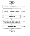
- the CPU 101 reads a tomographic image group (three-dimensional original image) to be processed from the read image data (step S101).
- step S102 the CPU 101 sets how to determine the threshold condition and the processing mode of the threshold determination process.
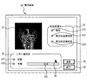
- step S102 the CPU 101 displays an operation screen 20 as shown in FIG. 4 on the display device 107, for example, and accepts various settings and input operations by the operator.
- the operation screen 20 is provided with various buttons such as an image display area 21, a processing mode selection field 22, a threshold value determination field 23, a calculation button 24, and an end button 25.
- the processing mode selection column 22 is a column for selecting a threshold determination processing method (processing mode), and includes radio buttons 221, 222, and 223 for the single mode, the isotropic proximity determination mode, and the anisotropic proximity determination mode. It is done.
- the single mode is a processing mode in which threshold determination is performed for a single pixel of interest. Similar to conventional general threshold processing, threshold processing is performed with a predetermined threshold only for the target pixel.
- the isotropic neighborhood determination mode is a mode for determining a threshold value for the target pixel and surrounding pixels using the same threshold condition.
- the anisotropic neighbor determination mode is a mode in which threshold determination is performed using different threshold conditions for a pixel on a plane including the target pixel and a pixel on another plane.
- FIG. 5 is a diagram for explaining the difference between the determination range in each mode and the threshold condition to be applied.
- the target pixel 31 is set as the determination range.
- the same threshold value t1 is used for each target pixel.
- the CPU 101 determines the target pixel 31 with the threshold value t1, and sets the target pixel 31 as a recognition pixel when the condition is satisfied.
- a 3 ⁇ 3 ⁇ 3 pixel range centered on the pixel of interest 31 is set as the determination range 33, and each pixel included in the determination range 33 Are all determined by the threshold value t1. Then, when any pixel in the determination range 33 satisfies the threshold condition (t1), the target pixel 31 is set as a recognition pixel. By including the surrounding pixels in the determination range 33, it becomes easy to extract a tissue having a fluctuation in density value such as cartilage.
- a 3 ⁇ 3 ⁇ 3 pixel range centered on the target pixel 31 is set as the determination range 33, and a plane (slice applying the threshold t1, the SLS n), applies a different threshold t2 to another plane (the slice SLS n-1, SLS n + 1), threshold determined. Then, when any of the pixels satisfies the above threshold condition, the target pixel 31 is set as a recognition pixel.
- a threshold automatic setting radio button 231 that is operated when the threshold is automatically set
- a threshold manual setting radio button 232 that is operated when the threshold is manually set
- the threshold are manually set.
- a slider 233 for changing the threshold value is provided. The slider 233 is moved by the mouse pointer 28. The setting of the threshold will be described later.
- the calculation button 24 is a button operated when starting the threshold determination process. When the calculation button 24 is pressed, the CPU 101 starts the threshold determination process using the processing mode set in the processing mode selection column 22 and the threshold condition determined in the threshold determination column 23.
- the end button 25 is a button operated when closing the operation screen 20 and ending the diagnostic image generation process.
- the CPU 101 sets a determination range 33 corresponding to the processing mode. Then, the CPU 101 executes threshold determination processing according to the selected threshold determination method and processing mode (step S103). Details of the threshold determination process will be described later.
- the CPU 101 removes or extracts the pixels recognized by the threshold determination process in step S103, and generates a diagnostic image (step S104).
- diagnostic images are typically MIP images obtained by removing bones from three-dimensional original images, three-dimensional volume rendering images, and the like.
- the CPU 101 stores the generated diagnostic image in the storage unit 103 and displays it on the display device 107 (step S105), and ends the process.
- step S103 the threshold determination process in step S103 will be described with reference to FIG.
- the threshold determination process is performed using any one of the three modes of the single mode, the isotropic proximity determination mode, and the anisotropic proximity determination mode.
- the anisotropic neighborhood determination mode is selected as the most preferable setting example for generating a diagnostic image (MIP image) from which bones and cartilage are removed in order to draw a blood vessel image of the head. It is desirable that the threshold is automatically set.
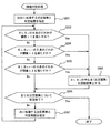
- FIG. 6 is a flowchart for explaining the flow of threshold determination processing in the anisotropic neighborhood determination mode. Further, it is assumed that the first threshold value t1 and the second threshold value t2 used for threshold determination are manually set in advance or automatically calculated. A method for automatically setting the threshold will be described later.
- the CPU 101 designates a target pixel 31 and a determination range 33 to be processed first (step S201).
- the pixel of interest 31 or the like to be processed first is not designated by the operator to be performed by the region expansion method or the like, but is determined by the CPU 101.
- the CPU 101 scans while sequentially moving the determination range 33 from the end point of the three-dimensional original image 30, and finally determines the entire three-dimensional original image 30 as a threshold value.
- CPU 101 may first one of the pixels nine slices SLS n including the pixel of interest 31 determines whether or not to satisfy a first threshold t1 (step S202). Among the pixels nine slices SLS n including the pixel of interest 31, if any of the pixels satisfies a first threshold value t1 (step S202; Yes), the center point of the slice SLS n, i.e. recognizing the pixel of interest 31 (Step S203).
- step S204 If none of the nine pixels of the plane (slice SLS n ) including the target pixel 31 satisfies the first threshold value t1 (step S202; No), another plane (slice SLS n-1 ) It is determined whether any of the nine pixels satisfies the second threshold value t2 (step S204).
- Step S204 If any of the nine pixels in the slice SLS n ⁇ 1 satisfies the second threshold value t2 (step S204; Yes), the center point of the slice SLS n , that is, the target pixel 31 is set as the recognition pixel ( Step S203).
- Step S204 No
- the second threshold value t2 among the nine pixels of another plane (slice SLS n + 1 )
- step S205 If any of the nine pixels in the slice SLS n + 1 satisfies the second threshold value t2 (step S205; Yes), the center point of the slice SLS n , that is, the target pixel 31 is set as the recognition pixel ( Step S203). If any of the nine pixels of the slice SLS n + 1 does not satisfy the second threshold value t2 (step S205; No), the target pixel 31 is not regarded as a recognition pixel, and the next determination range 33 Move on to processing.
- the CPU 101 determines whether or not the threshold determination has been completed for all the pixels of the three-dimensional original image 30 (step S206). If not (step S206; No), the determination range 30 is set to one pixel. Next or by a predetermined number of pixels (step S207).
- the CPU 101 repeatedly performs threshold determination based on the first threshold t1 and the second threshold t2 for the next determination range 33 (steps S2012 to S205). That is, in the next determination range 33, the first threshold t1 is applied to the plane including the central pixel (the target pixel 31), and the second threshold t2 is applied to another plane.
- the target pixel 31 is set as the recognition pixel when the pixel satisfies the threshold condition.
- the threshold determination process is ended.
- the above threshold determination process may be performed on the pixels used for generating the diagnostic image so that each pixel is recognized or unrecognized. In this case, threshold determination processing may not be performed for pixels that are not necessary for generating the diagnostic image.
- the threshold determination process described above is in the case of the anisotropic neighbor determination mode, but in the isotropic neighbor determination mode, the determination range 33 (for example, 3 ⁇ 3 ⁇ 3 pixels centered on the target pixel)
- the determination range 33 for example, 3 ⁇ 3 ⁇ 3 pixels centered on the target pixel
- the target pixel 31 is set as a recognition pixel. This threshold determination is repeatedly executed over the entire image while moving the determination range 33.
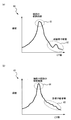
- FIG. 7 (a) is a diagram schematically showing a histogram 60 of the density value (CT value) of the CT image of the head
- FIG. 7 (b) shows the density value (CT value) of the CT image of the chest
- FIG. 6 is a diagram schematically showing a histogram 63.
- the density value histogram 60 of the head has a feature that a peak 61 indicating the soft tissue of the head and a small peak 62 corresponding to the skull and cartilage appear.
- the CPU 101 can automatically determine the threshold value of the bone region based on the position information (CT value range) of the small peak 62 corresponding to the skull and cartilage.
- the density value histogram 63 of the chest shows a peak 64 indicating the soft tissue of the chest and neck, but the CT value of the ribs and cartilage (the broken line portion of FIG. 7 (b)).
- a clear peak indicating 65) does not appear.
- the threshold value t1 is determined by the method shown in FIG.
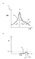
- the CPU 101 first obtains the histogram 7 of the CT image as shown in FIG. CT values at the peak (vertex 70) and peak position (vertex 70) of the obtained histogram 7 are obtained.
- CT values at the peak (vertex 70) and peak position (vertex 70) of the obtained histogram 7 are obtained.
- a distribution curve having a CT value lower than the vertex 70 is referred to as 71a
- a distribution curve having a CT value higher than the vertex 70 is referred to as 71b.
- FIG. 8 (a) shows an example of a distribution peak, but a plurality of peaks may appear.
- the peak having the highest CT value at the peak position can be used.
- the CPU 101 obtains a distribution curve 72 symmetrical to the distribution curve 71a on the side having a low CT value with the vertex 70 as a boundary position on the side having a high CT value, and sets it as the symmetrical distribution curves 71a and 72. Then, the symmetrical distribution curves 71a and 72 are subtracted from the distribution curves 71a and 71b of the original histogram 7 to obtain a distribution curve 73 after the subtraction.
- FIG. 8 (b) shows an example of the distribution curve 73 after subtraction. The horizontal axis of the distribution curve shown in FIG. 8 is the CT value, and the vertical axis is the frequency difference value. The CPU 101 calculates a threshold value based on the post-subtraction distribution curve 73.
- the difference value A1 between the vertex position CT1 and the vertex position CT1 of the post-subtraction distribution curve 73 shown in FIG. 8 (b) is obtained, and the larger CT value (CT2 ) Is set as the first threshold t1.
- N is a predetermined constant.
- the threshold value t1 may be obtained as f (expCT) using the expected value expCT of the post-subtraction distribution curve 73.
- f () represents an arbitrary function
- the expected value expCT may be calculated using the following equation, for example.
- i is an index representing the class of CT values
- CT i is a CT value corresponding to index i (each value on the horizontal axis of FIG. 8 (b))
- F i is a frequency corresponding to index i (FIG. 8 ( Each value on the vertical axis of b).
- the second threshold t2 may be obtained as in the following equation (2).
- B may be a value included in the fluctuation range (about 30 to 50) of the cartilage concentration value.
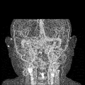
- FIG. 9 shows a threshold automatically determined by the method of FIG. 8 and a MIP image from which bone is removed by the threshold determination process in the anisotropic neighborhood determination mode.
- FIG. 10 shows a post-bone removal MIP image obtained when threshold determination processing is performed in the single mode and threshold manual setting.
- the image shown in FIG. 9 has the cartilage around the nose particularly in the center of the image removed, making it easier to observe blood vessel running. Further, the calcified region of the blood vessel (the portion where the density value of the image is high (white)) is left.
- the operator When manually setting the threshold, the operator selects the threshold manual setting radio button 232 in the threshold determination field 23 of the operation screen 20 shown in FIG. 4 and operates the threshold setting slider 233 to set the threshold. Set as appropriate.
- the CPU 101 includes a plurality of pixels (determination range 33) around the target pixel 31 included in the three-dimensional original image 30 obtained by stacking a plurality of tomographic images. ) To determine a threshold value by applying a predetermined threshold condition, and if the threshold condition is satisfied, the pixel of interest is a recognized pixel. In addition, the CPU 101 does not extend the area from the start point specified by the operator as in the conventional area expansion method, but moves the target pixel sequentially to another pixel and repeatedly executes the above threshold determination. Assume that threshold determination is performed on the entire three-dimensional original image 30.
- threshold determination process different thresholds are applied to a pixel in the same plane as the target pixel 31 and a pixel in a different plane in the determination range 33, and a threshold condition is set for any pixel in the determination range 33.
- the target pixel 31 is set as a recognition pixel (anisotropic neighborhood determination mode).
- a wide range of threshold conditions can be set, and in particular, tissues with fluctuations in concentration values such as cartilage of the head, internal tissue of bones, and ribs can be recognized with high accuracy.
- the same threshold value is applied to the target pixel and a plurality of surrounding pixels (each pixel in the determination range 33), and when it is determined that the threshold condition is satisfied in any pixel,
- the pixel 31 may be a recognition pixel (isotropic neighborhood determination mode). As a result, even if the target pixel 31 itself does not satisfy the threshold condition, it can be determined that the target pixel is a recognized pixel if the neighboring pixels satisfy the threshold condition, which is suitable for recognition of a tissue having a fluctuation in density value. is there.
- the threshold condition is preferably calculated based on a histogram of density values of the three-dimensional original image 30.
- a threshold value suitable for the feature of the density value distribution of the original image can be set, so that a more accurate result can be obtained.
- the peak position (vertex 70) of the histogram (71a, 71b) of the density value of the three-dimensional original image 30 is obtained, and data of a portion having a lower density value than the peak position (vertex 70) (
- the distribution curve 71a) is used to obtain a symmetrical distribution curve 72 with the peak position at the apex, and subtracted by subtracting the symmetrical distribution curves 71a, 72 from the original histogram distribution curves 71a, 71b.
- the post-distribution curve 73 may be obtained, and the threshold condition may be obtained based on the characteristics of the post-subtraction distribution curve 73.
- a suitable threshold can be automatically set even from a histogram having no characteristic distribution shape indicating a tissue to be recognized, such as a chest image.
- the operation screen 20 further includes a GUI (Graphical User Interface) such as a slider 233 for changing the threshold value.
- GUI Graphic User Interface
- the operation screen 20 includes, as a threshold determination processing mode, “single mode” in which threshold determination is performed for a single pixel of interest, or “isotropic determination” using the same threshold condition for a target pixel and surrounding pixels. It is desirable to provide a processing mode selection field 22 for selecting “neighboring proximity determination mode” or “anisotropic proximity determination mode” for threshold determination using different threshold conditions for a plane including the target pixel and another plane. . Thereby, it is possible to easily switch the processing mode and execute the threshold determination process.
- the operation screen 20 is provided with a threshold value determination field 23 for selecting whether the threshold condition is manually set by the operator or automatically set.
- the threshold value determination process can be executed by easily switching the threshold value setting method.
- a diagnostic image such as a three-dimensional image or a MIP image by removing or extracting the recognition pixels recognized by the threshold determination process described above from the three-dimensional original image 30.
- the present invention can be used for generating a diagnostic image.
- a suitable MIP image in which the skull and cartilage are appropriately removed can be generated for blood vessel running observation.
- the threshold value may be manually set in the anisotropic neighborhood determination mode.
- the threshold value may be automatically set in the isotropic proximity determination mode, or the threshold value may be manually set in the isotropic proximity determination mode.
- the diagnostic image (MIP image) is generated after the region is recognized (extracted / removed) by the threshold determination, but before and after the threshold determination timing and the diagnostic image generation timing.
- the relationship is not necessarily limited to this order.
- the diagnostic image may be generated by using / ignoring the recognized pixel while performing the above-described threshold determination process simultaneously with the calculation of the diagnostic image.
- the hardware configuration of the image processing apparatus 100 of the second embodiment is the same as that of the first embodiment, and therefore, redundant description is omitted, and the same components are denoted by the same reference numerals. To do.
- the CPU 101 sets a relatively wide determination range around the pixel of interest as in the determination range 33a illustrated in FIG. Then, the plane SLS n including the pixel of interest by applying a first threshold value t1, the plane SLS n-1, SLS n + 1 of a pixel adjacent to applying a second threshold value t2, 2 pixel plane next
- the third threshold value t3 is applied to SLS n-2 and SLS n + 2 .
- the CT value range of the tissue to be recognized is determined based on the density value histogram of the three-dimensional original image 30, and the threshold value t1 is set, as in the first embodiment.
- C is a value different from B.
- the value is within a range of fluctuation range of the cartilage concentration value (about 30 to 50).
- the image processing apparatus 100 sets different threshold conditions according to the distance from the target pixel in the anisotropic neighborhood determination mode, and sets any pixel in the determination range 33a. If the threshold condition is satisfied, the pixel of interest is set as a recognition pixel.
- three threshold values t1, t2, and t3 are set.However, when the determination range is wider, more threshold conditions are set and the threshold value is set according to the distance from the target pixel. The threshold condition may be changed gradually. Further, the application range of the threshold is not limited to one pixel, and a different threshold may be applied for every certain width (number of pixels).
- 1 image processing system 100 image processing device, 101 CPU, 102 main memory, 103 storage device, 104 communication I / F, 105 display memory, 106 I / F, 107 display device, 108 mouse, 109 input device, 110 network, 111 image database, 112 medical imaging device, 113 bus, 20 operation screen, 21 image display area, 22 processing mode selection column, 23 threshold determination column, 30 3D original image, 31 pixel of interest, 33, 33a judgment range (attention Pixels around the pixel), 7 density value histogram, 70 vertex of density value histogram, 71a, 71b distribution curve, 72 symmetrical distribution curve, 73 subtracted distribution curve, t1, t2, t3 threshold
Landscapes
- Engineering & Computer Science (AREA)
- Health & Medical Sciences (AREA)
- Life Sciences & Earth Sciences (AREA)
- Physics & Mathematics (AREA)
- Medical Informatics (AREA)
- Computer Vision & Pattern Recognition (AREA)
- General Physics & Mathematics (AREA)
- Theoretical Computer Science (AREA)
- General Health & Medical Sciences (AREA)
- Public Health (AREA)
- Radiology & Medical Imaging (AREA)
- Nuclear Medicine, Radiotherapy & Molecular Imaging (AREA)
- Biomedical Technology (AREA)
- Pathology (AREA)
- Surgery (AREA)
- Veterinary Medicine (AREA)
- Heart & Thoracic Surgery (AREA)
- Molecular Biology (AREA)
- High Energy & Nuclear Physics (AREA)
- Animal Behavior & Ethology (AREA)
- Biophysics (AREA)
- Optics & Photonics (AREA)
- Dentistry (AREA)
- Neurology (AREA)
- Neurosurgery (AREA)
- Physiology (AREA)
- Oral & Maxillofacial Surgery (AREA)
- Quality & Reliability (AREA)
- Epidemiology (AREA)
- Databases & Information Systems (AREA)
- Primary Health Care (AREA)
- Data Mining & Analysis (AREA)
- Apparatus For Radiation Diagnosis (AREA)
- Image Analysis (AREA)
- Image Processing (AREA)
- Ultra Sonic Daignosis Equipment (AREA)
Description
まず、図1を参照して、本発明の画像処理装置100を適用した画像処理システム1の構成について説明する。
(a)3次元原画像中に目印となる特定値を直接書き込む。
(b)3次元原画像とは別のメモリに二値画像として記録する。
図7(a)は、頭部のCT画像の濃度値(CT値)のヒストグラム60を模式的に示す図であり、図7(b)は、胸部のCT画像の濃度値(CT値)のヒストグラム63を模式的に示す図である。
図8に示す分布曲線の横軸はCT値、縦軸は頻度の差分値である。
CPU101は、減算後分布曲線73に基づいて閾値を算出する。

ここで、Bは、軟骨の濃度値の変動幅(30~50程度)に含まれる値とすればよい。
次に、図12を参照して、第2の実施の形態について説明する。
第2の実施の形態に係る画像処理装置100では、異方的近隣判定モードで判定範囲を広くとる場合に、注目画素からの距離に応じて異なる閾値条件を設定する。
ここで、Cは、Bとは異なる値とする。例えば、軟骨を認識するためには、軟骨の濃度値の変動幅(30~50程度)の範囲内の数値とする。
Claims (11)
- 画像から特定の領域を認識する処理を実行する画像処理装置であって、
前記画像に含まれる画素のうち、注目画素と周囲の複数の画素を含む判定範囲に対して所定の閾値条件を適用して閾値判定し、前記判定範囲内のいずれかの画素で前記閾値条件を満たす場合に前記注目画素を認識画素とする閾値判定部と、
前記判定範囲を順次移動して前記閾値判定を繰り返し実行する処理実行部と、
を備えることを特徴とする画像処理装置。 - 前記閾値判定部は、前記注目画素と同一平面にある画素と、別の平面にある画素とで異なる閾値条件を適用し、前記判定範囲内のいずれかの画素で前記閾値条件を満たすと判定した場合に、前記注目画素を前記認識画素とすることを特徴とする請求項1に記載の画像処理装置。
- 前記閾値条件として、前記注目画素からの距離に応じて異なる閾値を設定することを特徴とする請求項2に記載の画像処理装置。
- 前記閾値判定部は、前記判定範囲内のすべての画素に対し、同一の閾値条件を適用し、いずれかの画素で前記閾値条件を満たすと判定した場合に、前記注目画素を前記認識画素とすることを特徴とする請求項1に記載の画像処理装置。
- 前記画像の濃度値分布のヒストグラムに基づいて前記閾値条件を算出する閾値自動算出部を更に備え、
前記閾値判定部は、前記閾値自動算出部により算出された閾値条件を適用して前記閾値判定を行うことを特徴とする請求項1に記載の画像処理装置。 - 前記閾値自動算出部は、
前記画像の濃度値のヒストグラムの最大のピーク位置を求め、前記ピーク位置より濃度値の低い部分のデータを使用して前記ピーク位置を頂点として左右対称な形状の分布曲線を求め、前記ヒストグラムの分布曲線から前記左右対称な形状の分布曲線を減算することにより減算後分布曲線を求め、減算後分布曲線の特徴に基づいて前記閾値条件を求めることを特徴とする請求項5に記載の画像処理装置。 - 前記閾値条件を操作者に設定させるための閾値手動設定部を更に備え、
前記閾値判定部は、前記閾値手動設定部により設定された閾値条件を適用して前記閾値判定を行うことを特徴とする請求項1に記載の画像処理装置。 - 前記閾値判定における処理モードとして、前記注目画素単体について閾値判定を行うか、前記判定範囲に含まれる全ての画素を同一の閾値条件を用いて閾値判定するか、前記注目画素と同一平面にある画素と、別の平面にある画素とで異なる閾値条件を用いて閾値判定するか、を選択する処理モード選択部を更に備えることを特徴とする請求項1に記載の画像処理装置。
- 前記閾値条件を操作者に手動設定させるか、或いは前記閾値条件を前記画像の濃度値分布のヒストグラムに基づいて算出するかを選択する閾値設定方法選択部を更に備え、
前記閾値判定部は、前記閾値設定方法選択部により選択された方法で前記閾値条件を設定することを特徴とする請求項1に記載の画像処理装置。 - 前記閾値判定部により認識された認識画素を前記画像から除去または抽出した診断用画像を生成する診断用画像生成部を更に備えることを特徴とする請求項1に記載の画像処理装置。
- コンピュータを用いて、画像から特定の領域を認識する画像処理方法であって、
前記画像に含まれる画素のうち、注目画素と周囲の複数の画素を含む判定範囲に対して所定の閾値条件を適用して閾値判定し、前記判定範囲内のいずれかの画素で前記閾値条件を満たす場合に前記注目画素を認識画素とする閾値判定処理を、前記判定範囲を順次移動して繰り返し実行することを特徴とする画像処理方法。
Priority Applications (3)
| Application Number | Priority Date | Filing Date | Title |
|---|---|---|---|
| CN201380040163.6A CN104507392B (zh) | 2012-09-07 | 2013-08-27 | 图像处理装置及图像处理方法 |
| JP2014534308A JP6407718B2 (ja) | 2012-09-07 | 2013-08-27 | 画像処理装置及び画像処理方法 |
| US14/408,362 US9396395B2 (en) | 2012-09-07 | 2013-08-27 | Image processing apparatus and image processing method, configured to apply threshold conditions to specify target pixel |
Applications Claiming Priority (2)
| Application Number | Priority Date | Filing Date | Title |
|---|---|---|---|
| JP2012-197462 | 2012-09-07 | ||
| JP2012197462 | 2012-09-07 |
Publications (1)
| Publication Number | Publication Date |
|---|---|
| WO2014038428A1 true WO2014038428A1 (ja) | 2014-03-13 |
Family
ID=50237040
Family Applications (1)
| Application Number | Title | Priority Date | Filing Date |
|---|---|---|---|
| PCT/JP2013/072802 Ceased WO2014038428A1 (ja) | 2012-09-07 | 2013-08-27 | 画像処理装置及び画像処理方法 |
Country Status (4)
| Country | Link |
|---|---|
| US (1) | US9396395B2 (ja) |
| JP (1) | JP6407718B2 (ja) |
| CN (1) | CN104507392B (ja) |
| WO (1) | WO2014038428A1 (ja) |
Cited By (2)
| Publication number | Priority date | Publication date | Assignee | Title |
|---|---|---|---|---|
| WO2017179255A1 (ja) * | 2016-04-13 | 2017-10-19 | 日本メジフィジックス株式会社 | Ct画像中の骨領域の自動推定方法、装置、およびコンピュータプログラム |
| CN114092932A (zh) * | 2021-09-13 | 2022-02-25 | 网易(杭州)网络有限公司 | 倒角面的识别方法、装置、电子设备及存储介质 |
Families Citing this family (6)
| Publication number | Priority date | Publication date | Assignee | Title |
|---|---|---|---|---|
| CN118236208A (zh) * | 2013-10-15 | 2024-06-25 | 穆罕默德·拉什万·马赫福兹 | 骨骼重建和骨外科植入物 |
| CN105096332B (zh) * | 2015-08-25 | 2019-06-28 | 上海联影医疗科技有限公司 | 医学图像分割方法和装置 |
| GB2547399B (en) | 2014-12-02 | 2018-05-02 | Shanghai United Imaging Healthcare Co Ltd | A method and system for image processing |
| JP2018126389A (ja) * | 2017-02-09 | 2018-08-16 | キヤノン株式会社 | 情報処理装置、情報処理方法、およびプログラム |
| EP3633603B1 (en) * | 2017-06-30 | 2025-05-07 | Shanghai United Imaging Healthcare Co., Ltd. | Tissue density analysis method and system |
| US10470825B2 (en) * | 2017-08-16 | 2019-11-12 | Synaptive Medical (Barbados) Inc. | Method, system and apparatus for surface rendering using medical imaging data |
Citations (9)
| Publication number | Priority date | Publication date | Assignee | Title |
|---|---|---|---|---|
| JP2004201730A (ja) * | 2002-12-24 | 2004-07-22 | Hitachi Ltd | 複数方向の投影映像を用いた3次元形状の生成方法 |
| JP2005073817A (ja) * | 2003-08-29 | 2005-03-24 | Hitachi Medical Corp | 医用画像表示装置 |
| JP2005316583A (ja) * | 2004-04-27 | 2005-11-10 | Konica Minolta Photo Imaging Inc | 画像処理方法、画像処理装置及び画像処理プログラム |
| WO2007135913A1 (ja) * | 2006-05-19 | 2007-11-29 | Hitachi Medical Corporation | 医用画像表示装置及びプログラム |
| JP2007534352A (ja) * | 2003-07-31 | 2007-11-29 | シーメンス メディカル ソリューションズ ユーエスエー インコーポレイテッド | すりガラス様小結節(ggn)セグメンテーションを行うためのシステムおよび方法 |
| JP2007312838A (ja) * | 2006-05-23 | 2007-12-06 | Konica Minolta Medical & Graphic Inc | モデリング装置、モデリング方法およびプログラム |
| JP2007537812A (ja) * | 2004-05-18 | 2007-12-27 | メディックサイト ピーエルシー | 結節境界の検出方法 |
| JP2009226043A (ja) * | 2008-03-24 | 2009-10-08 | Gifu Univ | 医用画像処理装置及び異常陰影検出方法 |
| JP2011514190A (ja) * | 2008-02-29 | 2011-05-06 | エージェンシー フォー サイエンス,テクノロジー アンド リサーチ | 画像内の解剖学的構造のセグメンテーションおよびモデリングのための方法およびシステム |
Family Cites Families (9)
| Publication number | Priority date | Publication date | Assignee | Title |
|---|---|---|---|---|
| US4731863A (en) * | 1986-04-07 | 1988-03-15 | Eastman Kodak Company | Digital image processing method employing histogram peak detection |
| JP2768786B2 (ja) * | 1990-02-20 | 1998-06-25 | キヤノン株式会社 | 画像読み取り装置 |
| US6678393B1 (en) * | 1997-12-23 | 2004-01-13 | Intel Corporation | Image selection based on image content |
| US20020131643A1 (en) * | 2001-03-13 | 2002-09-19 | Fels Sol Sidney | Local positioning system |
| US7209581B2 (en) | 2003-07-31 | 2007-04-24 | Siemens Medical Solutions Usa, Inc. | System and method for ground glass nodule (GGN) segmentation |
| US7653225B2 (en) | 2003-09-17 | 2010-01-26 | Siemens Corporation | Method and system for ground glass nodule (GGN) segmentation with shape analysis |
| JP2007028362A (ja) * | 2005-07-20 | 2007-02-01 | Seiko Epson Corp | 背景画像と目的画像が混在する画像データを処理するための装置及び方法 |
| WO2009145076A1 (ja) * | 2008-05-28 | 2009-12-03 | 株式会社 日立メディコ | 画像処理装置、画像処理方法、及び画像処理プログラム |
| JP2010187756A (ja) * | 2009-02-16 | 2010-09-02 | Olympus Corp | 画像処理装置、画像処理方法および画像処理プログラム |
-
2013
- 2013-08-27 US US14/408,362 patent/US9396395B2/en active Active
- 2013-08-27 JP JP2014534308A patent/JP6407718B2/ja active Active
- 2013-08-27 CN CN201380040163.6A patent/CN104507392B/zh not_active Expired - Fee Related
- 2013-08-27 WO PCT/JP2013/072802 patent/WO2014038428A1/ja not_active Ceased
Patent Citations (9)
| Publication number | Priority date | Publication date | Assignee | Title |
|---|---|---|---|---|
| JP2004201730A (ja) * | 2002-12-24 | 2004-07-22 | Hitachi Ltd | 複数方向の投影映像を用いた3次元形状の生成方法 |
| JP2007534352A (ja) * | 2003-07-31 | 2007-11-29 | シーメンス メディカル ソリューションズ ユーエスエー インコーポレイテッド | すりガラス様小結節(ggn)セグメンテーションを行うためのシステムおよび方法 |
| JP2005073817A (ja) * | 2003-08-29 | 2005-03-24 | Hitachi Medical Corp | 医用画像表示装置 |
| JP2005316583A (ja) * | 2004-04-27 | 2005-11-10 | Konica Minolta Photo Imaging Inc | 画像処理方法、画像処理装置及び画像処理プログラム |
| JP2007537812A (ja) * | 2004-05-18 | 2007-12-27 | メディックサイト ピーエルシー | 結節境界の検出方法 |
| WO2007135913A1 (ja) * | 2006-05-19 | 2007-11-29 | Hitachi Medical Corporation | 医用画像表示装置及びプログラム |
| JP2007312838A (ja) * | 2006-05-23 | 2007-12-06 | Konica Minolta Medical & Graphic Inc | モデリング装置、モデリング方法およびプログラム |
| JP2011514190A (ja) * | 2008-02-29 | 2011-05-06 | エージェンシー フォー サイエンス,テクノロジー アンド リサーチ | 画像内の解剖学的構造のセグメンテーションおよびモデリングのための方法およびシステム |
| JP2009226043A (ja) * | 2008-03-24 | 2009-10-08 | Gifu Univ | 医用画像処理装置及び異常陰影検出方法 |
Cited By (3)
| Publication number | Priority date | Publication date | Assignee | Title |
|---|---|---|---|---|
| WO2017179255A1 (ja) * | 2016-04-13 | 2017-10-19 | 日本メジフィジックス株式会社 | Ct画像中の骨領域の自動推定方法、装置、およびコンピュータプログラム |
| JPWO2017179255A1 (ja) * | 2016-04-13 | 2019-02-21 | 日本メジフィジックス株式会社 | Ct画像中の骨領域の自動推定方法、装置、およびコンピュータプログラム |
| CN114092932A (zh) * | 2021-09-13 | 2022-02-25 | 网易(杭州)网络有限公司 | 倒角面的识别方法、装置、电子设备及存储介质 |
Also Published As
| Publication number | Publication date |
|---|---|
| JPWO2014038428A1 (ja) | 2016-08-08 |
| CN104507392B (zh) | 2017-03-08 |
| CN104507392A (zh) | 2015-04-08 |
| JP6407718B2 (ja) | 2018-10-17 |
| US20150235085A1 (en) | 2015-08-20 |
| US9396395B2 (en) | 2016-07-19 |
Similar Documents
| Publication | Publication Date | Title |
|---|---|---|
| JP6407718B2 (ja) | 画像処理装置及び画像処理方法 | |
| JP4931027B2 (ja) | 医用画像診断支援装置および方法、並びにプログラム | |
| US9466117B2 (en) | Segmentation highlighter | |
| US9959622B2 (en) | Method and apparatus for supporting diagnosis of region of interest by providing comparison image | |
| JP5943353B2 (ja) | 画像処理装置及び画像処理方法 | |
| JP2015514447A (ja) | マルチモーダル画像統合におけるレジストレーション精度を改善するインテリジェントなランドマーク選択 | |
| CN111445449A (zh) | 感兴趣区域的分类方法、装置、计算机设备和存储介质 | |
| US8718344B2 (en) | Image processing apparatus and medical image diagnosis apparatus | |
| JP5442542B2 (ja) | 病理診断支援装置、病理診断支援方法、病理診断支援のための制御プログラムおよび該制御プログラムを記録した記録媒体 | |
| CN112043378A (zh) | 对人进行导航支持以关于切除部分进行导航的方法和系统 | |
| CN107507212A (zh) | 数字脑可视化方法、装置、计算设备及存储介质 | |
| JP4373682B2 (ja) | 関心組織領域抽出方法、関心組織領域抽出プログラム及び画像処理装置 | |
| JP6687395B2 (ja) | 医用画像処理装置、医用画像処理方法及び医用イメージング装置 | |
| JP6571687B2 (ja) | 画像処理装置及び画像処理方法 | |
| JP2014221201A (ja) | 撮像制御装置、医用画像診断装置及び撮像制御方法 | |
| JP5486616B2 (ja) | 医用画像診断支援装置およびその作動方法、並びにプログラム | |
| US20170018079A1 (en) | Image processing device, method, and recording medium having stored therein program | |
| WO2016208016A1 (ja) | 画像処理装置、画像処理方法、及び画像処理プログラム | |
| WO2013121679A1 (ja) | 領域抽出処理システム | |
| JP2009022307A (ja) | 医用画像表示装置及びそのプログラム | |
| JP6068883B2 (ja) | 画像処理装置及び領域抽出方法 | |
| WO2010035520A1 (ja) | 医用画像処理装置及びプログラム |
Legal Events
| Date | Code | Title | Description |
|---|---|---|---|
| 121 | Ep: the epo has been informed by wipo that ep was designated in this application |
Ref document number: 13835125 Country of ref document: EP Kind code of ref document: A1 |
|
| WWE | Wipo information: entry into national phase |
Ref document number: 14408362 Country of ref document: US |
|
| ENP | Entry into the national phase |
Ref document number: 2014534308 Country of ref document: JP Kind code of ref document: A |
|
| NENP | Non-entry into the national phase |
Ref country code: DE |
|
| 122 | Ep: pct application non-entry in european phase |
Ref document number: 13835125 Country of ref document: EP Kind code of ref document: A1 |