WO2014038102A1 - スピーカ - Google Patents
スピーカ Download PDFInfo
- Publication number
- WO2014038102A1 WO2014038102A1 PCT/JP2012/084015 JP2012084015W WO2014038102A1 WO 2014038102 A1 WO2014038102 A1 WO 2014038102A1 JP 2012084015 W JP2012084015 W JP 2012084015W WO 2014038102 A1 WO2014038102 A1 WO 2014038102A1
- Authority
- WO
- WIPO (PCT)
- Prior art keywords
- bobbin
- coil
- speaker
- wound
- cavity
- Prior art date
- Legal status (The legal status is an assumption and is not a legal conclusion. Google has not performed a legal analysis and makes no representation as to the accuracy of the status listed.)
- Ceased
Links
Images

Classifications
-
- H—ELECTRICITY
- H04—ELECTRIC COMMUNICATION TECHNIQUE
- H04R—LOUDSPEAKERS, MICROPHONES, GRAMOPHONE PICK-UPS OR LIKE ACOUSTIC ELECTROMECHANICAL TRANSDUCERS; DEAF-AID SETS; PUBLIC ADDRESS SYSTEMS
- H04R9/00—Transducers of moving-coil, moving-strip, or moving-wire type
- H04R9/02—Details
- H04R9/04—Construction, mounting, or centering of coil
- H04R9/046—Construction
-
- H—ELECTRICITY
- H04—ELECTRIC COMMUNICATION TECHNIQUE
- H04R—LOUDSPEAKERS, MICROPHONES, GRAMOPHONE PICK-UPS OR LIKE ACOUSTIC ELECTROMECHANICAL TRANSDUCERS; DEAF-AID SETS; PUBLIC ADDRESS SYSTEMS
- H04R7/00—Diaphragms for electromechanical transducers; Cones
- H04R7/02—Diaphragms for electromechanical transducers; Cones characterised by the construction
-
- H—ELECTRICITY
- H04—ELECTRIC COMMUNICATION TECHNIQUE
- H04R—LOUDSPEAKERS, MICROPHONES, GRAMOPHONE PICK-UPS OR LIKE ACOUSTIC ELECTROMECHANICAL TRANSDUCERS; DEAF-AID SETS; PUBLIC ADDRESS SYSTEMS
- H04R9/00—Transducers of moving-coil, moving-strip, or moving-wire type
- H04R9/02—Details
Definitions
- This invention relates to a technique for increasing the original sound reproduction ability of a speaker.
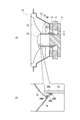
- FIG. 4A is a diagram illustrating an example of the structure of a conventional sealed speaker 70.
- an annular magnet 73 and an annular plate 74 surrounding the center pole 72 of the plate 71 are disposed on the back plate 71.
- a neck portion of the frame 75 is fixed to the front surface of the annular plate 74.
- a portion of the voice coil bobbin 76 around which the coil 77 is wound is accommodated in the magnetic gap GP1 which is a gap between the inner peripheral surface of the annular plate 74 and the outer peripheral surface of the center pole 72.
- a neck portion of the diaphragm 78 is joined to a portion of the outer peripheral surface of the boil coil bobbin 76 that is slightly away from the tip.
- the periphery of the cap 79 is joined slightly outside the neck portion on the surface (sound emitting surface) of the diaphragm 78.
- the diaphragm 78 and the voice coil bobbin 76 are covered with the inner peripheral surface of the frame 75, and a damper 80 is installed between the outer peripheral surface of the bobbin 76 and the inner peripheral surface of the frame 75.
- the configuration of this type of speaker is disclosed in Patent Document 1, for example.
- the joint portion of the diaphragm 78 and the bobbin 76 in this type of speaker has a configuration in which the tip of the neck portion of the diaphragm 78 is in line contact with the outer peripheral surface of the bobbin 76.
- the joining portion between the cap 79 and the diaphragm 78 has a configuration in which the periphery of the cap 79 is in line contact with the surface of the diaphragm 78.
- the conventional speaker of this type has a problem that the usage fee of the adhesive, which is a substance that causes sound turbidity, increases, and it is difficult to enhance the ability to reproduce the original sound.
- the present invention has been made in view of such problems, and an object thereof is to provide a speaker having a high original sound reproduction capability.
- the present invention includes an enclosure having an opening and a cavity communicating with the opening, a vibrating portion supported on the inner periphery of the opening, and a magnetic gap.
- a magnetic circuit supported on the cavity side so as to face the part, and a coil is wound around the outer peripheral surface of one end, and the end on which the coil is wound is accommodated in the magnetic gap and
- the speaker is characterized in that the expanded portion is bonded to the vibrating portion.
- the end of the bobbin on the side opposite to the side where the coil is wound spreads outward in the radial direction of the bobbin, and the expanded part is bonded to the diaphragm.
- the adhesive is thinly applied only to a portion sandwiched between a portion of the vibration portion that extends outward in the radial direction of the bobbin, sufficient bonding strength can be ensured. Therefore, according to the present invention, the usage fee of the adhesive can be reduced compared to a speaker having a configuration in which the tip of the neck portion of the diaphragm is in line contact with the outer peripheral surface of the bobbin.
- the present invention it is possible to provide a loudspeaker having a higher ability to reproduce the original sound than a loudspeaker having a configuration in which the tip of the neck portion of the diaphragm is in line contact with the outer peripheral surface of the bobbin.
- FIG. 2 is a cross-sectional view taken along line A-A ′ in FIG. 1 and a part of the cross-sectional view enlarged. It is the side view and perspective view of the bobbin in the speaker of FIG. It is sectional drawing of the conventional speaker, and the figure which expanded a part of this sectional view.
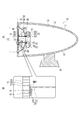
- FIG. 1 is a front view of a speaker 10 according to an embodiment of the present invention.
- FIG. 2A is a cross-sectional view taken along the line A-A ′ of FIG.
- An enclosure 11 of the speaker 10 has an opening 12 and a cavity 13 communicating with the opening 12.
- the enclosure 11 has a substantially egg shape.
- the thickness of the outer shell wall surrounding the cavity 13 in the enclosure 11 is uniform.
- the inner wall surface 14 of the enclosure 11 is curved so that the cavity 13 is substantially oval.
- Legs 16 are fixed to the outer wall surface 15 of the enclosure 11.
- the opening 12 of the enclosure 11 has a perfect circle shape.
- a speaker unit 20 is fitted in the opening 12.
- the speaker unit 20 is a device that radiates a given electric signal as a sound wave that is an air dense wave.
- the speaker unit 20 includes a vibration unit 21, a frame 22 that covers the vibration unit 21 from the cavity 13 side, a magnetic circuit 23 provided at an end of the frame 22 opposite to the vibration unit 21, and vibration in the frame 22. And a bobbin 24 interposed between the portion 21 and the magnetic circuit 23.
- the vibrating section 21 includes a honeycomb core 25 having a hollow honeycomb structure and two aluminum films 26 and 27 covering the honeycomb core 25 from both sides.
- the films 26 and 27 of the vibration part 21 have a perfect circle shape having a slightly smaller diameter than the opening 12.
- the outer periphery of the film 26 of the vibration part 21 is supported on the inner periphery of the opening 12 via an edge part 49.
- the frame 22 has a substantially conical shape.
- the frame 22 has a perfect circular opening on one side and the other side in the axial direction.
- the frame 22 is fixed to the inner peripheral portion of the opening 12 of the enclosure 11 with the larger diameter of the two openings facing the vibrating portion 21.
- the magnetic circuit 23 is a member in which the yoke 28, the permanent magnet 29, and the plate 30 are integrated.
- the magnetic circuit 23 is supported on the cavity 13 side of the part 21 so that the magnetic gap GP2 faces the vibration part 21.
- the yoke 28 of the magnetic circuit 23 includes a disk portion 31 and a center pole portion 32 that shares a central axis with the portion 31.
- a cross section (a cross section shown in FIG. 2A) obtained by cutting a plane passing through the central axis of the disk portion 31 and the center pole portion 32 in the yoke 28 is a convex shape.
- the permanent magnet 29 has an annular shape.
- the permanent magnet 29 has an N pole on one end face (for example, the end face 42) of the end faces 42 and 43 opposed in the thickness direction, and an S pole on the other end face (for example, the end face 43).
- the inner peripheral diameter of the hole in the permanent magnet 29 is larger than the outer peripheral diameter of the center pole portion 32.
- the end surface 42 of the permanent magnet 29 is fixed to the end surface 41 on the side where the center pole portion 32 is present in the disk portion 31.
- the center pole portion 32 protrudes toward the end face 43 of the permanent magnet 29 through the approximate center of the hole in the permanent magnet 29.
- the plate 30 has an annular shape that is thinner than the permanent magnet 29.
- the inner diameter of the hole in the plate 30 is larger than the outer diameter of the center pole portion 32 and smaller than the inner diameter of the hole in the permanent magnet 29.
- One end face 44 of the plate 30 is fixed to the end face 43 of the permanent magnet 29.
- the other end face 45 of the plate 30 is fixed to an end face 46 surrounding the smaller diameter opening in the frame 22.
- the inner peripheral surface of the hole in the plate 30 surrounds the outer peripheral surface of the center pole portion 32 protruding from the permanent magnet 29.
- a gap between the inner peripheral surface of the plate 30 and the outer peripheral surface of the center pole portion 32 forms a magnetic gap GP2.
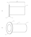
- the bobbin 24 has a coil 48 wound around the outer peripheral surface of one end of a cylindrical tube portion 51 (FIG. 2B), and an end opposite to the side where the coil 48 is wound is a flange portion 52. As shown in FIG. 2 (B), the bobbin 24 is expanded outward in the radial direction. A damper 47 is installed between the outer peripheral surface of the cylindrical portion 51 of the bobbin 24 and the inner peripheral surface of the frame 22.
- FIG. 3A is an enlarged view of the bobbin 24 of FIG.
- FIG. 3B is a perspective view of FIG.
- the flange portion 52 of the bobbin 24 has an annular shape.
- the dimension of the flange part 52 in the radial direction (the dimension of the width in the direction from the center of the flange part 52 toward the outer peripheral surface of the flange part 52) is smaller than the diameter of the cylinder part 51. Further, the end surfaces 61 and 62 facing the thickness direction of the flange portion 52 are orthogonal to the extending direction of the tube portion 51.
- the end of the bobbin 24 around which the coil 48 is wound is housed in the magnetic gap GP2 of the magnetic circuit 23.
- the end surface 62 of the flange portion 52 which is the end of the bobbin 24 opposite to the side where the coil 48 is wound, is oscillated by the soft adhesive BND. 21 is adhered to the film 27.
- the end surface 62 of the flange portion 52 of the bobbin 24 and the film 27 of the vibration portion 21 face each other in parallel.
- a soft adhesive BND is applied between the end face 62 of the flange portion 52 and the film 27 of the vibration portion 21 with a substantially uniform thickness.
- the magnetic lines of force generated by the permanent magnet 29 make a round of the yoke 28 and the plate 30, and the magnetic lines cross the magnetic gap GP2. For this reason, when a current of a sound signal is passed through the coil 48 of the bobbin 24, a driving force in a direction orthogonal to the extending direction of the coil 48 is given to the bobbin 24, and the vibration part in which the end of the bobbin 24 is bonded. 21 vibrates. An air density wave generated by the vibration of the vibrating portion 21 is radiated forward as a sound wave.
- the end of the bobbin 24 opposite to the side around which the coil 48 is wound is expanded outward in the radial direction of the bobbin 24, and the flange portion 52 which is the expanded portion. Is bonded to the vibration part 21. For this reason, if the adhesive BND is thinly applied only to a portion sandwiched between the vibration portion 21 and the flange portion 52 of the bobbin 24, sufficient bonding strength can be ensured.
- the usage fee of the adhesive can be reduced as compared with a speaker having a configuration in which the tip of the neck portion of the vibrating portion is in line contact with the outer peripheral surface of the bobbin. Therefore, according to the present embodiment, it is possible to provide a loudspeaker having a higher ability to reproduce the original sound than a loudspeaker having a configuration in which the tip of the neck portion of the vibrating portion is in line contact with the outer peripheral surface of the bobbin.
- the vibration section 21 includes a honeycomb core 25 having a hollow honeycomb structure and two aluminum films 26 and 27 sandwiching the honeycomb core 25 from both sides. For this reason, the reproduction capability of a high sound range can be made higher than the speaker which has a vibration part with another structure.
- the portion of the end of the bobbin 24 that extends outward in the radial direction of the bobbin 24 forms an annular flange 52, and the flange 52 and the film 27 face each other in parallel. is doing. For this reason, it becomes easy to make the thickness of the adhesive BND applied between the flange portion 52 and the film 27 uniform. Therefore, according to the present embodiment, the unevenness of the adhesive BND at the joint portion between the bobbin 24 and the vibration part 21 is reduced, and the bobbin 24 is more difficult to peel off.
- the inner wall surface 14 of the enclosure 11 is curved so that the cavity 13 forms a substantially egg shape. Therefore, according to this embodiment, the sound wave radiated from the vibrating portion 21 to the cavity 13 does not reciprocate along the inner wall surface 14. Therefore, according to the present embodiment, it is possible to suppress the occurrence of standing waves in the cavity 13.
- the enclosure 11 has a substantially egg shape.
- the enclosure 11 may be rectangular.
- the vibration part 21 is composed of the honeycomb core 25 and the films 26 and 27. However, you may replace this vibration part 21 with what consists of cone paper and a cap. In this case, the direction of diffusion of the flange 52, which is the end of the bobbin 24 (the end opposite to the side where the coil 48 is wound), should be the same as the angle of the tapered surface forming the outer periphery of the cone paper. .
Landscapes
- Engineering & Computer Science (AREA)
- Physics & Mathematics (AREA)
- Acoustics & Sound (AREA)
- Signal Processing (AREA)
- Multimedia (AREA)
- Audible-Bandwidth Dynamoelectric Transducers Other Than Pickups (AREA)
- Diaphragms For Electromechanical Transducers (AREA)
- Details Of Audible-Bandwidth Transducers (AREA)
Priority Applications (1)
| Application Number | Priority Date | Filing Date | Title |
|---|---|---|---|
| CN201290000171.9U CN203596912U (zh) | 2012-09-07 | 2012-12-28 | 扬声器 |
Applications Claiming Priority (2)
| Application Number | Priority Date | Filing Date | Title |
|---|---|---|---|
| JP2012-197934 | 2012-09-07 | ||
| JP2012197934 | 2012-09-07 |
Publications (1)
| Publication Number | Publication Date |
|---|---|
| WO2014038102A1 true WO2014038102A1 (ja) | 2014-03-13 |
Family
ID=50236743
Family Applications (1)
| Application Number | Title | Priority Date | Filing Date |
|---|---|---|---|
| PCT/JP2012/084015 Ceased WO2014038102A1 (ja) | 2012-09-07 | 2012-12-28 | スピーカ |
Country Status (3)
| Country | Link |
|---|---|
| JP (2) | JP5731602B2 (enExample) |
| CN (1) | CN203596912U (enExample) |
| WO (1) | WO2014038102A1 (enExample) |
Cited By (1)
| Publication number | Priority date | Publication date | Assignee | Title |
|---|---|---|---|---|
| US9532132B2 (en) | 2013-09-09 | 2016-12-27 | Shinichirou NAKAISHI | Hearing-impaired person assistance speaker |
Families Citing this family (3)
| Publication number | Priority date | Publication date | Assignee | Title |
|---|---|---|---|---|
| JP6282172B2 (ja) * | 2014-05-19 | 2018-02-21 | シャープ株式会社 | スピーカボックスおよびテレビ受信装置 |
| CN107079225B (zh) * | 2014-12-02 | 2019-12-10 | 索尼公司 | 扬声器装置 |
| JP7091900B2 (ja) * | 2018-07-17 | 2022-06-28 | ヤマハ株式会社 | 電気音響変換装置 |
Citations (3)
| Publication number | Priority date | Publication date | Assignee | Title |
|---|---|---|---|---|
| JPS6068796U (ja) * | 1983-10-19 | 1985-05-15 | ソニー株式会社 | 平板スピ−カ |
| JP2003304585A (ja) * | 2002-04-12 | 2003-10-24 | Kenwood Corp | スピーカシステム |
| JP2005005815A (ja) * | 2003-06-09 | 2005-01-06 | Fujitsu Ten Ltd | 支持装置 |
Family Cites Families (8)
| Publication number | Priority date | Publication date | Assignee | Title |
|---|---|---|---|---|
| JPS56147687U (enExample) * | 1980-04-04 | 1981-11-06 | ||
| JPS57101494A (en) * | 1980-12-16 | 1982-06-24 | Matsushita Electric Ind Co Ltd | Manufacture for core member of vibration diaphragm for speaker |
| JPS59125195U (ja) * | 1983-02-10 | 1984-08-23 | ソニー株式会社 | 平板スピ−カ |
| JP3484143B2 (ja) * | 1999-12-02 | 2004-01-06 | 株式会社タイムドメイン | スピーカ装置 |
| JP2002247675A (ja) * | 2001-02-14 | 2002-08-30 | Time Domain:Kk | スピーカシステム |
| JP2008137514A (ja) * | 2006-12-01 | 2008-06-19 | Kenwood Corp | 車載オーディオシステムおよび車載用マイク付きツイータスピーカユニット |
| JPWO2009113319A1 (ja) * | 2008-03-13 | 2011-07-21 | タカノ株式会社 | スピーカ組み込み椅子 |
| GB0811015D0 (en) * | 2008-06-17 | 2008-07-23 | Deben Acoustics | Improved acoustic device |
-
2012
- 2012-12-28 CN CN201290000171.9U patent/CN203596912U/zh not_active Expired - Lifetime
- 2012-12-28 WO PCT/JP2012/084015 patent/WO2014038102A1/ja not_active Ceased
-
2013
- 2013-09-09 JP JP2013185848A patent/JP5731602B2/ja active Active
-
2015
- 2015-04-06 JP JP2015077756A patent/JP6250582B2/ja active Active
Patent Citations (3)
| Publication number | Priority date | Publication date | Assignee | Title |
|---|---|---|---|---|
| JPS6068796U (ja) * | 1983-10-19 | 1985-05-15 | ソニー株式会社 | 平板スピ−カ |
| JP2003304585A (ja) * | 2002-04-12 | 2003-10-24 | Kenwood Corp | スピーカシステム |
| JP2005005815A (ja) * | 2003-06-09 | 2005-01-06 | Fujitsu Ten Ltd | 支持装置 |
Cited By (1)
| Publication number | Priority date | Publication date | Assignee | Title |
|---|---|---|---|---|
| US9532132B2 (en) | 2013-09-09 | 2016-12-27 | Shinichirou NAKAISHI | Hearing-impaired person assistance speaker |
Also Published As
| Publication number | Publication date |
|---|---|
| JP6250582B2 (ja) | 2017-12-20 |
| CN203596912U (zh) | 2014-05-14 |
| HK1222279A1 (zh) | 2017-06-23 |
| JP2014068342A (ja) | 2014-04-17 |
| JP5731602B2 (ja) | 2015-06-10 |
| JP2015146632A (ja) | 2015-08-13 |
Similar Documents
| Publication | Publication Date | Title |
|---|---|---|
| US10299035B2 (en) | Acoustic lens system for loudspeakers | |
| JP5700704B2 (ja) | スピーカ装置 | |
| US9756426B2 (en) | Loudspeaker | |
| WO2010050056A1 (ja) | スピーカ用連結部材及びスピーカ | |
| WO2014038102A1 (ja) | スピーカ | |
| JP2007235232A (ja) | スピーカ | |
| WO2019077925A1 (ja) | スピーカ、および、振動板ユニット | |
| WO2015033970A1 (ja) | 難聴者支援スピーカ | |
| JP5825522B2 (ja) | スピーカ装置 | |
| JP6482004B2 (ja) | スピーカ | |
| JP2010034988A (ja) | スピーカ装置 | |
| JP5327616B2 (ja) | スピーカユニット | |
| JP6993459B2 (ja) | 電気音響ドライバ | |
| JP2016052076A (ja) | スピーカ用平面振動板と、それを用いたスピーカ | |
| JP2012044352A (ja) | スピーカー | |
| JPH0349515Y2 (enExample) | ||
| JP2022150705A (ja) | スピーカー装置 | |
| JP4417817B2 (ja) | スピーカ | |
| JP2015070600A (ja) | コンデンサヘッドホンユニットおよびコンデンサヘッドホンの固定極組立体の製造方法 | |
| JP7454459B2 (ja) | スピーカ | |
| JP2009100292A (ja) | スピーカ | |
| JP2008167247A (ja) | ボイスコイルモータおよびこれを用いたスピーカ | |
| JP2008271025A (ja) | スピーカ用エッジおよびスピーカ装置 | |
| JP2010034989A (ja) | スピーカ装置 | |
| JP6680832B2 (ja) | スピーカ装置 |
Legal Events
| Date | Code | Title | Description |
|---|---|---|---|
| WWE | Wipo information: entry into national phase |
Ref document number: 201290000171.9 Country of ref document: CN |
|
| 121 | Ep: the epo has been informed by wipo that ep was designated in this application |
Ref document number: 12884211 Country of ref document: EP Kind code of ref document: A1 |
|
| NENP | Non-entry into the national phase |
Ref country code: DE |
|
| 122 | Ep: pct application non-entry in european phase |
Ref document number: 12884211 Country of ref document: EP Kind code of ref document: A1 |