WO2014038102A1 - Speaker - Google Patents
Speaker Download PDFInfo
- Publication number
- WO2014038102A1 WO2014038102A1 PCT/JP2012/084015 JP2012084015W WO2014038102A1 WO 2014038102 A1 WO2014038102 A1 WO 2014038102A1 JP 2012084015 W JP2012084015 W JP 2012084015W WO 2014038102 A1 WO2014038102 A1 WO 2014038102A1
- Authority
- WO
- WIPO (PCT)
- Prior art keywords
- bobbin
- coil
- speaker
- vibrating
- wound
- Prior art date
Links
Images

Classifications
-
- H—ELECTRICITY
- H04—ELECTRIC COMMUNICATION TECHNIQUE
- H04R—LOUDSPEAKERS, MICROPHONES, GRAMOPHONE PICK-UPS OR LIKE ACOUSTIC ELECTROMECHANICAL TRANSDUCERS; DEAF-AID SETS; PUBLIC ADDRESS SYSTEMS
- H04R9/00—Transducers of moving-coil, moving-strip, or moving-wire type
- H04R9/02—Details
- H04R9/04—Construction, mounting, or centering of coil
- H04R9/046—Construction
-
- H—ELECTRICITY
- H04—ELECTRIC COMMUNICATION TECHNIQUE
- H04R—LOUDSPEAKERS, MICROPHONES, GRAMOPHONE PICK-UPS OR LIKE ACOUSTIC ELECTROMECHANICAL TRANSDUCERS; DEAF-AID SETS; PUBLIC ADDRESS SYSTEMS
- H04R7/00—Diaphragms for electromechanical transducers; Cones
- H04R7/02—Diaphragms for electromechanical transducers; Cones characterised by the construction
-
- H—ELECTRICITY
- H04—ELECTRIC COMMUNICATION TECHNIQUE
- H04R—LOUDSPEAKERS, MICROPHONES, GRAMOPHONE PICK-UPS OR LIKE ACOUSTIC ELECTROMECHANICAL TRANSDUCERS; DEAF-AID SETS; PUBLIC ADDRESS SYSTEMS
- H04R9/00—Transducers of moving-coil, moving-strip, or moving-wire type
- H04R9/02—Details
Definitions
- This invention relates to a technique for increasing the original sound reproduction ability of a speaker.
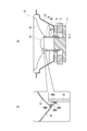
- FIG. 4A is a diagram illustrating an example of the structure of a conventional sealed speaker 70.
- an annular magnet 73 and an annular plate 74 surrounding the center pole 72 of the plate 71 are disposed on the back plate 71.
- a neck portion of the frame 75 is fixed to the front surface of the annular plate 74.
- a portion of the voice coil bobbin 76 around which the coil 77 is wound is accommodated in the magnetic gap GP1 which is a gap between the inner peripheral surface of the annular plate 74 and the outer peripheral surface of the center pole 72.
- a neck portion of the diaphragm 78 is joined to a portion of the outer peripheral surface of the boil coil bobbin 76 that is slightly away from the tip.
- the periphery of the cap 79 is joined slightly outside the neck portion on the surface (sound emitting surface) of the diaphragm 78.
- the diaphragm 78 and the voice coil bobbin 76 are covered with the inner peripheral surface of the frame 75, and a damper 80 is installed between the outer peripheral surface of the bobbin 76 and the inner peripheral surface of the frame 75.
- the configuration of this type of speaker is disclosed in Patent Document 1, for example.
- the joint portion of the diaphragm 78 and the bobbin 76 in this type of speaker has a configuration in which the tip of the neck portion of the diaphragm 78 is in line contact with the outer peripheral surface of the bobbin 76.
- the joining portion between the cap 79 and the diaphragm 78 has a configuration in which the periphery of the cap 79 is in line contact with the surface of the diaphragm 78.
- the conventional speaker of this type has a problem that the usage fee of the adhesive, which is a substance that causes sound turbidity, increases, and it is difficult to enhance the ability to reproduce the original sound.
- the present invention has been made in view of such problems, and an object thereof is to provide a speaker having a high original sound reproduction capability.
- the present invention includes an enclosure having an opening and a cavity communicating with the opening, a vibrating portion supported on the inner periphery of the opening, and a magnetic gap.
- a magnetic circuit supported on the cavity side so as to face the part, and a coil is wound around the outer peripheral surface of one end, and the end on which the coil is wound is accommodated in the magnetic gap and
- the speaker is characterized in that the expanded portion is bonded to the vibrating portion.
- the end of the bobbin on the side opposite to the side where the coil is wound spreads outward in the radial direction of the bobbin, and the expanded part is bonded to the diaphragm.
- the adhesive is thinly applied only to a portion sandwiched between a portion of the vibration portion that extends outward in the radial direction of the bobbin, sufficient bonding strength can be ensured. Therefore, according to the present invention, the usage fee of the adhesive can be reduced compared to a speaker having a configuration in which the tip of the neck portion of the diaphragm is in line contact with the outer peripheral surface of the bobbin.
- the present invention it is possible to provide a loudspeaker having a higher ability to reproduce the original sound than a loudspeaker having a configuration in which the tip of the neck portion of the diaphragm is in line contact with the outer peripheral surface of the bobbin.
- FIG. 2 is a cross-sectional view taken along line A-A ′ in FIG. 1 and a part of the cross-sectional view enlarged. It is the side view and perspective view of the bobbin in the speaker of FIG. It is sectional drawing of the conventional speaker, and the figure which expanded a part of this sectional view.
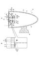
- FIG. 1 is a front view of a speaker 10 according to an embodiment of the present invention.
- FIG. 2A is a cross-sectional view taken along the line A-A ′ of FIG.
- An enclosure 11 of the speaker 10 has an opening 12 and a cavity 13 communicating with the opening 12.
- the enclosure 11 has a substantially egg shape.
- the thickness of the outer shell wall surrounding the cavity 13 in the enclosure 11 is uniform.
- the inner wall surface 14 of the enclosure 11 is curved so that the cavity 13 is substantially oval.
- Legs 16 are fixed to the outer wall surface 15 of the enclosure 11.
- the opening 12 of the enclosure 11 has a perfect circle shape.
- a speaker unit 20 is fitted in the opening 12.
- the speaker unit 20 is a device that radiates a given electric signal as a sound wave that is an air dense wave.
- the speaker unit 20 includes a vibration unit 21, a frame 22 that covers the vibration unit 21 from the cavity 13 side, a magnetic circuit 23 provided at an end of the frame 22 opposite to the vibration unit 21, and vibration in the frame 22. And a bobbin 24 interposed between the portion 21 and the magnetic circuit 23.
- the vibrating section 21 includes a honeycomb core 25 having a hollow honeycomb structure and two aluminum films 26 and 27 covering the honeycomb core 25 from both sides.
- the films 26 and 27 of the vibration part 21 have a perfect circle shape having a slightly smaller diameter than the opening 12.
- the outer periphery of the film 26 of the vibration part 21 is supported on the inner periphery of the opening 12 via an edge part 49.
- the frame 22 has a substantially conical shape.
- the frame 22 has a perfect circular opening on one side and the other side in the axial direction.
- the frame 22 is fixed to the inner peripheral portion of the opening 12 of the enclosure 11 with the larger diameter of the two openings facing the vibrating portion 21.
- the magnetic circuit 23 is a member in which the yoke 28, the permanent magnet 29, and the plate 30 are integrated.
- the magnetic circuit 23 is supported on the cavity 13 side of the part 21 so that the magnetic gap GP2 faces the vibration part 21.
- the yoke 28 of the magnetic circuit 23 includes a disk portion 31 and a center pole portion 32 that shares a central axis with the portion 31.
- a cross section (a cross section shown in FIG. 2A) obtained by cutting a plane passing through the central axis of the disk portion 31 and the center pole portion 32 in the yoke 28 is a convex shape.
- the permanent magnet 29 has an annular shape.
- the permanent magnet 29 has an N pole on one end face (for example, the end face 42) of the end faces 42 and 43 opposed in the thickness direction, and an S pole on the other end face (for example, the end face 43).
- the inner peripheral diameter of the hole in the permanent magnet 29 is larger than the outer peripheral diameter of the center pole portion 32.
- the end surface 42 of the permanent magnet 29 is fixed to the end surface 41 on the side where the center pole portion 32 is present in the disk portion 31.
- the center pole portion 32 protrudes toward the end face 43 of the permanent magnet 29 through the approximate center of the hole in the permanent magnet 29.
- the plate 30 has an annular shape that is thinner than the permanent magnet 29.
- the inner diameter of the hole in the plate 30 is larger than the outer diameter of the center pole portion 32 and smaller than the inner diameter of the hole in the permanent magnet 29.
- One end face 44 of the plate 30 is fixed to the end face 43 of the permanent magnet 29.
- the other end face 45 of the plate 30 is fixed to an end face 46 surrounding the smaller diameter opening in the frame 22.
- the inner peripheral surface of the hole in the plate 30 surrounds the outer peripheral surface of the center pole portion 32 protruding from the permanent magnet 29.
- a gap between the inner peripheral surface of the plate 30 and the outer peripheral surface of the center pole portion 32 forms a magnetic gap GP2.
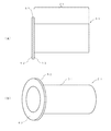
- the bobbin 24 has a coil 48 wound around the outer peripheral surface of one end of a cylindrical tube portion 51 (FIG. 2B), and an end opposite to the side where the coil 48 is wound is a flange portion 52. As shown in FIG. 2 (B), the bobbin 24 is expanded outward in the radial direction. A damper 47 is installed between the outer peripheral surface of the cylindrical portion 51 of the bobbin 24 and the inner peripheral surface of the frame 22.
- FIG. 3A is an enlarged view of the bobbin 24 of FIG.
- FIG. 3B is a perspective view of FIG.
- the flange portion 52 of the bobbin 24 has an annular shape.
- the dimension of the flange part 52 in the radial direction (the dimension of the width in the direction from the center of the flange part 52 toward the outer peripheral surface of the flange part 52) is smaller than the diameter of the cylinder part 51. Further, the end surfaces 61 and 62 facing the thickness direction of the flange portion 52 are orthogonal to the extending direction of the tube portion 51.
- the end of the bobbin 24 around which the coil 48 is wound is housed in the magnetic gap GP2 of the magnetic circuit 23.
- the end surface 62 of the flange portion 52 which is the end of the bobbin 24 opposite to the side where the coil 48 is wound, is oscillated by the soft adhesive BND. 21 is adhered to the film 27.
- the end surface 62 of the flange portion 52 of the bobbin 24 and the film 27 of the vibration portion 21 face each other in parallel.
- a soft adhesive BND is applied between the end face 62 of the flange portion 52 and the film 27 of the vibration portion 21 with a substantially uniform thickness.
- the magnetic lines of force generated by the permanent magnet 29 make a round of the yoke 28 and the plate 30, and the magnetic lines cross the magnetic gap GP2. For this reason, when a current of a sound signal is passed through the coil 48 of the bobbin 24, a driving force in a direction orthogonal to the extending direction of the coil 48 is given to the bobbin 24, and the vibration part in which the end of the bobbin 24 is bonded. 21 vibrates. An air density wave generated by the vibration of the vibrating portion 21 is radiated forward as a sound wave.
- the end of the bobbin 24 opposite to the side around which the coil 48 is wound is expanded outward in the radial direction of the bobbin 24, and the flange portion 52 which is the expanded portion. Is bonded to the vibration part 21. For this reason, if the adhesive BND is thinly applied only to a portion sandwiched between the vibration portion 21 and the flange portion 52 of the bobbin 24, sufficient bonding strength can be ensured.
- the usage fee of the adhesive can be reduced as compared with a speaker having a configuration in which the tip of the neck portion of the vibrating portion is in line contact with the outer peripheral surface of the bobbin. Therefore, according to the present embodiment, it is possible to provide a loudspeaker having a higher ability to reproduce the original sound than a loudspeaker having a configuration in which the tip of the neck portion of the vibrating portion is in line contact with the outer peripheral surface of the bobbin.
- the vibration section 21 includes a honeycomb core 25 having a hollow honeycomb structure and two aluminum films 26 and 27 sandwiching the honeycomb core 25 from both sides. For this reason, the reproduction capability of a high sound range can be made higher than the speaker which has a vibration part with another structure.
- the portion of the end of the bobbin 24 that extends outward in the radial direction of the bobbin 24 forms an annular flange 52, and the flange 52 and the film 27 face each other in parallel. is doing. For this reason, it becomes easy to make the thickness of the adhesive BND applied between the flange portion 52 and the film 27 uniform. Therefore, according to the present embodiment, the unevenness of the adhesive BND at the joint portion between the bobbin 24 and the vibration part 21 is reduced, and the bobbin 24 is more difficult to peel off.
- the inner wall surface 14 of the enclosure 11 is curved so that the cavity 13 forms a substantially egg shape. Therefore, according to this embodiment, the sound wave radiated from the vibrating portion 21 to the cavity 13 does not reciprocate along the inner wall surface 14. Therefore, according to the present embodiment, it is possible to suppress the occurrence of standing waves in the cavity 13.
- the enclosure 11 has a substantially egg shape.
- the enclosure 11 may be rectangular.
- the vibration part 21 is composed of the honeycomb core 25 and the films 26 and 27. However, you may replace this vibration part 21 with what consists of cone paper and a cap. In this case, the direction of diffusion of the flange 52, which is the end of the bobbin 24 (the end opposite to the side where the coil 48 is wound), should be the same as the angle of the tapered surface forming the outer periphery of the cone paper. .
Abstract
The present invention addresses the problem of providing a speaker that exhibits high performance in reproducing original sound. In this speaker (10), the end part of a bobbin (24) on the opposite side from the bobbin end part around which a coil (48) is wound extends outwardly in the radial direction of the bobbin (24), and the flange part (52) formed from this extended part is bonded to a vibrating part (21) with a bonding agent (BND). Thus, sufficient bonding strength can be ensured by thin application of the bonding agent (BND) to just the area between the flange part (52) and the contacting part (21) of the vibrating part (21).
Description
この発明は、スピーカの原音再生能力を高める技術に関する。
This invention relates to a technique for increasing the original sound reproduction ability of a speaker.
図4(A)は、従来の密閉型スピーカ70の構造の一例を示す図である。図4(A)のスピーカ70では、バックプレート71上にこのプレート71のセンターポール72を囲む環状マグネット73及び環状プレート74が配置されている。環状プレート74の前面にはフレーム75のネック部が固定されている。環状プレート74の内周面とセンターポール72の外周面との間の空隙である磁気ギャップGP1にはボイスコイルボビン76におけるコイル77が巻回された部分が収められている。ボイルコイルボビン76の外周面における先端から僅かに離れた部分には振動板78のネック部が接合されている。また、振動板78の表面(放音面)におけるネック部の僅かに外側にはキャップ79の周縁が接合されている。また、振動板78及びボイスコイルボビン76はフレーム75の内周面により覆われており、ボビン76の外周面とフレーム75の内周面との間にはダンパ80が架設されている。この種のスピーカの構成は、例えば、特許文献1に開示されている。
FIG. 4A is a diagram illustrating an example of the structure of a conventional sealed speaker 70. In the speaker 70 of FIG. 4A, an annular magnet 73 and an annular plate 74 surrounding the center pole 72 of the plate 71 are disposed on the back plate 71. A neck portion of the frame 75 is fixed to the front surface of the annular plate 74. A portion of the voice coil bobbin 76 around which the coil 77 is wound is accommodated in the magnetic gap GP1 which is a gap between the inner peripheral surface of the annular plate 74 and the outer peripheral surface of the center pole 72. A neck portion of the diaphragm 78 is joined to a portion of the outer peripheral surface of the boil coil bobbin 76 that is slightly away from the tip. Further, the periphery of the cap 79 is joined slightly outside the neck portion on the surface (sound emitting surface) of the diaphragm 78. The diaphragm 78 and the voice coil bobbin 76 are covered with the inner peripheral surface of the frame 75, and a damper 80 is installed between the outer peripheral surface of the bobbin 76 and the inner peripheral surface of the frame 75. The configuration of this type of speaker is disclosed in Patent Document 1, for example.
図4(B)の拡大図に示すように、この種のスピーカにおける振動板78とボビン76の接合部分は、振動板78のネック部の先端をボビン76の外周面に線接触させた構成になっており、キャップ79と振動板78の接合部分は、キャップ79の周縁を振動板78の表面に線接触させた構成になっていた。しかしながら、このような構成では、各線接触部分の前後両側に十分な量の接着剤BNDを塗付しないとその部分が容易に剥離してしまう。このため、従来のこの種のスピーカでは、音の濁りの原因となる物質である接着材の使用料が多くなり、原音再生能力を高め難いという問題があった。
As shown in the enlarged view of FIG. 4B, the joint portion of the diaphragm 78 and the bobbin 76 in this type of speaker has a configuration in which the tip of the neck portion of the diaphragm 78 is in line contact with the outer peripheral surface of the bobbin 76. The joining portion between the cap 79 and the diaphragm 78 has a configuration in which the periphery of the cap 79 is in line contact with the surface of the diaphragm 78. However, in such a configuration, if a sufficient amount of the adhesive BND is not applied to both front and rear sides of each line contact portion, the portion easily peels off. For this reason, the conventional speaker of this type has a problem that the usage fee of the adhesive, which is a substance that causes sound turbidity, increases, and it is difficult to enhance the ability to reproduce the original sound.
本発明は、このような課題に鑑みてなされたものであり、原音再生能力の高いスピーカを提供することを目的とする。
The present invention has been made in view of such problems, and an object thereof is to provide a speaker having a high original sound reproduction capability.
上記課題を解決するため、本発明は、開口とこの開口に連通した空洞とを有するエンクロージャと、前記開口の内周に支持された振動部と、磁気ギャップを有し、この磁気ギャップを前記振動部に向けるようにして前記空洞側に支持された磁気回路と、一端部の外周面にコイルが巻回され、前記コイルが巻回された方の端部が前記磁気ギャップ内に収められるとともに前記コイルが巻回された方と反対側の端部が前記振動部に接着されたボビンとを具備し、前記ボビンにおける前記コイルが巻回された方と反対側の端部がボビンの半径方向外側に向かって拡がっており、この拡がっている部分が前記振動部に接着されていることを特徴とするスピーカを提供する。
In order to solve the above problems, the present invention includes an enclosure having an opening and a cavity communicating with the opening, a vibrating portion supported on the inner periphery of the opening, and a magnetic gap. A magnetic circuit supported on the cavity side so as to face the part, and a coil is wound around the outer peripheral surface of one end, and the end on which the coil is wound is accommodated in the magnetic gap and A bobbin having an end on the opposite side to which the coil is wound and bonded to the vibrating portion, and an end on the opposite side of the bobbin on which the coil is wound is radially outward of the bobbin The speaker is characterized in that the expanded portion is bonded to the vibrating portion.
本発明では、ボビンにおけるコイルが巻回された方と反対側の端部がボビンの半径方向外側に向かって拡がっており、この拡がっている部分が振動板に接着されている。このため、振動部におけるボビンの半径方向外側に拡がっている部分との間に挟まれた部分にだけ接着剤を薄く塗付すれば十分な接合強度を確保することができる。よって、本発明によると、振動板のネック部の先端をボビンの外周面に線接触させた構成のスピーカよりも接着剤の使用料が抑えられる。従って、本発明によると、振動板のネック部の先端をボビンの外周面に線接触させた構成のスピーカよりも原音再生能力の高いスピーカを提供することができる。
In the present invention, the end of the bobbin on the side opposite to the side where the coil is wound spreads outward in the radial direction of the bobbin, and the expanded part is bonded to the diaphragm. For this reason, if the adhesive is thinly applied only to a portion sandwiched between a portion of the vibration portion that extends outward in the radial direction of the bobbin, sufficient bonding strength can be ensured. Therefore, according to the present invention, the usage fee of the adhesive can be reduced compared to a speaker having a configuration in which the tip of the neck portion of the diaphragm is in line contact with the outer peripheral surface of the bobbin. Therefore, according to the present invention, it is possible to provide a loudspeaker having a higher ability to reproduce the original sound than a loudspeaker having a configuration in which the tip of the neck portion of the diaphragm is in line contact with the outer peripheral surface of the bobbin.
以下、図面を参照しつつ本発明の実施形態について説明する。図1は、本発明の一実施形態であるスピーカ10の正面図である。図2(A)は、図1のA-A’線断面図である。このスピーカ10のエンクロージャ11は開口12とこの開口12に連通した空洞13とを有している。エンクロージャ11は略卵状をなしている。エンクロージャ11における空洞13を囲む外殻壁の厚さは均一になっている。エンクロージャ11の内壁面14は空洞13が略卵状をなすように湾曲している。エンクロージャ11の外壁面15には脚16が固定されている。エンクロージャ11の開口12は真円状をなしている。この開口12にはスピーカユニット20が嵌め込まれている。
Hereinafter, embodiments of the present invention will be described with reference to the drawings. FIG. 1 is a front view of a speaker 10 according to an embodiment of the present invention. FIG. 2A is a cross-sectional view taken along the line A-A ′ of FIG. An enclosure 11 of the speaker 10 has an opening 12 and a cavity 13 communicating with the opening 12. The enclosure 11 has a substantially egg shape. The thickness of the outer shell wall surrounding the cavity 13 in the enclosure 11 is uniform. The inner wall surface 14 of the enclosure 11 is curved so that the cavity 13 is substantially oval. Legs 16 are fixed to the outer wall surface 15 of the enclosure 11. The opening 12 of the enclosure 11 has a perfect circle shape. A speaker unit 20 is fitted in the opening 12.
スピーカユニット20は、与えられた電気信号を空気の粗密波である音波として放射する装置である。スピーカユニット20は、振動部21と、この振動部21を空洞13側から覆うフレーム22と、フレーム22における振動部21と反対側の端部に設けられた磁気回路23と、フレーム22内における振動部21と磁気回路23との間に介在するボビン24とを有する。
The speaker unit 20 is a device that radiates a given electric signal as a sound wave that is an air dense wave. The speaker unit 20 includes a vibration unit 21, a frame 22 that covers the vibration unit 21 from the cavity 13 side, a magnetic circuit 23 provided at an end of the frame 22 opposite to the vibration unit 21, and vibration in the frame 22. And a bobbin 24 interposed between the portion 21 and the magnetic circuit 23.
振動部21は、中空ハニカム構造をなすハニカムコア25とこのハニカムコア25を両側から覆う2枚のアルミニウム製のフィルム26及び27とを有する。振動部21のフィルム26及び27は開口12よりも僅かに小さな直径を持った真円状をなしている。振動部21のフィルム26の外周はエッジ部49を介して開口12の内周に支持されている。
The vibrating section 21 includes a honeycomb core 25 having a hollow honeycomb structure and two aluminum films 26 and 27 covering the honeycomb core 25 from both sides. The films 26 and 27 of the vibration part 21 have a perfect circle shape having a slightly smaller diameter than the opening 12. The outer periphery of the film 26 of the vibration part 21 is supported on the inner periphery of the opening 12 via an edge part 49.
フレーム22は略円錐状をなしている。フレーム22における軸方向の一方の側と他方の側には真円状の開口がある。フレーム22は、2つの開口のうち直径の大きい方の開口を振動部21に向けてエンクロージャ11の開口12の内周の部分に固定されている。
The frame 22 has a substantially conical shape. The frame 22 has a perfect circular opening on one side and the other side in the axial direction. The frame 22 is fixed to the inner peripheral portion of the opening 12 of the enclosure 11 with the larger diameter of the two openings facing the vibrating portion 21.
磁気回路23は、ヨーク28、永久磁石29、及びプレート30を一体化した部材である。磁気回路23は、磁気ギャップGP2を振動部21に向けるようにして同部21の空洞13側に支持されている。より具体的に説明すると、磁気回路23のヨーク28は、円盤部31および同部31と中心軸を共有するセンターポール部32を有する。ヨーク28における円盤部31及びセンターポール部32の中心軸を通る面を切断面として切断した断面(図2(A)に示す断面)は凸字状をなしている。
The magnetic circuit 23 is a member in which the yoke 28, the permanent magnet 29, and the plate 30 are integrated. The magnetic circuit 23 is supported on the cavity 13 side of the part 21 so that the magnetic gap GP2 faces the vibration part 21. More specifically, the yoke 28 of the magnetic circuit 23 includes a disk portion 31 and a center pole portion 32 that shares a central axis with the portion 31. A cross section (a cross section shown in FIG. 2A) obtained by cutting a plane passing through the central axis of the disk portion 31 and the center pole portion 32 in the yoke 28 is a convex shape.
永久磁石29は、円環状をなしている。この永久磁石29は、厚み方向に対向する端面42及び43のうち一方の端面(例えば、端面42)にN極があり、もう一方の端面(例えば、端面43)にS極がある。永久磁石29内の孔の内周径はセンターポール部32の外周径より大きくなっている。永久磁石29の端面42は円盤部31におけるセンターポール部32のある側の端面41に固定されている。センターポール部32は永久磁石29内の孔の略中心を通って永久磁石29の端面43の側に突出している。
The permanent magnet 29 has an annular shape. The permanent magnet 29 has an N pole on one end face (for example, the end face 42) of the end faces 42 and 43 opposed in the thickness direction, and an S pole on the other end face (for example, the end face 43). The inner peripheral diameter of the hole in the permanent magnet 29 is larger than the outer peripheral diameter of the center pole portion 32. The end surface 42 of the permanent magnet 29 is fixed to the end surface 41 on the side where the center pole portion 32 is present in the disk portion 31. The center pole portion 32 protrudes toward the end face 43 of the permanent magnet 29 through the approximate center of the hole in the permanent magnet 29.
プレート30は、永久磁石29よりも幅薄な円環状をなしている。プレート30内の孔の内周径は、センターポール部32の外周径より大きく永久磁石29内の孔の内周径より小さくなっている。プレート30における一方の端面44は永久磁石29の端面43に固定されている。プレート30における他方の端面45は、フレーム22における直径の小さい方の開口を囲む端面46に固定されている。プレート30内の孔の内周面はセンターポール部32における永久磁石29から突出した部分の外周面を包囲している。そして、このプレート30の内周面とセンターポール部32の外周面との間の隙間が磁気ギャップGP2を形成している。
The plate 30 has an annular shape that is thinner than the permanent magnet 29. The inner diameter of the hole in the plate 30 is larger than the outer diameter of the center pole portion 32 and smaller than the inner diameter of the hole in the permanent magnet 29. One end face 44 of the plate 30 is fixed to the end face 43 of the permanent magnet 29. The other end face 45 of the plate 30 is fixed to an end face 46 surrounding the smaller diameter opening in the frame 22. The inner peripheral surface of the hole in the plate 30 surrounds the outer peripheral surface of the center pole portion 32 protruding from the permanent magnet 29. A gap between the inner peripheral surface of the plate 30 and the outer peripheral surface of the center pole portion 32 forms a magnetic gap GP2.
ボビン24は、円筒状の筒部51(図2(B))の一端部の外周面にコイル48を巻回するとともに、コイル48が巻回された方と反対側の端部をフランジ部52(図2(B))としてボビン24の半径方向外側に拡げたものである。ボビン24の筒部51の外周面とフレーム22の内周面との間にはダンパ47が架設されている。図3(A)は、図2(A)のボビン24の拡大図である。図3(B)は、図3(A)の斜視図である。図3(A)及び図3(B)に示すように、ボビン24のフランジ部52は円環状をなしている。フランジ部52の半径方向の寸法(フランジ部52の中心からフランジ部52の外周面に向かう方向の幅の寸法)は筒部51の直径よりも小さくなっている。また、フランジ部52の厚み方向に対向する端面61及び62は筒部51の延在方向と直交している。
The bobbin 24 has a coil 48 wound around the outer peripheral surface of one end of a cylindrical tube portion 51 (FIG. 2B), and an end opposite to the side where the coil 48 is wound is a flange portion 52. As shown in FIG. 2 (B), the bobbin 24 is expanded outward in the radial direction. A damper 47 is installed between the outer peripheral surface of the cylindrical portion 51 of the bobbin 24 and the inner peripheral surface of the frame 22. FIG. 3A is an enlarged view of the bobbin 24 of FIG. FIG. 3B is a perspective view of FIG. As shown in FIGS. 3A and 3B, the flange portion 52 of the bobbin 24 has an annular shape. The dimension of the flange part 52 in the radial direction (the dimension of the width in the direction from the center of the flange part 52 toward the outer peripheral surface of the flange part 52) is smaller than the diameter of the cylinder part 51. Further, the end surfaces 61 and 62 facing the thickness direction of the flange portion 52 are orthogonal to the extending direction of the tube portion 51.
図2(A)に示すように、ボビン24におけるコイル48が巻回された方の端部は磁気回路23の磁気ギャップGP2内に収められている。また、図2(B)の拡大図に示すように、ボビン24におけるコイル48が巻回されている方と反対側の端部であるフランジ部52の端面62は、軟性接着剤BNDにより振動部21のフィルム27に接着されている。ボビン24のフランジ部52の端面62と振動部21のフィルム27は平行に対峙している。そして、このフランジ部52の端面62と振動部21のフィルム27との間には軟性接着剤BNDが略均一の厚さで塗られている。
As shown in FIG. 2A, the end of the bobbin 24 around which the coil 48 is wound is housed in the magnetic gap GP2 of the magnetic circuit 23. Further, as shown in the enlarged view of FIG. 2B, the end surface 62 of the flange portion 52, which is the end of the bobbin 24 opposite to the side where the coil 48 is wound, is oscillated by the soft adhesive BND. 21 is adhered to the film 27. The end surface 62 of the flange portion 52 of the bobbin 24 and the film 27 of the vibration portion 21 face each other in parallel. A soft adhesive BND is applied between the end face 62 of the flange portion 52 and the film 27 of the vibration portion 21 with a substantially uniform thickness.
この磁気回路23では、永久磁石29が発生した磁力線が、ヨーク28およびプレート30を一巡し、この磁力線が磁気ギャップGP2を横切る。このため、ボビン24のコイル48に音信号の電流を流すと、ボビン24にはコイル48の延在方向と直交する方向の駆動力が与えられ、ボビン24とその端部が接着された振動部21が振動する。この振動部21の振動により発生した空気の粗密波が音波として前方に放射される。
In this magnetic circuit 23, the magnetic lines of force generated by the permanent magnet 29 make a round of the yoke 28 and the plate 30, and the magnetic lines cross the magnetic gap GP2. For this reason, when a current of a sound signal is passed through the coil 48 of the bobbin 24, a driving force in a direction orthogonal to the extending direction of the coil 48 is given to the bobbin 24, and the vibration part in which the end of the bobbin 24 is bonded. 21 vibrates. An air density wave generated by the vibration of the vibrating portion 21 is radiated forward as a sound wave.
以上が、本実施形態の構成の詳細である。本実施形態によると、次の効果が得られる。
第1に、本実施形態では、ボビン24におけるコイル48が巻回された方と反対側の端部がボビン24の半径方向外側に向かって拡がっており、この拡がっている部分であるフランジ部52が振動部21に接着されている。このため、振動部21におけるボビン24のフランジ部52との間に挟まれた部分にだけ接着剤BNDを薄く塗付すれば十分な接合強度を確保することができる。よって、本実施形態によると、振動部のネック部の先端をボビンの外周面に線接触させた構成のスピーカよりも接着剤の使用料が抑えられる。従って、本実施形態によると、振動部のネック部の先端をボビンの外周面に線接触させた構成のスピーカよりも原音再生能力の高いスピーカを提供することができる。 The above is the details of the configuration of the present embodiment. According to this embodiment, the following effects can be obtained.
First, in the present embodiment, the end of thebobbin 24 opposite to the side around which the coil 48 is wound is expanded outward in the radial direction of the bobbin 24, and the flange portion 52 which is the expanded portion. Is bonded to the vibration part 21. For this reason, if the adhesive BND is thinly applied only to a portion sandwiched between the vibration portion 21 and the flange portion 52 of the bobbin 24, sufficient bonding strength can be ensured. Therefore, according to this embodiment, the usage fee of the adhesive can be reduced as compared with a speaker having a configuration in which the tip of the neck portion of the vibrating portion is in line contact with the outer peripheral surface of the bobbin. Therefore, according to the present embodiment, it is possible to provide a loudspeaker having a higher ability to reproduce the original sound than a loudspeaker having a configuration in which the tip of the neck portion of the vibrating portion is in line contact with the outer peripheral surface of the bobbin.
第1に、本実施形態では、ボビン24におけるコイル48が巻回された方と反対側の端部がボビン24の半径方向外側に向かって拡がっており、この拡がっている部分であるフランジ部52が振動部21に接着されている。このため、振動部21におけるボビン24のフランジ部52との間に挟まれた部分にだけ接着剤BNDを薄く塗付すれば十分な接合強度を確保することができる。よって、本実施形態によると、振動部のネック部の先端をボビンの外周面に線接触させた構成のスピーカよりも接着剤の使用料が抑えられる。従って、本実施形態によると、振動部のネック部の先端をボビンの外周面に線接触させた構成のスピーカよりも原音再生能力の高いスピーカを提供することができる。 The above is the details of the configuration of the present embodiment. According to this embodiment, the following effects can be obtained.
First, in the present embodiment, the end of the
第2に、本実施形態では、振動部21は、中空ハニカム構造をなすハニカムコア25と、ハニカムコア25を両側から挟む2枚のアルミニウム製のフィルム26,27とから構成されている。このため、他の構成を持った振動部を有するスピーカよりも高音域の再現能力を高くすることができる。
Secondly, in the present embodiment, the vibration section 21 includes a honeycomb core 25 having a hollow honeycomb structure and two aluminum films 26 and 27 sandwiching the honeycomb core 25 from both sides. For this reason, the reproduction capability of a high sound range can be made higher than the speaker which has a vibration part with another structure.
第3に、本実施形態では、ボビン24の端部におけるボビン24の半径方向外側に向かって広がっている部分は円環状のフランジ部52を形成し、フランジ部52とフィルム27とが平行に対峙している。このため、フランジ部52とフィルム27の間に塗付する接着剤BNDの厚みを均一にし易くなる。よって、本実施形態によると、ボビン24と振動部21との接合部分の接着剤BNDのムラが少なくなり、ボビン24がより一層剥離し難くなる。
Thirdly, in the present embodiment, the portion of the end of the bobbin 24 that extends outward in the radial direction of the bobbin 24 forms an annular flange 52, and the flange 52 and the film 27 face each other in parallel. is doing. For this reason, it becomes easy to make the thickness of the adhesive BND applied between the flange portion 52 and the film 27 uniform. Therefore, according to the present embodiment, the unevenness of the adhesive BND at the joint portion between the bobbin 24 and the vibration part 21 is reduced, and the bobbin 24 is more difficult to peel off.
第4に、本実施形態では、エンクロージャ11の内壁面14は、空洞13が略卵状をなすように湾曲している。よって、本実施形態によると、振動部21から空洞13に放射された音波が内壁面14を往復移動しなくなる。従って、本実施形態によると、空洞13内における定在波の発生を抑制することができる。
Fourthly, in the present embodiment, the inner wall surface 14 of the enclosure 11 is curved so that the cavity 13 forms a substantially egg shape. Therefore, according to this embodiment, the sound wave radiated from the vibrating portion 21 to the cavity 13 does not reciprocate along the inner wall surface 14. Therefore, according to the present embodiment, it is possible to suppress the occurrence of standing waves in the cavity 13.
以上、本発明の一実施形態について説明したが、かかる実施形態に以下の変形を加えてもよい。
(1)上記実施形態では、エンクロージャ11は略卵状をなしていた。しかし、エンクロージャ11を矩形状にしてもよい。 As mentioned above, although one Embodiment of this invention was described, you may add the following modifications to this embodiment.
(1) In the above embodiment, theenclosure 11 has a substantially egg shape. However, the enclosure 11 may be rectangular.
(1)上記実施形態では、エンクロージャ11は略卵状をなしていた。しかし、エンクロージャ11を矩形状にしてもよい。 As mentioned above, although one Embodiment of this invention was described, you may add the following modifications to this embodiment.
(1) In the above embodiment, the
(2)上記実施形態では、振動部21は、ハニカムコア25とフィルム26及び27とから構成されていた。しかし、この振動部21を、コーン紙とキャップとから構成されるものに置き換えてもよい。この場合、ボビン24の端部(コイル48が巻回されている方と反対側の端部)であるフランジ部52の拡散の方向をコーン紙の外周をなすテーパ面の角度と同じにするとよい。
(2) In the above embodiment, the vibration part 21 is composed of the honeycomb core 25 and the films 26 and 27. However, you may replace this vibration part 21 with what consists of cone paper and a cap. In this case, the direction of diffusion of the flange 52, which is the end of the bobbin 24 (the end opposite to the side where the coil 48 is wound), should be the same as the angle of the tapered surface forming the outer periphery of the cone paper. .
10,70…スピーカ、11…エンクロージャ、12…開口、13…空洞、14…内壁面、15…外壁面、16…脚、21…振動部、22…フレーム、23…磁気回路、24,76…ボビン、25…ハニカムコア、26,27…フィルム、28…ヨーク部、29…永久磁石、30…プレート、31…円盤部、32,72…センターポール部、48…コイル、49…エッジ部、51…筒部、52…フランジ部、71…バックプレート、78…振動板、79…キャップ。
DESCRIPTION OF SYMBOLS 10,70 ... Speaker, 11 ... Enclosure, 12 ... Opening, 13 ... Cavity, 14 ... Inner wall surface, 15 ... Outer wall surface, 16 ... Leg, 21 ... Vibrating part, 22 ... Frame, 23 ... Magnetic circuit, 24, 76 ... Bobbin, 25 ... honeycomb core, 26, 27 ... film, 28 ... yoke part, 29 ... permanent magnet, 30 ... plate, 31 ... disk part, 32, 72 ... center pole part, 48 ... coil, 49 ... edge part, 51 ... cylinder part, 52 ... flange part, 71 ... back plate, 78 ... diaphragm, 79 ... cap.
DESCRIPTION OF
Claims (4)
- 開口とこの開口に連通した空洞とを有するエンクロージャと、
前記開口の内周に支持された振動部と、
磁気ギャップを有し、この磁気ギャップを前記振動部に向けるようにして前記空洞側に支持された磁気回路と、
一端部の外周面にコイルが巻回され、前記コイルが巻回された方の端部が前記磁気ギャップ内に収められるとともに前記コイルが巻回された方と反対側の端部が前記振動部に接着されたボビンと
を具備し、
前記ボビンにおける前記コイルが巻回された方と反対側の端部がボビンの半径方向外側に向かって拡がっており、この拡がっている部分が前記振動部に接着されていることを特徴とするスピーカ。 An enclosure having an opening and a cavity communicating with the opening;
A vibrating portion supported on the inner periphery of the opening;
A magnetic circuit having a magnetic gap and supported on the cavity side so that the magnetic gap faces the vibrating portion;
A coil is wound around the outer peripheral surface of one end, the end on which the coil is wound is stored in the magnetic gap, and the end opposite to the side on which the coil is wound is the vibrating portion. And a bobbin bonded to
The speaker is characterized in that an end of the bobbin opposite to the side where the coil is wound widens outward in the radial direction of the bobbin, and the widened part is bonded to the vibrating part. . - 前記振動部は、
中空ハニカム構造をなすハニカムコアと、前記ハニカムコアを両側から挟む2枚のアルミニウム製のフィルムとを有することを特徴とする請求項1に記載のスピーカ。 The vibrating part is
The speaker according to claim 1, comprising a honeycomb core having a hollow honeycomb structure and two aluminum films sandwiching the honeycomb core from both sides. - 前記ボビンの端部におけるボビンの半径方向外側に向かって広がっている部分は円環状のフランジ部を形成し、前記フランジ部と前記2枚のフィルムのうち前記空洞側のフィルムとが平行に対峙していることを特徴とする請求項2に記載のスピーカ。 A portion of the end portion of the bobbin that extends outward in the radial direction of the bobbin forms an annular flange portion, and the flange portion and the film on the cavity side of the two films face each other in parallel. The speaker according to claim 2, wherein:
- 前記エンクロージャの内壁面は、前記空洞が略卵状をなすように湾曲していることを特徴とする請求項3に記載のスピーカ。 The speaker according to claim 3, wherein the inner wall surface of the enclosure is curved so that the cavity has an approximately egg shape.
Priority Applications (1)
| Application Number | Priority Date | Filing Date | Title |
|---|---|---|---|
| CN201290000171.9U CN203596912U (en) | 2012-09-07 | 2012-12-28 | Loudspeaker |
Applications Claiming Priority (2)
| Application Number | Priority Date | Filing Date | Title |
|---|---|---|---|
| JP2012-197934 | 2012-09-07 | ||
| JP2012197934 | 2012-09-07 |
Publications (1)
| Publication Number | Publication Date |
|---|---|
| WO2014038102A1 true WO2014038102A1 (en) | 2014-03-13 |
Family
ID=50236743
Family Applications (1)
| Application Number | Title | Priority Date | Filing Date |
|---|---|---|---|
| PCT/JP2012/084015 WO2014038102A1 (en) | 2012-09-07 | 2012-12-28 | Speaker |
Country Status (4)
| Country | Link |
|---|---|
| JP (2) | JP5731602B2 (en) |
| CN (1) | CN203596912U (en) |
| HK (1) | HK1222279A1 (en) |
| WO (1) | WO2014038102A1 (en) |
Cited By (1)
| Publication number | Priority date | Publication date | Assignee | Title |
|---|---|---|---|---|
| US9532132B2 (en) | 2013-09-09 | 2016-12-27 | Shinichirou NAKAISHI | Hearing-impaired person assistance speaker |
Families Citing this family (3)
| Publication number | Priority date | Publication date | Assignee | Title |
|---|---|---|---|---|
| JP6282172B2 (en) * | 2014-05-19 | 2018-02-21 | シャープ株式会社 | Speaker box and television receiver |
| JP6614158B2 (en) * | 2014-12-02 | 2019-12-04 | ソニー株式会社 | Speaker device |
| JP7091900B2 (en) * | 2018-07-17 | 2022-06-28 | ヤマハ株式会社 | Electro-acoustic converter |
Citations (3)
| Publication number | Priority date | Publication date | Assignee | Title |
|---|---|---|---|---|
| JPS6068796U (en) * | 1983-10-19 | 1985-05-15 | ソニー株式会社 | flat speaker |
| JP2003304585A (en) * | 2002-04-12 | 2003-10-24 | Kenwood Corp | Speaker system |
| JP2005005815A (en) * | 2003-06-09 | 2005-01-06 | Fujitsu Ten Ltd | Supporter |
Family Cites Families (8)
| Publication number | Priority date | Publication date | Assignee | Title |
|---|---|---|---|---|
| JPS56147687U (en) * | 1980-04-04 | 1981-11-06 | ||
| JPS57101494A (en) * | 1980-12-16 | 1982-06-24 | Matsushita Electric Ind Co Ltd | Manufacture for core member of vibration diaphragm for speaker |
| JPS59125195U (en) * | 1983-02-10 | 1984-08-23 | ソニー株式会社 | flat speaker |
| JP3484143B2 (en) * | 1999-12-02 | 2004-01-06 | 株式会社タイムドメイン | Speaker device |
| JP2002247675A (en) * | 2001-02-14 | 2002-08-30 | Time Domain:Kk | Speaker system |
| JP2008137514A (en) * | 2006-12-01 | 2008-06-19 | Kenwood Corp | On-vehicle audio system and tweeter speaker unit with on-vehicle microphone |
| WO2009113319A1 (en) * | 2008-03-13 | 2009-09-17 | タカノ株式会社 | Chair with built-in speaker |
| GB0811015D0 (en) * | 2008-06-17 | 2008-07-23 | Deben Acoustics | Improved acoustic device |
-
2012
- 2012-12-28 WO PCT/JP2012/084015 patent/WO2014038102A1/en active Application Filing
- 2012-12-28 CN CN201290000171.9U patent/CN203596912U/en not_active Expired - Lifetime
-
2013
- 2013-09-09 JP JP2013185848A patent/JP5731602B2/en active Active
-
2015
- 2015-04-06 JP JP2015077756A patent/JP6250582B2/en active Active
-
2016
- 2016-08-30 HK HK16110307.9A patent/HK1222279A1/en unknown
Patent Citations (3)
| Publication number | Priority date | Publication date | Assignee | Title |
|---|---|---|---|---|
| JPS6068796U (en) * | 1983-10-19 | 1985-05-15 | ソニー株式会社 | flat speaker |
| JP2003304585A (en) * | 2002-04-12 | 2003-10-24 | Kenwood Corp | Speaker system |
| JP2005005815A (en) * | 2003-06-09 | 2005-01-06 | Fujitsu Ten Ltd | Supporter |
Cited By (1)
| Publication number | Priority date | Publication date | Assignee | Title |
|---|---|---|---|---|
| US9532132B2 (en) | 2013-09-09 | 2016-12-27 | Shinichirou NAKAISHI | Hearing-impaired person assistance speaker |
Also Published As
| Publication number | Publication date |
|---|---|
| HK1222279A1 (en) | 2017-06-23 |
| JP2014068342A (en) | 2014-04-17 |
| CN203596912U (en) | 2014-05-14 |
| JP2015146632A (en) | 2015-08-13 |
| JP5731602B2 (en) | 2015-06-10 |
| JP6250582B2 (en) | 2017-12-20 |
Similar Documents
| Publication | Publication Date | Title |
|---|---|---|
| US10299035B2 (en) | Acoustic lens system for loudspeakers | |
| JP2007235232A (en) | Speaker | |
| US9756426B2 (en) | Loudspeaker | |
| WO2014038102A1 (en) | Speaker | |
| WO2010050056A1 (en) | Speaker connecting member, and speaker | |
| WO2015033970A1 (en) | Speaker for supporting hearing-impaired people | |
| JP6482004B2 (en) | Speaker | |
| JP2010034988A (en) | Speaker system | |
| JP6993459B2 (en) | Electroacoustic driver | |
| JP5327616B2 (en) | Speaker unit | |
| JP5825522B2 (en) | Speaker device | |
| JPH0349515Y2 (en) | ||
| JP6989751B2 (en) | Dust cap and electrokinetic speaker using it | |
| JP2008167247A (en) | Voice coil motor and speaker using the same | |
| JP6711487B2 (en) | Electro-acoustic transducer | |
| JP2016052076A (en) | Flat diaphragm for loudspeaker and loudspeaker using the same | |
| JP2015070600A (en) | Capacitor headphone unit and method of manufacturing fixed pole assembly of capacitor headphone | |
| WO2019077925A1 (en) | Loudspeaker and diaphragm unit | |
| JP2019030003A (en) | Speaker and manufacturing method of speaker | |
| JP7454459B2 (en) | speaker | |
| JP2008271025A (en) | Edge for speaker and speaker system | |
| JP2008205880A (en) | Ring type speaker and speaker system using the same | |
| JP4417817B2 (en) | Speaker | |
| JP5311223B2 (en) | Center cap for speaker and speaker unit with cap | |
| JP2022150705A (en) | speaker device |
Legal Events
| Date | Code | Title | Description |
|---|---|---|---|
| WWE | Wipo information: entry into national phase |
Ref document number: 201290000171.9 Country of ref document: CN |
|
| 121 | Ep: the epo has been informed by wipo that ep was designated in this application |
Ref document number: 12884211 Country of ref document: EP Kind code of ref document: A1 |
|
| NENP | Non-entry into the national phase |
Ref country code: DE |
|
| 122 | Ep: pct application non-entry in european phase |
Ref document number: 12884211 Country of ref document: EP Kind code of ref document: A1 |