WO2014034660A1 - 樹脂製パレット - Google Patents
樹脂製パレット Download PDFInfo
- Publication number
- WO2014034660A1 WO2014034660A1 PCT/JP2013/072865 JP2013072865W WO2014034660A1 WO 2014034660 A1 WO2014034660 A1 WO 2014034660A1 JP 2013072865 W JP2013072865 W JP 2013072865W WO 2014034660 A1 WO2014034660 A1 WO 2014034660A1
- Authority
- WO
- WIPO (PCT)
- Prior art keywords
- girder
- resin pallet
- fork insertion
- ribs
- rib
- Prior art date
- Legal status (The legal status is an assumption and is not a legal conclusion. Google has not performed a legal analysis and makes no representation as to the accuracy of the status listed.)
- Ceased
Links
Images




Classifications
-
- B—PERFORMING OPERATIONS; TRANSPORTING
- B65—CONVEYING; PACKING; STORING; HANDLING THIN OR FILAMENTARY MATERIAL
- B65D—CONTAINERS FOR STORAGE OR TRANSPORT OF ARTICLES OR MATERIALS, e.g. BAGS, BARRELS, BOTTLES, BOXES, CANS, CARTONS, CRATES, DRUMS, JARS, TANKS, HOPPERS, FORWARDING CONTAINERS; ACCESSORIES, CLOSURES, OR FITTINGS THEREFOR; PACKAGING ELEMENTS; PACKAGES
- B65D19/00—Pallets or like platforms, with or without side walls, for supporting loads to be lifted or lowered
- B65D19/0004—Rigid pallets without side walls
- B65D19/0006—Rigid pallets without side walls the load supporting surface being made of a single element
- B65D19/0008—Rigid pallets without side walls the load supporting surface being made of a single element forming a continuous plane contact surface
- B65D19/001—Rigid pallets without side walls the load supporting surface being made of a single element forming a continuous plane contact surface the base surface being made of a single element
- B65D19/0012—Rigid pallets without side walls the load supporting surface being made of a single element forming a continuous plane contact surface the base surface being made of a single element forming a continuous plane contact surface
-
- B—PERFORMING OPERATIONS; TRANSPORTING
- B65—CONVEYING; PACKING; STORING; HANDLING THIN OR FILAMENTARY MATERIAL
- B65D—CONTAINERS FOR STORAGE OR TRANSPORT OF ARTICLES OR MATERIALS, e.g. BAGS, BARRELS, BOTTLES, BOXES, CANS, CARTONS, CRATES, DRUMS, JARS, TANKS, HOPPERS, FORWARDING CONTAINERS; ACCESSORIES, CLOSURES, OR FITTINGS THEREFOR; PACKAGING ELEMENTS; PACKAGES
- B65D19/00—Pallets or like platforms, with or without side walls, for supporting loads to be lifted or lowered
- B65D19/0004—Rigid pallets without side walls
- B65D19/0053—Rigid pallets without side walls the load supporting surface being made of more than one element
- B65D19/0055—Rigid pallets without side walls the load supporting surface being made of more than one element forming a continuous plane contact surface
-
- B—PERFORMING OPERATIONS; TRANSPORTING
- B65—CONVEYING; PACKING; STORING; HANDLING THIN OR FILAMENTARY MATERIAL
- B65D—CONTAINERS FOR STORAGE OR TRANSPORT OF ARTICLES OR MATERIALS, e.g. BAGS, BARRELS, BOTTLES, BOXES, CANS, CARTONS, CRATES, DRUMS, JARS, TANKS, HOPPERS, FORWARDING CONTAINERS; ACCESSORIES, CLOSURES, OR FITTINGS THEREFOR; PACKAGING ELEMENTS; PACKAGES
- B65D19/00—Pallets or like platforms, with or without side walls, for supporting loads to be lifted or lowered
- B65D19/38—Details or accessories
-
- B—PERFORMING OPERATIONS; TRANSPORTING
- B65—CONVEYING; PACKING; STORING; HANDLING THIN OR FILAMENTARY MATERIAL
- B65D—CONTAINERS FOR STORAGE OR TRANSPORT OF ARTICLES OR MATERIALS, e.g. BAGS, BARRELS, BOTTLES, BOXES, CANS, CARTONS, CRATES, DRUMS, JARS, TANKS, HOPPERS, FORWARDING CONTAINERS; ACCESSORIES, CLOSURES, OR FITTINGS THEREFOR; PACKAGING ELEMENTS; PACKAGES
- B65D2519/00—Pallets or like platforms, with or without side walls, for supporting loads to be lifted or lowered
- B65D2519/00004—Details relating to pallets
- B65D2519/00009—Materials
- B65D2519/00014—Materials for the load supporting surface
- B65D2519/00034—Plastic
-
- B—PERFORMING OPERATIONS; TRANSPORTING
- B65—CONVEYING; PACKING; STORING; HANDLING THIN OR FILAMENTARY MATERIAL
- B65D—CONTAINERS FOR STORAGE OR TRANSPORT OF ARTICLES OR MATERIALS, e.g. BAGS, BARRELS, BOTTLES, BOXES, CANS, CARTONS, CRATES, DRUMS, JARS, TANKS, HOPPERS, FORWARDING CONTAINERS; ACCESSORIES, CLOSURES, OR FITTINGS THEREFOR; PACKAGING ELEMENTS; PACKAGES
- B65D2519/00—Pallets or like platforms, with or without side walls, for supporting loads to be lifted or lowered
- B65D2519/00004—Details relating to pallets
- B65D2519/00009—Materials
- B65D2519/00049—Materials for the base surface
- B65D2519/00069—Plastic
-
- B—PERFORMING OPERATIONS; TRANSPORTING
- B65—CONVEYING; PACKING; STORING; HANDLING THIN OR FILAMENTARY MATERIAL
- B65D—CONTAINERS FOR STORAGE OR TRANSPORT OF ARTICLES OR MATERIALS, e.g. BAGS, BARRELS, BOTTLES, BOXES, CANS, CARTONS, CRATES, DRUMS, JARS, TANKS, HOPPERS, FORWARDING CONTAINERS; ACCESSORIES, CLOSURES, OR FITTINGS THEREFOR; PACKAGING ELEMENTS; PACKAGES
- B65D2519/00—Pallets or like platforms, with or without side walls, for supporting loads to be lifted or lowered
- B65D2519/00004—Details relating to pallets
- B65D2519/00258—Overall construction
- B65D2519/00263—Overall construction of the pallet
- B65D2519/00273—Overall construction of the pallet made of more than one piece
-
- B—PERFORMING OPERATIONS; TRANSPORTING
- B65—CONVEYING; PACKING; STORING; HANDLING THIN OR FILAMENTARY MATERIAL
- B65D—CONTAINERS FOR STORAGE OR TRANSPORT OF ARTICLES OR MATERIALS, e.g. BAGS, BARRELS, BOTTLES, BOXES, CANS, CARTONS, CRATES, DRUMS, JARS, TANKS, HOPPERS, FORWARDING CONTAINERS; ACCESSORIES, CLOSURES, OR FITTINGS THEREFOR; PACKAGING ELEMENTS; PACKAGES
- B65D2519/00—Pallets or like platforms, with or without side walls, for supporting loads to be lifted or lowered
- B65D2519/00004—Details relating to pallets
- B65D2519/00258—Overall construction
- B65D2519/00283—Overall construction of the load supporting surface
- B65D2519/00288—Overall construction of the load supporting surface made of one piece
-
- B—PERFORMING OPERATIONS; TRANSPORTING
- B65—CONVEYING; PACKING; STORING; HANDLING THIN OR FILAMENTARY MATERIAL
- B65D—CONTAINERS FOR STORAGE OR TRANSPORT OF ARTICLES OR MATERIALS, e.g. BAGS, BARRELS, BOTTLES, BOXES, CANS, CARTONS, CRATES, DRUMS, JARS, TANKS, HOPPERS, FORWARDING CONTAINERS; ACCESSORIES, CLOSURES, OR FITTINGS THEREFOR; PACKAGING ELEMENTS; PACKAGES
- B65D2519/00—Pallets or like platforms, with or without side walls, for supporting loads to be lifted or lowered
- B65D2519/00004—Details relating to pallets
- B65D2519/00258—Overall construction
- B65D2519/00283—Overall construction of the load supporting surface
- B65D2519/00303—Cell type, e.g. honeycomb
-
- B—PERFORMING OPERATIONS; TRANSPORTING
- B65—CONVEYING; PACKING; STORING; HANDLING THIN OR FILAMENTARY MATERIAL
- B65D—CONTAINERS FOR STORAGE OR TRANSPORT OF ARTICLES OR MATERIALS, e.g. BAGS, BARRELS, BOTTLES, BOXES, CANS, CARTONS, CRATES, DRUMS, JARS, TANKS, HOPPERS, FORWARDING CONTAINERS; ACCESSORIES, CLOSURES, OR FITTINGS THEREFOR; PACKAGING ELEMENTS; PACKAGES
- B65D2519/00—Pallets or like platforms, with or without side walls, for supporting loads to be lifted or lowered
- B65D2519/00004—Details relating to pallets
- B65D2519/00258—Overall construction
- B65D2519/00313—Overall construction of the base surface
- B65D2519/00318—Overall construction of the base surface made of one piece
-
- B—PERFORMING OPERATIONS; TRANSPORTING
- B65—CONVEYING; PACKING; STORING; HANDLING THIN OR FILAMENTARY MATERIAL
- B65D—CONTAINERS FOR STORAGE OR TRANSPORT OF ARTICLES OR MATERIALS, e.g. BAGS, BARRELS, BOTTLES, BOXES, CANS, CARTONS, CRATES, DRUMS, JARS, TANKS, HOPPERS, FORWARDING CONTAINERS; ACCESSORIES, CLOSURES, OR FITTINGS THEREFOR; PACKAGING ELEMENTS; PACKAGES
- B65D2519/00—Pallets or like platforms, with or without side walls, for supporting loads to be lifted or lowered
- B65D2519/00004—Details relating to pallets
- B65D2519/00258—Overall construction
- B65D2519/00313—Overall construction of the base surface
- B65D2519/00328—Overall construction of the base surface shape of the contact surface of the base
- B65D2519/00343—Overall construction of the base surface shape of the contact surface of the base contact surface being substantially in the form of a panel
-
- B—PERFORMING OPERATIONS; TRANSPORTING
- B65—CONVEYING; PACKING; STORING; HANDLING THIN OR FILAMENTARY MATERIAL
- B65D—CONTAINERS FOR STORAGE OR TRANSPORT OF ARTICLES OR MATERIALS, e.g. BAGS, BARRELS, BOTTLES, BOXES, CANS, CARTONS, CRATES, DRUMS, JARS, TANKS, HOPPERS, FORWARDING CONTAINERS; ACCESSORIES, CLOSURES, OR FITTINGS THEREFOR; PACKAGING ELEMENTS; PACKAGES
- B65D2519/00—Pallets or like platforms, with or without side walls, for supporting loads to be lifted or lowered
- B65D2519/00004—Details relating to pallets
- B65D2519/00258—Overall construction
- B65D2519/00313—Overall construction of the base surface
- B65D2519/00358—Cell type, e.g. honeycomb
-
- B—PERFORMING OPERATIONS; TRANSPORTING
- B65—CONVEYING; PACKING; STORING; HANDLING THIN OR FILAMENTARY MATERIAL
- B65D—CONTAINERS FOR STORAGE OR TRANSPORT OF ARTICLES OR MATERIALS, e.g. BAGS, BARRELS, BOTTLES, BOXES, CANS, CARTONS, CRATES, DRUMS, JARS, TANKS, HOPPERS, FORWARDING CONTAINERS; ACCESSORIES, CLOSURES, OR FITTINGS THEREFOR; PACKAGING ELEMENTS; PACKAGES
- B65D2519/00—Pallets or like platforms, with or without side walls, for supporting loads to be lifted or lowered
- B65D2519/00004—Details relating to pallets
- B65D2519/00547—Connections
- B65D2519/00552—Structures connecting the constitutive elements of the pallet to each other, i.e. load supporting surface, base surface and/or separate spacer
- B65D2519/00557—Structures connecting the constitutive elements of the pallet to each other, i.e. load supporting surface, base surface and/or separate spacer without separate auxiliary elements
- B65D2519/00562—Structures connecting the constitutive elements of the pallet to each other, i.e. load supporting surface, base surface and/or separate spacer without separate auxiliary elements chemical connection, e.g. glued, welded, sealed
-
- B—PERFORMING OPERATIONS; TRANSPORTING
- B65—CONVEYING; PACKING; STORING; HANDLING THIN OR FILAMENTARY MATERIAL
- B65D—CONTAINERS FOR STORAGE OR TRANSPORT OF ARTICLES OR MATERIALS, e.g. BAGS, BARRELS, BOTTLES, BOXES, CANS, CARTONS, CRATES, DRUMS, JARS, TANKS, HOPPERS, FORWARDING CONTAINERS; ACCESSORIES, CLOSURES, OR FITTINGS THEREFOR; PACKAGING ELEMENTS; PACKAGES
- B65D2519/00—Pallets or like platforms, with or without side walls, for supporting loads to be lifted or lowered
- B65D2519/00004—Details relating to pallets
- B65D2519/00736—Details
- B65D2519/00776—Accessories for manipulating the pallet
- B65D2519/00796—Guiding means for fork-lift
Definitions
- the present invention relates to a resin pallet used for storing and transporting luggage and the like, and relates to an improvement for improving strength and weight.
- both ends of the upper deck board and the lower deck board are arranged with both end girders, and the middle girder is arranged in the middle so that a space for inserting the fork is provided. Two rows are formed.
- the above-mentioned pallets made of synthetic resin have the characteristics that they are excellent in corrosion resistance, light weight, inexpensive and easy to manufacture, but there are many problems in terms of impact strength, etc. In such a case, there is a risk of breakage or the like. In addition, there may be a problem such as deformation when a load is applied. Under such circumstances, in the resin pallet, various proposals for improvement in strength and prevention of deformation have been proposed.
- ribs are formed.
- a grid-like pattern is formed vertically and horizontally in a girder or a fork insertion region.
- a synthetic resin pallet provided with ribs is disclosed.
- Patent Document 2 includes a reinforcing rib in a lattice shape formed in the fork insertion portion on the inner surface of the deck board portion, and a reinforcing beam on the extension line of the rib extending perpendicularly to the fork insertion portion among the reinforcement ribs.
- a synthetic resin pallet provided with is disclosed. In the synthetic resin pallet described in Patent Document 2, it is considered that the strength of the girder peripheral wall is improved by providing a reinforcing beam.
- Patent Document 3 a parallel reinforcing wall having the same height as the peripheral wall of the girders is provided inside the peripheral walls of both end girders and intermediate girders to improve impact strength and bend the entire pallet.
- a two-way synthetic resin pallet with improved strength is disclosed.
- the impact resistance is improved by forming a hollow structure in which the reinforcing wall and the peripheral walls of both end girders are connected and closed.
- the hollow structure contributes to an improvement in bending strength, and an effect that the amount of deformation of the pallet can be reduced is obtained.
- Patent Document 4 the corners of the support column at the entrance portion of the fork insertion hole are formed on a flat wall, the inner surface of the flat wall is orthogonal to the flat wall, and the reinforcing rib extends over the entire height of the support column.
- a pallet made of synthetic resin is disclosed. In the synthetic resin pallet described in Patent Document 4, by providing the reinforcing rib, the impact resistance around the fork insertion hole is improved.
- Patent Document 5 discloses a two-way synthetic resin pallet having a handle opening.
- the thickness of the deck board in a predetermined region surrounding the opening for the handle is made thicker than the thickness of the other portions, and a round is formed at the opening corner on the inner side. This prevents the hands from becoming painful when lifting the synthetic resin pallet, and prevents rainwater, washing water, dust, and the like from accumulating in the synthetic resin pallet.
- the pitch of the rib formed in the girder and the rib formed in the fork insertion region is the same, and the ribs are formed in the same manner in the girder and the fork insertion region.
- a reinforcing wall having the same height as the peripheral wall of the girder is provided, and furthermore, a hollow structure is formed by the connecting wall. Is expected to be a level that cannot be ignored.
- a reinforcing beam having a thickness larger than that of the rib and having the tip equal to the height of the girder peripheral wall is provided. The weight increase due to installation is considered to be large.
- the reinforcing rib is formed so as to be connected to other ribs, and the weight increase due to the formation of the reinforcing rib is expected to be a level that cannot be ignored. .
- the pallet made of synthetic resin needs to be resistant to impact caused by dropping, etc., for example, when the pallet falls, the corner is easily damaged when it collides with the ground from the corner.
- the reinforcing structure of the synthetic resin pallet disclosed in Patent Document 4 is insufficient.
- the impact resistance strength, the bending strength, and the like are improved. Therefore, it is desired to realize a structure that can secure a strength that can withstand an impact caused by dropping or the like while suppressing an increase in weight as much as possible.
- the pallet made of synthetic resin disclosed in Patent Document 4 has the characteristics that it is excellent in corrosion resistance, lightweight, inexpensive and easy to manufacture.
- a problem such as deformation occurs due to a load applied to this portion.
- some reinforcement can be considered. However, if reinforcement is performed, the weight tends to increase.
- the present invention has been proposed in view of such a conventional situation, and it is possible to secure sufficient impact strength and bending strength with a minimum amount of resin and to further reduce the weight. It is an object to provide a resin pallet that can be used.
- the resin pallet of the present invention is characterized in that a plurality of small holes are provided in a section formed by ribs arranged in a lattice shape.
- a plurality of small holes are provided in a section formed by ribs arranged in a lattice shape.
- the resin pallet of the present invention is a resin pallet in which an upper deck board and a lower deck board are joined via a girder, and a hollow area between the girder is a fork insertion area.
- the rib portion and the fork insertion region are each provided with ribs at predetermined intervals in a direction substantially perpendicular to the fork insertion direction, and the rib formation interval in the beam portion is the rib in the fork insertion region. It may be characterized by being larger than the formation interval.
- the resin pallet of the present invention is a resin pallet in which an upper deck board and a lower deck board are joined via a girder, and a hollow area between the girder is a fork insertion area.
- the spar is provided with a connecting rib for connecting between the side walls of the spar at a predetermined interval in a direction substantially orthogonal to the fork insertion direction, and faces the fork insertion region between the connecting ribs.
- One or more substantially triangular reinforcing ribs for supporting the base end portion of the side wall may be provided.
- the formation of the reinforcing ribs distributes the stress generated in the side wall of the spar at the time of bending deformation of the resin pallet, and greatly improves the bending strength. Since the reinforcing rib is a substantially triangular rib that supports the base end portion of the girder side wall, an increase in weight can be suppressed to the minimum necessary.
- the resin pallet of the present invention is a resin pallet in which an upper deck board and a lower deck board are joined via a girder, and a hollow area between the girder is a fork insertion area.
- a reinforcing rib protruding in a direction perpendicular to the girder wall may be formed on the inner surface of the girder wall in the vicinity of the fork insertion port.
- the girder wall near the fork insertion port is reinforced to ensure impact resistance.
- the reinforcing ribs are welded together, the welding area is expanded, the impact strength is further improved, and damage due to fork sticking is prevented.
- the reinforcing rib is not connected to other ribs, an extra portion for connection is reduced, and an increase in weight is also minimized.
- the resin pallet of the present invention may be characterized in that an independent reinforcing rib is provided in at least one of the four corners of the upper part and the lower part.
- the resin pallet of the present invention comprises a small hole provided in a rib section arranged in a lattice shape, and a handle hole larger than at least the small hole,
- the small holes may not be provided only in the compartments.
- a small hole is formed in each partition area divided by the grid-like ribs, so that the weight of the resin pallet can be significantly reduced.
- the deck surface may be deformed when lifted by hand. In the present invention, such inconvenience is solved by not forming a small hole in a section adjacent to one side of the handle hole.
- FIG. 3 is a cross-sectional view taken along line AA in FIG. 2.
- the resin pallet 1 of the present embodiment is formed by, for example, injection molding of a synthetic resin. As shown in FIG. 1, the upper deck board 2 and the lower deck board 3 are joined via a girder. Thus, this is a resin pallet in which the hollow area between the girder portions is a fork insertion area.
- the upper deck board 2 and the lower deck board 3 have end girder parts 21, 22, 31, 32 and center girder parts 23, 33, respectively. They are integrated by joining the butted surfaces by a known method such as vibration welding.
- each end girder 21, 22, 31, 32 and central girder 23, 33 are the total length between two opposite sides along the fork insertion direction of the upper deck board 2 (or lower deck board 3). It is formed over. Accordingly, a fork insertion region is provided between the one end girder part 21 and 31 and the central girder part 23 and 33 and between the other end girder part 22 and 32 and the central girder part 23 and 33, respectively. It is formed as a long and narrow hollow region having a slot F, and two rows of fork insertion regions are formed. Therefore, the resin pallet 1 of this embodiment is a two-way pallet.
- the upper deck board 2 is an inverted version of the lower deck board 3 and has the same structure. Therefore, the lower deck board 3 will be described as an example here, and the upper deck board 2 will be described. Is omitted.
- FIG. 2 is a plan view seen from the inner surface of the lower deck board 3, that is, the welding surface side, and the upper and lower deck boards are provided with a plurality of various ribs protruding toward the inner surface side as shown in the figure.
- 3 is a cross-sectional view taken along the line AA in FIG. 2
- FIG. 4 is a schematic perspective view of the main part showing the structure in the vicinity of the side wall of the lower deck board 3 facing the fork insertion region.
- the planar shape of the lower deck board 3 is generally square, and a fork such as a forklift is inserted from the two sides 3a and 3b located on the upper and lower sides in the figure.
- End girder portions 31 and 32 are formed along two sides 3c and 3d orthogonal to the two sides 3a and 3b of the square lower deck board 3, respectively.
- a central girder 33 is formed at the center with a predetermined distance from the center 32.
- Each of the end girder portions 31 and 32 and the central girder portion 33 has side walls 34, 35, and 36 having predetermined heights on outer peripheral portions, and the portions surrounded by the side walls 34, 35, and 36 are hermetically sealed. It becomes space.
- the end girder 31 at the left end in the figure includes a girder side wall 34a along the side 3c of the lower deck board 3, a girder side wall 34b along the fork insertion region, and a girder along two sides on the fork insertion side.
- the side wall part 34c and the girder side wall part 34d formed obliquely in order to enlarge the dimension of the fork insertion port are provided, and a substantially trapezoidal space is formed by connecting these.
- the end girder portion 32 at the right end in the figure is along the girder side wall portion 35a along the side 3d of the lower deck board 3, the girder side wall portion 35b along the fork insertion region, and the two sides on the fork insertion side.
- it has a girder side wall portion 35d formed in an oblique direction.
- the central girder portion 33 includes girder side wall portions 36a and 36b formed in parallel with the girder side wall portions 34b and 35b of the end girder portions 31 and 32 at predetermined intervals, respectively, and girder along two sides on the fork insertion side.
- a side wall part 36c and a girder side wall part 36d formed obliquely in order to increase the size of the fork insertion port are provided, and by connecting these, an elongated octagon passing through the center of the lower deck board 3 A shaped space is formed.
- the girder side wall portions 34b, 35b, 36a, and 36b are girder side wall portions that face the fork insertion region.
- a connecting rib 4 is formed in the region surrounded by the end beam portions 31 and 32 and the side walls 34, 35 and 36 of the central beam portion 33 in a direction perpendicular to the fork insertion direction.
- These connecting ribs 4 are formed so as to connect the opposite girder side wall portions.
- the girder side wall portions 36a and the girder side wall portions 36b on both sides are formed to be connected.
- a central rib 5 orthogonal to the connecting rib 4 is also formed in the center.
- the height of these connection ribs 4 has a height equivalent to the height of the side walls 34, 35, 36, and when integrating the upper deck board and the lower deck board, Welded together with girders and side walls.
- a rib that bridges the deck board end portions in the fork insertion direction, and a girder side wall portion that is adjacent in the direction perpendicular to the fork insertion direction A grid-like rib 6 formed by ribs that span each other is formed.
- the formation pitch P ⁇ b> 1 (formation interval) of the ribs 6 parallel to the connection ribs 4 is smaller than the formation pitch P ⁇ b> 2 of the connection ribs 4. That is, the formation pitch P2 of the connecting rib 4 is larger than the formation pitch P1 of the rib 6.
- the formation pitch P1 of the ribs 6 is 1/3 of the formation pitch P2 of the connection ribs 4, and the number of ribs 6 is three times the number of formations of the connection ribs 4.
- the formation pitch P2 of the connecting ribs 4 is not limited to three times the formation pitch P1 of the ribs 6, and it is sufficient that the pitch P2 is larger than the pitch P1, for example, it is not necessarily equal. It can be arbitrarily set to any integer multiple.
- the ribs 6 having the same pitch as that of the connecting ribs 4 are preferably formed so as to be continuous with the connecting ribs 4, but are not limited thereto.
- the reason why the number of ribs 6 formed in the fork insertion area is increased in this way is that the fork is in direct contact with the rib 6 facing the fork insertion area, so that it is necessary to ensure strength. Also, in order to suppress bending deflection, it is preferable to increase the number of ribs 6 that face the fork insertion region. Further, by increasing the number of ribs 6 formed, the upper and lower surfaces of the fork insertion region become pseudo-planar and the fork can be inserted smoothly.
- the end girder portions 31 and 32 and the central girder portion 33 since the fork does not enter the girder, the demand for impact resistance strength is low. Further, since the peripheral side walls 34, 35, and 36 are welded to the end girder portions 31 and 32 and the central girder portion 33, they are sufficiently rigid against bending deflection even if the number of the connecting ribs 4 is small. Can be secured. As described above, in the end girder portions 31 and 32 and the central girder portion 33, there is no problem in strength even if the number of connecting ribs 4 is small, and as a result, the number of forming connecting ribs 4 can be reduced. Thus, an increase in the weight of the resin pallet 1 can be suppressed.
- a plurality of small holes 7 are formed at regular intervals for each region (section) surrounded by the lattice-like ribs 6.
- two small holes 7 are formed in each region surrounded by the lattice-like ribs 6 along the longitudinal direction of the partition, but three or more small holes 7 may be formed.
- the small hole 7 has an elliptical or rectangular shape that is long in a direction perpendicular to the fork insertion direction.
- the formation of the small holes 7 is also a device for suppressing the increase in the weight of the resin pallet 1 as much as possible, and further functions as a drain hole for rainwater or the like stored between the grid-like ribs 6.
- the number of connecting ribs 4 is increased to the same extent as the ribs 6 in the fork insertion region.
- a certain increase in weight is inevitable. Therefore, in the resin pallet 1 of the present embodiment, the substantially triangular reinforcing ribs 8 are installed along the inner wall surfaces of the girder side walls 34b, 35b, 36a, 36b facing the fork insertion region, thereby providing an impact resistance. The strength is increased.
- the formation position of the substantially triangular reinforcing ribs 8 is between the adjacent connecting ribs 4 and the connecting ribs 4.
- two reinforcing ribs 8 are arranged between each connecting rib 4. Yes. That is, between the connecting ribs 4, the reinforcing ribs 8 are formed at the same pitch as the ribs 6 in the fork insertion region, and the reinforcing ribs 8 and the ribs 6 sandwich the spar side walls 34c, 35c, 36a, 36b. Opposing and supporting the side wall portions 34b, 35b, 36a, 36b from both sides.
- the impact strength of the girder side walls 34b, 35b, 36a, 36b facing the fork insertion region is greatly improved, and the stress generated in the girder side wall during bending deformation of the resin pallet 1 is dispersed and bent. Strength is also greatly improved.
- the number of the reinforcing ribs 8 formed between the adjacent connecting ribs 4 is not necessarily two, but may be one, or three or more. However, in order to ensure sufficient strength, it is preferably 2 or more.
- the reinforcing rib 8 has a substantially triangular shape when viewed from the side, and is formed to support the vicinity of the base end portions of the girder side walls 34b, 35b, 36a, 36b facing the fork insertion region.
- the maximum height of the reinforcing rib 8 is 1 ⁇ 2 or less of the height of the girder side walls 34c, 35c, 36a, 36b.
- the maximum height of the reinforcing rib 8 is the fork insertion. It is almost the same as the height of the rib 6 in the region.
- the reinforcing rib 9 has the same height as the girder side wall portions 34c, 34d, 35c, 35d, 36c, 36d, and is similar to the end girder portions 31, 32 and the central girder portion 33 of the upper deck board 2.
- the reinforcing rib 9 and the reinforcing rib 9 of the lower deck board 3 are abutted and joined by a technique such as welding. Therefore, the reinforcing effect by the installation of the reinforcing rib 9 and the reinforcing effect by expanding the welding area are combined, so that the impact strength of the girder side walls 34c, 34d, 35c, 35d, 36c, 36d on the fork insertion side is increased.
- the reinforcing rib 9 is formed in a shape independent of other ribs and the like, and is formed so as to protrude in a direction perpendicular to the girder side wall in a size that does not come into contact with other ribs. Further, the girder side wall portion in the vicinity of the fork insertion port has a plurality of partition-like ribs 10 composed of ribs along the girder side wall portion provided inside the girder and ribs perpendicular to the girder side wall portion. The reinforcing ribs 9 are provided one by one in each section of the partition-like rib 10. That is, in each girder part, it is not connected with the rib 10 etc.
- the reinforcing ribs 9 do not necessarily have to be provided one by one with respect to the section partitioned by the partition-like ribs 10. For example, only the reinforcing rib 9 may be provided independently, or a plurality of reinforcing ribs 9 may be provided in the section. It is also possible to use ribs 9.
- FIG. 5 is an enlarged plan view showing one of the four corners of the lower deck board 3, and the corner reinforcing ribs 11 are formed as independent ribs on the bottom of the corners of the deck board.
- the corner reinforcing ribs 11 are provided so as to protrude in a direction of approximately 45 ° with respect to the side wall, and are not connected to other ribs such as the rib 10.
- it is a protruding rib formed at a height lower than the height of the welding surface, that is, the side wall of the beam.
- the corner reinforcing ribs 11 are provided at four locations respectively at the four corners of the lower deck board 3 and the upper deck board 2 and greatly improve the strength of the four corners of the resin pallet 1. .
- the corner reinforcing rib 11 is a rib having a slight height lower than at least the weld surface.
- the corner reinforcing ribs 11 have substantially the same height as the welded surface, because they are excessive specifications and increase in weight with respect to breakage when dropped from the corners.
- the lower deck board 3 and the upper deck board 2 are formed with handle holes 12 having an opening area larger than at least the small holes 7 used when the resin pallet 1 is carried.
- the handle holes 12 By increasing the thickness of the handle hole 12 so that the periphery of the opening becomes convex inward, the strength of the handle hole 12 is improved so as not to be damaged by its own weight during carrying.
- the small hole 7 is not formed in the section outside the handle hole 12.
- the small holes 7 described above can be formed in all the sections formed by the grid-like ribs 6 in order to prevent water and dust from collecting in the sections of the grid-like ribs 6.
- the small hole 7 is not formed only in at least one of the sections formed in the vicinity of the handle hole 12.
- the neighborhood region includes at least an adjacent section and a section adjacent to the adjacent section.
- the small holes 7 are not formed in the outer section from the handle hole 12, but it is sufficient that at least one of the adjacent sections has no small hole. A configuration in which all the surrounding sections and the section closer to the center from the handle holes do not have small holes may be used.
- FIG. 6 is an enlarged view showing the vicinity of the handle hole 12 of the lower deck board 3.
- the ribs 6 are formed in a lattice shape at a narrow pitch, and two small holes 7 are formed in each lattice (partition region divided by the lattice-like ribs 6). So we are reducing the weight.
- the small holes 7 are not formed in the lattice adjacent to any one side of the handle holes 12, and the strength in the vicinity of the handle holes 12 is ensured. Thereby, the deck surface deformation
- the section where the small hole 7 in the vicinity of the handle hole 12 is not formed becomes a closed space surrounded by the rib 6, and it is difficult to eliminate it when water, dust, or the like enters, for example. Therefore, at least a part of the rib 6 surrounding the partition area where the small hole 7 is not formed is formed with a notch 6a for communicating with the adjacent partition area.
- a notch part although it is good also as a structure which does not provide all the one sides surrounding a division area, you may comprise in the shape which notched only one part of one side like this embodiment.
- the adjacent small holes communicate with each other and the adjacent small holes function as drain holes.
- the resin pallet 1 is formed at a location extending from the inner wall of the end portion to the inner wall of the fork insertion entrance, and a plurality of substantially rectangular in-girder sealed space portions partitioned by a plurality of partition walls; A part of the peripheral wall of the sealed space part and / or a part of the peripheral wall of the sealed space part in the girder and a rib in the girder formed so as to bridge the inner wall of the girder in a direction perpendicular to the fork insertion direction good.
- the plurality of substantially rectangular sealed spaces in the girder are a plurality of spaces 34 e partitioned by the partition-like ribs 10.
- a rib in the girder formed so as to bridge a part of the peripheral wall of the sealed space in the girder and the inner wall of the girder in the direction perpendicular to the fork insertion direction is a part 34g of the peripheral wall of the plurality of sealed spaces in the girder 34e.
- the in-spar ribs 34f are provided at the end of the wall part 34g facing the spar side wall part 34d among the peripheral walls of the plurality of in-spar sealed spaces 34e. It may be provided from the middle.
- the plurality of substantially rectangular sealed spaces in the spar are a plurality of spaces 35 e divided by the partition-like ribs 10.
- a part of the peripheral wall of the sealed space in the girder and a rib in the girder formed so as to bridge the inner wall of the girder in the direction perpendicular to the fork insertion direction are a part of the peripheral wall 35g of the plurality of sealed spaces in the girder 35e.
- a girder inner rib 35f that bridges the inner wall of the girder side wall 35a.
- the inner rib 35f is provided at the end of the wall 35g that faces the inner wall 35d of the plurality of sealed spaces 35e, but the wall 35g It may be provided from the middle.
- the plurality of substantially rectangular intra-girder sealed space portions partitioned by the plurality of partition walls are a plurality of spaces 36e partitioned by the partition-like ribs 10.
- the ribs in the girders formed so as to bridge part of the peripheral walls of the plurality of sealed inner spaces 36e in the direction perpendicular to the fork insertion direction are a part 36g of the peripheral walls of the sealed spaces 36e in the plurality of girders. It is the in-spar rib 36f that bridges each other.
- the in-girder ribs 34f, 35f, 36f are sealed in the girder formed on the innermost side from the fork insertion port F among the peripheral walls of the plurality of in-girder sealed spaces 34e, 35e, 36e. Although it is provided from the position of the space, it may be provided from the position of other sealed space in the girder.
- the inner ribs 34f, 35f, and 36f are provided from the end portions of the wall portions 34g, 35g, and 36g facing the side wall portions 34e, 35e, and 36e, but from the middle of the wall portions 34g, 35g, and 36g. It may be provided.
- the area R1 surrounded by the sealed space part in the girder and the rib in the girder is larger than the area of the sealed space part in the girder.
- the partition wall which divides each sealed space part in the girder, a part of the peripheral wall of the sealed space part in the girder, and the ribs 34f, 35f, 36f in the girder are not continuous ribs, but are individually formed. Yes.
- the partition wall is formed substantially perpendicular to the inner wall surface (34c, 34d, 35c, 35d, 36c, 36d) of the beam.
- the strength can be improved, and thereby the durability of the resin pallet can be further improved.
- the resin pallet 1 may be formed such that the peripheral wall of the spar adjacent to the inside of the fork when the two forks are inserted is thicker than the peripheral wall of the spar adjacent to the outside of the fork when the fork is inserted.
- the girder side walls 36a, 36b, 36c, 36d which are the peripheral walls of the central girder 33, are formed thicker than the girder side walls 34b, 35b along the fork insertion region of the end girder 31, 32.
- the girder side wall portions 36a, 36b, 36c, and 36d be 1.5 times or more than the girder side wall portions 34b and 35b. This prevents warping during use of the pallet that occurs when the peripheral walls 36a, 36b, 36c, 36d of the central girder portion 33 are made thin like the girder side wall portions 34b, 35b for weight reduction. It becomes possible to do.
- the embodiment of the resin pallet to which the present invention is applied has been described.
- a plurality of small pallets are formed in the section formed by the ribs arranged in a lattice shape. Since the holes are provided, it is possible to effectively improve the bending strength and the like while suppressing an increase in weight.
- the present invention is not limited to the above-described embodiment.
- a two-way pallet has been described as an example.
- the present invention can be applied to a four-way pallet.
- various modifications can be made without departing from the gist of the present invention, for example, the structure and shape of the upper deck board and the lower deck board.
Landscapes
- Engineering & Computer Science (AREA)
- Mechanical Engineering (AREA)
- Pallets (AREA)
Description
本発明は、荷物等の保管、運搬等の際に使用される樹脂製パレットに関するものであり、強度向上や軽量化のための改良に関する。
荷物の保管や運搬に際しては、ある程度の広さを有するパレットを用いて荷役作業を行うのが一般的であり、近年では木製のパレットに代わり合成樹脂製のパレットが広く用いられている。合成樹脂製のパレットは、例えば、それぞれ桁部を設けた上部デッキボートと下部デッキボードを桁部同士が対向するように突き合わせ、桁部の突き合わせ面を溶着等の方法で結合一体化することにより構成され、桁部間の空間がフォークリフトのフォーク差し込み口として機能する。例えば、いわゆる二方差しのパレットの場合には、上部デッキボードと下部デッキボードの両端部に両端桁部を配するとともに、中間部に中央桁部を配することによって、フォークが差し込まれる空間が2列形成されることになる。
前述の合成樹脂製のパレットは、耐腐食性に優れ、軽量、且つ安価で製造が容易であるという特徴を有するが、耐衝撃強度等の点で課題も多く、例えばフォークリフトの爪が接触する等した場合、割れ等の破損が生ずるおそれがある。また、荷重が加わった際に変形する等の問題が生ずることもある。このような状況から、樹脂製パレットにおいては、高強度化や変形防止のための改善案が各方面で提案されている。
樹脂製パレットにおいて、強度を向上し変形を防止するための改善としては、リブを形成することが行われており、例えば特許文献1には、桁内やフォーク差込領域に縦横に格子状のリブを設けた合成樹脂製パレットが開示されている。
また、特許文献2には、デッキボード部の内面でフォーク挿入部に形成された格子状の補強リブを有し、補強リブのうちフォーク挿入部に直角に伸びるリブの延長線上に補強用のはりを設けた合成樹脂製パレットが開示されている。特許文献2記載の合成樹脂製パレットでは、補強用のはりを設けることで、桁部周壁の強度を向上させているものと考えられる。
また、例えば、特許文献3には、両端部桁と中間部桁の周壁の内側に桁の周壁と高さが同じで平行な補強壁を設け、耐衝撃強度を向上させるとともに、パレット全体の曲げ強度を向上させた二方差し合成樹脂製パレットが開示されている。特許文献3記載の合成樹脂製パレットでは、補強壁と両端部桁の周壁とを連結壁によって連結し閉じた中空構造とすることで、耐衝撃性を向上させている。また、前記中空構造は曲げ強度の向上にも寄与し、パレットの変形量を少なくすることができるという効果も得ている。
また、例えば、特許文献4には、フォーク挿入孔の入り口部分における支柱部の角部を平面壁に形成し、平面壁の内面に平面壁に対して直交し、支柱部の全高さにわたる補強リブを突設した合成樹脂製パレットが開示されている。特許文献4記載の合成樹脂製パレットでは、前記補強リブを設けることにより、フォーク挿入孔周辺における耐衝撃性を向上させている。
また、特許文献5には、持ち手用の開口を有する2方差し合成樹脂製パレットが開示されている。特許文献1の合成樹脂製パレットでは、持ち手用の開口を囲む所定の領域のデッキボードの肉厚を、他の部分の肉厚より厚くするとともに、内部側の開口角部にアールを形成することで、合成樹脂製パレットを持ち上げる際に手が痛くなるようなことを防止し、雨水や洗浄水やゴミ等が合成樹脂製パレット内に溜まることを防止している。
ところで、合成樹脂製のパレットにおいては、前述の通り、耐衝撃強度や曲げ強度等を向上させることは勿論であるが、これと併せてパレット自体の軽量化も要求される。このような要求に鑑みると、前記従来の合成樹脂製パレットは、未だ十分とは言い難い。例えば、特許文献1記載の合成樹脂製パレットや特許文献2に記載される合成樹脂製パレットの場合、桁内やフォーク差込領域に緻密にリブが形成されている。
また、桁内に形成されるリブとフォーク差込領域に形成されるリブのピッチは同じであり、桁内やフォーク差込領域には同じように緻密にリブが形成されている。このような構成を採用した場合、曲げ変形等に対する強度は確保できるものの、かなりの重量増を招くおそれがある。
また、例えば、特許文献3記載の合成樹脂製パレットの場合、桁の周壁と高さが同じ補強壁を設け、さらには連結壁によって中空構造としているため、補強壁や連結壁の形成による重量増が無視できないレベルとなるものと予想される。また、特許文献2記載の合成樹脂製パレットでは、厚さがリブよりも厚く、しかも先端が桁部周壁の高さと同じとされた補強用のはりを設けているので、やはり補強用のはりの設置による重量増が大きいと考えられる。
また、例えば、特許文献4記載の合成樹脂製パレットの場合、補強リブは他のリブと連結する形で形成されており、補強リブの形成による重量増が無視できないレベルとなるものと予想される。
また、合成樹脂製のパレットにおいては、落下等による衝撃に対する耐性も必要であり、例えば、パレットの落下時に角から地面に衝突した際には角部の破損が生じやすく、このような観点からは、例えば特許文献4に開示される合成樹脂製パレットの補強構造では不十分である。また、合成樹脂製パレットにおいては、耐衝撃強度や曲げ強度等を向上させることは勿論であるが、これと併せてパレット自体の軽量化も要求される。したがって、出来る限り重量増を抑えながら落下等による衝撃に耐え得る強度を確保し得るような構造を実現することが望まれる。
また、特許文献4に開示される合成樹脂製のパレットは、耐腐食性に優れ、軽量、且つ安価で製造が容易であるという特徴を有するが、強度の点で課題も多く、持ち手用の開口に手をかけて持ち上げた場合に、この部分に荷重が加わって変形する等の問題が生ずるおそれがある。これを解消するためには、何らかの補強を行うことが考えられるが、補強を行うと重量増を招く傾向にある。
本発明は、このような従来の実情に鑑みて提案されたものであり、必要最小限の樹脂量にて十分な耐衝撃強度、曲げ強度を確保し得るとともに、より一層の軽量化を図ることが可能な樹脂製パレットを提供することを目的とする。
前述の目的を達成するために、本発明の樹脂製パレットは、格子状に配置されたリブにより形成される区画内に、複数の小孔が設けられていることを特徴とする。
樹脂製パレットにおいては、例えば格子状にリブを形成することで、耐衝撃強度、曲げ強度等が確保される。ただし、リブの形成のみでは軽量化の点で不十分であるので、本発明の樹脂製パレットにおいては、格子状に配置されたリブにより形成される区画内に、小孔を形成することとする。孔を形成することとする。
この時、各区画内に1つの小孔を設ける構成では、例えば軽量化のために孔の大きさを大きくすると、強度の低下を招くおそれがある。そこで、本発明の樹脂製パレットにおいては、格子状に配置されたリブにより形成される区画内に、複数の小孔を設けている。小孔を複数設けることで、強度を維持しながら大幅な軽量化が図られる。
また、本発明の樹脂製パレットは、上部デッキボードと下部デッキボードとを桁部を介して結合してなり、前記桁部間の中空領域がフォーク差込領域とされてなる樹脂製パレットであって、前記桁部及び前記フォーク差込領域には、それぞれフォーク差込方向と略直交する方向に所定の間隔でリブが設けられ、前記桁部におけるリブの形成間隔が前記フォーク差込領域におけるリブの形成間隔よりも大きいことを特徴としても良い。
フォーク差込領域においては、リブの形成間隔を小さくすることで、十分な耐衝撃強度、曲げ強度等が確保される。一方、桁部においては、桁壁とリブの組み合わせで剛性が確保され、リブの形成間隔を大きくしても剛性は十分に確保される。桁部におけるリブの形成間隔を大きくすることで、桁部に形成するリブの数が削減され、パレット全体の重量増が抑えられる。
また、本発明の樹脂製パレットは、上部デッキボードと下部デッキボードとを桁部を介して結合してなり、前記桁部間の中空領域がフォーク差込領域とされてなる樹脂製パレットであって、前記桁部には、フォーク差込方向と略直交する方向に所定の間隔で桁部の側壁間を連結する連結リブが設けられるとともに、これら連結リブ間には、フォーク差込領域に臨む側壁の基端部を支持する略三角形状の補強リブが1以上設けられていることを特徴としても良い。
樹脂製パレットにおいては、フォーク差込領域にフォークリフト等のフォークを差し込む際に、フォーク差込領域に臨む桁側壁部にフォークの先端の爪が衝突することが多く、この部分の破損が問題となる。また、桁部の強度不足による曲げ変形も大きな問題となる。本発明の樹脂製パレットにおいては、フォーク差込領域に臨む桁側壁部の基端部が補強リブによって支えられる形になっているので、フォーク差込領域に臨む桁側壁部の耐衝撃強度が著しく向上する。また、前記補強リブの形成により、樹脂製パレットの曲げ変形時に桁側壁部に発生する応力が分散され、曲げ強度も大きく向上する。補強リブは、桁側壁部の基端部を支持する略三角形状のリブであるので、重量増が必要最小限に抑えられる。
また、本発明の樹脂製パレットは、上部デッキボードと下部デッキボードとを桁部を介して結合してなり、前記桁部間の中空領域がフォーク差込領域とされてなる樹脂製パレットであって、フォーク差込口近傍の桁壁の内面には、前記桁壁と垂直方向に突出した補強リブが形成されていることを特徴としても良い。
フォーク差込口近傍の桁壁の内面に、桁壁と垂直方向に突出した補強リブを設置することで、フォーク挿入口近傍の桁壁が補強され、耐衝撃強度が確保される。また、特に、補強リブ間を溶着すれば、溶着面積が拡大されることになり、さらに耐衝撃強度が向上し、フォーク突き刺しによる破損等が防止される。また、補強リブは、他のリブとは連結されていないので、連結のための余分な部分が削減され、重量増も最小限に抑えられる。
また、本発明の樹脂製パレットは、上部及び下部における4隅のうちの少なくとも1カ所に独立した補強リブが設けられていることを特徴としても良い。
上部デッキボードや下部デッキボードの4隅部分に補強リブを設けることで、角部の耐衝撃強度が向上し、角落下時の破損が抑制される。また、4隅に設けられる補強リブは、独立したリブであることから、これを設けることによる重量増は僅かなものである。
また、本発明の樹脂製パレットは、格子状に配置されたリブの区画内に備えられた小孔と、少なくとも前記小孔よりも大きな持ち手孔と、を備え、前記持ち手孔近傍領域の区画のみに前記小孔が設けられていないことを特徴としても良い。
フォーク差込領域において、格子状のリブで区切られた各区画領域に小孔を形成することで、樹脂製パレットにおいて大幅な軽量化が図られる。ただし、持ち手孔に隣接する区画内にも小孔を形成すると、手で持ち上げた際にデッキ面が変形するおそれがある。本発明においては、持ち手孔のいずれか一方の辺に隣接する区画内には小孔を形成しないことで、このような不都合を解消する。
本発明によれば、耐衝撃強度や曲げ強度等において、必要最小限の樹脂量にて十分な強度を有し、しかも軽量の樹脂製パレットを提供することが可能である。
以下、本発明を適用した樹脂製パレットの実施形態について、図面を参照しながら詳細に説明する。
本実施形態の樹脂製パレット1は、例えば合成樹脂を射出成型することにより形成されるものであり、図1に示すように、上部デッキボード2と下部デッキボード3とを桁部を介して結合してなり、桁部間の中空領域がフォーク差込領域とされてなる樹脂製パレットである。本実施形態の樹脂製パレット1の場合、上部デッキボード2と下部デッキボード3がそれぞれ端部桁部21,22,31,32と、中央桁部23,33とを有しており、これらの突き合わせ面を振動溶着等の公知の手法で結合することにより一体化されている。
また、各端部桁部21,22,31,32や中央桁部23,33は、上部デッキボード2(あるいは下部デッキボード3)のフォーク差込方向に沿って、対向する2辺間の全長に亘り形成されている。したがって、一方の端部桁部21,31と中央桁部23,33の間、他方の端部桁部22,32と中央桁部23,33の間には、それぞれフォーク差込領域がフォーク差込口Fを有する細長い中空領域として形成され、合わせて2列のフォーク差込領域が形成されている。したがって、本実施形態の樹脂製パレット1は、二方差しのパレットである。
次に、上部デッキボード2と下部デッキボード3の構造について説明する。なお、上部デッキボード2は、下部デッキボード3を上下反転したものであり、その構造は同一であるので、ここでは下部デッキボード3を例にしてその構造を説明し、上部デッキボード2の説明は省略する。
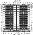
図2は、下部デッキボード3の内面、すなわち溶着面側から見た平面図であり、上部及び下部デッキボードは、図に示すように内面側に突出した複数の各種リブを備える。図3は図2のA-A線における断面図、図4は下部デッキボード3のフォーク差込領域に臨む桁側壁部近傍の構造を示す要部概略斜視図である。下部デッキボード3の平面形状は、概ね正方形であり、図中上下に位置する2辺3a,3b側からフォークリフト等のフォークが差し込まれる。そして、この正方形の下部デッキボード3の前記2辺3a,3bとは直交する2辺3c,3dに沿って、それぞれ端部桁部31,32が形成されており、これら端部桁部31,32と所定の距離をもって中央部に中央桁部33が形成されている。
前記端部桁部31,32や中央桁部33は、それぞれ外周部分に所定の高さの側壁34,35,36を有しており、これら側壁34,35,36で囲まれた部分が密閉空間となる。例えば、図中左端の端部桁部31は、下部デッキボード3の辺3cに沿った桁側壁部34a、フォーク挿入領域に沿った桁側壁部34b、フォーク差込側の2辺に沿った桁側壁部34c、及びフォーク差込口の寸法を拡大するために斜めに形成された桁側壁部34dを有しており、これらが連結されることにより略台形状の空間が形成される。同様に、図中右端の端部桁部32は、下部デッキボード3の辺3dに沿った桁側壁部35a、フォーク挿入領域に沿った桁側壁部35b、フォーク差込側の2辺に沿った桁側壁部35c、及びフォーク差込口の寸法を拡大し、フォークを差し込み易くするために斜め方向に形成された桁側壁部35dを有している。
中央桁部33は、前記端部桁部31,32の桁側壁部34b、35bとそれぞれ所定の間隔をもって平行に形成される桁側壁部36a,36b、フォーク差込側の2辺に沿った桁側壁部36c、及びフォーク差込口の寸法を拡大するために斜めに形成された桁側壁部36dを有しており、これらが連結されることで、下部デッキボード3の中央を貫通する細長い八角形状の空間が形成される。
以上の構成を有する端部桁部31,32や中央桁部33において、桁側壁部34b,35b,36a,36bがフォーク差込領域に臨む桁側壁部ということになる。
また、前記端部桁部31,32や、中央桁部33の側壁34,35,36で囲まれた領域には、フォーク差込方向とは直交する方向に連結リブ4が形成されている。これら連結リブ4は、対向する桁側壁部間を連結する形で形成されるものであり、例えば中央桁部33の場合、両側の桁側壁部36aと桁側壁部36bとを連結する形で形成されている。中央桁部33においては、前記連結リブ4の他、中央に連結リブ4と直交する中央リブ5も形成されている。なお、図3に示す通り、これら連結リブ4の高さは側壁34,35,36の高さと同等の高さを有しており、上部デッキボード及び下部デッキボードとを一体にする際に、桁や側壁とともに溶着される。
一方、端部桁部31,32と中央桁部33の間の領域には、フォーク差込方向にデッキボード端部同士を掛け渡すリブと、フォーク差込方向と垂直方向に隣り合う桁側壁部同士を掛け渡すリブと、で形成された格子状のリブ6が形成されている。これら格子状のリブ6のうち、前記連結リブ4と平行なリブ6の形成ピッチP1(形成間隔)は、前記連結リブ4の形成ピッチP2より小さい。すなわち、連結リブ4の形成ピッチP2は、リブ6の形成ピッチP1より大きい。本実施形態の場合、リブ6の形成ピッチP1は連結リブ4の形成ピッチP2の1/3であり、リブ6の形成数は連結リブ4の形成数の3倍である。
なお、連結リブ4の形成ピッチP2は、リブ6の形成ピッチP1の3倍であることに限られず、ピッチP1に対してピッチP2が大きくなればよく、例えば必ずしも等間隔である必要はないが、適宜任意の整数倍とすることができる。また、連結リブ4とピッチが一致するリブ6は、連結リブ4と連なる形で形成されていることが好ましいが、これに限られるわけではない。
このようにフォーク差込領域のリブ6の形成数を多くするのは、このフォーク差込領域に臨むリブ6にはフォークが直接接触するため、強度を確保する必要があるからである。また、曲げたわみを抑えるためにも、フォーク差込領域に臨むリブ6の形成数を多くすることが好ましい。さらに、リブ6の形成数を多くすることで、フォーク差込領域の上下面が擬似的に平面に近いものとなり、フォークの差し込みを円滑に行うことができる。
これに対して、端部桁部31,32や中央桁部33においては、桁内にフォークが侵入してくることはないため、耐衝撃強度についての要求は低い。さらに、端部桁部31,32や中央桁部33においては、周囲の側壁34,35,36が溶着されているため、連結リブ4の形成数が少なくても曲げたわみに対して十分に剛性を確保することができる。このように、端部桁部31,32や中央桁部33においては、連結リブ4の形成数が少なくても強度面で問題になることはなく、結果として連結リブ4の形成数を少なくすれば、樹脂製パレット1の重量増を抑えることができる。
また、フォーク差込領域においては、前記格子状のリブ6で囲まれた一領域(区画)毎に一定間隔で複数の小孔7が形成されている。本実施形態の場合、格子状のリブ6で囲まれた各領域に区画の長手方向に沿ってそれぞれ2つずつ小孔7が形成されているが、3つ以上形成することも可能である。小孔7は、フォーク差込方向に対して直行する方向に長い楕円または矩形形状である。この小孔7の形成も、樹脂製パレット1の重量増を極力抑えるための工夫であり、さらに格子状のリブ6間に貯まった雨水などの水抜き孔として機能する。その際、本実施形態のように一領域に対して複数の小孔を設ける場合には、軽量・高剛性を維持しつつ、水抜き機能を持たせることができるため、好ましい。一方、各領域に1つずつ設けた場合には、リブの増加による重量増、あるいは開口面積の増大による剛性の低下につながるため好ましくない。
以上が下部デッキボード3の概略構成であるが、本実施形態の樹脂製パレット1においては、強度向上を目的として、他にも様々な改良が施されている。以下、これら改良について説明する。
先ず、下部デッキボード3(及び上部デッキボード2)においては、フォーク差込領域に臨む桁側壁部34b,35b,36a,36bについても、耐衝撃強度を確保する必要がある。フォーク差込領域に臨む桁側壁部34b,35b,36a,36bには、フォーク先端の爪等が衝突する可能性があるからである。また、樹脂製パレット1の曲げ強度を確保する上でも、フォーク差込領域に臨む桁側壁部34b,35b,36a,36bの補強が必要である。
前記フォーク差込領域に臨む桁側壁部34b,35b,36a,36bの耐衝撃強度や曲げ強度等を高めるためには、連結リブ4の形成数をフォーク差込領域のリブ6と同程度に増やすことも考えられるが、その場合には、ある程度の重量増が避けられない。そこで、本実施形態の樹脂製パレット1では、フォーク差込領域に臨む桁側壁部34b,35b,36a,36bの内側壁面に沿って、略三角形状の補強リブ8を設置することで、耐衝撃強度等を高めるようにしている。
前記略三角形状の補強リブ8の形成位置は、隣接する連結リブ4と連結リブ4の間であり、本実施形態の場合、各連結リブ4間に、2つずつ補強リブ8を配置している。すなわち、連結リブ4間において、補強リブ8がフォーク差込領域のリブ6と同じピッチで形成されており、これら補強リブ8とリブ6とが桁側壁部34c,35c,36a,36bを挟んで対向し、桁側壁部34b,35b,36a,36bを両側から支持する形になっている。これにより、フォーク差込領域に臨む桁側壁部34b,35b,36a,36bの耐衝撃強度が大幅に向上するとともに、樹脂製パレット1の曲げ変形時に桁側壁部に発生する応力が分散され、曲げ強度も大きく向上する。
なお、隣接する連結リブ4間に形成する前記補強リブ8の数は、必ずしも2つでなくても良く、1つ、あるいは3以上であってもよい。ただし、十分な強度を確保するためには、2以上であることが好ましい。
前記補強リブ8は、側方から見た形状が略三角形であり、フォーク差込領域に臨む桁側壁部34b,35b,36a,36bの基端部近傍を支持する形で形成されている。ここで、補強リブ8の最大高さは、桁側壁部34c,35c,36a,36bの高さの1/2以下であり、本実施形態の場合、補強リブ8の最大高さがフォーク差込領域のリブ6の高さとほぼ同じである。補強リブ8の高さを抑えることで、補強リブ8を形成することによる重量増を最小限に抑えることができ、さらにパレットの剛性、曲げ強度を良好に保つことができる。
次に、前記端部桁部31,32及び中央桁部33について、フォーク差込領域に臨む桁側壁部34b,35b,36a,36bだけでなく、フォーク差込口F近傍の桁側壁部についても補強リブ9が設けられている。具体的には、フォーク差込口F近傍の桁側壁部34c,34d,35c,35d,36c,36dの内側に、これら桁側壁部34c,34d,35c,35d,36c,36dと同じ高さの補強リブ9が設置されている。
前記補強リブ9は、桁側壁部34c,34d,35c,35d,36c,36dと高さが同じであり、端部桁部31,32や中央桁部33と同じように、上部デッキボード2の補強リブ9と下部デッキボード3の補強リブ9とが突き合わされ、溶着等の手法で結合される。したがって、補強リブ9の設置による補強効果と、溶着面積の拡大による補強効果とが相俟って、フォーク差込側の桁側壁部34c,34d,35c,35d,36c,36dの耐衝撃強度が大きく向上し、例えばフォーク突き刺しによる破損等を防止することができる。なお、高さが低く、溶着されない場合には、パレットの高さ方向中央部分の強度が弱くなり、フォーク差し込み時にパレットが破損してしまう可能性が高くなる。
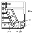
なお、前記補強リブ9は、他のリブ等からは独立した形で形成され、他のリブと接触しない大きさにて桁側壁部と垂直方向に突出して形成されている。さらに、フォーク差込口近傍の桁側壁部には、桁内部に設けられた桁側壁部に沿ったリブと桁側壁部と垂直なリブとから構成される複数の区画状のリブ10を有し、補強リブ9は、区画状のリブ10のそれぞれの区画内に1つずつ設けられている。すなわち、各桁部内において、フォーク差込口F近傍の桁側壁部34c,34d,35c,35d,36c,36d近傍領域を区画するリブ10等とは連結されておらず、これにより溶着面積の拡大等により十分な強度を確保することができるとともに、連結するための余分な部分を削ぎ落とすことで、重量増を抑えることができる。なお、補強リブ9は、必ずしも区画状のリブ10で区切られた区画内に対して1つずつである必要はなく、例えば、補強リブ9のみ独立して設けることも、区画内に複数の補強リブ9を用いることも可能である。
また、本実施形態の樹脂製パレット1においては、耐落下強度を向上させるため、4隅部分の補強も図られている。図5は下部デッキボード3の4隅部のうちの一カ所を拡大して示す平面図であり、隅部補強リブ11は、デッキボードの隅部底面に独立リブとして形成されている。この隅部補強リブ11は、側壁に対して略45°の方向に突出して設けられ、その他のリブ、例えば前記リブ10等とは連結していない。また、溶着面、すなわち桁側壁部等の高さよりも低い高さで形成された突起状リブである。
この隅部補強リブ11は、下部デッキボード3及び上部デッキボード2の4隅に位置してそれぞれ4カ所ずつ設けられており、樹脂製パレット1の4つの角部の強度を大きく向上している。例えば、樹脂製パレット1が落下した際に、側面や上面ではなく、角部から落下してしまうと、パレットが破損しやすい。そこで、本実施形態のように溶着面より低いリブを上下それぞれの4隅に設けることで、落下した際の破損を大幅に抑制することができる。また、隅部補強リブ11は、少なくとも溶着面より低い僅かな高さを有するリブである。ここで、隅部補強リブ11が、溶着面と略同一の高さであった場合には、角部からの落下時の破損に対して過剰スペックであるとともに重量増となるため、好ましくない。
さらに、下部デッキボード3や上部デッキボード2には、樹脂製パレット1を持ち運びの際に用いられる少なくとも小孔7より大きな開口面積を有する持ち手孔12が形成されている。持ち手孔12は、その開口した周囲を内側に凸になるように厚肉にすることにより、持ち運び時に自重により破損することがないよう強度の向上が図られている。また、さらなる強度向上のため、持ち手孔12から外側の区画には、小孔7が形成されていない。すなわち、前述の小孔7は、格子状のリブ6の区画内に水やゴミが溜まってしまうのを防止するために格子状のリブ6で形成されたそれぞれの区画内全てに形成することが好ましいが、この持ち手孔12の近傍領域に形成された区画の少なくとも一箇所のみは、小孔7が形成されていない。これにより持ち手孔12を用いてパレットを持ち上げる際に持ち手孔12近傍が破損、変形しないよう十分な強度を確保するようにしている。なお、近傍領域とは、少なくとも隣接する区画と、さらにその隣接する区画に隣接する区画をも含む。また、本実施形態においては、持ち手孔12から外側の区画に小孔7を形成していないが、少なくとも隣接する区画のいずれかが小孔のない構成であれば良く、持ち手孔12を囲む周囲全ての区画や持ち手孔から中央寄りの区画が小孔のない構成であっても良い。
図6は、下部デッキボード3の持ち手孔12近傍位置を拡大して示す図である。前述の通り、フォーク差込領域においては、狭いピッチでリブ6が格子状に形成されており、各格子(格子状のリブ6で区切られた区画領域)に2つの小孔7を形成することで、重量の削減を行っている。本実施形態の樹脂製パレット1では、持ち手孔12のいずれか一方の辺に隣接する格子内に小孔7を形成せず、持ち手孔12近傍の強度を確保するようにしている。これにより、手で持ち上げた際のデッキ面変形を回避することができる。
また、前記持ち手孔12近傍の小孔7が形成されていない区画は、リブ6に囲まれた閉鎖空間となり、例えば水やゴミ等が入り込んだ際に排除することが難しい。そこで、小孔7を形成されていない区画領域を取り囲むリブ6の少なくとも一部には、隣接する区画領域と連通するための切り欠き部6aが形成されている。なお、切り欠き部としては、区画領域を取り囲む一辺全てを設けない構成としても良いが、本実施形態のように一辺の一部分のみを切り欠いた形状にて構成しても良い。一辺全てを設けない構成とした場合には、小孔7が形成されていない区画領域内の水等を排除することは可能であるが、強度が著しく低下するため、一辺の一部分のみを切り欠いて隣接する区画領域に連通させ、隣接する小孔を水抜き孔として機能させることが好ましい。前記切り欠き部6aを形成することで、小孔7を形成しない格子内の水は、この切り欠き部6aを通して隣接する格子に移行する。隣接する格子には小孔7が設けられているので、この格子内の水は小孔7から速やかに排出される。
さらに、樹脂製パレット1は、端部の内壁から、フォーク差し込み入口の内壁に至る箇所に形成され、複数の仕切り壁により仕切られた複数の略矩形状の桁内密閉空間部と、前記桁内密閉空間部の周壁の一部同士及び/又は前記桁内密閉空間部の周壁の一部と桁の内壁をフォーク差し込み方向と垂直方向に橋渡しするように形成された桁内リブとを備えても良い。
ここで、端部桁部31において、複数の略矩形状の桁内密閉空間部とは、区画状のリブ10で区切られた複数の空間34eである。また、桁内密閉空間部の周壁の一部と桁の内壁をフォーク差し込み方向と垂直方向に橋渡しするように形成された桁内リブとは、複数の桁内密閉空間34eの周壁の一部34gと桁側壁部34aの内壁とを橋渡しする桁内リブ34fである。なお、本実施の形態では、桁内リブ34fは、複数の桁内密閉空間34eの周壁のうち、桁側壁部34dに対向する壁部34gの端部に設けられているが、壁部34gの途中から設けられていても良い。
また、端部桁部32において、複数の略矩形状の桁内密閉空間部とは、区画状のリブ10で区切られた複数の空間35eである。また、桁内密閉空間部の周壁の一部と桁の内壁をフォーク差し込み方向と垂直方向に橋渡しするように形成された桁内リブとは、複数の桁内密閉空間35eの周壁の一部35gと桁側壁部35aの内壁とを橋渡しする桁内リブ35fである。なお、本実施の形態では、桁内リブ35fは、複数の桁内密閉空間35eの周壁のうち、桁側壁部35dに対向する壁部35gの端部に設けられているが、壁部35gの途中から設けられていても良い。
また、中央桁部33において、複数の仕切り壁により仕切られた複数の略矩形状の桁内密閉空間部とは、区画状のリブ10で区切られた複数の空間36eである。また、複数の桁内密閉空間部36eの周壁の一部同士をフォーク差し込み方向と垂直方向に橋渡しするように形成された桁内リブとは、複数の桁内密閉空間36eの周壁の一部36g同士を橋渡しする桁内リブ36fである。
なお、本実施の形態では、桁内リブ34f,35f,36fは、複数の桁内密閉空間34e,35e,36eの周壁のうち、フォーク差込口Fから最も内側に形成されている桁内密閉空間の位置から設けられているが、その他の桁内密閉空間の位置から設けられても良い。また、桁内リブ34f,35f,36fは、桁側壁部34e,35e,36eに対向する壁部34g,35g,36gの端部から設けられているが、壁部34g,35g,36gの途中から設けられていても良い。
なお、桁内密閉空間部と桁内リブとで囲まれた領域R1は、桁内密閉空間部の領域よりも大きくなっている。また、桁内密閉空間部をそれぞれ区分けする仕切り壁、桁内密閉空間部の周壁の一部、及び、桁内リブ34f、35f、36fは、一続きのリブではなく、それぞれ個別に形成されている。また、仕切り壁は、桁の内壁面(34c,34d,35c,35d,36c,36d)に対して略垂直に形成されている。
これにより、フォークによって衝撃を受けやすいフォーク差し込み口に隣接する桁の端部の内部に桁の内部空間を分割するように比較的小さな密閉空間部を形成すると共に、この密閉空間部と桁の端部、及び密閉空間部同士を連結する補強リブを設けたことにより、樹脂製パレットの軽量化と曲げ強度の向上を図りながらも、衝撃を受けやすいフォーク差し込み口の補強及び桁の端部の衝撃強度を向上させることができ、これにより樹脂パレットの耐久性をより向上させることが可能となる。
また、フォークが当接しやすいフォーク差込口の入り口部付近に位置する桁のみに、他の部分と比較して密閉空間部を設けることにより補強したので、射出成型後の冷却過程における収縮差に起因する変形やひけを、最小限に抑えることができると共に、樹脂パレットの重量増加を抑制することができる。
さらに、樹脂パレット1は、2つのフォーク差込時におけるフォーク間の内側に近接する桁の周壁を、フォーク差込時におけるフォークの外側に近接する桁の周壁より肉厚に形成しても良い。たとえば、中央桁部33の周壁である桁側壁部36a,36b,36c,36dを、端部桁部31,32のフォーク挿入領域に沿った桁側壁部34b、35bよりも肉厚に形成する。具体的には、桁側壁部36a,36b,36c,36dを、桁側壁部34b、35bより1.5倍以上にすることが好ましい。これにより、軽量化のために中央桁部33の周壁36a,36b,36c,36dの厚みをも桁側壁部34b、35bと同様に薄肉に形成した場合に、発生するパレット使用時の反りを防止することが可能となる。
以上、本発明を適用した樹脂製パレットの実施形態について説明してきたが、前述の通り、本発明の樹脂製パレットにおいては、格子状に配置されたリブにより形成される区画内に、複数の小孔を設けるようにしているので、重量増を抑えつつ効果的に曲げ強度等を向上することが可能である。
なお、本発明が前述の実施形態に限定されるものでないことは言うまでもない。例えば、先の実施形態では、2方差しのパレットを例にして説明したが、例えば4方差しのパレットにも本発明を適用することは可能である。その他、例えば上部デッキボードや下部デッキボードの構造や形状等に関しても、本発明の要旨を逸脱しない範囲で、様々な変更が可能である。
1 樹脂製パレット
2 上部デッキボード
3 下部デッキボード
4 連結リブ
6 リブ
7 小孔
8 補強リブ
11 隅部補強リブ12 持ち手孔
31,32 端部桁部
33 中央桁部
34,35,36 側壁
34c,34d,35c,35d,36c,36d フォーク差込口近傍の桁側壁部
2 上部デッキボード
3 下部デッキボード
4 連結リブ
6 リブ
7 小孔
8 補強リブ
11 隅部補強リブ12 持ち手孔
31,32 端部桁部
33 中央桁部
34,35,36 側壁
34c,34d,35c,35d,36c,36d フォーク差込口近傍の桁側壁部
Claims (18)
- 格子状に配置されたリブにより形成される区画内に、複数の小孔が設けられていることを特徴とする樹脂製パレット。
- 各区画内に区画の長手方向に沿って2つの小孔が設けられていることを特徴とする請求項1記載の樹脂製パレット。
- 上部デッキボードと下部デッキボードを互いに対向させて溶着一体化してなる合成樹脂製パレットであって、
フォーク差込領域に形成される格子状のリブに囲まれた区画内に複数の小孔が設けられ、前記小孔はフォーク差込方向に対して直行する方向に長い楕円または矩形形状であることを特徴とする樹脂製パレット。 - 上部デッキボードと下部デッキボードとを桁部を介して結合してなり、前記桁部間の中空領域がフォーク差込領域とされてなる樹脂製パレットであって、
前記桁部及び前記フォーク差込領域には、それぞれフォーク差込方向と略直交する方向に所定の間隔でリブが設けられ、
前記桁部におけるリブの形成間隔が前記フォーク差込領域におけるリブの形成間隔よりも大きいことを特徴とする請求項1から3のいずれか1項記載の樹脂製パレット。 - 前記桁部におけるリブの形成間隔が前記フォーク差込領域におけるリブの形成間隔の整数倍であり、前記桁部におけるリブは、前記桁部を介して前記フォーク差込領域におけるリブに連なる形で形成されていることを特徴とする請求項4記載の樹脂製パレット。
- 上部デッキボードと下部デッキボードとを桁部を介して結合してなり、前記桁部間の中空領域がフォーク差込領域とされてなる樹脂製パレットであって、
前記桁部には、フォーク差込方向と略直交する方向に所定の間隔で桁部の側壁間を連結する連結リブが設けられるとともに、これら連結リブ間には、フォーク差込領域に臨む側壁の基端部を支持する略三角形状の補強リブが1以上設けられていることを特徴とする請求項1から5のいずれか1項記載の樹脂製パレット。 - 前記補強リブは、フォーク差込領域のリブと前記側壁を挟んで対向し、同じピッチで形成されていることを特徴とする請求項6記載の樹脂製パレット。
- 前記略三角形状の補強リブの最大高さが、前記桁側壁部の高さの1/2以下であることを特徴とする請求項6または7記載の樹脂製パレット。
- 前記略三角形状の補強リブの最大高さが、フォーク差込領域に形成されるリブの高さと略同一であることを特徴とする請求項6から8のいずれか1項記載の樹脂製パレット。
- 前記連結リブ間に前記略三角形状の補強リブが2以上設けられていることを特徴とする請求項6から9のいずれか1項記載の樹脂製パレット。
- 上部デッキボードと下部デッキボードとを桁部を介して結合してなり、前記桁部間の中空領域がフォーク差込領域とされてなる樹脂製パレットであって、
フォーク差込口近傍の桁壁の内面には、前記桁壁と垂直方向に突出した補強リブが形成されていることを特徴とする請求項1から10のいずれか1項記載の樹脂製パレット。 - 前記桁壁と垂直方向に突出した補強リブは、区画状のリブ内に設けられることを特徴とする請求項11記載の樹脂製パレット。
- 上部及び下部における4隅のうちの少なくとも1カ所に独立した補強リブが設けられていることを特徴とする請求項1から12のいずれか1項記載の樹脂製パレット。
- 前記上部及び下部における4隅のうちの少なくとも1カ所に独立した補強リブは、側壁に対して略45°の方向に突出して設けられていることを特徴とする請求項13記載の樹脂製パレット。
- 前記補強リブの高さは、溶着面よりも低いことを特徴とする請求項13または14記載の樹脂製パレット。
- 前記小孔と、
少なくとも前記小孔よりも大きな持ち手孔と、を備え、
前記持ち手孔近傍領域の区画のみに前記小孔が設けられていないことを特徴とする請求項1から15のいずれか1項記載の樹脂製パレット。 - 前記小孔が設けられていない区画を形成するリブの少なくとも1カ所に切り欠き部が設けられていることを特徴とする請求項16記載の樹脂製パレット。
- 前記切り欠き部は、区画を形成する一辺の一部分に形成されていることを特徴とする請求項17記載の樹脂製パレット。
Priority Applications (2)
| Application Number | Priority Date | Filing Date | Title |
|---|---|---|---|
| CN201380052614.8A CN104703888B (zh) | 2012-08-31 | 2013-08-27 | 树脂托盘 |
| JP2014533018A JP6299976B2 (ja) | 2012-08-31 | 2013-08-27 | 樹脂製パレット |
Applications Claiming Priority (16)
| Application Number | Priority Date | Filing Date | Title |
|---|---|---|---|
| JP2012191252 | 2012-08-31 | ||
| JP2012191254 | 2012-08-31 | ||
| JP2012-191254 | 2012-08-31 | ||
| JP2012-191252 | 2012-08-31 | ||
| JP2013-039056 | 2013-02-28 | ||
| JP2013-039042 | 2013-02-28 | ||
| JP2013-039035 | 2013-02-28 | ||
| JP2013-039063 | 2013-02-28 | ||
| JP2013039063 | 2013-02-28 | ||
| JP2013-039037 | 2013-02-28 | ||
| JP2013039042 | 2013-02-28 | ||
| JP2013039037 | 2013-02-28 | ||
| JP2013039035 | 2013-02-28 | ||
| JP2013039056 | 2013-02-28 | ||
| JP2013-039046 | 2013-02-28 | ||
| JP2013039046 | 2013-02-28 |
Publications (1)
| Publication Number | Publication Date |
|---|---|
| WO2014034660A1 true WO2014034660A1 (ja) | 2014-03-06 |
Family
ID=50183472
Family Applications (1)
| Application Number | Title | Priority Date | Filing Date |
|---|---|---|---|
| PCT/JP2013/072865 Ceased WO2014034660A1 (ja) | 2012-08-31 | 2013-08-27 | 樹脂製パレット |
Country Status (3)
| Country | Link |
|---|---|
| JP (1) | JP6299976B2 (ja) |
| CN (1) | CN104703888B (ja) |
| WO (1) | WO2014034660A1 (ja) |
Cited By (4)
| Publication number | Priority date | Publication date | Assignee | Title |
|---|---|---|---|---|
| JP2021075283A (ja) * | 2019-11-05 | 2021-05-20 | 日本プラパレット株式会社 | パレット |
| JP2021524829A (ja) * | 2018-05-31 | 2021-09-16 | シーエイチイーピー テクノロジー プロプライエタリー リミテッド | 上部デッキにカービングを備えた修理可能なプラスチックパレットおよび関連する方法 |
| JP2022507343A (ja) * | 2018-11-13 | 2022-01-18 | シーエイチイーピー テクノロジー プロプライエタリー リミテッド | デッキスクープ領域を備えるハーフサイズプラスチックパレット |
| JP2022135564A (ja) * | 2021-03-05 | 2022-09-15 | 三甲株式会社 | パレット |
Citations (5)
| Publication number | Priority date | Publication date | Assignee | Title |
|---|---|---|---|---|
| JP2002068189A (ja) * | 2000-08-29 | 2002-03-08 | Meiji Rubber & Chem Co Ltd | 合成樹脂製パレットとその製造方法 |
| JP2002516792A (ja) * | 1998-05-29 | 2002-06-11 | ゼネラル・エレクトリック・カンパニイ | 熱可塑性樹脂パレット |
| JP2004115065A (ja) * | 2002-09-26 | 2004-04-15 | Sanko Co Ltd | バッグ積載用合成樹脂製パレット |
| JP2004256137A (ja) * | 2003-02-25 | 2004-09-16 | Gifu Plast Ind Co Ltd | パレット |
| JP2008056303A (ja) * | 2006-08-31 | 2008-03-13 | Sanko Co Ltd | パレット |
Family Cites Families (3)
| Publication number | Priority date | Publication date | Assignee | Title |
|---|---|---|---|---|
| US6530476B1 (en) * | 1998-10-26 | 2003-03-11 | Rehrig Pacific Company | Pallet stacking device |
| US20080239904A1 (en) * | 2007-03-28 | 2008-10-02 | Minoru Yoshida | Method and apparatus for inspecting a surface of a specimen |
| CN102530353B (zh) * | 2010-09-30 | 2015-04-01 | 京洛株式会社 | 用于薄板面板的层叠的组件 |
-
2013
- 2013-08-27 CN CN201380052614.8A patent/CN104703888B/zh not_active Expired - Fee Related
- 2013-08-27 JP JP2014533018A patent/JP6299976B2/ja active Active
- 2013-08-27 WO PCT/JP2013/072865 patent/WO2014034660A1/ja not_active Ceased
Patent Citations (5)
| Publication number | Priority date | Publication date | Assignee | Title |
|---|---|---|---|---|
| JP2002516792A (ja) * | 1998-05-29 | 2002-06-11 | ゼネラル・エレクトリック・カンパニイ | 熱可塑性樹脂パレット |
| JP2002068189A (ja) * | 2000-08-29 | 2002-03-08 | Meiji Rubber & Chem Co Ltd | 合成樹脂製パレットとその製造方法 |
| JP2004115065A (ja) * | 2002-09-26 | 2004-04-15 | Sanko Co Ltd | バッグ積載用合成樹脂製パレット |
| JP2004256137A (ja) * | 2003-02-25 | 2004-09-16 | Gifu Plast Ind Co Ltd | パレット |
| JP2008056303A (ja) * | 2006-08-31 | 2008-03-13 | Sanko Co Ltd | パレット |
Cited By (10)
| Publication number | Priority date | Publication date | Assignee | Title |
|---|---|---|---|---|
| JP2021524829A (ja) * | 2018-05-31 | 2021-09-16 | シーエイチイーピー テクノロジー プロプライエタリー リミテッド | 上部デッキにカービングを備えた修理可能なプラスチックパレットおよび関連する方法 |
| US11305913B2 (en) | 2018-05-31 | 2022-04-19 | Chep Technology Pty Limited | Repairable plastic pallet with carvings in the top deck and associated methods |
| JP7258049B2 (ja) | 2018-05-31 | 2023-04-14 | シーエイチイーピー テクノロジー プロプライエタリー リミテッド | 上部デッキにカービングを備えた修理可能なプラスチックパレットおよび関連する方法 |
| US11787598B2 (en) | 2018-05-31 | 2023-10-17 | Chep Technology Pty Limited | Repairable plastic pallet with removable support blocks and associated methods |
| US12160489B2 (en) | 2018-05-31 | 2024-12-03 | Chep Technology Pty Limited | Repairable plastic pallet with removeable support blocks and associated methods |
| JP2022507343A (ja) * | 2018-11-13 | 2022-01-18 | シーエイチイーピー テクノロジー プロプライエタリー リミテッド | デッキスクープ領域を備えるハーフサイズプラスチックパレット |
| JP2021075283A (ja) * | 2019-11-05 | 2021-05-20 | 日本プラパレット株式会社 | パレット |
| JP7399455B2 (ja) | 2019-11-05 | 2023-12-18 | 日本プラパレット株式会社 | パレット |
| JP2022135564A (ja) * | 2021-03-05 | 2022-09-15 | 三甲株式会社 | パレット |
| JP7475691B2 (ja) | 2021-03-05 | 2024-04-30 | 三甲株式会社 | パレット |
Also Published As
| Publication number | Publication date |
|---|---|
| CN104703888A (zh) | 2015-06-10 |
| JP6299976B2 (ja) | 2018-03-28 |
| CN104703888B (zh) | 2018-04-06 |
| JPWO2014034660A1 (ja) | 2016-08-08 |
Similar Documents
| Publication | Publication Date | Title |
|---|---|---|
| JP6299976B2 (ja) | 樹脂製パレット | |
| US9586720B2 (en) | Pallet structure | |
| KR100729286B1 (ko) | 합성수지제 팰릿 | |
| KR20130126030A (ko) | 보강 조립구조를 갖는 화물적재용 팔레트 | |
| JP7382051B2 (ja) | パレット | |
| JP5118510B2 (ja) | 合成樹脂製のパレット | |
| JP4238154B2 (ja) | 合成樹脂製パレット | |
| JP5249734B2 (ja) | 合成樹脂製パレット | |
| JP4421496B2 (ja) | 合成樹脂製パレット | |
| JP5303512B2 (ja) | 合成樹脂製パレット | |
| JP4557255B2 (ja) | 合成樹脂製パレット | |
| JP7368828B2 (ja) | パレット | |
| JP6162039B2 (ja) | パレット | |
| JP6101301B2 (ja) | 角柱パイプを用いた支持棚 | |
| JP4326354B2 (ja) | 合成樹脂製パレット | |
| JP4866657B2 (ja) | 合成樹脂製パレット | |
| JP4340374B2 (ja) | 合成樹脂製パレット | |
| KR101363567B1 (ko) | 포장박스 조립구조를 갖는 화물적재용 팔레트 | |
| JP4991264B2 (ja) | パレット | |
| JP7073294B2 (ja) | 合成樹脂製パレット | |
| JP2011063305A (ja) | パレットボックス | |
| JP5627327B2 (ja) | パレット形成部材 | |
| JP4326359B2 (ja) | 合成樹脂製パレット | |
| JP2018122926A (ja) | パレット | |
| JP2026068514A (ja) | パレット |
Legal Events
| Date | Code | Title | Description |
|---|---|---|---|
| 121 | Ep: the epo has been informed by wipo that ep was designated in this application |
Ref document number: 13833546 Country of ref document: EP Kind code of ref document: A1 |
|
| ENP | Entry into the national phase |
Ref document number: 2014533018 Country of ref document: JP Kind code of ref document: A |
|
| NENP | Non-entry into the national phase |
Ref country code: DE |
|
| 122 | Ep: pct application non-entry in european phase |
Ref document number: 13833546 Country of ref document: EP Kind code of ref document: A1 |