WO2014034261A1 - ヒューズ - Google Patents
ヒューズ Download PDFInfo
- Publication number
- WO2014034261A1 WO2014034261A1 PCT/JP2013/068338 JP2013068338W WO2014034261A1 WO 2014034261 A1 WO2014034261 A1 WO 2014034261A1 JP 2013068338 W JP2013068338 W JP 2013068338W WO 2014034261 A1 WO2014034261 A1 WO 2014034261A1
- Authority
- WO
- WIPO (PCT)
- Prior art keywords
- melting point
- point metal
- wiring
- low melting
- fuse
- Prior art date
- Legal status (The legal status is an assumption and is not a legal conclusion. Google has not performed a legal analysis and makes no representation as to the accuracy of the status listed.)
- Ceased
Links
Images


Classifications
-
- H—ELECTRICITY
- H01—ELECTRIC ELEMENTS
- H01H—ELECTRIC SWITCHES; RELAYS; SELECTORS; EMERGENCY PROTECTIVE DEVICES
- H01H85/00—Protective devices in which the current flows through a part of fusible material and this current is interrupted by displacement of the fusible material when this current becomes excessive
- H01H85/02—Details
- H01H85/04—Fuses, i.e. expendable parts of the protective device, e.g. cartridges
- H01H85/041—Fuses, i.e. expendable parts of the protective device, e.g. cartridges characterised by the type
- H01H85/044—General constructions or structure of low voltage fuses, i.e. below 1000 V, or of fuses where the applicable voltage is not specified
- H01H85/045—General constructions or structure of low voltage fuses, i.e. below 1000 V, or of fuses where the applicable voltage is not specified cartridge type
-
- H—ELECTRICITY
- H01—ELECTRIC ELEMENTS
- H01H—ELECTRIC SWITCHES; RELAYS; SELECTORS; EMERGENCY PROTECTIVE DEVICES
- H01H85/00—Protective devices in which the current flows through a part of fusible material and this current is interrupted by displacement of the fusible material when this current becomes excessive
- H01H85/0039—Means for influencing the rupture process of the fusible element
- H01H85/0047—Heating means
-
- H—ELECTRICITY
- H01—ELECTRIC ELEMENTS
- H01H—ELECTRIC SWITCHES; RELAYS; SELECTORS; EMERGENCY PROTECTIVE DEVICES
- H01H85/00—Protective devices in which the current flows through a part of fusible material and this current is interrupted by displacement of the fusible material when this current becomes excessive
- H01H85/02—Details
- H01H85/04—Fuses, i.e. expendable parts of the protective device, e.g. cartridges
- H01H85/05—Component parts thereof
- H01H85/055—Fusible members
- H01H85/08—Fusible members characterised by the shape or form of the fusible member
- H01H85/11—Fusible members characterised by the shape or form of the fusible member with applied local area of a metal which, on melting, forms a eutectic with the main material of the fusible member, i.e. M-effect devices
-
- H—ELECTRICITY
- H01—ELECTRIC ELEMENTS
- H01H—ELECTRIC SWITCHES; RELAYS; SELECTORS; EMERGENCY PROTECTIVE DEVICES
- H01H85/00—Protective devices in which the current flows through a part of fusible material and this current is interrupted by displacement of the fusible material when this current becomes excessive
- H01H85/02—Details
- H01H85/46—Circuit arrangements not adapted to a particular application of the protective device
- H01H85/463—Circuit arrangements not adapted to a particular application of the protective device with printed circuit fuse
-
- H—ELECTRICITY
- H01—ELECTRIC ELEMENTS
- H01H—ELECTRIC SWITCHES; RELAYS; SELECTORS; EMERGENCY PROTECTIVE DEVICES
- H01H85/00—Protective devices in which the current flows through a part of fusible material and this current is interrupted by displacement of the fusible material when this current becomes excessive
- H01H85/02—Details
- H01H85/04—Fuses, i.e. expendable parts of the protective device, e.g. cartridges
- H01H85/05—Component parts thereof
- H01H85/055—Fusible members
- H01H85/08—Fusible members characterised by the shape or form of the fusible member
- H01H85/10—Fusible members characterised by the shape or form of the fusible member with constriction for localised fusing
Definitions
- the present invention relates to a fuse.
- Patent Document 1 describes a fuse element in which a low-melting-point metal is attached to a fused part of a wiring as an example of a fuse element.
- a fuse element in which a low-melting-point metal is attached to a fused part of a wiring as an example of a fuse element.
- An object of the present invention is to provide a fuse capable of reliably interrupting an overcurrent.
- the fuse according to the present invention includes an insulating substrate, wiring, a low melting point metal part, and a heating element.
- the wiring is arranged on one main surface of the insulating substrate.
- the low melting point metal part is provided on the wiring.
- the low melting point metal part has a lower melting point than the wiring.
- the low melting point metal part dissolves the wiring when it becomes a melt.
- the heating element heats the low melting point metal part. In plan view, the heating element is provided on the other side of the one end in the direction in which the wiring extends in the region where the low melting point metal portion is disposed.
- the heating element in the plan view, has the low melting point metal portion from the other side than the one end portion in the extending direction of the wiring in the region where the low melting point metal portion is arranged. It is provided over the other side rather than the other side end in the extending direction of the wiring in the arranged region.
- the wiring includes a fused part and a non-fused part.
- the fusing part is relatively easily blown by melting in the melt of the low melting point metal part.
- the non-blown part is located on one side of the fused part in the direction in which the wiring extends.
- the non-blown part is relatively difficult to blow.
- the heating element is arranged so as not to overlap the fusing part.
- the fusing portion is made of a metal having a relatively high melting rate with respect to the melt of the low melting point metal portion.
- the unmelted portion is made of a metal having a relatively low dissolution rate with respect to the melt of the low melting point metal portion.
- the fusing part includes at least one of Au and Ag.
- the non-blown part includes at least one of Cu, Pb, Ni, and Pt.
- the fused part is narrower than the non-fused part.
- the fused part is thinner than the non-fused part.
- the fuse further includes a liquid repellent portion.
- the liquid repellent portion is provided on one main surface of the insulating substrate on one side in the wiring extending direction with respect to the low melting point metal portion.
- the liquid repellent part repels the melt of the low melting point metal part.
- the heating element is provided on one main surface of the substrate or inside the substrate.
- the fuse further includes an insulating layer that insulates the wiring from the low melting point metal part.
- the low melting point metal portion is mainly composed of Sn.
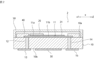
- FIG. 1 is a schematic cross-sectional view of a fuse in the first embodiment.
- FIG. 2 is a schematic cross-sectional view of a fuse in the second embodiment.
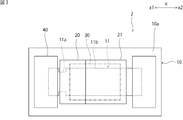
- FIG. 3 is a schematic plan view of a fuse in the second embodiment.
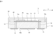
- FIG. 4 is a schematic cross-sectional view of a fuse in the third embodiment.
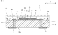
- FIG. 5 is a schematic cross-sectional view of a fuse in the fourth embodiment.
- FIG. 6 is a schematic cross-sectional view of a fuse in the fifth embodiment.
- FIG. 1 is a schematic cross-sectional view of a fuse in the first embodiment.
- the fuse 1 shown in FIG. 1 may be a passive element that automatically disconnects the wiring 11 when an overcurrent occurs in the wiring 11 described later, or detects the overcurrent and actively connects the wiring 11. It may be an active element that cuts off.
- the fuse 1 includes an insulating substrate 10.
- the insulating substrate 10 can be constituted by, for example, a ceramic substrate such as an alumina substrate, a resin substrate, or the like.
- the insulating substrate 10 may be a multilayer substrate having wiring inside.
- wiring 11 is arranged on the first main surface 10 a of the insulating substrate 10.
- One end of the wiring 11 is connected to a terminal electrode 13 disposed on the second main surface 10 b by a via hole electrode 12.
- the other end of the wiring 11 is connected to a terminal electrode 15 disposed on the second main surface 10b by a via hole electrode 14.
- the wiring 11 has a fusing part 11a and a non-fusing part 11b.
- the fusing part 11 a is a part that is relatively easily melted by melting in the melt of the low melting point metal part 20, and the non-melting part 11 b is relatively melted by melting in the melt of the low melting point metal part 20. It is a part that is difficult to melt.
- the fusing part 11a is made of a metal having a relatively high dissolution rate with respect to the melt of the low melting point metal part 20, and the non-melting part 11b is with respect to the melt of the low melting point metal part 20. It consists of a metal with a relatively low dissolution rate. More specifically, in the present embodiment, the fusing part 11a includes at least one of Au and Ag. It is preferable that the fusing part 11a is comprised with the alloy containing at least one of Ag, Au, or Ag and Au. In the present embodiment, the non-blown part 11b includes at least one of Cu, Pd, Ni, and Pt. The non-blown part 11b is preferably made of Cu, Pd, Ni, Pt, or an alloy containing at least one of Cu, Pd, Ni, and Pt.
- the low melting point metal part 20 is arranged on the wiring 11.
- the low melting point metal portion 20 has a melting point lower than that of the wiring 11 and is made of a low melting point metal that melts the wiring 11 when it becomes a melt.
- Specific examples of such low melting point metals include Sn alloys such as SnSb, SnCu, SnAg, SnAgCu, SnCuNi.
- an insulating layer 21 is disposed between the low melting point metal part 20 and the wiring 11.
- the insulating layer 21 electrically insulates the wiring 11 from the low melting point metal part 20.
- the terminal electrode 13 and the terminal electrode 15 are electrically connected by the via-hole electrodes 12 and 14 and the wiring 11, and no current flows through the low melting point metal part 20. Therefore, the wiring 11 tends to generate heat when an overcurrent occurs. Therefore, the fuse function of the fuse 1 is likely to be activated.
- the insulating layer 21 can electrically insulate the low melting point metal part 20 and the wiring 11 and can be removed by melting in the melt of the low melting point metal part 20 or volatilizing when the melt is generated. It is preferable that The insulating layer 21 can be made of, for example, rosin flux, organic acid flux, or the like.
- the fuse 1 is provided with a heating element 30 for heating the low melting point metal part 20. Therefore, the fuse 1 can function as a passive element or an active element.
- the heating element 30 can be constituted by, for example, a resistance heating element.
- the heating element 30 is disposed on the second main surface 10 b of the insulating substrate 10.
- the heating element 30 may be electrically connected to the terminal electrode 13 and the terminal electrode 15, for example. In that case, when an overcurrent flows through the wiring 11, the overcurrent also flows through the heating element 30 and the heating element 30 generates heat.
- the wiring 11 and the low melting point metal part 20 are covered with a sealing member 50 disposed on the insulating substrate 10.
- the fuse function of fuse 1 is expressed as follows.
- an overcurrent flows through the fuse 1, the wiring 11 generates heat.
- an overcurrent is detected by a detection mechanism (not shown), current is supplied to the heating element 30 and the heating element 30 generates heat.
- the low melting point metal part 20 is melted and a melt of the low melting point metal part 20 is generated.
- the wiring 11 is cut and the terminal electrode 13 and the terminal electrode 15 are electrically insulated.
- the fusing part 11 a is preferentially blown out of the wiring 11. Even after the melted part 11a is melted, at least a part of the non-fused part 11b remains.
- the melt of the low melting point metal part is conductive. For this reason, if the melt of the low melting point metal portion connects the remaining portions of the wiring, the fuse function does not appear.
- one end portion of the heating element 30 is provided so as to overlap a part of the low melting point metal portion 20 and the other end portion when the insulating substrate 10 is viewed in plan. .
- the center of the heating element 30 in the x-axis direction which is the direction in which the wiring material 11 extends, is located on the x2 side of the center of the low melting point metal part 20 in the x-axis direction.
- the heating element 30 is provided on the x2 side from the x1 side end in the x-axis direction, which is the direction in which the wiring member 11 extends, in the region where the low melting point metal part 20 is disposed. Therefore, since the melt of the low melting point metal part 20 flows toward a region where the temperature is higher, the melt of the low melting point metal part 20 tends to flow toward the x2 side. Therefore, the fuse function is surely exhibited and the overcurrent can be reliably interrupted.
- the heating element 30 is, in plan view, the x2-side from the x1-side end of the region where the low-melting-point metal part 20 is disposed. Therefore, it is more preferable that the low melting point metal portion 20 is provided over the x2 side rather than the x2 side end portion in the x-axis direction of the region where the low melting point metal portion 20 is disposed. Furthermore, it is preferable that the heating element 30 is arranged so as not to overlap the fusing part 11a in plan view. It is preferable that the heat generating body 30 is arranged on the x2 side from the fusing part 11a. Furthermore, the heating element 30 is preferably located on the x2 side with respect to the low melting point metal part 20.
- a liquid repellent part 40 is provided on the insulating substrate 10 on the x 1 side in the x-axis direction with respect to the low melting point metal part 20.
- the liquid repellent part 40 repels the melt of the low melting point metal part 20. For this reason, the melt of the low melting point metal part 20 is repelled to the x2 side by the liquid repellent part 40 and moves more smoothly to the x2 side.
- the liquid repellent portion 40 is preferably provided across the wiring 11 in the width direction of the wiring 11.
- the liquid repellent part 40 can be comprised by resin materials, such as glass materials, such as a borosilicate type glass, and an epoxy resin, for example. “Repel the melt” means that the contact angle is 90 ° or more.
- the fuse 1 of this embodiment exists as a single element, the fuse of the present invention may be incorporated in an electronic component.
- the fuse of the present invention may be integrated with a wiring board of an electronic component.
- FIG. 2 is a schematic cross-sectional view of a fuse in the second embodiment.
- FIG. 3 is a schematic plan view of a fuse in the second embodiment.
- FIG. 4 is a schematic cross-sectional view of a fuse in the third embodiment. In FIG. 3, drawing of the sealing member is omitted.
- the wiring 11 is composed of a single layer.
- the fusing part 11a is provided narrower than the non-fusing part 11b.
- the fusing part 11a is provided thinner than the non-fusing part 11b. Even in these cases, the melted part 11a is more easily melted into the melt of the low melting point metal part 20 than the non-fused part 11b.
- the wiring 11 is a single layer and does not have to have a narrow part or a thin part.
- the fusing part 11a of the wiring 11 is a part on which the low melting point metal part 20 is provided.
- the heating element 30 is located on the x2 side of the low melting point metal part 20 in plan view.
- FIG. 5 is a schematic cross-sectional view of a fuse in the fourth embodiment.
- FIG. 6 is a schematic cross-sectional view of a fuse in the fifth embodiment.
- the heating element 30 is provided on the first main surface 10 a of the insulating substrate 10.
- the low melting point metal part 20 and the heating element 30 are insulated by the insulating layer 60.
- the heating element 30 is provided inside the insulating substrate 10. In these cases, the heat of the heating element 30 is more easily supplied to the low melting point metal part 20 than when the heating element 30 is provided on the second main surface 10b. Therefore, the wiring 11 is easily melted.
Landscapes
- Fuses (AREA)
Description
図1は、第1の実施形態におけるヒューズの略図的断面図である。
図2は、第2の実施形態におけるヒューズの略図的図断面である。図3は、第2の実施形態におけるヒューズの略図的平面図である。図4は、第3の実施形態におけるヒューズの略図的断面図である。なお、図3においては、封止部材の描画を省略している。
図5は、第4の実施形態におけるヒューズの略図的断面図である。図6は、第5の実施形態におけるヒューズの略図的断面図である。
10…絶縁性基板
10a…第1の主面
10b…第2の主面
11…配線
11a…溶断部
11b…非溶断部
12,14…ビアホール電極
13,15…端子電極
20…低融点金属部
21…絶縁層
30…発熱体
40…撥液部
50…封止部材
60…絶縁層
Claims (11)
- 絶縁性基板と、
前記絶縁性基板の一主面上に配された配線と、
前記配線の上に設けられており、前記配線よりも低い融点を有するとともに、融液となった際に前記配線を溶解させる低融点金属部と、
前記低融点金属部を加熱する発熱体と、
を備え、
平面視において、前記発熱体は、前記低融点金属部が配された領域の前記配線の延びる方向における一方側端部よりも他方側に設けられている、ヒューズ。 - 平面視において、前記発熱体は、前記低融点金属部が配された領域の前記配線の延びる方向における一方側端部よりも他方側から、前記低融点金属部が配された領域の前記配線の延びる方向における他方側端部よりも他方側にわたって設けられている、請求項1に記載のヒューズ。
- 前記配線は、
前記低融点金属部の融液に融解することにより相対的に溶断されやすい溶断部と、
前記配線の延びる方向において前記溶断部の一方側に位置しており、相対的に溶断されにくい非溶断部と、
を含み、
平面視において、前記発熱体が、前記溶断部と重ならないように配されている、請求項1または2に記載のヒューズ。 - 前記溶断部は、前記低融点金属部の融液に対する溶解速度が相対的に高い金属からなり、
前記非溶断部は、前記低融点金属部の融液に対する溶解速度が相対的に低い金属からなる、請求項3に記載のヒューズ。 - 前記溶断部がAu及びAgの少なくとも一方を含み、
前記非溶断部がCu、Pb、Ni及びPtのうちの少なくとも一種を含む、請求項4に記載のヒューズ。 - 前記溶断部は、前記非溶断部よりも幅狭である、請求項3~5のいずれか一項に記載のヒューズ。
- 前記溶断部は、前記非溶断部よりも薄い、請求項3~6のいずれか一項に記載のヒューズ。
- 前記絶縁性基板の一主面上において、前記低融点金属部に対して、前記配線の延びる方向の一方側に設けられており、前記低融点金属部の融液をはじく撥液部をさらに備える、請求項1~7のいずれか一項に記載のヒューズ。
- 前記発熱体は、前記基板の一主面上または前記基板の内部に設けられている、請求項1~8のいずれか一項に記載のヒューズ。
- 前記配線と前記低融点金属部とを絶縁する絶縁層をさらに備える、請求項1~9のいずれか一項に記載のヒューズ。
- 前記低融点金属部は、Snを主成分とする、請求項1~10のいずれか一項に記載のヒューズ。
Priority Applications (3)
| Application Number | Priority Date | Filing Date | Title |
|---|---|---|---|
| KR1020157003463A KR20150029028A (ko) | 2012-08-29 | 2013-07-04 | 퓨즈 |
| CN201380043450.2A CN104584175A (zh) | 2012-08-29 | 2013-07-04 | 熔断器 |
| JP2014532859A JPWO2014034261A1 (ja) | 2012-08-29 | 2013-07-04 | ヒューズ |
Applications Claiming Priority (2)
| Application Number | Priority Date | Filing Date | Title |
|---|---|---|---|
| JP2012188351 | 2012-08-29 | ||
| JP2012-188351 | 2012-08-29 |
Publications (1)
| Publication Number | Publication Date |
|---|---|
| WO2014034261A1 true WO2014034261A1 (ja) | 2014-03-06 |
Family
ID=50183084
Family Applications (1)
| Application Number | Title | Priority Date | Filing Date |
|---|---|---|---|
| PCT/JP2013/068338 Ceased WO2014034261A1 (ja) | 2012-08-29 | 2013-07-04 | ヒューズ |
Country Status (5)
| Country | Link |
|---|---|
| JP (1) | JPWO2014034261A1 (ja) |
| KR (1) | KR20150029028A (ja) |
| CN (1) | CN104584175A (ja) |
| TW (1) | TW201409518A (ja) |
| WO (1) | WO2014034261A1 (ja) |
Cited By (1)
| Publication number | Priority date | Publication date | Assignee | Title |
|---|---|---|---|---|
| JP7142751B1 (ja) | 2021-07-05 | 2022-09-27 | 三菱電機株式会社 | 電力変換装置、及び遮断機構 |
Families Citing this family (2)
| Publication number | Priority date | Publication date | Assignee | Title |
|---|---|---|---|---|
| JP6739922B2 (ja) * | 2015-10-27 | 2020-08-12 | デクセリアルズ株式会社 | ヒューズ素子 |
| JP6452001B2 (ja) * | 2016-06-08 | 2019-01-16 | 株式会社村田製作所 | 電子装置、及び電子装置の製造方法 |
Citations (4)
| Publication number | Priority date | Publication date | Assignee | Title |
|---|---|---|---|---|
| JPS57113535A (en) * | 1980-11-27 | 1982-07-15 | Bitsukumannbueruke Gmbh | Electric fuse |
| JPH0538748U (ja) * | 1991-10-29 | 1993-05-25 | カルソニツク株式会社 | 自動車用空気調和装置の送風制御装置 |
| JP2000285777A (ja) * | 1999-03-31 | 2000-10-13 | Nec Kansai Ltd | 保護素子 |
| JP2004087467A (ja) * | 2002-06-28 | 2004-03-18 | Fujikura Ltd | 抵抗回路基板の温度ヒューズ |
Family Cites Families (2)
| Publication number | Priority date | Publication date | Assignee | Title |
|---|---|---|---|---|
| WO2007041529A2 (en) * | 2005-10-03 | 2007-04-12 | Littelfuse, Inc. | Fuse with cavity forming enclosure |
| CN201449830U (zh) * | 2009-06-19 | 2010-05-05 | 西安中熔电气有限公司 | 具有m效应点的熔断电阻器 |
-
2013
- 2013-07-04 CN CN201380043450.2A patent/CN104584175A/zh active Pending
- 2013-07-04 WO PCT/JP2013/068338 patent/WO2014034261A1/ja not_active Ceased
- 2013-07-04 JP JP2014532859A patent/JPWO2014034261A1/ja active Pending
- 2013-07-04 KR KR1020157003463A patent/KR20150029028A/ko not_active Ceased
- 2013-07-23 TW TW102126187A patent/TW201409518A/zh unknown
Patent Citations (4)
| Publication number | Priority date | Publication date | Assignee | Title |
|---|---|---|---|---|
| JPS57113535A (en) * | 1980-11-27 | 1982-07-15 | Bitsukumannbueruke Gmbh | Electric fuse |
| JPH0538748U (ja) * | 1991-10-29 | 1993-05-25 | カルソニツク株式会社 | 自動車用空気調和装置の送風制御装置 |
| JP2000285777A (ja) * | 1999-03-31 | 2000-10-13 | Nec Kansai Ltd | 保護素子 |
| JP2004087467A (ja) * | 2002-06-28 | 2004-03-18 | Fujikura Ltd | 抵抗回路基板の温度ヒューズ |
Cited By (2)
| Publication number | Priority date | Publication date | Assignee | Title |
|---|---|---|---|---|
| JP7142751B1 (ja) | 2021-07-05 | 2022-09-27 | 三菱電機株式会社 | 電力変換装置、及び遮断機構 |
| JP2023008013A (ja) * | 2021-07-05 | 2023-01-19 | 三菱電機株式会社 | 電力変換装置、及び遮断機構 |
Also Published As
| Publication number | Publication date |
|---|---|
| TW201409518A (zh) | 2014-03-01 |
| JPWO2014034261A1 (ja) | 2016-08-08 |
| KR20150029028A (ko) | 2015-03-17 |
| CN104584175A (zh) | 2015-04-29 |
Similar Documents
| Publication | Publication Date | Title |
|---|---|---|
| TWI390568B (zh) | Protection element | |
| JP2010522420A (ja) | 可融合金要素、可融合金要素を備えた温度ヒューズ、及び温度ヒューズの製造のための方法 | |
| JP5939311B2 (ja) | ヒューズ | |
| JP6389603B2 (ja) | スイッチ素子、スイッチ回路、及び警報回路 | |
| JP2010165685A (ja) | 保護素子及びバッテリーパック | |
| WO2014034261A1 (ja) | ヒューズ | |
| TWI493588B (zh) | fuse | |
| JP6171500B2 (ja) | ヒューズ | |
| JPH0412428A (ja) | ヒューズエレメント | |
| WO2014034262A1 (ja) | ヒューズ | |
| JP6102266B2 (ja) | ヒューズ | |
| JP2014044955A (ja) | 保護素子及びバッテリーパック | |
| TWI677002B (zh) | 開關元件 | |
| JP2012059719A (ja) | 保護素子及びバッテリーパック | |
| JP6622960B2 (ja) | スイッチ素子 | |
| JP6437221B2 (ja) | スイッチ素子、スイッチ回路及び警報回路 | |
| JP2020071935A (ja) | ヒューズ | |
| JP6615951B2 (ja) | スイッチ素子、スイッチ回路、及び警報回路 | |
| JP6142668B2 (ja) | ヒューズ素子 | |
| JP5994410B2 (ja) | 保護素子 | |
| JP2014235940A (ja) | ヒューズ素子 |
Legal Events
| Date | Code | Title | Description |
|---|---|---|---|
| 121 | Ep: the epo has been informed by wipo that ep was designated in this application |
Ref document number: 13832656 Country of ref document: EP Kind code of ref document: A1 |
|
| ENP | Entry into the national phase |
Ref document number: 2014532859 Country of ref document: JP Kind code of ref document: A |
|
| ENP | Entry into the national phase |
Ref document number: 20157003463 Country of ref document: KR Kind code of ref document: A |
|
| NENP | Non-entry into the national phase |
Ref country code: DE |
|
| 122 | Ep: pct application non-entry in european phase |
Ref document number: 13832656 Country of ref document: EP Kind code of ref document: A1 |