WO2014034150A1 - 浸炭部品 - Google Patents
浸炭部品 Download PDFInfo
- Publication number
- WO2014034150A1 WO2014034150A1 PCT/JP2013/005181 JP2013005181W WO2014034150A1 WO 2014034150 A1 WO2014034150 A1 WO 2014034150A1 JP 2013005181 W JP2013005181 W JP 2013005181W WO 2014034150 A1 WO2014034150 A1 WO 2014034150A1
- Authority
- WO
- WIPO (PCT)
- Prior art keywords
- surface layer
- cementite
- bending fatigue
- edge
- carburizing
- Prior art date
- Legal status (The legal status is an assumption and is not a legal conclusion. Google has not performed a legal analysis and makes no representation as to the accuracy of the status listed.)
- Ceased
Links
Images


Classifications
-
- C—CHEMISTRY; METALLURGY
- C21—METALLURGY OF IRON
- C21D—MODIFYING THE PHYSICAL STRUCTURE OF FERROUS METALS; GENERAL DEVICES FOR HEAT TREATMENT OF FERROUS OR NON-FERROUS METALS OR ALLOYS; MAKING METAL MALLEABLE, e.g. BY DECARBURISATION OR TEMPERING
- C21D1/00—General methods or devices for heat treatment, e.g. annealing, hardening, quenching or tempering
- C21D1/74—Methods of treatment in inert gas, controlled atmosphere, vacuum or pulverulent material
- C21D1/773—Methods of treatment in inert gas, controlled atmosphere, vacuum or pulverulent material under reduced pressure or vacuum
-
- C—CHEMISTRY; METALLURGY
- C21—METALLURGY OF IRON
- C21D—MODIFYING THE PHYSICAL STRUCTURE OF FERROUS METALS; GENERAL DEVICES FOR HEAT TREATMENT OF FERROUS OR NON-FERROUS METALS OR ALLOYS; MAKING METAL MALLEABLE, e.g. BY DECARBURISATION OR TEMPERING
- C21D1/00—General methods or devices for heat treatment, e.g. annealing, hardening, quenching or tempering
- C21D1/06—Surface hardening
-
- C—CHEMISTRY; METALLURGY
- C21—METALLURGY OF IRON
- C21D—MODIFYING THE PHYSICAL STRUCTURE OF FERROUS METALS; GENERAL DEVICES FOR HEAT TREATMENT OF FERROUS OR NON-FERROUS METALS OR ALLOYS; MAKING METAL MALLEABLE, e.g. BY DECARBURISATION OR TEMPERING
- C21D9/00—Heat treatment, e.g. annealing, hardening, quenching or tempering, adapted for particular articles; Furnaces therefor
- C21D9/32—Heat treatment, e.g. annealing, hardening, quenching or tempering, adapted for particular articles; Furnaces therefor for gear wheels, worm wheels, or the like
-
- C—CHEMISTRY; METALLURGY
- C22—METALLURGY; FERROUS OR NON-FERROUS ALLOYS; TREATMENT OF ALLOYS OR NON-FERROUS METALS
- C22C—ALLOYS
- C22C38/00—Ferrous alloys, e.g. steel alloys
- C22C38/001—Ferrous alloys, e.g. steel alloys containing N
-
- C—CHEMISTRY; METALLURGY
- C22—METALLURGY; FERROUS OR NON-FERROUS ALLOYS; TREATMENT OF ALLOYS OR NON-FERROUS METALS
- C22C—ALLOYS
- C22C38/00—Ferrous alloys, e.g. steel alloys
- C22C38/02—Ferrous alloys, e.g. steel alloys containing silicon
-
- C—CHEMISTRY; METALLURGY
- C22—METALLURGY; FERROUS OR NON-FERROUS ALLOYS; TREATMENT OF ALLOYS OR NON-FERROUS METALS
- C22C—ALLOYS
- C22C38/00—Ferrous alloys, e.g. steel alloys
- C22C38/04—Ferrous alloys, e.g. steel alloys containing manganese
-
- C—CHEMISTRY; METALLURGY
- C22—METALLURGY; FERROUS OR NON-FERROUS ALLOYS; TREATMENT OF ALLOYS OR NON-FERROUS METALS
- C22C—ALLOYS
- C22C38/00—Ferrous alloys, e.g. steel alloys
- C22C38/06—Ferrous alloys, e.g. steel alloys containing aluminium
-
- C—CHEMISTRY; METALLURGY
- C22—METALLURGY; FERROUS OR NON-FERROUS ALLOYS; TREATMENT OF ALLOYS OR NON-FERROUS METALS
- C22C—ALLOYS
- C22C38/00—Ferrous alloys, e.g. steel alloys
- C22C38/18—Ferrous alloys, e.g. steel alloys containing chromium
-
- C—CHEMISTRY; METALLURGY
- C22—METALLURGY; FERROUS OR NON-FERROUS ALLOYS; TREATMENT OF ALLOYS OR NON-FERROUS METALS
- C22C—ALLOYS
- C22C38/00—Ferrous alloys, e.g. steel alloys
- C22C38/18—Ferrous alloys, e.g. steel alloys containing chromium
- C22C38/22—Ferrous alloys, e.g. steel alloys containing chromium with molybdenum or tungsten
-
- C—CHEMISTRY; METALLURGY
- C22—METALLURGY; FERROUS OR NON-FERROUS ALLOYS; TREATMENT OF ALLOYS OR NON-FERROUS METALS
- C22C—ALLOYS
- C22C38/00—Ferrous alloys, e.g. steel alloys
- C22C38/18—Ferrous alloys, e.g. steel alloys containing chromium
- C22C38/40—Ferrous alloys, e.g. steel alloys containing chromium with nickel
- C22C38/42—Ferrous alloys, e.g. steel alloys containing chromium with nickel with copper
-
- C—CHEMISTRY; METALLURGY
- C22—METALLURGY; FERROUS OR NON-FERROUS ALLOYS; TREATMENT OF ALLOYS OR NON-FERROUS METALS
- C22C—ALLOYS
- C22C38/00—Ferrous alloys, e.g. steel alloys
- C22C38/18—Ferrous alloys, e.g. steel alloys containing chromium
- C22C38/40—Ferrous alloys, e.g. steel alloys containing chromium with nickel
- C22C38/44—Ferrous alloys, e.g. steel alloys containing chromium with nickel with molybdenum or tungsten
-
- C—CHEMISTRY; METALLURGY
- C22—METALLURGY; FERROUS OR NON-FERROUS ALLOYS; TREATMENT OF ALLOYS OR NON-FERROUS METALS
- C22C—ALLOYS
- C22C38/00—Ferrous alloys, e.g. steel alloys
- C22C38/18—Ferrous alloys, e.g. steel alloys containing chromium
- C22C38/40—Ferrous alloys, e.g. steel alloys containing chromium with nickel
- C22C38/58—Ferrous alloys, e.g. steel alloys containing chromium with nickel with more than 1.5% by weight of manganese
-
- C—CHEMISTRY; METALLURGY
- C23—COATING METALLIC MATERIAL; COATING MATERIAL WITH METALLIC MATERIAL; CHEMICAL SURFACE TREATMENT; DIFFUSION TREATMENT OF METALLIC MATERIAL; COATING BY VACUUM EVAPORATION, BY SPUTTERING, BY ION IMPLANTATION OR BY CHEMICAL VAPOUR DEPOSITION, IN GENERAL; INHIBITING CORROSION OF METALLIC MATERIAL OR INCRUSTATION IN GENERAL
- C23C—COATING METALLIC MATERIAL; COATING MATERIAL WITH METALLIC MATERIAL; SURFACE TREATMENT OF METALLIC MATERIAL BY DIFFUSION INTO THE SURFACE, BY CHEMICAL CONVERSION OR SUBSTITUTION; COATING BY VACUUM EVAPORATION, BY SPUTTERING, BY ION IMPLANTATION OR BY CHEMICAL VAPOUR DEPOSITION, IN GENERAL
- C23C8/00—Solid state diffusion of only non-metal elements into metallic material surfaces; Chemical surface treatment of metallic material by reaction of the surface with a reactive gas, leaving reaction products of surface material in the coating, e.g. conversion coatings, passivation of metals
- C23C8/06—Solid state diffusion of only non-metal elements into metallic material surfaces; Chemical surface treatment of metallic material by reaction of the surface with a reactive gas, leaving reaction products of surface material in the coating, e.g. conversion coatings, passivation of metals using gases
- C23C8/08—Solid state diffusion of only non-metal elements into metallic material surfaces; Chemical surface treatment of metallic material by reaction of the surface with a reactive gas, leaving reaction products of surface material in the coating, e.g. conversion coatings, passivation of metals using gases only one element being applied
- C23C8/20—Carburising
- C23C8/22—Carburising of ferrous surfaces
-
- C—CHEMISTRY; METALLURGY
- C21—METALLURGY OF IRON
- C21D—MODIFYING THE PHYSICAL STRUCTURE OF FERROUS METALS; GENERAL DEVICES FOR HEAT TREATMENT OF FERROUS OR NON-FERROUS METALS OR ALLOYS; MAKING METAL MALLEABLE, e.g. BY DECARBURISATION OR TEMPERING
- C21D6/00—Heat treatment of ferrous alloys
Definitions
- the present invention relates to a carburized part, and more particularly, to a carburized part manufactured by performing a vacuum carburizing process.
- a carburizing and quenching process may be performed as a surface hardening process on gears and belt type continuously variable transmission (CVT) pulleys used as automobile transmissions.
- CVT continuously variable transmission
- the carbon concentration in each part may vary.
- the carbon concentration in the edge portion including the corner portion is likely to be higher than that in the flat portion.
- Such a phenomenon that the carbon concentration becomes high is called excessive carburization.
- Coarse cementite tends to remain at the edge where excessive carburization has occurred.
- Coarse cementite is likely to be the starting point of cracking, so the bending fatigue strength of the edge portion may be reduced.
- Patent Document 1 Japanese Unexamined Patent Application Publication No. 2007-291486
- Patent Document 2 Japanese Unexamined Patent Application Publication No. 2006-349055
- Patent Document 3 Japanese Unexamined Patent Application Publication No. 2000-129418
- Patent Document 4 Japanese Unexamined Patent Application Publication No. 2000-129418
- Patent Document 5 Japanese Patent Application Laid-Open No. 2008-81781
- Patent Document 6 Japanese Patent Application Laid-Open No. 2009-57597 propose measures for improving the vacuum carburizing treatment.
- Patent Document 1 aims to suppress variations in the surface carbon concentration of almost the entire surface of the carburized part.
- the vacuum carburizing process disclosed in Patent Document 1 the vacuum carburizing process is performed under carburizing conditions in which the carbon concentration in the flat portion is in the range of 0.65 ⁇ 0.1 mass%. Thereafter, the carburized component is gradually cooled in the cooling gas. Thereafter, induction heating is performed on the carburized parts and water quenching is performed.
- Patent Document 2 aims to suppress excessive carburization at the edge portion.
- the chemical composition of the steel material is, by mass%, Si: 0.5 to 3.0%, Ni: 0.01 to 3.0%, Cu: 0.01 to It contains 1.00% and Cr: 0.3 to 1.0%, and satisfies [Si%] + [Ni%] + [Cu%] ⁇ [Cr%]> 0.5.
- the Si content is increased and the Cr content is decreased to suppress excessive carburization of the edge portion.
- Patent Document 3 proposes a gear in which the difference in surface carbon concentration between the face portion and the corner portion of the gear is reduced even when the vacuum carburizing process is performed.
- chamfering is performed on a stress concentration portion located in the vicinity of the tooth root, and then vacuum carburization is performed.
- Patent Document 4 aims to suppress the occurrence of uneven carburization.
- the steel part is cooled to the Ar3 transformation point or less. Thereafter, the steel part is reheated to the austenitizing temperature range and quenched.
- the cooling rate during the cooling is 2 ° C./second.
- Patent Document 5 aims to improve the coarsening of crystal grains and obtain an object to be processed having predetermined physical property values.
- the temperature of the workpiece (workpiece) is lowered from a first temperature to a predetermined temperature between the diffusion step and the quenching step (normalizing step).
- the object to be processed is held at a predetermined temperature.
- the temperature of the workpiece is raised to the second temperature.
- the cooling rate during the normalizing process is 1.5 ° C./second.
- Patent document 6 aims at providing the gearwheel which suppressed the residue of coarse cementite and improved pitching resistance.
- the chemical composition of gears is C: 0.10 to 0.30%, Si: 1.0 to 1.5%, Mn: 0.20 to 1.5%, Cr: 0% by mass. .31% or less, Mo: 0.1 to 1.0%, with the balance being Fe and inevitable impurities.
- the gear is heated to a point Ac 3 or higher to perform a vacuum carburizing process to form a carburized layer having a carbon concentration of 1% by mass or more on the surface layer of the gear. Thereafter, the gear is cooled to a temperature not higher than the Ar1 point.
- the bending fatigue strength may be low. Moreover, if the Si content is too high or the Cr content is too low as in the chemical composition disclosed in Patent Document 2, the bending fatigue strength may be lowered. Further, chamfering in the vicinity of the tooth root as disclosed in Patent Document 3 is very difficult. Furthermore, even when chamfering is performed, the bending fatigue strength may be low. Furthermore, when the vacuum carburization process of patent document 4 and patent document 5 is implemented, cementite may become coarse and bending fatigue strength may be low.
- the gear of Patent Document 6 may have low bending fatigue strength because the Si content is too high.
- An object of the present invention is to provide a carburized part manufactured by performing a vacuum carburizing process and having excellent bending fatigue strength at an edge part and a flat part.
- the carburized component according to the present embodiment is manufactured by performing a vacuum carburizing process on a steel material.
- the surface of the carburized component includes an apex portion, an edge portion, and a flat portion.
- the vertex portion includes a vertex formed by three or more surfaces and a surface portion within 1 mm from the vertex.
- the edge portion is an area OA (a portion OA () of a portion overlapping with an imaginary circle having a radius of 1 mm centering on the side in a cross section perpendicular to the side, in a surface portion within 1 mm from the side of the surface and within 1 mm from the top.
- mm 2 and the surface length SL (mm) of the carburized component at the overlapping portion are the surface portions that satisfy the formula (1).
- a flat part is surface parts other than a vertex part and an edge part among the said surfaces.
- the steel materials are in mass%, C: 0.10 to 0.30%, Si: 0.05 to 0.8%, Mn: 0.3 to 2.0%, P: 0.06% or less, S: 0.006 to 0.1%, Cr: 0.5 to 3.0%, Al: 0.01 to 0.1%, and N: 0.025% or less, Cu: 0 to 0.5%, Ni: 0 to 0.5% and Mo: 0 to 1.0% are contained, and the balance is composed of Fe and impurities.
- the carbon concentration in the flat surface layer part from the flat part to a depth of 0.05 mm is 0.7% or more and less than 1.0% in mass%.
- the length of cementite in the edge surface layer portion from the edge portion to a depth of 80 ⁇ m is 3.0 ⁇ m or less.
- the cementite fraction of the edge surface layer is 5 to 15%.
- the carburized parts according to the present embodiment are excellent in the bending fatigue strength of the edge part and the flat part.
- FIG. 1 is a perspective view of a carburized component according to the present embodiment.
- FIG. 2 is a cross-sectional view of the carburized component in FIG.
- FIG. 3 is a perspective view of a tooth portion of a gear that is an example of a carburized component.
- FIG. 4 is a diagram showing the relationship between the length of cementite in the edge surface layer portion of the carburized part in FIG. 1 and the four-point bending fatigue strength.
- FIG. 5 is a diagram showing the relationship between the carbon concentration of the flat surface layer portion of the carburized component in FIG. 1 and the Ono-type rotary bending fatigue strength.
- FIG. 6 is a schematic diagram showing a processing pattern of vacuum carburization processing and quenching processing according to the present embodiment.
- FIG. 7 is a side view of the Ono-type rotating bending test piece used in the example.
- the apex portion On the surface of the carburized part, the apex portion includes an apex formed by three or more surfaces and a surface portion within 1 mm from the apex.
- the edge portion on the surface of the carburized part is defined as follows. Of the surface of the carburized part, attention is paid to a surface portion other than the apex portion (that is, more than 1 mm away from the apex) and within 1 mm from the side of the surface. This surface portion is referred to as an “edge surface portion”.
- a cross section that includes an arbitrary point on the side of the edge surface portion and is perpendicular to the side is assumed.
- a virtual circle having a radius of 1 mm centered on a point on the side of the carburized part is assumed.
- FI (mm) is defined by the following formula.
- FI area OA (mm 2 ) of the cross-sectional portion overlapping with the virtual circle / surface length SL (mm) of the cross-sectional portion overlapping with the virtual circle
- edge surface portion a surface portion satisfying the following formula (1) is defined as an “edge portion”.
- FI OA / SL ⁇ 0.7 (1)
- the part other than the apex part and the edge part is defined as “flat part”.
- the part is a flat part.
- the carburized component 100 is a four-point bend specimen as shown in FIG.
- a surface portion edge surface portion
- 1 mm from the apex 10 and within 1 mm from the side 2 of the cutout portion are further than 1 mm from the apex 10 and within 1 mm from the side 2 of the cutout portion.
- point Pc An arbitrary point on the side 2 in the edge surface portion is defined as “point Pc”.
- the point Pc is located on a side that is more than 1 mm away from the vertex 10 formed by three or more surfaces.
- FIG. 1 a cross section CS perpendicular to the side at the point Pc is assumed.
- FIG. 2 is a schematic diagram of a cross section CS.
- a virtual circle VC having a radius of 1 mm centered on the corner point Pc is assumed.
- an area overlapping with the virtual circle VC centered on the point Pc is defined as a partial area Ac.
- the area OA (mm 2 ) of the partial region Ac is obtained.
- the area OA of the partial region Ac ⁇ / 4 (mm 2 ).
- the surface length SL (mm) in the partial region Ac is obtained.
- the partial area Ac has two sides with the point Pc as a vertex on the surface.
- a portion within 1 mm from a side constituted by a set of a plurality of points satisfying the expression (1) among the edge surface portions can be defined as an edge portion.
- the vertex 1 in FIG. 1 includes a vertex formed by three surfaces and a surface portion within 1 mm from the vertex.
- a surface portion other than the vertex portion and the edge portion is defined as a “flat portion” (reference numeral 3 in FIG. 1).
- FIG. 3 is a perspective view of the vicinity of the gear teeth, which is an example of a carburized component.
- the gear may be an external gear or an internal gear.
- the tooth tip has four vertex portions including the vertex 10.
- the side 2 extends from the vertex 10 toward the tooth bottom.
- Side 2 is curved at the root. Attention is paid to an edge surface portion that is farther than 1 mm from the vertex 10 and within 1 mm from the side 2.
- the expression (1) is satisfied. Therefore, the edge surface portion including the point Pc is an edge portion.
- a region within 1 mm from the side portion constituted by the points satisfying the expression (1) corresponds to the “edge portion”.
- the four apex portions and the surface portion other than the edge portions correspond to the flat portion 3.
- the apex portion, the flat portion, and the edge portion can be divided on the surface of the carburized component.
- the edge surface layer portion Since the carbon concentration is high in the surface layer portion (called the edge surface layer portion) including the edge portion where excessive carburization has occurred, cementite is likely to precipitate and grow and become coarse. Coarse cementite tends to be the starting point of cracking. Therefore, the bending fatigue strength is reduced particularly in the edge surface layer portion of the carburized component.
- FIG. 4 is a diagram showing the relationship between the length ( ⁇ m) of cementite in the edge surface layer portion of the carburized part and the 4-point bending fatigue strength (MPa).
- FIG. 4 is based on the results obtained by the four-point bending fatigue test described in Examples described later.
- Each point in the region 200 in FIG. 4 is a test result when the length of cementite in the edge surface layer is 5.0 ⁇ m or more.
- the 4-point bending fatigue strength is an index of the bending fatigue strength of the edge surface layer portion of the carburized parts.
- the edge surface layer portion is defined as a range from the edge portion to a depth of 80 ⁇ m. Referring to FIG. 4, when the cementite length at the edge surface layer portion is 3.0 ⁇ m or less, the cementite length at the edge surface layer portion exceeds 3.0 ⁇ m (in the case of the region 200 point). As a result, the 4-point bending fatigue strength is remarkably increased. Therefore, by refining the cementite in the edge surface layer portion, the bending fatigue strength of the edge surface layer portion of the carburized component increases.
- SEM scanning electron microscope
- FIG. 5 is a diagram showing the relationship between the carbon concentration (%) of the flat surface layer portion and the Ono-type rotary bending fatigue strength (MPa).
- FIG. 5 is based on the result obtained by the Ono type
- the Ono type rotating bending fatigue strength is an index of the bending fatigue strength of the flat surface layer. Referring to FIG. 5, when the carbon concentration of the flat surface layer portion is 0.7% or more, the bending fatigue strength is remarkably increased as compared with the case where the carbon concentration of the flat surface layer portion is less than 0.7%. . Therefore, the bending fatigue strength of the flat surface layer portion can be increased by setting the carbon concentration of the flat surface layer portion to 0.7% or more and less than 1.0%.
- the cooling rate of the carburized parts is set to 3.5 ° C./second or more. By setting this cooling rate, the structure of the carburized component is transformed to form pearlite, bainite, or martensite.
- the carburized parts are reheated and quenched.
- the quenching temperature is lowered to 800 to 900 ° C.
- the microstructure of the edge surface layer portion is pearlite or bainite
- the cementite in the steel starts to dissolve during reheating, and the cementite is divided. Therefore, fine cementite is formed at the edge portion.
- the microstructure of the edge portion is martensite, the martensite is transformed and fine cementite is generated.
- the cooling rate after the diffusion step is set to 3.5 ° C./second or more, and further, the quenching temperature in the quenching step is set to 800 to 900 ° C., thereby suppressing the formation of coarse cementite and the edge surface layer portion.
- the length of the cementite becomes 3.0 ⁇ m or less.
- the cementite fraction of the edge surface layer portion is an appropriate amount based on the cooling rate.
- the carburized component according to the present embodiment is manufactured by performing a vacuum carburizing process on a steel material.
- the steel material has the following chemical composition.
- C 0.10 to 0.30% Carbon (C) increases the strength of the core of the carburized component. If the C content is too low, the above effect cannot be obtained effectively. On the other hand, if the C content is too high, the strength of the steel material after hot working (hot rolling, hot forging, etc.) becomes excessively high, and the machinability decreases. Therefore, the C content is 0.10 to 0.30%.
- the minimum with preferable C content is higher than 0.10%, More preferably, it is 0.12%, More preferably, it is 0.15%, More preferably, it is 0.17%.
- the upper limit with preferable C content is less than 0.30%, More preferably, it is 0.26%, More preferably, it is 0.24%.
- Si 0.05 to 0.8% Silicon (Si) increases the hardenability and temper softening resistance of the steel, and increases bending fatigue strength and surface fatigue strength. If the Si content is too low, the above effect cannot be obtained effectively. On the other hand, if the Si content is too high, precipitation of cementite in the excessive carburized portion of the steel material after the carburizing treatment is suppressed, and the carbon concentration of the matrix increases. As a result, the bending fatigue strength of the steel material decreases. Therefore, the Si content is 0.05 to 0.8%.
- the minimum with preferable Si content is higher than 0.05%, More preferably, it is 0.1%, More preferably, it is 0.15%.
- the upper limit with preferable Si content is less than 0.8%, More preferably, it is 0.55%, More preferably, it is 0.35%.
- Mn 0.3 to 2.0%
- Manganese (Mn) increases the hardenability and temper softening resistance of the steel, and increases the bending fatigue strength. If the Mn content is too low, the above effect cannot be obtained effectively. On the other hand, if the Mn content is too high, the strength of the steel material after hot working becomes excessively high, and the machinability decreases. Therefore, the Mn content is 0.3 to 2.0%.
- the minimum with preferable Mn content is higher than 0.3%, More preferably, it is 0.4%, More preferably, it is 0.5%.
- the upper limit with preferable Mn content is less than 2.0%, More preferably, it is 1.5%, More preferably, it is 1.1%.
- Phosphorus (P) is an impurity. P segregates at the grain boundary and embrittles the grain boundary. Therefore, P reduces the bending fatigue strength and surface fatigue strength of steel materials.
- the P content is preferably as low as possible. Therefore, the P content is 0.06% or less.
- the preferable P content is less than 0.06%, and more preferably 0.03% or less.
- S 0.006 to 0.1%
- Sulfur (S) combines with Mn to form MnS and enhances the machinability of the steel material. If the S content is too low, the above effect is difficult to obtain. On the other hand, if the S content is too high, coarse MnS is formed, and the bending fatigue strength and surface fatigue strength of the steel material are reduced. Therefore, the S content is 0.006 to 0.1%.
- the minimum with preferable S content is higher than 0.006%, More preferably, it is 0.01%.
- the upper limit with preferable S content is less than 0.1%, More preferably, it is 0.06%, More preferably, it is 0.03%.
- Chromium (Cr) increases the hardenability and temper softening resistance of the steel material, and increases the bending fatigue strength and surface fatigue strength of the steel material. Cr further promotes the precipitation of fine cementite. If the Cr content is too low, the above effect is difficult to obtain. On the other hand, if the Cr content is too high, the edge surface layer portion of the carburized component is excessively carburized during high temperature carburizing. Furthermore, the strength of the steel material after hot working (hot rolling and hot forging) becomes excessively high, and the machinability decreases. Therefore, the Cr content is 0.5 to 3.0%.
- the minimum with preferable Cr content is higher than 0.5%, More preferably, it is 1.0%.
- the upper limit with preferable Cr content is less than 3.0%, More preferably, it is 2.5%, More preferably, it is 2.0%.
- Al 0.01 to 0.1%
- Aluminum (Al) deoxidizes steel. Further, Al combines with N (nitrogen) to form AlN, and the crystal grains are refined. If the Al content is too low, the above effect is difficult to obtain. On the other hand, if the Al content is too high, hard oxide inclusions are likely to be generated. These oxide inclusions reduce the bending fatigue strength of the steel material. Therefore, the Al content is 0.01 to 0.1%.
- the minimum with preferable Al content is higher than 0.01%, More preferably, it is 0.02%.
- the upper limit with preferable Al content is less than 0.1%, More preferably, it is 0.05%, More preferably, it is 0.04%.
- Al content in this specification is content of acid-soluble Al (sol.Al).
- N 0.025% or less Nitrogen (N) is inevitably contained in the steel. N combines with Al to form AlN and refines the crystal grains. However, if the N content is too high, the hot forgeability and impact characteristics of the steel material are degraded. Therefore, the N content is 0.025% or less.
- the minimum with preferable N content is 0.010%, More preferably, it is 0.014%.
- the upper limit with preferable N content is less than 0.025%, More preferably, it is 0.020%, More preferably, it is 0.018%.
- the balance of the steel material of this embodiment is Fe and impurities.
- the impurities referred to here refer to ores and scraps used as a raw material for steel materials, or elements mixed in from the environment of the manufacturing process.
- the steel material according to the present embodiment may further contain one or more selected from the group consisting of Cu and Ni instead of part of Fe. These elements are arbitrary elements. All of these elements suppress excessive carburization of steel materials and increase toughness.
- Cu 0 to 0.5%
- Copper (Cu) is an optional element.
- Cu suppresses excessive carburization of the steel material and further increases the toughness of the steel material. If Cu is contained even a little, the above effect can be obtained to some extent. On the other hand, if Cu content is too high, the hot workability of steel materials will fall. Therefore, the Cu content is 0 to 0.5%. If the Cu content is 0.1% or more, the above effects are remarkably obtained.
- the upper limit with preferable Cu content is less than 0.5%, More preferably, it is 0.3%.
- Nickel (Ni) is an optional element. Ni suppresses excessive carburization of the steel material and further increases the toughness of the steel material. If Ni is contained even a little, the above effect can be obtained to some extent. On the other hand, if the Ni content is too high, the manufacturing cost of the steel material increases. Therefore, the Ni content is 0 to 0.5%. If the Ni content is 0.1% or more, the above effects are remarkably obtained. The upper limit with preferable Ni content is less than 0.5%, More preferably, it is 0.2%.
- the steel material according to the present embodiment may further contain Mo instead of a part of Fe.
- Mo is an optional element.
- Mo 0 to 1.0% Molybdenum (Mo) increases the hardenability and temper softening resistance of the steel, and increases the bending fatigue strength and surface fatigue strength of the steel. If Mo is contained even a little, the above effect can be obtained to some extent. On the other hand, if the Mo content is too high, the strength of the steel material after hot working becomes too high, and the machinability of the steel material decreases. Therefore, the Mo content is 0 to 1.0%. If the Mo content is 0.03% or more, the above-described effect is remarkably obtained.
- the minimum with preferable Mo content is 0.06%, More preferably, it is 0.10%.
- the upper limit with preferable Mo content is less than 0.5%, More preferably, it is 0.36%.
- the carburized component according to the present embodiment is manufactured by subjecting a steel material having the above chemical composition to vacuum carburization.
- the carburized component includes a vertex portion, a flat portion, and an edge portion that are classified according to the above definition. For example, even when the carburized component is a gear or a pulley, the carburized component includes a vertex portion, a flat portion, and an edge portion based on the above definition.
- Carbon concentration in the flat surface layer of carburized parts The carbon concentration in the surface layer portion (flat surface layer portion) from the flat portion to a depth of 0.05 mm is 0.7% or more and less than 1.0% in mass%.
- the carbon concentration in the flat surface layer is measured by the following method.
- a flat surface layer portion is cut out by cutting or the like, and the carbon concentration is quantified using the chips.
- the carbon concentration in the flat surface layer portion is analyzed by EPMA (electron beam microanalyzer).
- the carbon concentration in the flat surface layer portion is 0.7% or more and less than 1.0%.
- the preferable lower limit of the carbon concentration of the flat surface layer portion is higher than 0.7%, and more preferably 0.73%.
- the upper limit with preferable carbon concentration of a flat surface layer part is 0.9%, More preferably, it is 0.86%.
- the carbon concentration of the flat surface layer portion can be made 0.7% or more and less than 1.0% by adjusting the vacuum carburizing conditions.
- the carbon concentration in the flat surface layer portion is 0.7% or more and less than 1.0%, the bending fatigue strength of the flat surface layer portion is increased.
- the edge surface layer portion of the carburized component 100 contains a plurality of cementites.
- the length of cementite in the edge surface layer in the range from the edge to the depth of 80 ⁇ m is 3.0 ⁇ m or less.
- the length of cementite in the edge surface layer is measured by the following method.
- the edge part in the cross section CS is corroded with a night or the like. Thereafter, a range (edge surface layer portion) from the edge portion to a depth of 80 ⁇ m is observed.
- a scanning electron microscope (SEM) with a magnification set to 2000 times is used. Within the above range, the longest cementite is identified and its length is measured. Among the distances between any two points on the interface of each cementite, the maximum distance is defined as the length of the cementite.
- Coarse cementite becomes the starting point of fatigue fracture and reduces the bending fatigue strength of the edge surface layer of carburized parts. However, if the length of the cementite is small, that is, if the cementite is fine, the cementite is unlikely to become a starting point for fatigue fracture. If the length of the cementite is 3.0 ⁇ m or less, the cementite is sufficiently fine, so that the bending fatigue strength of the edge surface layer portion is increased.
- cementite fraction of edge surface layer The cementite fraction of the edge surface layer is 5 to 15%.
- the cementite fraction can be determined based on the above definition.
- the cementite fraction in the edge surface layer is 5% or more, the amount of cementite deposited is sufficiently large. Therefore, the carbon concentration in the matrix is sufficiently low, and the decrease in bending fatigue strength is suppressed.
- the upper limit of the cementite fraction does not particularly affect the bending fatigue strength. However, in the case of the chemical composition of the present embodiment, the cementite fraction at the edge surface layer portion hardly exceeds 15%. Therefore, the upper limit of the cementite fraction at the edge surface layer is 15%. A preferable lower limit of the cementite fraction is 5%.
- molten steel having the above chemical composition is manufactured, and a slab (slab or bloom) is manufactured by continuous casting using the molten steel.
- a billet (steel piece) is manufactured by hot working a slab or an ingot. The billet is hot worked to produce a steel bar or wire. The hot working may be hot rolling or hot forging.
- the manufactured steel bar or wire is cold forged or machined to produce a steel material having a predetermined shape including an apex portion, a flat portion, and an edge portion.
- the machining is, for example, cutting or drilling, and the top, flat portion, and edge portion are formed by a known method.
- ⁇ Vacuum carburizing treatment is performed on the manufactured steel. Furthermore, after the vacuum carburizing process, the steel material is reheated and a quenching process is performed. By performing the vacuum carburizing treatment and the quenching treatment, the carbon concentration of the flat surface layer portion becomes 0.7% or more and less than 1.0%. Further, fine cementite is deposited on the edge surface layer, and an appropriate cementite fraction can be obtained.
- the vacuum carburizing process and the quenching process will be described in detail.
- FIG. 6 shows a processing pattern example of the vacuum carburizing process and the quenching process in the present embodiment.
- the left vertical axis and solid line graph in the figure show the heat treatment temperature (carburizing temperature and quenching temperature).
- the right vertical axis and the broken line graph indicate the furnace pressure.
- the horizontal axis indicates time.
- the vacuum carburization process includes a heating step S1, a soaking step S2, a carburizing step S3, a diffusion step S4, and a cooling step S5.
- the heating step S1 the steel material charged in the furnace is heated to the carburizing temperature Ts (° C.).
- the soaking step S2 the steel material is soaked at the carburizing temperature Ts.
- the carburizing step S3, the steel material is carburized after the soaking step.
- carbon that has entered the steel after the carburizing step is diffused in the steel.
- the cooling step S5 the steel material after the diffusion step is cooled to 500 ° C. or less at a cooling rate Vc (° C./second).
- the carburizing step S3 and the diffusion step S4 may be repeated twice or more. For example, after performing the carburizing step S3 and the diffusion step S4, the carburizing step S3 may be performed again, and then the diffusion step S4 may be performed. Further, each of the carburizing step S3 and the diffusion step S4 may be performed only once.
- Nitrogen gas may be introduced while evacuating to about 1 Torr (about 133 Pa).
- convection heating may be performed in a nitrogen atmosphere of 100 to 700 hPa. In the case of convection heating, the rate of temperature rise can be increased.
- the furnace pressure Pref in FIG. 6 is below atmospheric pressure.
- a hydrocarbon gas is introduced into the furnace, the inside of the furnace is set to a predetermined gas pressure (carburizing gas pressure) Ps (kPa), Carburizing treatment is performed. Further, in the diffusion step S4, the inside of the furnace is decompressed and returned to a substantially vacuum (Pv).
- Carburizing temperature Ts 980-1200 ° C
- the carburizing temperature Ts is preferably higher in order to increase the solid solubility of carbon at the edge portion after the carburizing step S3 and the diffusion step S4. If the carburizing temperature Ts is too low, the solid solubility of carbon at the edge portion becomes low, and coarse cementite precipitates. On the other hand, if the carburizing temperature Ts is too high, the above effects are saturated and the heating cost is increased. Therefore, the carburizing temperature Ts is 980 to 1200 ° C.
- the minimum with the preferable carburizing temperature Ts is higher than 980 degreeC, More preferably, it is 1000 degreeC, More preferably, it is 1020 degreeC.
- the upper limit with preferable carburizing temperature Ts is lower than 1200 degreeC, More preferably, it is 1100 degreeC, More preferably, it is 1050 degreeC.
- Carburizing gas pressure Ps 10 kPa or less
- the carburizing gas is a hydrocarbon gas.
- the hydrocarbon gas is, for example, acetylene, propane, ethylene or the like. If the carburizing gas pressure Ps is too high, soot is likely to be generated in the furnace. Therefore, the carburizing gas pressure Ps is 10 kPa or less. A preferable carburizing gas pressure Ps is 1 kPa or less.
- Cooling rate Vc 3.5 ° C./second or more If the cooling rate Vc in the cooling step S5 is too small, cementite in the edge surface layer portion is difficult to be refined, and the length of cementite may exceed 3.0 ⁇ m. Therefore, the cooling rate Vc is 3.5 ° C./second or more.
- the cooling rate Vc here means the cooling rate (° C./second) of the surface temperature of the steel material. More specifically, in the cooling step S5, the average cooling rate from the carburizing temperature Ts to 500 ° C. ( ° C / sec).
- gas cooling is performed in the cooling step S5.
- the cooling gas is, for example, nitrogen.
- the cooling rate is 3.5 ° C./second or more, the cooling may be performed by another cooling method.
- a preferable cooling rate is 4 ° C./second or more, more preferably 5 ° C./second or more. In this case, cementite is further refined.
- Cooling stop temperature Tcs 500 ° C. or lower
- the steel material is preferably cooled to 500 ° C. or lower. That is, the cooling stop temperature Tcs is set to 500 ° C. or lower. Thereby, the steel structure of an edge part transforms and cementite precipitates.
- the cooling stop temperature Tcs may be normal temperature (25 ° C.). In short, the cooling stop temperature Tcs is not particularly limited as long as the cementite precipitates.
- the cooling method after cooling to the cooling stop temperature Tcs at the above cooling rate is not particularly limited. It may be allowed to cool or may be another cooling method.
- the time TIS of the carburizing step S3 and the time TID of the diffusion step S4 are set by, for example, a vacuum carburizing simulation.
- the vacuum carburization simulation is performed by the following method, for example.
- the following diffusion equation based on Fick's second law is solved using the difference method, and the carbon concentration distribution of each part of the steel material after the vacuum carburizing heat treatment is obtained.
- D represents a diffusion constant
- t time (sec)
- C represents carbon concentration (mass%).
- the above diffusion equation is a diffusion equation in austenite of carbon.
- the carburizing process time TIS, the diffusion process time TID, and the carburizing temperature Ts (however, so that the carbon concentration of the flat surface layer portion is 0.7% or more and less than 1.0%.
- the carburizing temperature Ts is determined from 980 to 1200 ° C.).
- the diffusion equation is solved based on a predetermined carburizing process time TIS, diffusion process time TID, and carburizing temperature Ts, and the carbon concentration of the flat surface layer portion is obtained. If the carbon concentration is within a range of 0.7% or more and less than 1.0%, an actual vacuum carburizing process is performed at a predetermined carburizing process time TIS, diffusion process time TID, and carburizing temperature Ts.
- the carburization process time TIS, the diffusion process time TID, and the carburization temperature Ts are changed, the diffusion equation is solved again, and the carbon concentration of the flat surface layer part is obtained.
- the solution of the diffusion equation is obtained until the carbon concentration in the flat surface layer portion is 0.7% or more and less than 1.0%, and the carburizing process time TIS, the diffusion process time TID, and the carburizing temperature Ts are determined.
- the vacuum carburizing treatment test was actually repeatedly performed using a steel material for a carburized part having a desired shape, and the carbon concentration in the flat surface layer portion was 0.7% or more and 1.0%.
- the carburizing process time TIS, the diffusion process time TID, and the carburizing temperature Ts may be determined.
- the carburizing process time TIS, the diffusion process time TID, and the carburizing temperature Ts may be determined by performing both the vacuum carburizing simulation and the actual vacuum carburizing treatment test. For example, when the carbon concentration of the flat surface layer portion is 0.75% as a result of actually performing the vacuum carburizing process under the condition that the carbon concentration of the flat surface layer portion is 0.80% in the vacuum carburization simulation result, May be corrected based on the result of the actual vacuum carburizing process.
- conditions that make the carbon concentration of the flat surface layer within the above range are determined by a vacuum carburization simulation and / or a preliminary test using an actual machine. And the vacuum carburizing process is implemented using the determined conditions. Thereby, the carbon concentration of a flat surface layer part can be 0.7% or more and less than 1.0%.
- the quenching temperature Tq is 800 to 900 ° C.
- the quenching temperature here means the surface temperature of the carburized component. That is, in the quenching process, the surface temperature of the carburized component is maintained at 800 to 900 ° C.
- the preferable holding time at the quenching temperature is 10 minutes or more.
- the steel material After holding the steel material at the quenching temperature Tq for the holding time, the steel material is quenched. At this time, the steel material may be water-cooled and quenched, or oil-cooled and quenched. In addition, you may implement a tempering process after hardening.
- the carburized part according to the present embodiment is manufactured.
- a plurality of carburized parts were manufactured using a plurality of steel materials having various chemical compositions.
- the bending fatigue strength of the manufactured carburized parts was investigated.
- the bending fatigue strength of the edge surface layer portion and the flat surface layer portion was evaluated by the following method.
- the bending fatigue strength of the edge surface layer was evaluated based on the results of a four-point bending fatigue test. Specifically, a carburized part was manufactured by performing a vacuum carburizing process and a quenching process, which will be described later, on a four-point bending fatigue test piece including a flat part and an edge part. A four-point bending fatigue test was performed using the manufactured four-point bending fatigue test piece, and the obtained bending fatigue strength was used as an index of the bending fatigue strength of the edge surface layer portion.
- the bending fatigue strength of the flat surface layer portion was evaluated based on the Ono type rotary bending test results.
- the Ono type rotating bending fatigue test piece a large stress is applied to the notch bottom. There is no edge portion at the bottom of the notch, and there is a flat portion. Therefore, the bending fatigue strength of the flat portion was evaluated by the Ono type rotating bending fatigue test.
- a plurality of 4-point bending fatigue test pieces having the shape shown in FIG. 1 were collected from the manufactured round bar.
- the four-point bending fatigue test piece was 13 mm in height and width, and 100 mm in length.
- a notch having a semicircular cross section was formed in the center of the length. The radius of the notch was 2 mm.
- FIG. 7 An Ono-type rotating bending fatigue test piece shown in FIG. 7 was collected from R / 2 part of the manufactured round bar.
- the R / 2 portion is a portion that bisects the center and the outer periphery of the round bar cross section (circular shape).
- the shape of the rotating bending fatigue test piece conformed to JIS Z2274 (1974).
- Each numerical value in FIG. 7 indicates a dimension (unit: mm).
- condition I in Table 2 vacuum carburizing, quenching and tempering were performed under the following conditions.
- the test piece was soaked at the carburizing temperature Ts (° C.) shown in Table 2 for 60 minutes.
- Carburizing process S3 was implemented after implementing soaking process S2.
- Table 2 shows the carburizing process time TIS (min) and the carburizing gas pressure Ps (kPa) during the carburizing process.
- a diffusion step S4 was performed.
- the diffusion process time TID (min) was as shown in Table 2.
- gas cooling was performed to 500 ° C. at a cooling rate Vc shown in Table 2. Nitrogen gas was used as the cooling gas. Gas cooling continued even after the temperature became 500 ° C. or lower, and cooling was continued until the total gas cooling time reached 20 minutes. After the gas cooling time of 20 minutes passed, the cooling was stopped.
- each test piece was quenched and tempered under the following conditions.
- the steel was again heated to the quenching temperature Tq (see Table 2).
- the atmosphere in the furnace at this time was nitrogen gas.
- Tq quenching temperature
- the steel was quenched with oil.
- the steel was tempered.
- the tempering temperature was 170 ° C., and the holding time at the tempering temperature was 2 hours.
- condition II in Table 2 vacuum carburizing, quenching and tempering were performed under the following conditions.
- soaking step S2 soaking was performed at a carburizing temperature Ts of 950 ° C. for 60 minutes.
- Carburizing process S3 was implemented after implementing soaking process S2.
- the carburizing process time TIS (min) and carburizing gas pressure Pv (kPa) were as shown in Table 2.
- a diffusion step S4 was performed.
- the diffusion process time TID (min) was as shown in Table 2.
- Each of the carburizing step S3 and the diffusion step S4 was performed once.
- the steel material was furnace cooled (slowly cooled) to 860 ° C. Therefore, gas cooling was not performed in condition II.
- the steel material was soaked at 860 ° C. for 30 minutes and subjected to oil quenching. After quenching, the steel was tempered.
- the tempering temperature was 170 ° C., and the holding time at the tempering temperature was 2 hours.
- test piece (a plurality of four-point bending fatigue test pieces and a plurality of Ono-type rotating bending fatigue test pieces for each test number) that were vacuum carburized by the above process was manufactured.
- each test number is flat using one 4-point bending fatigue test piece and one Ono-type rotary bending fatigue test piece for each test number.
- the carbon concentration in the surface layer was measured.
- the carbon concentration Cc (%) of the flat surface layer portion was measured by an EPMA (electron beam microanalyzer) in the flat portion including the point Pf shown in FIG.
- the carbon concentration Cc (%) of the flat surface layer portion was measured with an EPMA (electron beam microanalyzer) in a partial region including an arbitrary point of the groove bottom of the annular semicircular groove of the Ono type rotating bending fatigue test piece.
- EPMA electron beam microanalyzer
- the “Cc (%)” column in the “4-point bending SP” column indicates the carbon concentration (%) of the flat surface layer portion of the 4-point bending fatigue test piece
- [4-point bending fatigue test] Among a plurality of 4-point bending fatigue test pieces of each test number, carburized parts of other 4-point bending fatigue test pieces that were not used for the carbon concentration measurement test of the flat surface layer portion and the structure observation test of the edge surface layer portion were used. A four-point bending fatigue test was conducted. A servo type fatigue tester was used for the test. The distance between the fulcrums of the 4-point bending fatigue test piece was 45 mm. The maximum load stress was 1373 MPa, and the stress ratio between the maximum load stress and the minimum load stress was 0.1. The frequency was 10 Hz. The breaking strength when the number of repeated stress loads was 1 ⁇ 10 4 was evaluated as 4-point bending fatigue strength FS4 (MPa).
- Ono type rotating bending fatigue test Conforms to JIS Z2274 (1974) with respect to other Ono type rotating bending fatigue test pieces that were not used in the carbon concentration measurement test of the flat surface layer portion among the plurality of Ono type rotating bending fatigue test pieces of each test number. Then, the Ono type rotating bending fatigue test was carried out at room temperature (25 ° C.) and in the air under the conditions of a rotational speed of 3400 rpm. The maximum stress (MPa) that did not break when the number of repeated stress additions was 1 ⁇ 10 7 was defined as Ono-type rotary bending fatigue strength FSo (MPa).
- the chemical composition of the carburized parts with test numbers 1 to 13 is appropriate, and the carburizing temperature Ts (° C), carburizing gas pressure Ps (kPa), cooling rate Vc (° C / sec) and quenching temperature Tq (° C) are also appropriate.
- the carbon concentration in the flat part of each test piece was also within the range of 0.7% or more and less than 1.0%. Therefore, the cementite length Lce of the edge surface layer portion of the carburized parts (4-point bending fatigue test pieces) of test numbers 1 to 13 was within 3.0 ⁇ m, and the cementite fraction Rce was 5% or more. Therefore, the 4-point bending fatigue strength FS4, which is an index of the bending fatigue strength of the edge portion, was as high as 850 MPa or more. Furthermore, the Ono-type rotary bending fatigue strength FSo, which is an index of the bending fatigue strength of the flat portion, was also as high as 520 MPa or more.
- test numbers 14, 15, and 20 the carburizing temperature Ts was too low, and the cementite length Lce of the edge surface layer portion exceeded 5 ⁇ m. Therefore, the 4-point bending fatigue strength FS4 of test numbers 14, 15, and 20 was low.
- the carburizing process time TIS and / or the diffusion process time TID were inappropriate. Specifically, the carburizing time of test number 16 was shorter than test number 1. Similarly, the carburizing process time TIS of test number 17 was shorter than test number 2, and the carburizing process time TIS of test number 18 was shorter than test number 3. Therefore, the carbon concentration in the flat surface layer portions of test numbers 16 to 18 was less than 0.7%. As a result, the bending fatigue strength obtained by the Ono type rotating bending fatigue test was less than 520 MPa, and the bending fatigue strength FSo of the flat portion was low. Further, in test numbers 16 to 18, the carbon concentration in the flat surface layer portion was too low, and therefore no excessive carburization occurred in the edge surface layer portion. Therefore, cementite did not precipitate on the edge surface layer.
- the gas cooling rate Vc in the vacuum carburizing process was less than 3.5 ° C./second. Therefore, coarse cementite was deposited on the edge surface layer, and the length Lce of the cementite exceeded 5 ⁇ m. Therefore, the 4-point bending fatigue strength FS4 was low.
- test number 24 the quenching temperature Tq was too high. Therefore, a lot of cementite at the edge portion was dissolved, and the cementite fraction Rce was low. Therefore, the 4-point bending fatigue strength FS4 was low.
- the quenching temperature Tq was too low. Therefore, the cementite at the edge portion did not dissolve and was not divided. Therefore, the length Lce of cementite exceeded 3.0 ⁇ m, and the 4-point bending fatigue strength FS4 was low.
Landscapes
- Chemical & Material Sciences (AREA)
- Engineering & Computer Science (AREA)
- Materials Engineering (AREA)
- Mechanical Engineering (AREA)
- Metallurgy (AREA)
- Organic Chemistry (AREA)
- Physics & Mathematics (AREA)
- Thermal Sciences (AREA)
- Crystallography & Structural Chemistry (AREA)
- Chemical Kinetics & Catalysis (AREA)
- Heat Treatment Of Articles (AREA)
- Solid-Phase Diffusion Into Metallic Material Surfaces (AREA)
Abstract
真空浸炭処理を実施して製造され、エッジ部及び平坦部の曲げ疲労強度に優れた浸炭部品を提供する。本実施形態の浸炭部品は、鋼材に対して真空浸炭処理を実施して製造される。浸炭部品の表面は、頂点部と、エッジ部と、平坦部とを含む。鋼材は、質量%で、C:0.10~0.30%、Si:0.05~0.8%、Mn:0.3~2.0%、P:0.06%以下、S:0.006~0.1%、Cr:0.5~3.0%、Al:0.01~0.1%、N:0.025%以下、Cu:0~0.5%、Ni:0~0.5%、及び、Mo:0~1.0%を含有し、残部はFe及び不純物からなる。平坦部から0.05mmの深さまでの平坦表層部における炭素濃度は、質量%で、0.7%以上1.0%未満であり、エッジ部から80μmの深さまでのエッジ表層部は、3.0μm以下の長さを有する1又は複数のセメンタイトを含有し、エッジ部のセメンタイト分率は5~15%である。
Description
本発明は、浸炭部品に関し、さらに詳しくは、真空浸炭処理を実施することにより製造される浸炭部品に関する。
機械部品の曲げ疲労強度や耐摩耗性を向上するために、機械部品に対して表面硬化処理が実施される。たとえば、自動車の変速機として使用される歯車やベルト式無段変速機(CVT)用プーリでは、表面硬化処理として、浸炭焼入れ処理が実施される場合がある。
浸炭焼入れ処理として、従来、ガス浸炭焼入れ処理が多く利用されている。しかしながら、最近では、真空浸炭焼入れ処理が普及し始めている。真空浸炭焼入れ処理では、ガス浸炭焼入れ処理よりも減圧された雰囲気内で、炭化水素ガスを用いて浸炭処理を実施する。真空浸炭焼入れ処理では、真空炉と同じ構造の熱処理炉を利用する。そのため、ガス浸炭焼入れ処理と比較して、浸炭温度を高くすることができ、処理時間を短くすることができる。また、減圧下で浸炭処理するため、粒界酸化が抑制され、高い疲労強度が得られやすい。さらに、炭素収率が高いため、炭酸ガスの排出量を抑えることができる。
しかしながら、真空浸炭処理により製造された浸炭部品では、各部での炭素濃度がばらつく場合がある。特に、コーナ角部を含むエッジ部の炭素濃度は、平坦部と比較して高くなりやすい。このように、炭素濃度が高くなる現象を過剰浸炭という。過剰浸炭が発生したエッジ部では、粗大なセメンタイトが残存しやすい。粗大なセメンタイトは割れの起点となりやすいため、エッジ部の曲げ疲労強度が低下する場合がある。
国際公開第2009/131202号(特許文献1)、特開2007-291486号公報(特許文献2)、特開2006-349055号公報(特許文献3)、特開2000-129418号公報(特許文献4)、特開2008-81781号公報(特許文献5)及び特開2009-57597号公報(特許文献6)は、真空浸炭処理の改善策を提案する。
具体的には、特許文献1は、浸炭部品のほぼ全面の表面炭素濃度のばらつきを抑えることを目的とする。特許文献1に開示された真空浸炭処理では、平坦部の炭素濃度が0.65±0.1質量%の範囲内となる浸炭条件で、真空浸炭処理を実施する。その後、浸炭部品を冷却ガス中において徐冷する。その後、浸炭部品に対して高周波加熱を実施し、水焼入れを実施する。
特許文献2は、エッジ部における過剰浸炭を抑制することを目的とする。特許文献2に開示された真空浸炭処理では、鋼材の化学組成が、質量%で、Si:0.5~3.0%、Ni:0.01~3.0%、Cu:0.01~1.00%及びCr:0.3~1.0%を含有し、[Si%]+[Ni%]+[Cu%]-[Cr%]>0.5を満たす。要するに、特許文献2では、Si含有量を高くし、Cr含有量を低くして、エッジ部の過剰浸炭を抑制する。
特許文献3は、真空浸炭処理を実施しても、歯車の面部と角部とにおける表面炭素濃度の差異が小さくなる歯車を提案する。特許文献3では、歯元近傍に位置する応力集中部分に対して面取り加工を実施し、その後、真空浸炭処理を実施する。
特許文献4は、浸炭むらの発生を抑制することを目的とする。特許文献4では、真空浸炭処理を実施した後、Ar3変態点以下まで鋼部品を冷却する。その後、オーステナイト化温度域まで鋼部品を再加熱して、焼入れを実施する。特許文献4の図2では、上記冷却時の冷却速度は2℃/秒である。
特許文献5は、結晶粒の粗大化を改善して所定の物性値を有する被処理物を得ることを目的とする。特許文献5では、拡散工程と焼入れ工程との間において、被処理物(workpiece)の温度を第1の温度から所定温度まで降下させる(焼ならし工程)。次に、被処理物を所定温度に保持する。その後、被処理物の温度を第2の温度まで上昇させる。特許文献5の図4及び図6では、焼ならし工程時における冷却速度は1.5℃/秒である。
特許文献6は、粗大なセメンタイトの残留を抑制して耐ピッチング性を高めた歯車を提供することを目的とする。特許文献6では、歯車の化学組成は、質量%でC:0.10~0.30%、Si:1.0~1.5%、Mn:0.20~1.5%、Cr:0.31%以下、Mo:0.1~1.0%を含有し、残部はFe及び不可避的不純物からなる。上記歯車をAc3点以上に加熱して真空浸炭処理を実施して、歯車の表層に1質量%以上の炭素濃度を有する浸炭層を形成する。その後、歯車をAr1点以下の温度に冷却する。
しかしながら、特許文献1の真空浸炭処理で製造された浸炭部品の炭素濃度は低いため、曲げ疲労強度が低い場合がある。また、特許文献2に開示された化学組成のように、Si含有量が高すぎたり、Cr含有量が低すぎたりすれば、曲げ疲労強度が低くなる場合がある。また、特許文献3に開示されたような、歯元近傍の面取り加工は非常に困難である。さらに、面取り加工を実施した場合であっても、曲げ疲労強度が低い場合がある。
さらに、特許文献4及び特許文献5の真空浸炭処理を実施した場合、セメンタイトが粗大になり、曲げ疲労強度が低い場合がある。
さらに、特許文献4及び特許文献5の真空浸炭処理を実施した場合、セメンタイトが粗大になり、曲げ疲労強度が低い場合がある。
特許文献6の歯車は、Si含有量が高すぎるため、曲げ疲労強度が低い場合がある。
本発明の目的は、真空浸炭処理を実施して製造され、エッジ部及び平坦部の曲げ疲労強度に優れた浸炭部品を提供することである。
本実施の形態による浸炭部品は、鋼材に対して真空浸炭処理を実施して製造される。浸炭部品の表面は、頂点部と、エッジ部と、平坦部とを含む。頂点部は、3以上の面により形成される頂点と、頂点から1mm以内の表面部分とを含む。エッジ部は、上記頂点から1mmよりも離れ、かつ、表面の辺から1mm以内の表面部分のうち、辺と垂直な断面において辺を中心とした半径1mmの仮想円と重複する部分の面積OA(mm2)と、重複する部分における浸炭部品の表面長さSL(mm)とが式(1)を満たす表面部分である。平坦部は、上記表面のうち、頂点部及びエッジ部以外の表面部分である。鋼材は、質量%で、C:0.10~0.30%、Si:0.05~0.8%、Mn:0.3~2.0%、P:0.06%以下、S:0.006~0.1%、Cr:0.5~3.0%、Al:0.01~0.1%、及び、N:0.025%以下、Cu:0~0.5%、Ni:0~0.5%、及び、Mo:0~1.0%を含有し、残部はFe及び不純物からなる。平坦部から0.05mmの深さまでの平坦表層部における炭素濃度は、質量%で、0.7%以上1.0%未満である。エッジ部から80μmの深さまでのエッジ表層部内のセメンタイトの長さは、3.0μm以下である。エッジ表層部のセメンタイト分率は5~15%である。
OA/SL≦0.7 (1)
OA/SL≦0.7 (1)
本実施の形態による浸炭部品では、エッジ部及び平坦部の曲げ疲労強度に優れる。
以下、図面を参照し、本発明の実施の形態を詳しく説明する。図中同一又は相当部分には同一符号を付してその説明は繰り返さない。
本発明者は、真空浸炭処理を実施して製造された浸炭部品の曲げ疲労強度について調査及び研究を行い、以下の知見を得た。
(A)真空浸炭処理を実施された浸炭部品の表面が頂点部と、平坦部と、エッジ部とを含む場合、エッジ部に過剰浸炭が発生しやすい。
浸炭部品の表面において、頂点部は、3以上の面により形成される頂点と、頂点から1mm以内の表面部分とを含む。
浸炭部品の表面におけるエッジ部は、次のとおり定義される。浸炭部品の表面のうち、上記頂点部以外であって(つまり、頂点から1mmよりも離れて)、かつ、表面の辺から1mm以内の表面部分に注目する。この表面部分を、「縁表面部分」という。縁表面部分のうち、辺上の任意の点を含み、辺と垂直な断面を想定する。この断面において、浸炭部品の上記辺上の点を中心とした半径1mmの仮想円を想定する。そして、FI(mm)を次の式で定義する。
FI=仮想円と重複する断面部分の面積OA(mm2)/仮想円と重複する断面部分の表面長さSL(mm)
FI=仮想円と重複する断面部分の面積OA(mm2)/仮想円と重複する断面部分の表面長さSL(mm)
縁表面部分のうち、下記式(1)を満たす表面部分を、「エッジ部」と定義する。
FI=OA/SL≦0.7 (1)
FI=OA/SL≦0.7 (1)
浸炭部品の表面のうち、頂点部及びエッジ部以外の部分を、「平坦部」と定義する。たとえば、縁表面部分であっても、FIが0.7mmよりも大きい場合、その部分は平坦部である。
図1に示すとおり、浸炭部品100が4点曲げ試験片である場合を想定する。浸炭部品100の表面のうち、頂点10から1mmよりも離れ、切り欠き部分の辺2から1mm以内の表面部分(縁表面部分)に注目する。
縁表面部分のうち、辺2上の任意の点を「点Pc」と定義する。点Pcは、3以上の面により形成された頂点10から1mmよりも離れた辺上に位置する。
図1において、点Pcにおける辺と垂直な断面CSを想定する。図2は、断面CSの模式図である。断面CSにおいて、コーナの点Pcを中心とした半径1mmの仮想円VCを想定する。断面CSうち、点Pcを中心とした仮想円VCと重複する領域を、部分領域Acと定義する。部分領域Acの面積OA(mm2)を求める。本例では、部分領域Acの面積OA=π/4(mm2)である。さらに、部分領域Ac内の表面長さSL(mm)を求める。本例では、部分領域Acは、点Pcを頂点とした2辺を表面に持つ。そのため、部分領域Acの表面長さSL=2(mm)である。したがって、FIは、次のとおり計算される。
FI=OA/SL=π/8=0.39(mm)≦0.7(mm)
したがって、図1中の点Pcを含む縁表面部分は「エッジ部」である。
FI=OA/SL=π/8=0.39(mm)≦0.7(mm)
したがって、図1中の点Pcを含む縁表面部分は「エッジ部」である。
以上の方法により、縁表面部分のうち式(1)を満たす複数の点の集合で構成される辺から1mm以内の部分を、エッジ部と定義できる。
また、図1における頂点部1は、3つの面により形成される頂点と、頂点から1mm以内の表面部分とを含む。頂点部及びエッジ部以外の表面部分を「平坦部」と定義する(図1中の符号3)。
図3は、浸炭部品の一例である歯車の歯近傍部分の斜視図である。歯車は外歯車であっても、内歯車であってもよい。図3に示す歯において、歯先には頂点10を含む4つの頂点部がある。また、頂点10から歯底に向かって辺2が延びる。辺2は歯元で湾曲している。頂点10から1mmよりも離れており、かつ、辺2から1mm以内の領域である縁表面部分に注目する。辺2上の任意の点Pcを含み、辺2と垂直な断面CSにおいて、式(1)が満たされる。そのため、点Pcを含む縁表面部分はエッジ部である。縁表面部分の辺2のうち、式(1)が満たされる点で構成される辺部分から1mm以内の領域が、「エッジ部」に該当する。
図3の浸炭部品のうち、4つの頂点部と、エッジ部以外の表面部分は、平坦部3に該当する。
以上の方法により、浸炭部品の表面において、頂点部、平坦部、及びエッジ部を区分することができる。
過剰浸炭が発生したエッジ部を含む表層部分(エッジ表層部という)では炭素濃度が高いため、セメンタイトが析出及び成長し、粗大になりやすい。粗大なセメンタイトは、割れ発生の起点になりやすい。そのため、浸炭部品の特にエッジ表層部において、曲げ疲労強度が低下する。
(B)浸炭部品全体の炭素含有量を低くすれば、エッジ表層部における過剰浸炭が発生しにくくなる。しかしながらこの場合、平坦部を含む表層部分(以下、平坦表層部という)の炭素濃度も低下するため、平坦表層部の曲げ疲労強度が低下する。したがって、エッジ表層部の炭素濃度を低下するのではなく、エッジ表層部での粗大なセメンタイトの発生を抑制する方が、浸炭部品の曲げ疲労強度の向上には有効である。
(C)微細なセメンタイトは、曲げ疲労強度に影響しにくい。エッジ表層部に析出するセメンタイトを微細化すれば、粗大なセメンタイトの発生を抑制でき、曲げ疲労強度も高くすることがきる。
図4は、浸炭部品のエッジ表層部内のセメンタイトの長さ(μm)と、4点曲げ疲労強度(MPa)との関係を示す図である。図4は、後述の実施例に記載された4点曲げ疲労試験により得られた結果に基づく。図4中の領域200の点はいずれも、エッジ表層部中のセメンタイトの長さが5.0μm以上である場合の試験結果である。
4点曲げ疲労強度は、浸炭部品のうち、エッジ表層部の曲げ疲労強度の指標となる。ここで、エッジ表層部を、エッジ部から80μmの深さまでの範囲と定義する。図4を参照して、エッジ表層部でのセメンタイトの長さが3.0μm以下である場合、エッジ表層部でのセメンタイト長さが3.0μmを超える場合(領域200の点の場合)と比較して、4点曲げ疲労強度が顕著に高くなる。したがって、エッジ表層部のセメンタイトを微細化することにより、浸炭部品のエッジ表層部の曲げ疲労強度は高くなる。
(D)エッジ表層部でのセメンタイト長さが3.0μm以下であり、セメンタイトが微細であっても、セメンタイトの析出量が少なすぎれば、エッジ表層部の曲げ疲労強度が低い場合がある。セメンタイトの析出量が少なすぎれば、マトリクス中の炭素濃度が高い。炭素濃度が高すぎれば、炭素が粒界に偏析して粒界強度を低くする。そのため、エッジ表層部の曲げ疲労強度が低下する。したがって、セメンタイト長さが3μm以下の微細なセメンタイトが多く析出する方が好ましい。
具体的には、エッジ表層部でのセメンタイト分率が5~15%であれば、マトリクスの炭素濃度が十分に低下し、エッジ表層部の曲げ疲労強度が高くなる。ここで、セメンタイト分率は、次のとおり定義される。上述の方法で特定された断面CS内のエッジ部を含むエッジ表層部内の任意の5つの視野(領域)を観察する。観察には、倍率を10000倍に設定した走査型電子顕微鏡(SEM)を用いる。各視野において、セメンタイトの面積率(=セメンタイトの総面積/視野の総面積×100)を測定する。測定されたセメンタイトの面積率の平均値(つまり、5つのセメンタイト面積率の平均)をセメンタイト分率(%)と定義する。
(E)平坦部を含む部分の曲げ疲労強度を高めるために、平坦部から0.05mm深さまでの表層部(以下、平坦表層部という)の炭素濃度を質量%で0.7%以上1.0%未満にする。図5は、平坦表層部の炭素濃度(%)と小野式回転曲げ疲労強度(MPa)との関係を示す図である。図5は、後述の実施例に記載された小野式回転曲げ疲労試験により得られた結果に基づく。
小野式回転曲げ疲労強度は、平坦表層部の曲げ疲労強度の指標となる。図5を参照して、平坦表層部の炭素濃度が0.7%以上の場合、平坦表層部の炭素濃度が0.7%未満である場合と比較して、曲げ疲労強度が顕著に高くなる。したがって、平坦表層部の炭素濃度を0.7%以上1.0%未満とすることにより、平坦表層部の曲げ疲労強度を高くすることができる。
(F)平坦表層部の炭素濃度を0.7%以上1.0%未満とし、かつ、エッジ表層部のセメンタイトの長さを3.0μm以下にするために、真空浸炭処理の拡散工程後の冷却工程において、浸炭部品の冷却速度を3.5℃/秒以上にする。この冷却速度とすることにより、浸炭部品の組織が変態してパーライト、ベイナイト、又はマルテンサイトが形成される。
さらに、真空浸炭処理後(つまり、冷却工程後)において、浸炭部品を再加熱して焼入れする。このとき、焼入れ温度を800~900℃と低くする。エッジ表層部のミクロ組織がパーライト又はベイナイトである場合、再加熱時において、鋼中のセメンタイトが溶解し始め、セメンタイトが分断される。そのため、エッジ部に微細なセメンタイトが形成される。エッジ部のミクロ組織がマルテンサイトである場合、マルテンサイトが変態して、微細なセメンタイトが生成される。
以上のとおり、拡散工程後の冷却速度を3.5℃/秒以上とし、さらに、焼入れ工程での焼入れ温度を800~900℃とすることにより、粗大なセメンタイトの生成が抑制され、エッジ表層部のセメンタイトの長さが3.0μm以下になる。さらに、適切な化学組成であれば、上記冷却速度に基づいて、エッジ表層部のセメンタイト分率が適切な量となる。
以上の知見に基づいて完成された本実施形態の浸炭部品について詳述する。
[浸炭部品の構成]
本実施形態による浸炭部品は、鋼材に対して真空浸炭処理を実施することにより製造される。
本実施形態による浸炭部品は、鋼材に対して真空浸炭処理を実施することにより製造される。
[鋼材の化学組成]
鋼材は、次の化学組成を有する。
鋼材は、次の化学組成を有する。
C:0.10~0.30%
炭素(C)は、浸炭部品の芯部の強度を高める。C含有量が低すぎれば、上記効果が有効に得られない。一方、C含有量が高すぎれば、熱間加工(熱間圧延、熱間鍛造等)後の鋼材の強度が過剰に高くなり、被削性が低下する。したがって、C含有量は0.10~0.30%である。C含有量の好ましい下限は0.10%よりも高く、さらに好ましくは0.12%であり、さらに好ましくは0.15%であり、さらに好ましくは0.17%である。C含有量の好ましい上限は0.30%未満であり、さらに好ましくは0.26%であり、さらに好ましくは0.24%である。
炭素(C)は、浸炭部品の芯部の強度を高める。C含有量が低すぎれば、上記効果が有効に得られない。一方、C含有量が高すぎれば、熱間加工(熱間圧延、熱間鍛造等)後の鋼材の強度が過剰に高くなり、被削性が低下する。したがって、C含有量は0.10~0.30%である。C含有量の好ましい下限は0.10%よりも高く、さらに好ましくは0.12%であり、さらに好ましくは0.15%であり、さらに好ましくは0.17%である。C含有量の好ましい上限は0.30%未満であり、さらに好ましくは0.26%であり、さらに好ましくは0.24%である。
Si:0.05~0.8%
シリコン(Si)は、鋼材の焼入れ性及び焼戻し軟化抵抗を高め、曲げ疲労強度及び面疲労強度を高める。Si含有量が低すぎれば、上記効果が有効に得られない。一方、Si含有量が高すぎれば、浸炭処理後の鋼材の過剰浸炭部におけるセメンタイトの析出が抑制され、マトリクスの炭素濃度が高まる。その結果、鋼材の曲げ疲労強度が低下する。したがって、Si含有量は0.05~0.8%である。Si含有量の好ましい下限は0.05%よりも高く、さらに好ましくは0.1%であり、さらに好ましくは0.15%である。Si含有量の好ましい上限は0.8%未満であり、さらに好ましくは0.55%であり、さらに好ましくは0.35%である。
シリコン(Si)は、鋼材の焼入れ性及び焼戻し軟化抵抗を高め、曲げ疲労強度及び面疲労強度を高める。Si含有量が低すぎれば、上記効果が有効に得られない。一方、Si含有量が高すぎれば、浸炭処理後の鋼材の過剰浸炭部におけるセメンタイトの析出が抑制され、マトリクスの炭素濃度が高まる。その結果、鋼材の曲げ疲労強度が低下する。したがって、Si含有量は0.05~0.8%である。Si含有量の好ましい下限は0.05%よりも高く、さらに好ましくは0.1%であり、さらに好ましくは0.15%である。Si含有量の好ましい上限は0.8%未満であり、さらに好ましくは0.55%であり、さらに好ましくは0.35%である。
Mn:0.3~2.0%
マンガン(Mn)は、鋼材の焼入れ性及び焼戻し軟化抵抗を高め、曲げ疲労強度を高める。Mn含有量が低すぎれば、上記効果が有効に得られない。一方、Mn含有量が高すぎれば、熱間加工後の鋼材の強度が過剰に高くなり、被削性が低下する。したがって、Mn含有量は0.3~2.0%である。Mn含有量の好ましい下限は0.3%よりも高く、さらに好ましくは0.4%であり、さらに好ましくは0.5%である。Mn含有量の好ましい上限は2.0%未満であり、さらに好ましくは1.5%であり、さらに好ましくは1.1%である。
マンガン(Mn)は、鋼材の焼入れ性及び焼戻し軟化抵抗を高め、曲げ疲労強度を高める。Mn含有量が低すぎれば、上記効果が有効に得られない。一方、Mn含有量が高すぎれば、熱間加工後の鋼材の強度が過剰に高くなり、被削性が低下する。したがって、Mn含有量は0.3~2.0%である。Mn含有量の好ましい下限は0.3%よりも高く、さらに好ましくは0.4%であり、さらに好ましくは0.5%である。Mn含有量の好ましい上限は2.0%未満であり、さらに好ましくは1.5%であり、さらに好ましくは1.1%である。
P:0.06%以下
燐(P)は、不純物である。Pは、粒界に偏析して粒界を脆化する。そのため、Pは、鋼材の曲げ疲労強度及び面疲労強度を低下する。P含有量はなるべく低い方が好ましい。したがって、P含有量は0.06%以下である。好ましいP含有量は0.06%未満であり、さらに好ましくは0.03%以下である。
燐(P)は、不純物である。Pは、粒界に偏析して粒界を脆化する。そのため、Pは、鋼材の曲げ疲労強度及び面疲労強度を低下する。P含有量はなるべく低い方が好ましい。したがって、P含有量は0.06%以下である。好ましいP含有量は0.06%未満であり、さらに好ましくは0.03%以下である。
S:0.006~0.1%
硫黄(S)は、Mnと結合してMnSを形成し、鋼材の被削性を高める。S含有量が低すぎれば、上記効果が得られにくい。一方、S含有量が高すぎれば、粗大なMnSが形成され、鋼材の曲げ疲労強度及び面疲労強度が低下する。したがって、S含有量は0.006~0.1%である。S含有量の好ましい下限は0.006%よりも高く、さらに好ましくは0.01%である。S含有量の好ましい上限は0.1%未満であり、さらに好ましくは0.06%であり、さらに好ましくは0.03%である。
硫黄(S)は、Mnと結合してMnSを形成し、鋼材の被削性を高める。S含有量が低すぎれば、上記効果が得られにくい。一方、S含有量が高すぎれば、粗大なMnSが形成され、鋼材の曲げ疲労強度及び面疲労強度が低下する。したがって、S含有量は0.006~0.1%である。S含有量の好ましい下限は0.006%よりも高く、さらに好ましくは0.01%である。S含有量の好ましい上限は0.1%未満であり、さらに好ましくは0.06%であり、さらに好ましくは0.03%である。
Cr:0.5~3.0%
クロム(Cr)は、鋼材の焼入れ性及び焼戻し軟化抵抗を高め、鋼材の曲げ疲労強度及び面疲労強度を高める。Crはさらに、微細なセメンタイトの析出を促進する。Cr含有量が低すぎれば、上記効果が得られにくい。一方、Cr含有量が高すぎれば、高温浸炭時に浸炭部品のエッジ表層部が過剰に浸炭される。さらに、熱間加工後(熱間圧延及び熱間鍛造)の鋼材の強度が過剰に高くなり、被削性が低下する。したがって、Cr含有量は0.5~3.0%である。Cr含有量の好ましい下限は0.5%よりも高く、さらに好ましくは1.0%である。Cr含有量の好ましい上限は、3.0%未満であり、さらに好ましくは2.5%であり、さらに好ましくは2.0%である。
クロム(Cr)は、鋼材の焼入れ性及び焼戻し軟化抵抗を高め、鋼材の曲げ疲労強度及び面疲労強度を高める。Crはさらに、微細なセメンタイトの析出を促進する。Cr含有量が低すぎれば、上記効果が得られにくい。一方、Cr含有量が高すぎれば、高温浸炭時に浸炭部品のエッジ表層部が過剰に浸炭される。さらに、熱間加工後(熱間圧延及び熱間鍛造)の鋼材の強度が過剰に高くなり、被削性が低下する。したがって、Cr含有量は0.5~3.0%である。Cr含有量の好ましい下限は0.5%よりも高く、さらに好ましくは1.0%である。Cr含有量の好ましい上限は、3.0%未満であり、さらに好ましくは2.5%であり、さらに好ましくは2.0%である。
Al:0.01~0.1%
アルミニウム(Al)は、鋼材を脱酸する。Alはさらに、N(窒素)と結合してAlNを形成し、結晶粒を微細化する。Al含有量が低すぎれば、上記効果が得られにくい。一方、Al含有量が高すぎれば、硬質な酸化物系介在物が生成しやすい。これらの酸化物系介在物は、鋼材の曲げ疲労強度を低下する。したがって、Al含有量は0.01~0.1%である。Al含有量の好ましい下限は0.01%よりも高く、さらに好ましくは0.02%である。Al含有量の好ましい上限は0.1%未満であり、さらに好ましくは0.05%であり、さらに好ましくは0.04%である。本明細書におけるAl含有量は、酸可溶Al(sol.Al)の含有量である。
アルミニウム(Al)は、鋼材を脱酸する。Alはさらに、N(窒素)と結合してAlNを形成し、結晶粒を微細化する。Al含有量が低すぎれば、上記効果が得られにくい。一方、Al含有量が高すぎれば、硬質な酸化物系介在物が生成しやすい。これらの酸化物系介在物は、鋼材の曲げ疲労強度を低下する。したがって、Al含有量は0.01~0.1%である。Al含有量の好ましい下限は0.01%よりも高く、さらに好ましくは0.02%である。Al含有量の好ましい上限は0.1%未満であり、さらに好ましくは0.05%であり、さらに好ましくは0.04%である。本明細書におけるAl含有量は、酸可溶Al(sol.Al)の含有量である。
N:0.025%以下
窒素(N)は、不可避的に鋼中に含有される。Nは、Alと結合してAlNを形成し、結晶粒を微細化する。しかしながら、N含有量が高すぎれば、鋼材の熱間鍛造性及び衝撃特性が低下する。したがって、N含有量は0.025%以下である。N含有量の好ましい下限は0.010%であり、さらに好ましくは0.014%である。N含有量の好ましい上限は0.025%未満であり、さらに好ましくは0.020%であり、さらに好ましくは0.018%である。
窒素(N)は、不可避的に鋼中に含有される。Nは、Alと結合してAlNを形成し、結晶粒を微細化する。しかしながら、N含有量が高すぎれば、鋼材の熱間鍛造性及び衝撃特性が低下する。したがって、N含有量は0.025%以下である。N含有量の好ましい下限は0.010%であり、さらに好ましくは0.014%である。N含有量の好ましい上限は0.025%未満であり、さらに好ましくは0.020%であり、さらに好ましくは0.018%である。
本実施形態の鋼材の残部は、Fe及び不純物である。ここでいう不純物は、鋼材の原料として利用される鉱石やスクラップ、又は製造過程の環境等から混入する元素をいう。
本実施の形態による鋼材はさらに、Feの一部に替えて、Cu及びNiからなる群から選択される1種以上を含有してもよい。これらの元素は任意元素である。これらの元素はいずれも、鋼材の過剰浸炭を抑制し、靱性を高める。
Cu:0~0.5%
銅(Cu)は任意元素である。Cuは、鋼材の過剰浸炭を抑制し、さらに、鋼材の靱性を高める。Cuが少しでも含有されれば、上記効果がある程度得られる。一方、Cu含有量が高すぎれば、鋼材の熱間加工性が低下する。したがって、Cu含有量は0~0.5%である。Cu含有量が0.1%以上含有されれば、上記効果が顕著に得られる。Cu含有量の好ましい上限は、0.5%未満であり、さらに好ましくは0.3%である。
銅(Cu)は任意元素である。Cuは、鋼材の過剰浸炭を抑制し、さらに、鋼材の靱性を高める。Cuが少しでも含有されれば、上記効果がある程度得られる。一方、Cu含有量が高すぎれば、鋼材の熱間加工性が低下する。したがって、Cu含有量は0~0.5%である。Cu含有量が0.1%以上含有されれば、上記効果が顕著に得られる。Cu含有量の好ましい上限は、0.5%未満であり、さらに好ましくは0.3%である。
Ni:0~0.5%
ニッケル(Ni)は任意元素である。Niは、鋼材の過剰浸炭を抑制し、さらに、鋼材の靱性を高める。Niが少しでも含有されれば、上記効果がある程度得られる。一方、Ni含有量が高すぎれば、鋼材の製造コストが上昇する。したがって、Ni含有量は0~0.5%である。Ni含有量が0.1%以上含有されれば、上記効果が顕著に得られる。Ni含有量の好ましい上限は0.5%未満であり、さらに好ましくは0.2%である。
ニッケル(Ni)は任意元素である。Niは、鋼材の過剰浸炭を抑制し、さらに、鋼材の靱性を高める。Niが少しでも含有されれば、上記効果がある程度得られる。一方、Ni含有量が高すぎれば、鋼材の製造コストが上昇する。したがって、Ni含有量は0~0.5%である。Ni含有量が0.1%以上含有されれば、上記効果が顕著に得られる。Ni含有量の好ましい上限は0.5%未満であり、さらに好ましくは0.2%である。
本実施形態による鋼材はさらに、Feの一部に替えて、Moを含有してもよい。Moは任意元素である。
Mo:0~1.0%
モリブデン(Mo)は、鋼材の焼入れ性及び焼戻し軟化抵抗を高め、鋼材の曲げ疲労強度及び面疲労強度を高める。Moが少しでも含有されれば、上記効果がある程度得られる。一方、Mo含有量が高すぎれば、熱間加工後の鋼材の強度が高くなりすぎ、鋼材の被削性が低下する。したがって、Mo含有量は0~1.0%である。Mo含有量が0.03%以上であれば、上記効果が顕著に得られる。Mo含有量の好ましい下限は、0.06%であり、さらに好ましくは0.10%である。Mo含有量の好ましい上限は、0.5%未満であり、さらに好ましくは0.36%である。
モリブデン(Mo)は、鋼材の焼入れ性及び焼戻し軟化抵抗を高め、鋼材の曲げ疲労強度及び面疲労強度を高める。Moが少しでも含有されれば、上記効果がある程度得られる。一方、Mo含有量が高すぎれば、熱間加工後の鋼材の強度が高くなりすぎ、鋼材の被削性が低下する。したがって、Mo含有量は0~1.0%である。Mo含有量が0.03%以上であれば、上記効果が顕著に得られる。Mo含有量の好ましい下限は、0.06%であり、さらに好ましくは0.10%である。Mo含有量の好ましい上限は、0.5%未満であり、さらに好ましくは0.36%である。
[浸炭部品]
本実施の形態による浸炭部品は、上記化学組成を有する鋼材に対して真空浸炭処理を実施して製造される。浸炭部品は、上述の定義により区分される頂点部と、平坦部と、エッジ部とを含む。たとえば、浸炭部品が歯車やプーリである場合も、上記定義に基づいて、浸炭部品は頂点部と、平坦部と、エッジ部とを含む。
本実施の形態による浸炭部品は、上記化学組成を有する鋼材に対して真空浸炭処理を実施して製造される。浸炭部品は、上述の定義により区分される頂点部と、平坦部と、エッジ部とを含む。たとえば、浸炭部品が歯車やプーリである場合も、上記定義に基づいて、浸炭部品は頂点部と、平坦部と、エッジ部とを含む。
[浸炭部品の平坦表層部の炭素濃度]
平坦部から0.05mmの深さまでの表層部(平坦表層部)における炭素濃度は、質量%で、0.7%以上1.0%未満である。
平坦部から0.05mmの深さまでの表層部(平坦表層部)における炭素濃度は、質量%で、0.7%以上1.0%未満である。
平坦表層部の炭素濃度は、次の方法により測定される。平坦表層部を切削加工等により切り出し、その切粉を用いて炭素濃度を定量する。又は、平坦表層部の炭素濃度をEPMA(電子線マイクロアナライザ)により分析する。
平坦表層部の炭素濃度が低すぎれば、表面硬度が低くなり、曲げ疲労強度が低下する。一方、平坦表層部の炭素濃度が高すぎれば、エッジ表層部において炭素濃度が過剰に高くなり、粗大セメンタイトが析出する。その結果、エッジ表層部の曲げ疲労強度が低下する。したがって、平坦表層部の炭素濃度は、0.7%以上1.0%未満である。平坦表層部の炭素濃度の好ましい下限は、0.7%よりも高く、さらに好ましくは0.73%である。平坦表層部の炭素濃度の好ましい上限は、0.9%であり、さらに好ましくは0.86%である。
後述の真空浸炭処理において、真空浸炭条件を調整することにより、平坦表層部の炭素濃度を0.7%以上1.0%未満にすることができる。なお、平坦表層部の炭素濃度が0.7%以上1.0%未満である場合、平坦表層部の曲げ疲労強度は高くなる。
[エッジ表層部のセメンタイトの最大長さ]
浸炭部品100のエッジ表層部は、複数のセメンタイトを含有する。本実施の形態による浸炭部品100では、エッジ部から80μmの深さまでの範囲のエッジ表層部におけるセメンタイトの長さは、3.0μm以下である。
浸炭部品100のエッジ表層部は、複数のセメンタイトを含有する。本実施の形態による浸炭部品100では、エッジ部から80μmの深さまでの範囲のエッジ表層部におけるセメンタイトの長さは、3.0μm以下である。
エッジ表層部内のセメンタイトの長さは次の方法で測定される。断面CS内のエッジ部をナイタル等で腐食する。その後、エッジ部から80μmの深さまでの範囲(エッジ表層部)を観察する。観察には、倍率を2000倍に設定した走査型電子顕微鏡(SEM)を用いる。上記範囲内のうち、セメンタイトの長さが最大のものを特定し、その長さを測定する。各セメンタイトの界面の任意の2点の間の距離のうち、最大の距離を、そのセメンタイトの長さと定義する。
粗大なセメンタイトは、疲労破壊の起点となり、浸炭部品のエッジ表層部の曲げ疲労強度を低下する。しかしながら、セメンタイトの長さが小さければ、つまり、セメンタイトが微細であれば、セメンタイトは疲労破壊の起点となりにくい。セメンタイトの長さが3.0μm以下であれば、セメンタイトが十分に微細であるため、エッジ表層部の曲げ疲労強度が高くなる。
[エッジ表層部のセメンタイト分率]
エッジ表層部のセメンタイト分率は5~15%である。セメンタイト分率は、上述の定義に基づいて求めることができる。
エッジ表層部のセメンタイト分率は5~15%である。セメンタイト分率は、上述の定義に基づいて求めることができる。
セメンタイトが微細であっても、セメンタイトの析出量が少なすぎれば、エッジ表層部のマトリクス中の炭素濃度が高すぎる場合がある。この場合、粒界に炭素が偏析して粒界割れが発生しやすくなる。その結果、エッジ表層部の曲げ疲労強度が低下する。
エッジ表層部のセメンタイト分率が5%以上であれば、セメンタイトの析出量が十分に多い。そのため、マトリクス中の炭素濃度が十分に低く抑えられ、曲げ疲労強度の低下が抑制される。
セメンタイト分率の上限は、曲げ疲労強度に特に影響を与えない。しかしながら、本実施形態の化学組成の場合、エッジ表層部でのセメンタイト分率は15%を超えにくい。したがって、エッジ表層部でのセメンタイト分率の上限は15%である。セメンタイト分率の好ましい下限は5%である。
[製造方法]
本実施の形態による浸炭部品の製造方法の一例を説明する。
本実施の形態による浸炭部品の製造方法の一例を説明する。
上述の化学組成を満たす鋼材を製造する。たとえば、上記化学組成の溶鋼を製造し、溶鋼を用いて、連続鋳造法により鋳片(スラブ又はブルーム)を製造する。溶鋼を用いて造塊法によりインゴット(鋼塊)を製造してもよい。鋳片又はインゴットを熱間加工して、ビレット(鋼片)を製造する。ビレットを熱間加工して、棒鋼又は線材を製造する。熱間加工は、熱間圧延でもよいし、熱間鍛造でもよい。製造された棒鋼又は線材を冷間鍛造や機械加工して、頂点部、平坦部及びエッジ部を含む所定の形状の鋼材を製造する。機械加工は例えば、切削や穿孔であり、頂上部、平坦部及びエッジ部は周知の方法により形成される。
製造された鋼材に対して、真空浸炭処理を実施する。さらに、真空浸炭処理後、鋼材を再加熱して焼入れ処理を実施する。真空浸炭処理及び焼入れ処理を実施することにより、平坦表層部の炭素濃度が0.7%以上1.0%未満となる。さらに、エッジ表層部に微細なセメンタイトが析出し、適切なセメンタイト分率も得られる。以下、真空浸炭処理及び焼入れ処理について詳述する。
[真空浸炭処理]
図6に本実施形態における真空浸炭処理及び焼入れ処理の処理パターン例を示す。図中の左側の縦軸及び実線のグラフは、熱処理温度(浸炭温度及び焼入れ温度)を示す。右側の縦軸及び破線のグラフは、炉圧を示す。横軸は、時間を示す。
図6に本実施形態における真空浸炭処理及び焼入れ処理の処理パターン例を示す。図中の左側の縦軸及び実線のグラフは、熱処理温度(浸炭温度及び焼入れ温度)を示す。右側の縦軸及び破線のグラフは、炉圧を示す。横軸は、時間を示す。
図6を参照して、真空浸炭処理は、加熱工程S1と、均熱工程S2と、浸炭工程S3と、拡散工程S4と、冷却工程S5とを含む。加熱工程S1では、炉内に装入された鋼材を浸炭温度Ts(℃)まで加熱する。均熱工程S2では、浸炭温度Tsで鋼材を均熱する。浸炭工程S3では、均熱工程後、鋼材を浸炭処理する。拡散工程S4では、浸炭工程後、鋼材に侵入した炭素を鋼中で拡散する。冷却工程S5では、拡散工程後の鋼材を冷却速度Vc(℃/秒)で500℃以下に冷却する。
浸炭工程S3と拡散工程S4とは、2回以上繰り返してもよい。たとえば、浸炭工程S3、拡散工程S4を行った後、再度浸炭工程S3を実施し、その後、拡散工程S4を実施してもよい。また、浸炭工程S3と拡散工程S4とは、それぞれ1回のみ実施してもよい。
真空浸炭処理では、加熱工程S1において炉内を減圧し、炉内を略真空(たとえばPv=10Pa以下)にする。排気しながら窒素ガスを入れて、1Torr(約133Pa)程度にしてもよい。また、100~700hPa窒素雰囲気で対流加熱を実施してもよい。対流加熱の場合、昇温速度を高めることができる。なお、図6中の炉圧Prefは大気圧以下である。炉内を略真空にして均熱工程S2を実施した後、浸炭工程S3において、炉内に炭化水素ガスを導入し、炉内を所定のガス圧(浸炭ガス圧)Ps(kPa)にして、浸炭処理を実施する。さらに、拡散工程S4では炉内を減圧して略真空(Pv)に戻す。
真空浸炭処理における各条件は次のとおりである。
浸炭温度Ts:980~1200℃
浸炭温度Tsは、浸炭工程S3及び拡散工程S4後のエッジ部の炭素の固溶度を高めるために、高い方が好ましい。浸炭温度Tsが低すぎれば、エッジ部の炭素の固溶度が低くなり、粗大なセメンタイトが析出する。一方、浸炭温度Tsが高すぎれば、上記効果が飽和し、加熱のコストも高くなる。したがって、浸炭温度Tsは980~1200℃である。浸炭温度Tsの好ましい下限は980℃よりも高く、さらに好ましくは1000℃であり、さらに好ましくは1020℃である。浸炭温度Tsの好ましい上限は1200℃よりも低く、さらに好ましくは1100℃であり、さらに好ましくは1050℃である。
浸炭温度Tsは、浸炭工程S3及び拡散工程S4後のエッジ部の炭素の固溶度を高めるために、高い方が好ましい。浸炭温度Tsが低すぎれば、エッジ部の炭素の固溶度が低くなり、粗大なセメンタイトが析出する。一方、浸炭温度Tsが高すぎれば、上記効果が飽和し、加熱のコストも高くなる。したがって、浸炭温度Tsは980~1200℃である。浸炭温度Tsの好ましい下限は980℃よりも高く、さらに好ましくは1000℃であり、さらに好ましくは1020℃である。浸炭温度Tsの好ましい上限は1200℃よりも低く、さらに好ましくは1100℃であり、さらに好ましくは1050℃である。
浸炭ガス圧Ps:10kPa以下
上述のとおり、浸炭ガスは炭化水素ガスである。炭化水素ガスはたとえば、アセチレン、プロパン、エチレン等である。浸炭ガス圧Psが高すぎれば、炉内に煤が発生しやすくなる。したがって、浸炭ガス圧Psは10kPa以下である。好ましい浸炭ガス圧Psは、1kPa以下である。
上述のとおり、浸炭ガスは炭化水素ガスである。炭化水素ガスはたとえば、アセチレン、プロパン、エチレン等である。浸炭ガス圧Psが高すぎれば、炉内に煤が発生しやすくなる。したがって、浸炭ガス圧Psは10kPa以下である。好ましい浸炭ガス圧Psは、1kPa以下である。
冷却速度Vc:3.5℃/秒以上
冷却工程S5での冷却速度Vcが小さすぎれば、エッジ表層部のセメンタイトが微細化しにくく、セメンタイトの長さが3.0μmを超えることがある。したがって、冷却速度Vcは3.5℃/秒以上である。ここでいう冷却速度Vcは、鋼材の表面温度の冷却速度(℃/秒)を意味し、さらに具体的には、冷却工程S5において、浸炭温度Tsから500℃に至るまでの平均の冷却速度(℃/秒)を意味する。
冷却工程S5での冷却速度Vcが小さすぎれば、エッジ表層部のセメンタイトが微細化しにくく、セメンタイトの長さが3.0μmを超えることがある。したがって、冷却速度Vcは3.5℃/秒以上である。ここでいう冷却速度Vcは、鋼材の表面温度の冷却速度(℃/秒)を意味し、さらに具体的には、冷却工程S5において、浸炭温度Tsから500℃に至るまでの平均の冷却速度(℃/秒)を意味する。
本実施形態において、冷却工程S5ではガス冷却を実施する。冷却ガスはたとえば、窒素である。ただし、冷却速度が3.5℃/秒以上となれば、他の冷却方法により冷却してもよい。
好ましい冷却速度は4℃/秒以上であり、さらに好ましくは5℃/秒以上である。この場合、セメンタイトがさらに微細化される。
冷却停止温度Tcs:500℃以下
冷却工程S5において、好ましくは、鋼材を500℃以下に冷却する。つまり、冷却停止温度Tcsは500℃以下にする。これにより、エッジ部の鋼組織が変態してセメンタイトが析出する。冷却停止温度Tcsは常温(25℃)でもよい。要するに、セメンタイトが析出する温度であれば、冷却停止温度Tcsは特に制限されない。
冷却工程S5において、好ましくは、鋼材を500℃以下に冷却する。つまり、冷却停止温度Tcsは500℃以下にする。これにより、エッジ部の鋼組織が変態してセメンタイトが析出する。冷却停止温度Tcsは常温(25℃)でもよい。要するに、セメンタイトが析出する温度であれば、冷却停止温度Tcsは特に制限されない。
上記冷却速度で冷却停止温度Tcsまで冷却した後の冷却方法は、特に限定されない。放冷であってもよいし、他の冷却方法であってもよい。
[浸炭工程S3及び拡散工程S4の所定時間の決定]
浸炭工程S3の時間TIS及び拡散工程S4の時間TIDは、たとえば、真空浸炭シミュレーションにより設定する。真空浸炭シミュレーションは、たとえば、次の方法により実施される。
浸炭工程S3の時間TIS及び拡散工程S4の時間TIDは、たとえば、真空浸炭シミュレーションにより設定する。真空浸炭シミュレーションは、たとえば、次の方法により実施される。
Fickの第2法則に基づく下記の拡散方程式を差分法を用いて解き、真空浸炭熱処理後の鋼材の各部の炭素濃度分布を求める。
δC/δt=-∇J
J=-D∇C
ここで、Dは拡散定数、tは時間(sec)、Cは炭素濃度(質量%)を表す。上記拡散方程式は、炭素のオーステナイト中における拡散方程式である。
δC/δt=-∇J
J=-D∇C
ここで、Dは拡散定数、tは時間(sec)、Cは炭素濃度(質量%)を表す。上記拡散方程式は、炭素のオーステナイト中における拡散方程式である。
上記拡散方程式の算出において、浸炭工程時の鋼材表面は、黒鉛と平衡するまで炭素濃度が上昇すると仮定する。平衡相及び平衡組成は、市販の熱力学計算ソフト(たとえば、商品名Thermo-Calc(商標))を使用して求めればよい。
以上の条件に基づいて求めた炭素濃度分布において、平坦表層部の炭素濃度が0.7%以上1.0%未満になるように、浸炭工程時間TIS、拡散工程時間TID及び浸炭温度Ts(ただし、浸炭温度Tsは980~1200℃)を決定する。たとえば、予め定めた浸炭工程時間TIS、拡散工程時間TID及び浸炭温度Tsに基づいて、上記拡散方程式を解き、平坦表層部の炭素濃度を求める。炭素濃度が0.7%以上1.0%未満の範囲内であれば、予め定めた浸炭工程時間TIS、拡散工程時間TID及び浸炭温度Tsで、実際の真空浸炭処理を実施する。求めた炭素濃度が上記範囲外となった場合、浸炭工程時間TIS、拡散工程時間TID、浸炭温度Tsを変更して、再度拡散方程式を解き、平坦表層部の炭素濃度を求める。要するに、平坦表層部の炭素濃度が0.7%以上1.0%未満になるまで拡散方程式の解を求め、浸炭工程時間TIS、拡散工程時間TID及び浸炭温度Tsを決定する。
また、上記真空浸炭シミュレーションに替えて、所望の形状の浸炭部品用の鋼材を用いて実際に真空浸炭処理試験を繰り返し実施して、平坦表層部の炭素濃度が0.7%以上1.0%未満になる浸炭工程時間TIS、拡散工程時間TID及び浸炭温度Tsを決定してもよい。
上記真空浸炭シミュレーションと実際の真空浸炭処理試験とをともに実施して、浸炭工程時間TIS、拡散工程時間TID及び浸炭温度Tsを決定してもよい。たとえば、真空浸炭シミュレーション結果で平坦表層部の炭素濃度が0.80%となる条件で実際に真空浸炭処理を実施した結果、平坦表層部の炭素濃度が0.75%となった場合、浸炭条件を、実際の真空浸炭処理での結果に基づいて補正してもよい。
上述のとおり、真空浸炭シミュレーション及び/又は実機による事前試験により、平坦表層部の炭素濃度を上記範囲内とする条件(浸炭工程時間TIS、拡散工程時間TID及び浸炭温度Ts)を決定する。そして、決定された条件を用いて、真空浸炭処理を実施する。これにより、平坦表層部の炭素濃度を0.7%以上1.0%未満にすることができる。
[焼入れ処理]
真空浸炭処理後の鋼材に対して焼入れ温度Tqまで再加熱し、焼入れ処理を実施する。焼入れ処理により、浸炭部品の芯部の硬度を高め、浸炭部品の強度を高める。さらに、冷却工程S5により析出したセメンタイトが、再加熱時において溶解し始めて分断され、微細なセメンタイトになる。ミクロ組織がマルテンサイトを含む場合はさらに、微細なセメンタイトが析出する。そのため、エッジ表層部に微細なセメンタイトが形成され、粗大なセメンタイトが形成されるのを抑制できる。
真空浸炭処理後の鋼材に対して焼入れ温度Tqまで再加熱し、焼入れ処理を実施する。焼入れ処理により、浸炭部品の芯部の硬度を高め、浸炭部品の強度を高める。さらに、冷却工程S5により析出したセメンタイトが、再加熱時において溶解し始めて分断され、微細なセメンタイトになる。ミクロ組織がマルテンサイトを含む場合はさらに、微細なセメンタイトが析出する。そのため、エッジ表層部に微細なセメンタイトが形成され、粗大なセメンタイトが形成されるのを抑制できる。
焼入れ温度Tqが低すぎれば、芯部の組織がオーステナイト単相にならず、焼入れ後の強度が高くならない。さらに、セメンタイトが溶解しにくく、分断されにくいため、エッジ表層部のセメンタイトが微細になりにくい。一方、焼入れ温度Tqが高すぎれば、エッジ表層部のセメンタイトがほぼ全て溶解する。そのため、エッジ表層部のセメンタイト分率が低くなり、焼入れ後のエッジ表層部のマトリクスの炭素濃度が高くなる。その結果、曲げ疲労強度が低下する。したがって、焼入れ温度Tqは800~900℃である。ここでいう焼入温度は、浸炭部品の表面温度を意味する。つまり、焼入れ処理において、浸炭部品の表面温度が800~900℃になるように保持する。
焼入れ温度Tqでの保持時間が少なければ、鋼材が均一に加熱されない。したがって、焼入れ温度での好ましい保持時間は10分以上である。
鋼材を上記焼入れ温度Tqで上記保持時間保持した後、鋼材を焼入れする。このとき、鋼材を水冷して焼入れしてもよいし、油冷して焼入れしてもよい。なお、焼入れ後に焼戻し処理を実施してもよい。
以上の工程により、本実施形態による浸炭部品が製造される。
種々の化学組成を有する複数の鋼材を用いて複数の浸炭部品を製造した。製造された複数の浸炭部品の曲げ疲労強度を調査した。
[試験方法]
表1に示す鋼A~Iの化学組成を有する溶鋼を製造した。製造された溶鋼を用いて、インゴットを製造した。
表1に示す鋼A~Iの化学組成を有する溶鋼を製造した。製造された溶鋼を用いて、インゴットを製造した。

表1を参照して、鋼A~Hはいずれも、上述の本実施形態の鋼材の化学組成の範囲内であった。しかしながら、鋼IのSi含有量は本実施形態のSi含有量の上限よりも高かった。製造された各インゴットを熱間鍛造して直径35mmの複数の丸棒素材を製造した。さらに、各丸棒素材を機械加工して、直径30mm、長さ70mmの複数の丸棒を製造した。
[エッジ表層部及び平坦表層部の曲げ疲労強度の評価方法]
エッジ表層部及び平坦表層部の曲げ疲労強度は、次の方法で評価した。エッジ表層部の曲げ疲労強度は、4点曲げ疲労試験結果に基づいて評価した。具体的には、平坦部とエッジ部とを含む4点曲げ疲労試験片に対して後述の真空浸炭処理及び焼入れ処理を実施して、浸炭部品を製造した。製造された4点曲げ疲労試験片を用いて4点曲げ疲労試験を実施して、得られた曲げ疲労強度をエッジ表層部の曲げ疲労強度の指標とした。
エッジ表層部及び平坦表層部の曲げ疲労強度は、次の方法で評価した。エッジ表層部の曲げ疲労強度は、4点曲げ疲労試験結果に基づいて評価した。具体的には、平坦部とエッジ部とを含む4点曲げ疲労試験片に対して後述の真空浸炭処理及び焼入れ処理を実施して、浸炭部品を製造した。製造された4点曲げ疲労試験片を用いて4点曲げ疲労試験を実施して、得られた曲げ疲労強度をエッジ表層部の曲げ疲労強度の指標とした。
一方、平坦表層部の曲げ疲労強度は、小野式回転曲げ試験結果に基づいて評価した。小野式回転曲げ疲労試験片では、ノッチ底に大きな応力が掛かる。ノッチ底には、エッジ部が存在せず、平坦部が存在する。そこで、平坦部の曲げ疲労強度に関しては、小野式回転曲げ疲労試験で評価した。
[4点曲げ疲労試験片の作製]
製造された丸棒から、図1に示す形状の複数の4点曲げ疲労試験片を採取した。4点曲げ疲労試験片は、高さ及び幅が共に13mmであり、長さが100mmであった。4点曲げ疲労試験片は、長さ中央に、断面形状が半円弧の切り欠きが形成された。切り欠きの半径は2mmであった。
製造された丸棒から、図1に示す形状の複数の4点曲げ疲労試験片を採取した。4点曲げ疲労試験片は、高さ及び幅が共に13mmであり、長さが100mmであった。4点曲げ疲労試験片は、長さ中央に、断面形状が半円弧の切り欠きが形成された。切り欠きの半径は2mmであった。
[小野式回転曲げ疲労試験片の作製]
製造された丸棒のR/2部より、図7に示す小野式回転曲げ疲労試験片を採取した。R/2部とは、丸棒の横断面(円形状)の中心と外周との間を2等分する部分である。回転曲げ疲労試験片の形状は、JIS Z2274(1974)に準拠した。回転曲げ疲労試験片は、横断面が円形状であり、中央部に直径10mmの平行部を有していた。平行部の中央には、半径R1=1mmの環状半円溝が形成された。図7中の各数値は、寸法(単位はmm)を示す。
製造された丸棒のR/2部より、図7に示す小野式回転曲げ疲労試験片を採取した。R/2部とは、丸棒の横断面(円形状)の中心と外周との間を2等分する部分である。回転曲げ疲労試験片の形状は、JIS Z2274(1974)に準拠した。回転曲げ疲労試験片は、横断面が円形状であり、中央部に直径10mmの平行部を有していた。平行部の中央には、半径R1=1mmの環状半円溝が形成された。図7中の各数値は、寸法(単位はmm)を示す。
[真空浸炭処理及び焼入れ処理]
各鋼A~Iの複数の4点曲げ疲労試験片及び小野式回転曲げ疲労試験片に対して、表2に示す条件、浸炭温度Ts(℃)、浸炭工程時間TIS(min)、浸炭時の浸炭ガス圧Ps(kPa)、拡散工程時間TID(min)、冷却速度Vc(℃/秒)、及び、焼入れ温度Tq(℃)で、試験番号1~25の試験片(各試験番号ごとに複数の4点曲げ疲労試験片及び小野式回転曲げ疲労試験片)に対して真空浸炭処理、焼入れ及び焼戻し処理を実施した。
各鋼A~Iの複数の4点曲げ疲労試験片及び小野式回転曲げ疲労試験片に対して、表2に示す条件、浸炭温度Ts(℃)、浸炭工程時間TIS(min)、浸炭時の浸炭ガス圧Ps(kPa)、拡散工程時間TID(min)、冷却速度Vc(℃/秒)、及び、焼入れ温度Tq(℃)で、試験番号1~25の試験片(各試験番号ごとに複数の4点曲げ疲労試験片及び小野式回転曲げ疲労試験片)に対して真空浸炭処理、焼入れ及び焼戻し処理を実施した。
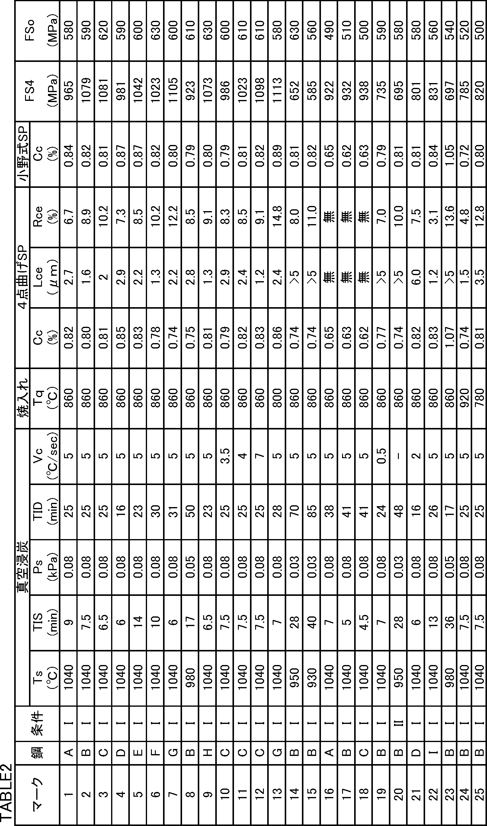
表2中の条件Iでは、次の条件で真空浸炭処理、焼入れ及び焼戻しを実施した。均熱工程S2では、表2に示す浸炭温度Ts(℃)で、試験片を60分均熱した。均熱工程S2を実施後、浸炭工程S3を実施した。浸炭工程時間TIS(min)及び浸炭工程時の浸炭ガス圧Ps(kPa)は表2に示すとおりであった。浸炭工程S3後、拡散工程S4を実施した。拡散工程時間TID(min)は表2に示すとおりであった。浸炭工程S3及び拡散工程S4は、それぞれ1回実施した。拡散工程後、表2に示す冷却速度Vcで、500℃までガス冷却を実施した。冷却ガスには窒素ガスを利用した。500℃以下となった後もガス冷却を続け、合計のガス冷却時間が20分となるまで冷却を継続した。ガス冷却時間が20分を経過した後、冷却を停止した。
冷却後、各試験片に対して次の条件で焼入れ及び焼戻し処理を実施した。鋼材を再び焼入れ温度Tq(表2参照)まで加熱した。この時の炉内雰囲気は窒素ガスであった。その後、焼入れ温度Tq(℃)で30分均熱した。均熱後、鋼材を油焼入れした。焼入れ後、鋼材に対して焼戻しを実施した。焼戻し温度は170℃であり、焼戻し温度での保持時間は2時間であった。
表2中の条件IIでは、次の条件で真空浸炭処理、焼入れ及び焼戻し処理を実施した。均熱工程S2では、950℃の浸炭温度Tsで60分均熱した。均熱工程S2を実施後、浸炭工程S3を実施した。浸炭工程時間TIS(min)及び浸炭ガス圧Pv(kPa)は表2に示すとおりであった。浸炭工程S3後、拡散工程S4を実施した。拡散工程時間TID(min)は表2に示すとおりであった。浸炭工程S3及び拡散工程S4は、それぞれ1回実施した。拡散工程後、鋼材を860℃まで炉冷(徐冷)した。したがって、条件IIではガス冷却を実施しなかった。
鋼材温度を860℃まで炉冷した後、鋼材を860℃で30分均熱し、油焼入れを実施した。焼入れ後、鋼材に対して焼戻しを実施した。焼戻し温度は170℃であり、焼戻し温度での保持時間は2時間であった。
以上の工程により真空浸炭処理された試験片(各試験番号ごとに複数の4点曲げ疲労試験片及び複数の小野式回転曲げ疲労試験片)を製造した。
[平坦表層部の炭素濃度測定試験]
真空浸炭処理、焼入れ及び焼戻し処理がされた複数の試験片のうち、各試験番号ごとに1つの4点曲げ疲労試験片及び1つの小野式回転曲げ疲労試験片を用いて、各試験片の平坦表層部の炭素濃度を測定した。具体的には、4点曲げ疲労試験片では、図1に示す点Pfを含む平坦部において、EPMA(電子線マイクロアナライザ)により平坦表層部の炭素濃度Cc(%)を測定した。
真空浸炭処理、焼入れ及び焼戻し処理がされた複数の試験片のうち、各試験番号ごとに1つの4点曲げ疲労試験片及び1つの小野式回転曲げ疲労試験片を用いて、各試験片の平坦表層部の炭素濃度を測定した。具体的には、4点曲げ疲労試験片では、図1に示す点Pfを含む平坦部において、EPMA(電子線マイクロアナライザ)により平坦表層部の炭素濃度Cc(%)を測定した。
同様に、小野式回転曲げ疲労試験片の環状半円溝の溝底の任意の点を含む部分領域において、EPMA(電子線マイクロアナライザ)により平坦表層部の炭素濃度Cc(%)を測定した。表2中の「4点曲げSP」欄の「Cc(%)」欄に4点曲げ疲労試験片の平坦表層部の炭素濃度(%)を示し、「小野式SP」欄の「Cc(%)」欄に小野式回転曲げ疲労試験片の平坦表層部の炭素濃度(%)を示す。
[エッジ表層部の組織観察試験]
製造された4点曲げ疲労試験片の浸炭部品を用いて、上述の方法により、エッジ表層部のセメンタイトの長さLce(μm)及びセメンタイト分率Rce(%)を求めた。なお、粗大なセメンタイトが析出している場合、1000倍の光学顕微鏡で上記視野を観察し、セメンタイト分率を求めた。
製造された4点曲げ疲労試験片の浸炭部品を用いて、上述の方法により、エッジ表層部のセメンタイトの長さLce(μm)及びセメンタイト分率Rce(%)を求めた。なお、粗大なセメンタイトが析出している場合、1000倍の光学顕微鏡で上記視野を観察し、セメンタイト分率を求めた。
[4点曲げ疲労試験]
各試験番号の複数の4点曲げ疲労試験片のうち、上記平坦表層部の炭素濃度測定試験及びエッジ表層部の組織観察試験に用いられなかった他の4点曲げ疲労試験片の浸炭部品を用いて、4点曲げ疲労試験を実施した。試験には、サーボ型疲労試験機を用いた。4点曲げ疲労試験片の支点間距離は45mmであった。最大負荷応力は1373MPaであり、最大負荷応力と最小負荷応力との応力比は0.1であった。周波数は10Hzであった。応力負荷繰り返し回数が1×10⁴回での破断強度を、4点曲げ疲労強度FS4(MPa)と評価した。
各試験番号の複数の4点曲げ疲労試験片のうち、上記平坦表層部の炭素濃度測定試験及びエッジ表層部の組織観察試験に用いられなかった他の4点曲げ疲労試験片の浸炭部品を用いて、4点曲げ疲労試験を実施した。試験には、サーボ型疲労試験機を用いた。4点曲げ疲労試験片の支点間距離は45mmであった。最大負荷応力は1373MPaであり、最大負荷応力と最小負荷応力との応力比は0.1であった。周波数は10Hzであった。応力負荷繰り返し回数が1×10⁴回での破断強度を、4点曲げ疲労強度FS4(MPa)と評価した。
[小野式回転曲げ疲労試験]
各試験番号の複数の小野式回転曲げ疲労試験片のうち、上記平坦表層部の炭素濃度測定試験に用いられなかった他の小野式回転曲げ疲労試験片に対して、JIS Z2274(1974)に準拠して、小野式回転曲げ疲労試験を室温(25℃)、大気中で、回転数3400rpmの条件で実施した。そして、応力付加繰返し回数が1×10⁷回において破断しない最大の応力(MPa)を、小野式回転曲げ疲労強度FSo(MPa)と定義した。
各試験番号の複数の小野式回転曲げ疲労試験片のうち、上記平坦表層部の炭素濃度測定試験に用いられなかった他の小野式回転曲げ疲労試験片に対して、JIS Z2274(1974)に準拠して、小野式回転曲げ疲労試験を室温(25℃)、大気中で、回転数3400rpmの条件で実施した。そして、応力付加繰返し回数が1×10⁷回において破断しない最大の応力(MPa)を、小野式回転曲げ疲労強度FSo(MPa)と定義した。
[試験結果]
表2に試験結果を示す。
表2に試験結果を示す。
試験番号1~13の浸炭部品の化学組成は適切であり、浸炭温度Ts(℃)、浸炭ガス圧Ps(kPa)、冷却速度Vc(℃/秒)及び焼入れ温度Tq(℃)も適切であり、各試験片の平坦部の炭素濃度も0.7%以上1.0%未満の範囲内であった。そのため、試験番号1~13の浸炭部品(4点曲げ疲労試験片)のエッジ表層部のセメンタイトの長さLceは3.0μm以内であり、セメンタイト分率Rceは5%以上であった。そのため、エッジ部の曲げ疲労強度の指標である4点曲げ疲労強度FS4は、850MPa以上と高かった。さらに、平坦部の曲げ疲労強度の指標である小野式回転曲げ疲労強度FSoも、520MPa以上と高かった。
一方、試験番号14、15及び20では、浸炭温度Tsが低すぎ、エッジ表層部のセメンタイトの長さLceが5μmを超えた。そのため、試験番号14、15及び20の4点曲げ疲労強度FS4は低かった。
試験番号16~18では、浸炭工程時間TIS及び/又は拡散工程時間TIDが不適切であった。具体的には、試験番号16の浸炭時間は、試験番号1よりも短かった。同様に、試験番号17の浸炭工程時間TISは、試験番号2よりも短く、試験番号18の浸炭工程時間TISは、試験番号3よりも短かった。そのため、試験番号16~18の平坦表層部の炭素濃度は0.7%未満であった。その結果、小野式回転曲げ疲労試験で得られた曲げ疲労強度は520MPa未満であり、平坦部の曲げ疲労強度FSoが低かった。さらに、試験番号16~18では、平坦表層部の炭素濃度が低すぎたため、エッジ表層部で過剰浸炭が発生しなかった。そのため、エッジ表層部にセメンタイトが析出しなかった。
試験番号19では、真空浸炭処理でのガス冷却速度Vcが3.5℃/秒未満であった。そのため、エッジ表層部に粗大なセメンタイトが析出し、セメンタイトの長さLceが5μmを超えた。そのため、4点曲げ疲労強度FS4が低かった。
試験番号21では、冷却速度Vcが低すぎた。そのため、セメンタイトの長さLceが5μmを超えた。そのため、4点曲げ疲労強度FS4が低かった。
試験番号22では、各製造条件は適切であったものの、Si含有量が高すぎた。そのため、エッジ部のセメンタイト分率Rceが低すぎた。そのため、4点曲げ疲労強度FS4が低かった。
試験番号23では、浸炭工程時間TIS及び/又は拡散工程時間TIDが不適切であったため、平坦表層部の炭素濃度が1.0%以上であった。そのため、エッジ部に粗大なセメンタイトが生成され、セメンタイトの長さLceが3.0μmを超えた。そのため、4点曲げ疲労強度FS4が低かった。
試験番号24では、焼入れ温度Tqが高すぎた。そのため、エッジ部の多くのセメンタイトが溶解してしまい、セメンタイト分率Rceが低かった。そのため、4点曲げ疲労強度FS4が低かった。
試験番号25では、焼入れ温度Tqが低すぎた。そのため、エッジ部のセメンタイトが溶解せず、分断されなかった。そのため、セメンタイトの長さLceが3.0μmを超え、4点曲げ疲労強度FS4が低かった。
以上、本発明の実施の形態を説明したが、上述した実施の形態は本発明を実施するための例示に過ぎない。よって、本発明は上述した実施の形態に限定されることなく、その趣旨を逸脱しない範囲内で上述した実施の形態を適宜変形して実施することが可能である。
Ac エッジ部
Af 平坦部
Vc 仮想円
Af 平坦部
Vc 仮想円
Claims (3)
- 鋼材に対して真空浸炭処理を実施して製造される浸炭部品であって、
前記浸炭部品の表面は、
3以上の面により形成される頂点と、前記頂点から1mm以内の表面部分とを含む頂点部と、
前記頂点から1mmよりも離れ、かつ、前記表面の辺から1mm以内の表面部分のうち、前記辺と垂直な断面において前記辺を中心とした半径1mmの仮想円と重複する部分の面積OA(mm2)と、前記重複する部分における前記浸炭部品の表面長さSL(mm)とが式(1)を満たす表面部分であるエッジ部と、
前記頂点部及び前記エッジ部以外の表面部分である平坦部とを含み、
前記鋼材は、質量%で、
C:0.10~0.30%、
Si:0.05~0.8%、
Mn:0.3~2.0%、
P:0.06%以下、
S:0.006~0.1%、
Cr:0.5~3.0%、
Al:0.01~0.1%、
N:0.025%以下、
Cu:0~0.5%、
Ni:0~0.5%、及び、
Mo:0~1.0%を含有し、残部はFe及び不純物からなり、
前記平坦部から0.05mmの深さまでの平坦表層部における炭素濃度は、質量%で、0.7%以上1.0%未満であり、
前記エッジ部から80μmの深さまでのエッジ表層部内のセメンタイトの長さは3.0μm以下であり、
前記エッジ表層部のセメンタイト分率は5~15%である、浸炭部品。
OA/SL≦0.7 (1) - 請求項1に記載の浸炭部品であって、
前記鋼材は、
Cu:0.1~0.5%、及び、
Ni:0.1~0.5%以下からなる群から選択される1種以上を含有する、浸炭部品。 - 請求項1又は請求項2に記載の浸炭部品であって、
前記鋼材は、
Mo:0.03~1.0%以下を含有する、浸炭部品。
Priority Applications (2)
| Application Number | Priority Date | Filing Date | Title |
|---|---|---|---|
| JP2014532815A JP5660259B2 (ja) | 2012-09-03 | 2013-09-02 | 浸炭部品 |
| CN201380043361.8A CN104583438B (zh) | 2012-09-03 | 2013-09-02 | 渗碳部件 |
Applications Claiming Priority (2)
| Application Number | Priority Date | Filing Date | Title |
|---|---|---|---|
| JP2012-192752 | 2012-09-03 | ||
| JP2012192752 | 2012-09-03 |
Publications (1)
| Publication Number | Publication Date |
|---|---|
| WO2014034150A1 true WO2014034150A1 (ja) | 2014-03-06 |
Family
ID=50182980
Family Applications (1)
| Application Number | Title | Priority Date | Filing Date |
|---|---|---|---|
| PCT/JP2013/005181 Ceased WO2014034150A1 (ja) | 2012-09-03 | 2013-09-02 | 浸炭部品 |
Country Status (3)
| Country | Link |
|---|---|
| JP (1) | JP5660259B2 (ja) |
| CN (1) | CN104583438B (ja) |
| WO (1) | WO2014034150A1 (ja) |
Cited By (5)
| Publication number | Priority date | Publication date | Assignee | Title |
|---|---|---|---|---|
| JP2016098432A (ja) * | 2014-11-26 | 2016-05-30 | 愛知製鋼株式会社 | 耐摩耗性に優れた浸炭部材及びその製造方法 |
| JP2016194156A (ja) * | 2015-03-31 | 2016-11-17 | 新日鐵住金株式会社 | 浸炭窒化部品および浸炭窒化部品の製造方法 |
| JP2017066498A (ja) * | 2015-10-02 | 2017-04-06 | 大同特殊鋼株式会社 | 鋼の熱処理方法および鋼部材 |
| CN113493883A (zh) * | 2020-03-18 | 2021-10-12 | 卡特彼勒公司 | 渗碳钢部件及渗碳工艺 |
| US20220049341A1 (en) * | 2018-09-12 | 2022-02-17 | Daido Steel Co., Ltd. | High surface-pressure resistant component and production method therefor |
Families Citing this family (2)
| Publication number | Priority date | Publication date | Assignee | Title |
|---|---|---|---|---|
| CN107604253A (zh) * | 2017-08-30 | 2018-01-19 | 东风商用车有限公司 | 一种高淬透性Mn‑Cr系列渗碳钢 |
| EP3950993A4 (en) * | 2019-03-29 | 2022-10-26 | Nippon Steel Corporation | CARBONED COMPONENT AND PROCESS FOR ITS MANUFACTURE |
Citations (5)
| Publication number | Priority date | Publication date | Assignee | Title |
|---|---|---|---|---|
| JPH083720A (ja) * | 1994-06-16 | 1996-01-09 | Sumitomo Metal Ind Ltd | 転動疲労寿命に優れた鋼製部品とその製造方法 |
| JP2004076125A (ja) * | 2002-08-21 | 2004-03-11 | Komatsu Ltd | 転動部材 |
| JP2007291486A (ja) * | 2005-08-24 | 2007-11-08 | Daido Steel Co Ltd | 浸炭部品 |
| JP2007308772A (ja) * | 2006-05-19 | 2007-11-29 | Kobe Steel Ltd | 浸炭部品およびその製造方法 |
| WO2011132722A1 (ja) * | 2010-04-19 | 2011-10-27 | 新日本製鐵株式会社 | 焼戻し軟化抵抗性に優れた鋼部品 |
Family Cites Families (3)
| Publication number | Priority date | Publication date | Assignee | Title |
|---|---|---|---|---|
| US8580050B2 (en) * | 2005-08-24 | 2013-11-12 | Daido Steel Co., Ltd. | Carburized machine parts |
| JP4971751B2 (ja) * | 2006-11-06 | 2012-07-11 | 本田技研工業株式会社 | 高濃度浸炭鋼の製造方法 |
| WO2010137607A1 (ja) * | 2009-05-27 | 2010-12-02 | 住友金属工業株式会社 | 浸炭部品およびその製造方法 |
-
2013
- 2013-09-02 CN CN201380043361.8A patent/CN104583438B/zh active Active
- 2013-09-02 JP JP2014532815A patent/JP5660259B2/ja active Active
- 2013-09-02 WO PCT/JP2013/005181 patent/WO2014034150A1/ja not_active Ceased
Patent Citations (5)
| Publication number | Priority date | Publication date | Assignee | Title |
|---|---|---|---|---|
| JPH083720A (ja) * | 1994-06-16 | 1996-01-09 | Sumitomo Metal Ind Ltd | 転動疲労寿命に優れた鋼製部品とその製造方法 |
| JP2004076125A (ja) * | 2002-08-21 | 2004-03-11 | Komatsu Ltd | 転動部材 |
| JP2007291486A (ja) * | 2005-08-24 | 2007-11-08 | Daido Steel Co Ltd | 浸炭部品 |
| JP2007308772A (ja) * | 2006-05-19 | 2007-11-29 | Kobe Steel Ltd | 浸炭部品およびその製造方法 |
| WO2011132722A1 (ja) * | 2010-04-19 | 2011-10-27 | 新日本製鐵株式会社 | 焼戻し軟化抵抗性に優れた鋼部品 |
Cited By (7)
| Publication number | Priority date | Publication date | Assignee | Title |
|---|---|---|---|---|
| JP2016098432A (ja) * | 2014-11-26 | 2016-05-30 | 愛知製鋼株式会社 | 耐摩耗性に優れた浸炭部材及びその製造方法 |
| JP2016194156A (ja) * | 2015-03-31 | 2016-11-17 | 新日鐵住金株式会社 | 浸炭窒化部品および浸炭窒化部品の製造方法 |
| JP2017066498A (ja) * | 2015-10-02 | 2017-04-06 | 大同特殊鋼株式会社 | 鋼の熱処理方法および鋼部材 |
| US20220049341A1 (en) * | 2018-09-12 | 2022-02-17 | Daido Steel Co., Ltd. | High surface-pressure resistant component and production method therefor |
| US12129557B2 (en) * | 2018-09-12 | 2024-10-29 | Daido Steel Co., Ltd. | High surface-pressure resistant component and production method therefor |
| CN113493883A (zh) * | 2020-03-18 | 2021-10-12 | 卡特彼勒公司 | 渗碳钢部件及渗碳工艺 |
| US12098466B2 (en) | 2020-03-18 | 2024-09-24 | Caterpillar Inc. | Carburized steel component and carburization process |
Also Published As
| Publication number | Publication date |
|---|---|
| JPWO2014034150A1 (ja) | 2016-08-08 |
| CN104583438B (zh) | 2016-10-12 |
| CN104583438A (zh) | 2015-04-29 |
| JP5660259B2 (ja) | 2015-01-28 |
Similar Documents
| Publication | Publication Date | Title |
|---|---|---|
| JP5660259B2 (ja) | 浸炭部品 | |
| JP5742801B2 (ja) | 熱間圧延棒鋼または線材 | |
| JP5824063B2 (ja) | 鋼製部品の製造方法 | |
| WO2015098106A1 (ja) | 浸炭鋼部品の製造方法及び浸炭鋼部品 | |
| JP6109729B2 (ja) | 浸炭処理時の結晶粒粗大化防止特性に優れた肌焼鋼 | |
| JP6589708B2 (ja) | 浸炭窒化部品 | |
| JP2011153364A (ja) | クランクシャフトおよびその製造方法 | |
| WO2019244503A1 (ja) | 機械部品 | |
| JP5886119B2 (ja) | 肌焼鋼鋼材 | |
| JPWO2013031587A1 (ja) | 熱間鍛造用圧延棒鋼又は線材 | |
| JP6414385B2 (ja) | 浸炭部品 | |
| JP6720643B2 (ja) | 浸炭部品 | |
| JP2018028130A (ja) | 浸炭部品 | |
| JP2016188421A (ja) | 浸炭部品 | |
| JP6447064B2 (ja) | 鋼部品 | |
| WO2018117015A1 (ja) | 軟窒化用非調質鋼、軟窒化部品、及び、軟窒化部品の製造方法 | |
| JP6838508B2 (ja) | 真空浸炭用鋼及び浸炭部品 | |
| JP2016188422A (ja) | 浸炭部品 | |
| JP7417171B2 (ja) | 鋼材 | |
| JP6465206B2 (ja) | 熱間圧延棒線材、部品および熱間圧延棒線材の製造方法 | |
| JP4411096B2 (ja) | 球状化後の冷間鍛造性に優れた肌焼用鋼線材・棒鋼 | |
| JP7323850B2 (ja) | 鋼材及び浸炭鋼部品 | |
| JP2013112826A (ja) | 耐摩耗性と面疲労特性に優れた高周波焼入歯車およびその製造方法 | |
| JP7587124B2 (ja) | 浸炭用鋼、浸炭鋼部品および浸炭鋼部品の製造方法 | |
| JP2024007540A (ja) | 鋼材、及び、真空浸炭機械構造用部品 |
Legal Events
| Date | Code | Title | Description |
|---|---|---|---|
| 121 | Ep: the epo has been informed by wipo that ep was designated in this application |
Ref document number: 13833426 Country of ref document: EP Kind code of ref document: A1 |
|
| ENP | Entry into the national phase |
Ref document number: 2014532815 Country of ref document: JP Kind code of ref document: A |
|
| NENP | Non-entry into the national phase |
Ref country code: DE |
|
| 122 | Ep: pct application non-entry in european phase |
Ref document number: 13833426 Country of ref document: EP Kind code of ref document: A1 |