WO2014034087A1 - 火花点火式直噴エンジン - Google Patents
火花点火式直噴エンジン Download PDFInfo
- Publication number
- WO2014034087A1 WO2014034087A1 PCT/JP2013/005033 JP2013005033W WO2014034087A1 WO 2014034087 A1 WO2014034087 A1 WO 2014034087A1 JP 2013005033 W JP2013005033 W JP 2013005033W WO 2014034087 A1 WO2014034087 A1 WO 2014034087A1
- Authority
- WO
- WIPO (PCT)
- Prior art keywords
- fuel
- cylinder
- region
- engine
- valve
- Prior art date
- Legal status (The legal status is an assumption and is not a legal conclusion. Google has not performed a legal analysis and makes no representation as to the accuracy of the status listed.)
- Ceased
Links
Images














Classifications
-
- F—MECHANICAL ENGINEERING; LIGHTING; HEATING; WEAPONS; BLASTING
- F02—COMBUSTION ENGINES; HOT-GAS OR COMBUSTION-PRODUCT ENGINE PLANTS
- F02B—INTERNAL-COMBUSTION PISTON ENGINES; COMBUSTION ENGINES IN GENERAL
- F02B11/00—Engines characterised by both fuel-air mixture compression and air compression, or characterised by both positive ignition and compression ignition, e.g. in different cylinders
- F02B11/02—Engines characterised by both fuel-air mixture compression and air compression, or characterised by both positive ignition and compression ignition, e.g. in different cylinders convertible from fuel-air mixture compression to air compression or vice versa
-
- F—MECHANICAL ENGINEERING; LIGHTING; HEATING; WEAPONS; BLASTING
- F02—COMBUSTION ENGINES; HOT-GAS OR COMBUSTION-PRODUCT ENGINE PLANTS
- F02B—INTERNAL-COMBUSTION PISTON ENGINES; COMBUSTION ENGINES IN GENERAL
- F02B23/00—Other engines characterised by special shape or construction of combustion chambers to improve operation
- F02B23/08—Other engines characterised by special shape or construction of combustion chambers to improve operation with positive ignition
- F02B23/10—Other engines characterised by special shape or construction of combustion chambers to improve operation with positive ignition with separate admission of air and fuel into cylinder
- F02B23/101—Other engines characterised by special shape or construction of combustion chambers to improve operation with positive ignition with separate admission of air and fuel into cylinder the injector being placed on or close to the cylinder centre axis, e.g. with mixture formation using spray guided concepts
-
- F—MECHANICAL ENGINEERING; LIGHTING; HEATING; WEAPONS; BLASTING
- F02—COMBUSTION ENGINES; HOT-GAS OR COMBUSTION-PRODUCT ENGINE PLANTS
- F02B—INTERNAL-COMBUSTION PISTON ENGINES; COMBUSTION ENGINES IN GENERAL
- F02B29/00—Engines characterised by provision for charging or scavenging not provided for in groups F02B25/00, F02B27/00 or F02B33/00 - F02B39/00; Details thereof
- F02B29/04—Cooling of air intake supply
- F02B29/0406—Layout of the intake air cooling or coolant circuit
- F02B29/0418—Layout of the intake air cooling or coolant circuit the intake air cooler having a bypass or multiple flow paths within the heat exchanger to vary the effective heat transfer surface
-
- F—MECHANICAL ENGINEERING; LIGHTING; HEATING; WEAPONS; BLASTING
- F02—COMBUSTION ENGINES; HOT-GAS OR COMBUSTION-PRODUCT ENGINE PLANTS
- F02D—CONTROLLING COMBUSTION ENGINES
- F02D13/00—Controlling the engine output power by varying inlet or exhaust valve operating characteristics, e.g. timing
- F02D13/02—Controlling the engine output power by varying inlet or exhaust valve operating characteristics, e.g. timing during engine operation
- F02D13/0203—Variable control of intake and exhaust valves
- F02D13/0207—Variable control of intake and exhaust valves changing valve lift or valve lift and timing
-
- F—MECHANICAL ENGINEERING; LIGHTING; HEATING; WEAPONS; BLASTING
- F02—COMBUSTION ENGINES; HOT-GAS OR COMBUSTION-PRODUCT ENGINE PLANTS
- F02D—CONTROLLING COMBUSTION ENGINES
- F02D13/00—Controlling the engine output power by varying inlet or exhaust valve operating characteristics, e.g. timing
- F02D13/02—Controlling the engine output power by varying inlet or exhaust valve operating characteristics, e.g. timing during engine operation
- F02D13/0261—Controlling the valve overlap
-
- F—MECHANICAL ENGINEERING; LIGHTING; HEATING; WEAPONS; BLASTING
- F02—COMBUSTION ENGINES; HOT-GAS OR COMBUSTION-PRODUCT ENGINE PLANTS
- F02D—CONTROLLING COMBUSTION ENGINES
- F02D21/00—Controlling engines characterised by their being supplied with non-airborne oxygen or other non-fuel gas
- F02D21/06—Controlling engines characterised by their being supplied with non-airborne oxygen or other non-fuel gas peculiar to engines having other non-fuel gas added to combustion air
- F02D21/08—Controlling engines characterised by their being supplied with non-airborne oxygen or other non-fuel gas peculiar to engines having other non-fuel gas added to combustion air the other gas being the exhaust gas of engine
-
- F—MECHANICAL ENGINEERING; LIGHTING; HEATING; WEAPONS; BLASTING
- F02—COMBUSTION ENGINES; HOT-GAS OR COMBUSTION-PRODUCT ENGINE PLANTS
- F02D—CONTROLLING COMBUSTION ENGINES
- F02D37/00—Non-electrical conjoint control of two or more functions of engines, not otherwise provided for
- F02D37/02—Non-electrical conjoint control of two or more functions of engines, not otherwise provided for one of the functions being ignition
-
- F—MECHANICAL ENGINEERING; LIGHTING; HEATING; WEAPONS; BLASTING
- F02—COMBUSTION ENGINES; HOT-GAS OR COMBUSTION-PRODUCT ENGINE PLANTS
- F02D—CONTROLLING COMBUSTION ENGINES
- F02D41/00—Electrical control of supply of combustible mixture or its constituents
- F02D41/0025—Controlling engines characterised by use of non-liquid fuels, pluralities of fuels, or non-fuel substances added to the combustible mixtures
- F02D41/0047—Controlling exhaust gas recirculation [EGR]
- F02D41/005—Controlling exhaust gas recirculation [EGR] according to engine operating conditions
- F02D41/0057—Specific combustion modes
-
- F—MECHANICAL ENGINEERING; LIGHTING; HEATING; WEAPONS; BLASTING
- F02—COMBUSTION ENGINES; HOT-GAS OR COMBUSTION-PRODUCT ENGINE PLANTS
- F02D—CONTROLLING COMBUSTION ENGINES
- F02D41/00—Electrical control of supply of combustible mixture or its constituents
- F02D41/30—Controlling fuel injection
- F02D41/3011—Controlling fuel injection according to or using specific or several modes of combustion
- F02D41/3017—Controlling fuel injection according to or using specific or several modes of combustion characterised by the mode(s) being used
-
- F—MECHANICAL ENGINEERING; LIGHTING; HEATING; WEAPONS; BLASTING
- F02—COMBUSTION ENGINES; HOT-GAS OR COMBUSTION-PRODUCT ENGINE PLANTS
- F02D—CONTROLLING COMBUSTION ENGINES
- F02D41/00—Electrical control of supply of combustible mixture or its constituents
- F02D41/30—Controlling fuel injection
- F02D41/3011—Controlling fuel injection according to or using specific or several modes of combustion
- F02D41/3017—Controlling fuel injection according to or using specific or several modes of combustion characterised by the mode(s) being used
- F02D41/3023—Controlling fuel injection according to or using specific or several modes of combustion characterised by the mode(s) being used a mode being the stratified charge spark-ignited mode
-
- F—MECHANICAL ENGINEERING; LIGHTING; HEATING; WEAPONS; BLASTING
- F02—COMBUSTION ENGINES; HOT-GAS OR COMBUSTION-PRODUCT ENGINE PLANTS
- F02D—CONTROLLING COMBUSTION ENGINES
- F02D41/00—Electrical control of supply of combustible mixture or its constituents
- F02D41/30—Controlling fuel injection
- F02D41/3011—Controlling fuel injection according to or using specific or several modes of combustion
- F02D41/3017—Controlling fuel injection according to or using specific or several modes of combustion characterised by the mode(s) being used
- F02D41/3035—Controlling fuel injection according to or using specific or several modes of combustion characterised by the mode(s) being used a mode being the premixed charge compression-ignition mode
-
- F—MECHANICAL ENGINEERING; LIGHTING; HEATING; WEAPONS; BLASTING
- F02—COMBUSTION ENGINES; HOT-GAS OR COMBUSTION-PRODUCT ENGINE PLANTS
- F02D—CONTROLLING COMBUSTION ENGINES
- F02D41/00—Electrical control of supply of combustible mixture or its constituents
- F02D41/30—Controlling fuel injection
- F02D41/38—Controlling fuel injection of the high pressure type
- F02D41/40—Controlling fuel injection of the high pressure type with means for controlling injection timing or duration
- F02D41/401—Controlling injection timing
-
- F—MECHANICAL ENGINEERING; LIGHTING; HEATING; WEAPONS; BLASTING
- F02—COMBUSTION ENGINES; HOT-GAS OR COMBUSTION-PRODUCT ENGINE PLANTS
- F02M—SUPPLYING COMBUSTION ENGINES IN GENERAL WITH COMBUSTIBLE MIXTURES OR CONSTITUENTS THEREOF
- F02M26/00—Engine-pertinent apparatus for adding exhaust gases to combustion-air, main fuel or fuel-air mixture, e.g. by exhaust gas recirculation [EGR] systems
- F02M26/13—Arrangement or layout of EGR passages, e.g. in relation to specific engine parts or for incorporation of accessories
- F02M26/22—Arrangement or layout of EGR passages, e.g. in relation to specific engine parts or for incorporation of accessories with coolers in the recirculation passage
- F02M26/23—Layout, e.g. schematics
- F02M26/25—Layout, e.g. schematics with coolers having bypasses
-
- F—MECHANICAL ENGINEERING; LIGHTING; HEATING; WEAPONS; BLASTING
- F02—COMBUSTION ENGINES; HOT-GAS OR COMBUSTION-PRODUCT ENGINE PLANTS
- F02M—SUPPLYING COMBUSTION ENGINES IN GENERAL WITH COMBUSTIBLE MIXTURES OR CONSTITUENTS THEREOF
- F02M26/00—Engine-pertinent apparatus for adding exhaust gases to combustion-air, main fuel or fuel-air mixture, e.g. by exhaust gas recirculation [EGR] systems
- F02M26/13—Arrangement or layout of EGR passages, e.g. in relation to specific engine parts or for incorporation of accessories
- F02M26/22—Arrangement or layout of EGR passages, e.g. in relation to specific engine parts or for incorporation of accessories with coolers in the recirculation passage
- F02M26/33—Arrangement or layout of EGR passages, e.g. in relation to specific engine parts or for incorporation of accessories with coolers in the recirculation passage controlling the temperature of the recirculated gases
-
- F—MECHANICAL ENGINEERING; LIGHTING; HEATING; WEAPONS; BLASTING
- F02—COMBUSTION ENGINES; HOT-GAS OR COMBUSTION-PRODUCT ENGINE PLANTS
- F02P—IGNITION, OTHER THAN COMPRESSION IGNITION, FOR INTERNAL-COMBUSTION ENGINES; TESTING OF IGNITION TIMING IN COMPRESSION-IGNITION ENGINES
- F02P15/00—Electric spark ignition having characteristics not provided for in, or of interest apart from, groups F02P1/00 - F02P13/00 and combined with layout of ignition circuits
- F02P15/08—Electric spark ignition having characteristics not provided for in, or of interest apart from, groups F02P1/00 - F02P13/00 and combined with layout of ignition circuits having multiple-spark ignition, i.e. ignition occurring simultaneously at different places in one engine cylinder or in two or more separate engine cylinders
-
- F—MECHANICAL ENGINEERING; LIGHTING; HEATING; WEAPONS; BLASTING
- F02—COMBUSTION ENGINES; HOT-GAS OR COMBUSTION-PRODUCT ENGINE PLANTS
- F02P—IGNITION, OTHER THAN COMPRESSION IGNITION, FOR INTERNAL-COMBUSTION ENGINES; TESTING OF IGNITION TIMING IN COMPRESSION-IGNITION ENGINES
- F02P5/00—Advancing or retarding ignition; Control therefor
- F02P5/04—Advancing or retarding ignition; Control therefor automatically, as a function of the working conditions of the engine or vehicle or of the atmospheric conditions
- F02P5/145—Advancing or retarding ignition; Control therefor automatically, as a function of the working conditions of the engine or vehicle or of the atmospheric conditions using electrical means
- F02P5/15—Digital data processing
- F02P5/1502—Digital data processing using one central computing unit
- F02P5/1516—Digital data processing using one central computing unit with means relating to exhaust gas recirculation, e.g. turbo
-
- F—MECHANICAL ENGINEERING; LIGHTING; HEATING; WEAPONS; BLASTING
- F02—COMBUSTION ENGINES; HOT-GAS OR COMBUSTION-PRODUCT ENGINE PLANTS
- F02D—CONTROLLING COMBUSTION ENGINES
- F02D41/00—Electrical control of supply of combustible mixture or its constituents
- F02D41/30—Controlling fuel injection
- F02D41/3011—Controlling fuel injection according to or using specific or several modes of combustion
- F02D41/3017—Controlling fuel injection according to or using specific or several modes of combustion characterised by the mode(s) being used
- F02D2041/3052—Controlling fuel injection according to or using specific or several modes of combustion characterised by the mode(s) being used the mode being the stratified charge compression-ignition mode
-
- F—MECHANICAL ENGINEERING; LIGHTING; HEATING; WEAPONS; BLASTING
- F02—COMBUSTION ENGINES; HOT-GAS OR COMBUSTION-PRODUCT ENGINE PLANTS
- F02D—CONTROLLING COMBUSTION ENGINES
- F02D41/00—Electrical control of supply of combustible mixture or its constituents
- F02D41/30—Controlling fuel injection
- F02D41/38—Controlling fuel injection of the high pressure type
- F02D41/40—Controlling fuel injection of the high pressure type with means for controlling injection timing or duration
- F02D41/402—Multiple injections
-
- Y—GENERAL TAGGING OF NEW TECHNOLOGICAL DEVELOPMENTS; GENERAL TAGGING OF CROSS-SECTIONAL TECHNOLOGIES SPANNING OVER SEVERAL SECTIONS OF THE IPC; TECHNICAL SUBJECTS COVERED BY FORMER USPC CROSS-REFERENCE ART COLLECTIONS [XRACs] AND DIGESTS
- Y02—TECHNOLOGIES OR APPLICATIONS FOR MITIGATION OR ADAPTATION AGAINST CLIMATE CHANGE
- Y02T—CLIMATE CHANGE MITIGATION TECHNOLOGIES RELATED TO TRANSPORTATION
- Y02T10/00—Road transport of goods or passengers
- Y02T10/10—Internal combustion engine [ICE] based vehicles
- Y02T10/12—Improving ICE efficiencies
-
- Y—GENERAL TAGGING OF NEW TECHNOLOGICAL DEVELOPMENTS; GENERAL TAGGING OF CROSS-SECTIONAL TECHNOLOGIES SPANNING OVER SEVERAL SECTIONS OF THE IPC; TECHNICAL SUBJECTS COVERED BY FORMER USPC CROSS-REFERENCE ART COLLECTIONS [XRACs] AND DIGESTS
- Y02—TECHNOLOGIES OR APPLICATIONS FOR MITIGATION OR ADAPTATION AGAINST CLIMATE CHANGE
- Y02T—CLIMATE CHANGE MITIGATION TECHNOLOGIES RELATED TO TRANSPORTATION
- Y02T10/00—Road transport of goods or passengers
- Y02T10/10—Internal combustion engine [ICE] based vehicles
- Y02T10/40—Engine management systems
Definitions
- the technology disclosed herein relates to a spark ignition direct injection engine.
- Patent Document 1 describes a spark-ignition direct injection engine having a high compression ratio in which a geometric compression ratio is set to 14 or more. In an engine with a high compression ratio, knocking is likely to occur when the operating region is in a low speed region and a high load region including a fully open load. Patent Document 1 also describes a technique for adjusting the closing timing of the intake valve so that the effective compression ratio is lowered in a low-speed, high-load region. By avoiding knocking, the ignition timing can be advanced as much as possible, and the engine torque is improved.
- Patent Document 2 a combustion mode in which a lean air-fuel mixture is compressed and ignited is known as a technique for achieving both improvement in exhaust emission and improvement in thermal efficiency.
- increasing the geometric compression ratio increases the compression end pressure and the compression end temperature, which is advantageous for stabilizing the compression ignition combustion.
- compression ignition combustion becomes pre-ignition combustion with a strong pressure rise (dP / dt). End up. Therefore, it is difficult to expand the region where compression ignition combustion is performed to the high load side due to the restriction of NVH (Noise Vibration Harshness). Therefore, as described in Patent Document 2, even in an engine that performs compression ignition combustion, spark ignition combustion is performed not by compression ignition combustion but by driving an ignition plug in an operation region on the high load side. Is common.
- Patent Document 3 in an engine that switches between compression ignition combustion and spark ignition combustion according to the operating state of the engine, EGR gas is introduced into the cylinder at the time of switching transition from compression ignition combustion to spark ignition combustion, and A technique for avoiding knocking by making the air-fuel ratio richer than the stoichiometric air-fuel ratio is described.
- an engine that performs compression ignition combustion can switch compression ignition combustion with excellent exhaust emission performance and thermal efficiency as much as possible, although the combustion mode can be switched to perform spark ignition combustion in the operating region on the high load side due to NVH restrictions. There is also a demand to execute up to the high load side.
- the technology disclosed herein has been made in view of such a point, and the object thereof is, for example, in a spark ignition direct injection engine in which the geometric compression ratio is set to be relatively high, such as 15 or more.
- An object of the present invention is to expand the region where compression ignition combustion is performed to the high load side and to avoid abnormal combustion in the region where spark ignition combustion is performed.
- Pre-ignition is an auto-ignition reaction that accompanies the compression of the unburned mixture during the compression stroke, and knocking is the unburned portion of the mixture due to expansion of the burned portion during combustion of the mixture. It is a self-ignition reaction that accompanies compression.
- the conventional engine that injects fuel during the intake stroke has a long unburned mixture reaction possible time, which is the time from the start of fuel injection to the end of combustion. This long unburned mixture reaction possible time is one of the factors causing abnormal combustion such as pre-ignition and / or knocking.
- the inventors of the present application may inject fuel into the cylinder with relatively high fuel pressure at a timing near the compression top dead center. It has been found that it is effective in shortening the gas reaction possible time and thereby avoiding abnormal combustion.
- the inventors of the present application also said that the injection mode in which the fuel is injected into the cylinder at a timing near the compression top dead center at a high fuel pressure is in a high load region in a region where compression ignition combustion is performed. It has been found that compression ignition combustion is stably performed during the expansion stroke period. The inventors of the present application have found that compression ignition combustion in the expansion stroke period is effective in avoiding a sudden pressure increase in the cylinder, and have completed the technique disclosed herein.
- the spark ignition direct injection engine disclosed herein is configured to have an engine body configured to have a cylinder having a geometric compression ratio set to 15 or more, and to inject fuel into the cylinder.
- a spark plug configured to perform exhaust gas
- an exhaust gas recirculation system configured to introduce exhaust gas into the cylinder, at least the fuel injection valve, the fuel pressure setting mechanism, the spark plug, and the exhaust gas recirculation system.
- a controller configured to operate the engine body by controlling.
- the controller operates the engine body by compression ignition combustion for compressing and igniting an air-fuel mixture in the cylinder when the operation state of the engine body is in a predetermined low load region, and the operation state of the engine body is When in a high load region where the load is higher than the low load region, the spark plug is operated at a predetermined timing so that the engine body is operated by spark ignition combustion.
- the controller also includes the fuel pressure setting mechanism when the operating state of the engine body is at least in a predetermined first specific region including a boundary between the low load region and the high load region in the low load region. And the fuel injection valve is driven so as to inject fuel into the cylinder at least within a period from the latter stage of the compression stroke to the early stage of the expansion stroke, and the engine body.
- the fuel pressure is set to a high fuel pressure of 30 MPa or more by the fuel pressure setting mechanism, and at least in the late stage of the compression stroke
- the fuel injection valve is driven so as to inject fuel into the cylinder within a period from the initial expansion stroke to the initial stage of the expansion stroke. Performs spark ignition to the mixture gas in the cylinder by driving the ignition plug after the end of fuel injection.
- the controller further determines an EGR rate, which is a ratio of the exhaust gas amount to the total gas amount in the cylinder, through the control of the exhaust gas recirculation system, within the first specific region of the low load region.
- the region is set to be higher than the EGR rate in the second specific region, and the fuel injection start timing in the first specific region is advanced from the fuel injection start timing in the second specific region. .
- the geometric compression ratio of the engine body may be set to 15 or more and, for example, 20 or less.
- the latter half of the compression stroke may be defined as the latter half when the compression stroke is divided into three periods, an initial period, a middle period, and a late period.
- the “expansion stroke initial stage” may be defined as an initial stage when the expansion stroke is divided into three periods of an initial period, a middle period, and a late period.
- the exhaust gas recirculation system includes an external EGR system configured to recirculate exhaust gas to the intake side through the EGR passage, and the exhaust gas confined in the cylinder or exhaust gas discharged to the intake or exhaust port to the cylinder.
- an internal EGR system configured to be re-inhaled.
- the engine body When the operating area of the engine body is in a relatively low load area, the engine body is operated by compression ignition combustion that compresses and ignites the air-fuel mixture in the cylinder. Since the engine body is set to a high compression ratio of 15 or more, the compression end pressure and the compression end temperature are increased. High compression end pressure and high compression end temperature stabilize compression ignition combustion.
- compression ignition combustion becomes a combustion with a strong pressure rise.
- fuel is injected into the cylinder at least with a high fuel pressure of 30 MPa or more and at least within the period from the late compression stroke to the early expansion stroke.
- the first specific region is a region on the high load side even in the low load region including the boundary between the low load region and the high load region in which spark ignition combustion is performed.
- the high fuel pressure shortens the period during which fuel is injected into the cylinder, that is, the injection period, as compared with the low fuel pressure. This is advantageous in shortening the time from the start of fuel injection to compression ignition.
- high fuel pressure is advantageous for atomization of fuel spray injected into the cylinder, and also increases the gas turbulence accompanying injection of fuel into the cylinder with high fuel pressure, and near the compression top dead center.
- Gas turbulence energy increases in a cylinder.
- pre-ignition within the compression stroke period is avoided by injecting the fuel into the cylinder at least from the latter stage of the compression stroke to the early stage of the expansion stroke.
- the homogeneous mixture is surely compressed and ignited after compression top dead center, and in the expansion stroke period. Combustion is performed stably.
- the expansion stroke since the cylinder pressure gradually decreases due to motoring, the pressure increase of the compression ignition combustion is suppressed and the combustion becomes relatively slow.
- the fuel injection in the first specific region may be performed in a divided manner.
- at least one of the plurality of fuel injections performed in a divided manner is performed from the late stage of the compression stroke to the initial stage of the expansion stroke. It can be done relatively late.
- exhaust gas that is, EGR gas
- EGR gas exhaust gas
- the compression ignition combustion in the expansion stroke becomes even slower, which is further advantageous in avoiding a sudden pressure increase.
- the NVH restriction in the first specific region is eliminated, and the region where compression ignition combustion is performed can be expanded to the high load side.
- the engine body when the operating region of the engine body is in a relatively high load region, the engine body is operated by spark ignition combustion in which the air-fuel mixture in the cylinder is combusted by spark ignition. And at least in the second specific region of the high load including the fully open load in the high load region, at least the period from the late stage of the compression stroke to the initial stage of the expansion stroke at a high fuel pressure of 30 MPa or more as in the first specific region.
- the fuel is injected into the cylinder.
- the high fuel pressure shortens the fuel injection period and increases the mixing performance of the atomized fuel spray to form a combustible mixture in a short time. It should be noted that this characteristic fuel injection may also be performed in a region other than the second specific region.
- the spark plug is driven at a predetermined timing after the end of fuel injection to ignite the air-fuel mixture in the cylinder.
- the ignition timing may be a predetermined timing after compression top dead center.
- the fuel injection into the cylinder at a relatively late timing near the compression top dead center at a high fuel pressure shortens the injection period. It is possible to shorten the mixture formation period and the combustion period. Due to the high geometric compression ratio of the engine body, in this engine, abnormal combustion such as pre-ignition and knocking is likely to occur in the second specific region on the high load side. However, the above-described configuration effectively avoids abnormal combustion such as pre-ignition and knocking by shortening the mixture reaction possible period, which is the sum of the injection period, the mixture formation period, and the combustion period. .
- the fuel injection start timing in the first specific region in the low load region is high load It is advanced from the fuel injection start time in the second specific region. This is mainly due to the difference between the EGR rate in the first specific region in the low load region and the EGR rate in the second specific region in the high load region. That is, the first specific region is a low-load region where the compression ignition combustion is performed and the load is relatively low, so that a large amount of EGR gas can be introduced into the cylinder.
- the start timing of fuel injection can be further advanced as long as abnormal combustion such as pre-ignition can be avoided.
- a long period of formation of the homogeneous mixture is ensured to a certain extent to improve the ignitability and combustion stability, and the compression ignition timing is delayed after the compression top dead center, thereby producing a large amount of EGR. It becomes possible to avoid a rapid pressure rise with slowing of combustion by gas.
- the second specific region is a high load region in which spark ignition combustion is performed and the load is relatively high. From the viewpoint of the stability of spark ignition combustion, since a large amount of EGR gas cannot be introduced into the cylinder, in the second specific region, it is desirable to avoid abnormal combustion by delaying the start timing of fuel injection as much as possible. .
- the technology disclosed herein also includes a cylinder in which the geometric compression ratio is set to 15 or more, and a piston that is reciprocally inserted in the cylinder and has a concave cavity formed in the crown surface thereof.
- An engine body configured as described above, a fuel injection valve configured to inject fuel into the cavity when the piston is positioned near the compression top dead center, and the fuel injected by the fuel injection valve
- a fuel pressure setting mechanism configured to set the pressure of the engine
- An exhaust gas recirculation system configured to be introduced into the engine body, and at least the fuel injection valve, the fuel pressure setting mechanism, the spark plug, and the exhaust gas recirculation system to control the engine body.
- a controller configured to rolling, according to the direct-injection spark-ignition engine with.
- the controller operates the engine main body by compression ignition combustion for compressing and igniting the air-fuel mixture in the cylinder when the operating state of the engine main body is in a predetermined low load region, and the operation of the engine main body.
- the spark plug is operated at a predetermined timing so as to operate the engine body by spark ignition combustion, and the controller also
- the fuel pressure is set to 30 MPa or more by the fuel pressure setting mechanism.
- the fuel injection valve at a timing at which the fuel is injected into the cavity of the piston.
- the fuel pressure is set to a high fuel pressure of 30 MPa or more by the fuel pressure setting mechanism, and The fuel injection valve is driven at the timing of injecting the fuel into the cavity of the piston, and the spark plug is driven after the fuel injection is finished to ignite the air-fuel mixture in the cylinder.
- the controller further determines an EGR rate, which is a ratio of the exhaust gas amount to the total gas amount in the cylinder, through the control of the exhaust gas recirculation system, within the first specific region of the low load region.
- the region is set to be higher than the EGR rate in the second specific region, and the fuel injection start timing in the first specific region is advanced from the fuel injection start timing in the second specific region. .
- the fuel injection valve is operated at a timing at which fuel is injected into the cavity formed in the crown surface of the piston with a high fuel pressure of 30 MPa or more.
- a high fuel pressure of 30 MPa or more.
- the high fuel pressure shortens the fuel injection period and promotes atomization of the fuel spray.
- by injecting fuel into the cavity at a high fuel pressure it is possible to strengthen the gas flow in the cavity and quickly form a relatively homogeneous air-fuel mixture.
- the timing at which fuel is injected into the cavity corresponds to the timing at which the piston is positioned near the compression top dead center, the relatively homogeneous air-fuel mixture is reliably compressed and ignited after the compression top dead center, and the expansion stroke Burns stably in
- exhaust gas is introduced into the cylinder, so that compression ignition combustion in the expansion stroke becomes further slow, which is further advantageous in avoiding a sudden pressure increase.
- the above configuration is advantageous in expanding the low load region in which compression ignition combustion is performed to the high load side.
- the geometric compression of the engine body is set to a high compression ratio of 15 or more, the volume of the combustion chamber when the piston is located near the compression top dead center is relatively small. Can be. Injecting high fuel pressure fuel into the cavity at this timing is advantageous in increasing the utilization rate of air in the cavity and promptly forming a homogeneous air-fuel mixture. That is, in the engine body having a high geometric compression ratio, the ignitability and stability of the compression ignition combustion are improved.
- the fuel is injected at a timing at which fuel is injected into the cavity formed in the crown surface of the piston with a high fuel pressure of at least 30 MPa.
- a high fuel pressure of at least 30 MPa.
- This shortens the fuel injection period promotes atomization of the fuel spray, further strengthens the gas flow in the cavity, and forms a combustible mixture in a short time.
- the combustion period is shortened because combustion is started by spark ignition while maintaining strong turbulent energy in the cavity. As a result, abnormal combustion such as pre-ignition and knocking can be effectively avoided while ensuring combustion stability.
- injecting fuel into the cavity at a high fuel pressure increases the utilization rate of air in the cavity and increases the geometric compression ratio engine. In the main body, it contributes to the stability of spark ignition combustion.
- a relatively large amount of EGR gas is introduced into the cylinder in the first specific region of the low load region.
- the fuel injection start timing is further advanced to form a more homogeneous air-fuel mixture, and both improvement in ignitability and combustion stability and avoidance of a rapid pressure increase are achieved.
- a relatively small amount of EGR gas is introduced into the cylinder, while abnormal combustion can be avoided by delaying the fuel injection start timing as much as possible.
- the exhaust gas recirculation system includes an external EGR system configured to recirculate the exhaust gas into the cylinder via an EGR passage that communicates an exhaust passage and an intake passage of the engine body, an intake valve of the engine body, An internal EGR system configured to recirculate the exhaust gas into the cylinder by opening / closing control of an exhaust valve, and the controller is configured to control the external EGR system in the first specific region of the low load region.
- the cooled exhaust gas may be introduced into the cylinder via the EGR passage.
- the first specific region is a region where the load is relatively high, the temperature in the cylinder is relatively high, and the pressure increase in the compression ignition combustion tends to be abrupt. Therefore, in the first specific region, the cooled exhaust gas is introduced into the cylinder via the EGR passage of the external EGR system. As a result, an increase in the temperature in the cylinder is suppressed, and abnormal combustion such as pre-ignition and sudden pressure increase due to compression ignition combustion are avoided.
- the exhaust gas recirculation system is configured such that a cooled EGR gas that has cooled the exhaust gas and a hot EGR gas that is higher in temperature than the cooled EGR gas can be introduced into the cylinder, and the controller has the low load
- a cooled EGR gas that has cooled the exhaust gas and a hot EGR gas that is higher in temperature than the cooled EGR gas can be introduced into the cylinder, and the controller has the low load
- the first specific region of the region at least the cooled EGR gas is introduced into the cylinder through the exhaust gas recirculation system, and a predetermined minimum load that is lower than the first specific region in the low load region.
- only the hot EGR gas may be introduced into the cylinder through the exhaust gas recirculation system.
- the controller has at least a period from the intake stroke to the middle of the compression stroke in a region excluding the first specific region in the low load region and a high speed region equal to or higher than a predetermined rotation speed in the high load region.
- the fuel injection valve may be driven to perform fuel injection.
- the region excluding the first specific region in the low load region is a region with a relatively low load in the low load region.
- the temperature in the cylinder is relatively low, so the pressure rises due to compression ignition combustion. In the first place, it is possible to avoid suddenly. Therefore, in this region, fuel injection is performed at least within the period from the intake stroke to the middle of the compression stroke. In this case, fuel is injected during a period in which the intake air flow is strong, and the mixture formation period is ensured sufficiently long, so that a homogeneous mixture is formed. Further, since the fuel is injected when the piston position is far from the top dead center, the air utilization rate in the cylinder is also increased. As a result, the ignitability of compression ignition is improved and the stability of compression ignition combustion is improved.
- fuel injection is performed at least within the period from the intake stroke to the middle of the compression stroke even in a high-speed region of a predetermined rotation speed or higher in a high load region where spark ignition combustion is performed.
- delaying the fuel injection timing is effective in avoiding abnormal combustion in the low speed region of the engine where the real time for the crank angle change is long.
- the actual time for changing the crank angle is short in the high speed region of the engine, there is little merit in shortening the unburned mixture reaction possible time by delaying the fuel injection timing.
- the fuel injection timing is delayed to near the compression top dead center, air having a high specific heat ratio is compressed during the compression stroke, and the compression end temperature becomes significantly high, which is disadvantageous for knocking.
- fuel injection is performed at least within the period from the intake stroke to the middle of the compression stroke in the high speed range of the predetermined rotation speed or higher in the high load range.
- the gas containing fuel is compressed during the compression stroke. Since this gas has a relatively low specific heat ratio, the temperature rise accompanying the compression of the gas in the cylinder is suppressed, and the compression end temperature can be kept low. As a result, abnormal combustion is effectively avoided in the high speed region of the high load region.
- the controller is configured such that at least a part of the fuel injected into the cylinder is in the region excluding the first specific region in the low load region and in the high speed region equal to or higher than a predetermined rotation speed in the high load region.
- the fuel injection valve may be driven at a timing of injection outside the cavity of the piston.
- the timing at which at least part of the fuel injected into the cylinder is injected out of the piston cavity is the timing at which the piston position is away from the compression top dead center, which is the period from the intake stroke to the middle of the compression stroke It is equivalent to injecting fuel in the interior.
- the air utilization rate is increased in a relatively low load region excluding the first specific region in the low load region.
- a more homogeneous air-fuel mixture is formed, and the ignitability of compression ignition and the stability of compression ignition combustion are improved.
- abnormal combustion is effectively avoided by keeping the compression end temperature low.
- the controller may set the pressure of the fuel to a pressure lower than 30 MPa by the fuel pressure setting mechanism at least in a region excluding the first specific region in the low load region.
- the fuel pressure is set low in at least the region excluding the first specific region in the low load region. This suppresses the amount of energy for increasing the fuel pressure, which is advantageous for improving fuel consumption.
- the fuel pressure setting mechanism may include a fuel pump driven by the engine body and configured to adjust the pressure of the fuel.
- the driving force of the engine body can be reduced by the amount that reduces the driving force of the fuel pump, and the fuel efficiency is improved. It is done.
- the fuel injection valve may be arranged on the central axis of the cylinder and configured to be able to inject fuel radially.
- the multi-injection type fuel injection valve increases the turbulent energy of gas flow in the cylinder (or in the cavity) when fuel is injected into the cylinder, so the geometric compression ratio is set high, and the piston is compressed accordingly.
- an engine main body having a relatively small volume of the combustion chamber when located at the top dead center it is advantageous for increasing the air utilization rate and sufficiently exhibiting the above-described effects.
- this spark ignition direct injection engine is 30 MPa or more in each of the first specific region in the low load region where compression ignition combustion is performed and the second specific region in the high load region where spark ignition combustion is performed.
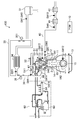
- FIG. 1 is a schematic diagram showing the configuration of a spark ignition direct injection engine.
- FIG. 2 is a block diagram relating to the control of the spark ignition direct injection engine.
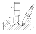
- FIG. 3 is an enlarged cross-sectional view showing the combustion chamber.
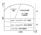
- FIG. 4 is a diagram illustrating an engine operating region.
- FIG. 5A illustrates an example of the fuel injection timing when the intake stroke injection is performed in the CI mode and the heat generation rate of the CI combustion associated therewith.
- FIG. 5B is an example of the fuel injection timing when performing high-pressure retarded injection in the CI mode, and the heat generation rate of CI combustion associated therewith.
- FIG. 5C is an example of the fuel injection timing and ignition timing when high pressure retarded injection is performed in the SI mode, and the heat generation rate of SI combustion associated therewith.
- FIG. 5D is an example of the fuel injection timing and ignition timing when performing split injection of intake stroke injection and high pressure retarded injection in the SI mode, and the heat generation rate of SI combustion associated therewith.
- FIG. 6 is a diagram comparing the state of SI combustion by high-pressure retarded injection and the state of conventional SI combustion.
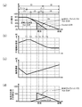
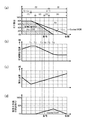
- FIG. 7 shows changes in (a) the gas composition in the cylinder, (b) the compression start temperature, (c) the oxygen concentration, and (d) the external EGR ratio during intake with respect to the difference in engine load.
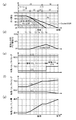
- FIG. 8 shows (a) the gas composition in the cylinder, (d) the ratio of external EGR during intake, (e) the exhaust valve timing, (f) the intake valve timing, and (g) the intake valve lift amount with respect to the engine load difference.
- FIG. 9 shows (a) the gas composition in the cylinder, (d) the ratio of the external EGR during intake, (h) the throttle opening, (i) the EGR valve opening, (j) the EGR cooler bypass valve with respect to the engine load difference. It is a change in opening.
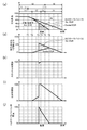
- FIG. 10 shows changes in (a) gas composition in the cylinder, (k) fuel injection start timing, (l) fuel pressure, and (m) ignition timing with respect to differences in engine load.
- FIG. 11 is a diagram showing the relationship between the opening / closing timing of the intake / exhaust valve and the internal EGR rate.
- FIG. 12 is a diagram showing the relationship between the EGR rate and the engine load at a predetermined rotational speed.
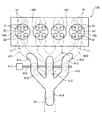
- FIG. 13 is a schematic view showing a configuration of a spark ignition direct injection engine having a configuration different from that of FIG.
- FIG. 14 is a side view showing the configuration of the exhaust manifold of the spark ignition direct injection engine shown in FIG.
- FIG. 15 is a side view showing a configuration of an independent exhaust passage provided in the exhaust manifold of the spark ignition direct injection engine shown in FIG. 16 is a side view showing a configuration of a bypass passage provided in an exhaust manifold of the spark ignition direct injection engine shown in FIG. 17 is a cross-sectional view taken along line AA in FIG.
- FIG. 18 is a block diagram relating to control of the spark ignition direct injection engine shown in FIG.
- FIG. 19 shows (a) the gas composition in the cylinder, (b) the compression start temperature, (c) the oxygen concentration, and (d) the outside during intake in the spark ignition direct injection engine shown in FIG. This is a change in the EGR ratio.
- FIG. 20 shows (a) the gas composition in the cylinder, (d) the ratio of external EGR during intake, (e) the exhaust valve timing, (f) in the spark ignition direct injection engine shown in FIG. Intake valve timing, (g) Changes in intake valve lift amount.
- FIG. 21 shows (a) the gas composition in the cylinder, (d) the ratio of the external EGR during intake, (h) the throttle opening, (i) in the spark ignition direct injection engine shown in FIG. EGR valve opening, (j) change in flow switching valve opening.
- FIG. 20 shows (a) the gas composition in the cylinder, (d) the ratio of the external EGR during intake, (h) the throttle opening, (i) in the spark ignition direct injection engine shown in FIG. EGR valve opening, (j) change in
- FIG. 22 is a block diagram relating to the control of a spark ignition direct injection engine having a configuration different from that of FIGS. 2 and 18.
- FIG. 23 shows (a) the gas composition in the cylinder, (d) the ratio of external EGR during intake, (e) the exhaust valve timing, (f) in the spark ignition direct injection engine shown in FIG. Intake valve timing, (g) Changes in intake valve lift amount.
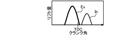
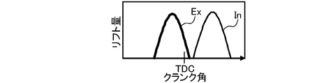
- FIG. 24A is a diagram illustrating the valve opening characteristics of the intake valve and the exhaust valve in the load region from the minimum load to the load T1.
- FIG. 24B is a diagram illustrating valve opening characteristics of the intake valve and the exhaust valve in a load region from loads T1 to T3.
- FIG. 24A is a diagram illustrating the valve opening characteristics of the intake valve and the exhaust valve in a load region from loads T1 to T3.
- 24C is a diagram illustrating the valve opening characteristics of the intake and exhaust valves in the load region from loads T3 to T5.
- FIG. 24D is a diagram illustrating the valve opening characteristics of the intake valve and the exhaust valve in a load region from loads T5 to T6.
- FIG. 24E is a diagram illustrating the valve opening characteristics of the intake valve and the exhaust valve in a high load region exceeding the load T6.
- the engine 1 is a spark ignition gasoline engine that is mounted on a vehicle and supplied with fuel containing at least gasoline.
- the engine 1 includes a cylinder block 11 provided with a plurality of cylinders 18 (only one cylinder is shown in FIG. 1, but four cylinders are provided in series, for example), and the cylinder block 11 is arranged on the cylinder block 11.
- the cylinder head 12 is provided, and an oil pan 13 is provided below the cylinder block 11 and stores lubricating oil.
- a piston 14 connected to the crankshaft 15 via a connecting rod 142 is fitted in each cylinder 18 so as to be able to reciprocate.
- a cavity 141 like a reentrant type in a diesel engine is formed on the top surface of the piston 14 as shown in an enlarged view in FIG.
- the cavity 141 is opposed to an injector 67 described later when the piston 14 is positioned near the compression top dead center.
- the cylinder head 12, the cylinder 18, and the piston 14 having the cavity 141 define a combustion chamber 19.
- the shape of the combustion chamber 19 is not limited to the illustrated shape.
- the shape of the cavity 141, the top surface shape of the piston 14, the shape of the ceiling portion of the combustion chamber 19, and the like can be changed as appropriate.
- This engine 1 is set to a relatively high geometric compression ratio of 15 or more for the purpose of improving theoretical thermal efficiency, stabilizing compression ignition combustion, which will be described later, and the like. In addition, what is necessary is just to set a geometric compression ratio suitably in the range of about 15-20.
- the cylinder head 12 is provided with an intake port 16 and an exhaust port 17 for each cylinder 18.
- the intake port 16 and the exhaust port 17 have an intake valve 21 and an exhaust for opening and closing the opening on the combustion chamber 19 side.
- Each valve 22 is disposed.
- VVL Vehicle Valve Lift
- FIG. 2 a hydraulically operated variable mechanism
- VVL (Variable Valve Lift) 71 is provided. Although the detailed illustration of the configuration of the VVL 71 is omitted, two types of cams having different cam profiles, a first cam having one cam peak and a second cam having two cam peaks, and the first And a lost motion mechanism that selectively transmits an operating state of one of the second cams to the exhaust valve.
- the exhaust valve 22 When the operating state of the first cam is transmitted to the exhaust valve 22, the exhaust valve 22 operates in the normal mode in which the valve is opened only once during the exhaust stroke, whereas the operating state of the second cam is the exhaust valve.
- the exhaust valve 22 When transmitting to the engine 22, the exhaust valve 22 operates in a special mode in which the exhaust valve is opened during the exhaust stroke and is also opened during the intake stroke so that the exhaust is opened twice.
- the normal mode and the special mode of the VVL 71 are switched according to the operating state of the engine. Specifically, the special mode is used in the control related to the internal EGR.
- operating the VVL 71 in the normal mode and not opening the exhaust twice is referred to as “turning off the VVL 71”, and operating the VVL 71 in the special mode and opening the exhaust twice. , “Turn on VVL 71”.
- an electromagnetically driven valve system that drives the exhaust valve 22 by an electromagnetic actuator may be employed.
- the execution of the internal EGR is not realized only by opening the exhaust gas twice.
- the internal EGR control may be performed by opening the intake valve 21 twice or by opening the intake valve twice, or by providing a negative overlap period in which both the intake valve 21 and the exhaust valve 22 are closed in the exhaust stroke or the intake stroke.
- Internal EGR control that causes the fuel gas to remain in the cylinder 18 may be performed.
- the exhaust side valve system having the VVL 71 is arranged on the intake side as shown in FIG. 2.
- 72 and a lift variable mechanism (hereinafter referred to as CVVL (Continuously Variable Variable)) 73 capable of continuously changing the lift amount of the intake valve 21 are provided.
- the VVT 72 may employ a hydraulic, electromagnetic, or mechanical structure as appropriate, and illustration of the detailed structure is omitted.
- the CVVL 73 can also adopt various known structures as appropriate, and the detailed structure is not shown.
- the intake valve 21 can change its valve opening timing, valve closing timing, and lift amount.
- the cylinder head 12 is also provided with an injector 67 for each cylinder 18 for directly injecting fuel into the cylinder 18.
- the injector 67 is disposed so that its nozzle hole faces the inside of the combustion chamber 19 from the central portion of the ceiling surface of the combustion chamber 19.
- the injector 67 directly injects an amount of fuel into the combustion chamber 19 at an injection timing set according to the operating state of the engine 1 and according to the operating state of the engine 1.
- the injector 67 is a multi-hole injector having a plurality of nozzle holes, although detailed illustration is omitted. Thereby, the injector 67 injects the fuel so that the fuel spray spreads radially from the center position of the combustion chamber 19. As indicated by the arrows in FIG.
- the fuel spray injected radially from the central portion of the combustion chamber 19 at the timing when the piston 14 is located near the compression top dead center is a cavity formed on the top surface of the piston. It flows along the wall surface of 141. It can be paraphrased that the cavity 141 is formed so that the fuel spray injected at the timing when the piston 14 is located near the compression top dead center is contained therein.
- This combination of the multi-hole injector 67 and the cavity 141 is an advantageous configuration for shortening the mixture formation period and the combustion period after fuel injection.
- the injector 67 is not limited to a multi-hole injector, and may be an outside-opening type injector.
- the fuel tank (not shown) and the injector 67 are connected to each other by a fuel supply path.
- a fuel supply system 62 including a fuel pump 63 and a common rail 64 and capable of supplying fuel to the injector 67 at a relatively high fuel pressure is interposed on the fuel supply path.
- the fuel pump 63 pumps fuel from the fuel tank to the common rail 64, and the common rail 64 can store the pumped fuel at a relatively high fuel pressure.
- the fuel pump 63 is a plunger type pump and is driven by the engine 1.
- the fuel supply system 62 configured to include this engine-driven pump enables the fuel with a high fuel pressure of 30 MPa or more to be supplied to the injector 67.
- the fuel pressure may be set to about 120 MPa at the maximum.
- the pressure of the fuel supplied to the injector 67 is changed according to the operating state of the engine 1 as will be described later.
- the fuel supply system 62 is not limited to this configuration.
- a spark plug 25 that ignites the air-fuel mixture in the combustion chamber 19 is attached to the cylinder head 12.
- the spark plug 25 is disposed through the cylinder head 12 so as to extend obliquely downward from the exhaust side of the engine 1.
- the tip of the spark plug 25 is disposed facing the cavity 141 of the piston 14 located at the compression top dead center.
- an intake passage 30 is connected to one side of the engine 1 so as to communicate with the intake port 16 of each cylinder 18.
- an exhaust passage 40 for discharging burned gas (exhaust gas) from the combustion chamber 19 of each cylinder 18 is connected to the other side of the engine 1.
- an air cleaner 31 for filtering the intake air is disposed at the upstream end of the intake passage 30, an air cleaner 31 for filtering the intake air is disposed.
- a surge tank 33 is disposed near the downstream end of the intake passage 30.
- the intake passage 30 on the downstream side of the surge tank 33 is an independent passage branched for each cylinder 18, and the downstream end of each independent passage is connected to the intake port 16 of each cylinder 18.
- a water-cooled intercooler / warmer 34 that cools or heats the air and a throttle valve 36 that adjusts the amount of intake air to each cylinder 18 are arranged. It is installed.
- An intercooler bypass passage 35 that bypasses the intercooler / warmer 34 is also connected to the intake passage 30.
- the intercooler bypass passage 35 is connected to an intercooler for adjusting the flow rate of air passing through the passage 35.
- a bypass valve 351 is provided. Adjusting the temperature of fresh air introduced into the cylinder 18 by adjusting the ratio between the passage flow rate of the intercooler bypass passage 35 and the passage flow rate of the intercooler / warmer 34 through the opening degree adjustment of the intercooler bypass valve 351. Is possible.
- the upstream portion of the exhaust passage 40 is constituted by an exhaust manifold having an independent passage branched for each cylinder 18 and connected to the outer end of the exhaust port 17 and a collecting portion where the independent passages gather.
- a direct catalyst 41 and an underfoot catalyst 42 are connected downstream of the exhaust manifold in the exhaust passage 40 as exhaust purification devices for purifying harmful components in the exhaust gas.
- Each of the direct catalyst 41 and the underfoot catalyst 42 includes a cylindrical case and, for example, a three-way catalyst disposed in a flow path in the case.
- the EGR passage 50 includes a main passage 51 in which an EGR cooler 52 for cooling the exhaust gas with engine coolant is disposed, and an EGR cooler bypass passage 53 for bypassing the EGR cooler 52. ing.
- the main passage 51 is provided with an EGR valve 511 for adjusting the amount of exhaust gas recirculated to the intake passage 30, and the EGR cooler bypass passage 53 has a flow rate of exhaust gas flowing through the EGR cooler bypass passage 53.
- An EGR cooler bypass valve 531 for adjustment is provided.
- the engine 1 configured as described above is controlled by a powertrain control module (hereinafter referred to as PCM) 10.
- the PCM 10 includes a microprocessor having a CPU, a memory, a counter timer group, an interface, and a path connecting these units. This PCM 10 constitutes a controller.
- detection signals of various sensors SW1 to SW16 are input to the PCM 10.
- the various sensors include the following sensors. That is, the air flow sensor SW1 that detects the flow rate of fresh air, the intake air temperature sensor SW2 that detects the temperature of fresh air, the downstream side of the intercooler / warmer 34, and the intercooler / warmer 34 downstream of the air cleaner 31.
- a second intake air temperature sensor SW3 for detecting the temperature of fresh air after passing through the EGR gas temperature sensor SW4 which is disposed in the vicinity of the connection portion of the EGR passage 50 with the intake passage 30 and detects the temperature of the external EGR gas.
- An intake port temperature sensor SW5 that is attached to the intake port 16 and detects the temperature of the intake air just before flowing into the cylinder 18, and an in-cylinder pressure sensor SW6 that is attached to the cylinder head 12 and detects the pressure in the cylinder 18.
- the exhaust passage 40 is disposed in the vicinity of the connection portion of the EGR passage 50 and has an exhaust temperature and exhaust gas Exhaust temperature sensor SW7 and exhaust pressure sensor SW8 for detecting a force, and is disposed on the upstream side of the direct catalyst 41, the linear O 2 sensor SW9, direct catalyst 41 and underfoot catalyst 42 for detecting the oxygen concentration in the exhaust gas
- the lambda O 2 sensor SW10 that detects the oxygen concentration in the exhaust gas, the water temperature sensor SW11 that detects the temperature of the engine coolant, the crank angle sensor SW12 that detects the rotation angle of the crankshaft 15, and the vehicle
- An accelerator opening sensor SW13 for detecting an accelerator opening corresponding to an operation amount of an accelerator pedal (not shown), intake-side and exhaust-side cam angle sensors SW14, SW15
- the PCM 10 performs various calculations based on these detection signals to determine the state of the engine 1 and the vehicle, and accordingly, the injector 67, the spark plug 25, the intake valve side VVT 72 and CVVL 73, and the exhaust valve side Control signals are output to the actuators of the VVL 71, the fuel supply system 62, and various valves (throttle valve 36, intercooler bypass valve 351, EGR valve 511, and EGR cooler bypass valve 531).
- the PCM 10 operates the engine 1.
- FIG. 4 shows an example of the operation region of the engine 1.
- This engine 1 is a compression ignition combustion in which combustion is performed by compression self-ignition without ignition by the spark plug 25 in a low load region where the engine load is relatively low for the purpose of improving fuel consumption and exhaust emission performance. I do.
- the compression ignition combustion becomes too steep and causes problems such as combustion noise. Therefore, in the engine 1, in a high load region where the engine load is relatively high, the compression ignition combustion is stopped, and the engine 1 is switched to the spark ignition combustion using the spark plug 25.
- the engine 1 has a CI (Compression Ignition) mode in which compression ignition combustion is performed and an SI (Spark Ignition) mode in which spark ignition combustion is performed according to the operating state of the engine 1, in particular, the load of the engine 1. It is configured to switch.
- CI Compression Ignition
- SI Spark Ignition
- the boundary line for mode switching is not limited to the illustrated example.
- CI mode is further divided into three areas according to the engine load. Specifically, in the region (1) where the load is the lowest in the CI mode, hot EGR gas having a relatively high temperature is introduced into the cylinder 18 in order to improve the ignitability and stability of the compression ignition combustion. As will be described in detail later, this is because the VVL 71 is turned on and the exhaust valve 22 is opened twice during the intake stroke. The introduction of hot EGR gas is advantageous in increasing the compression end temperature in the cylinder 18 and improving the ignitability and stability of the compression ignition combustion in the light load region (1). In the region (1), as shown in FIG.
- the injector 67 injects fuel into the cylinder 18 at least during the period from the intake stroke to the middle of the compression stroke, thereby forming a homogeneous lean air-fuel mixture.
- the excess air ratio ⁇ of the air-fuel mixture may be set to, for example, 2.4 or more. By doing so, it is possible to suppress the generation of RawNOx and improve the exhaust emission performance. Then, as shown in FIG. 5A, the lean air-fuel mixture undergoes compression self-ignition near the compression top dead center.
- the air-fuel ratio of the air-fuel mixture is set to the stoichiometric air-fuel ratio ( ⁇ 1).
- a three-way catalyst can be used, and as will be described later, control at the time of switching between the SI mode and the CI mode is simplified, and the CI mode is further expanded to the high load side. It also contributes to making it possible.
- the temperature in the cylinder 18 naturally increases as the engine load increases, so the hot EGR gas amount is reduced to avoid pre-ignition. Although this will be described in detail later, this is due to the adjustment of the amount of internal EGR gas introduced into the cylinder 18. Further, the hot EGR gas amount may be adjusted by adjusting the external EGR gas amount bypassing the EGR cooler 52.
- cooled EGR gas having a relatively low temperature is introduced into the cylinder 18.
- the compression end temperature in the cylinder 18 is made appropriate, and the rapid ignition while ensuring the ignitability of the compression ignition. Avoid combustion and stabilize compression ignition combustion.
- the EGR rate as a ratio of the EGR gas introduced into the cylinder 18 including the hot EGR gas and the cooled EGR gas is as high as possible under the condition that the air-fuel ratio of the air-fuel mixture is set to ⁇ 1. Set to rate. Therefore, in the region (2), the fuel injection amount increases as the engine load increases, so the EGR rate gradually decreases.
- the compression end temperature in the cylinder 18 is further increased. Therefore, as in the region (1) and the region (2) In addition, if fuel is injected into the cylinder 18 during the period from the intake stroke to the middle of the compression stroke, abnormal combustion such as pre-ignition occurs. On the other hand, if a large amount of cooled EGR gas having a low temperature is introduced to lower the compression end temperature in the cylinder, the ignitability of the compression ignition is deteriorated.
- a fuel injection mode Stabilize compression ignition combustion while avoiding abnormal combustion such as ignition.
- this fuel injection mode at least a period from the latter stage of the compression stroke to the initial stage of the expansion stroke (hereinafter, this period is referred to as retarded) with a fuel pressure that is significantly higher than that of the conventional fuel injection mode.
- the fuel is injected into the cylinder 18 within a period).
- This characteristic fuel injection mode is hereinafter referred to as “high pressure retarded injection” or simply “retarded injection”.
- high-pressure retarded injection stabilizes compression ignition combustion while avoiding abnormal combustion in the region (3). Details of the high-pressure retarded injection will be described later.
- the SI mode is divided into two regions, region (4) and region (5), according to the engine speed. ing.
- the region (4) corresponds to a low speed region when the operation region of the engine 1 is divided into a low speed and a high speed in the illustrated example
- the region (5) corresponds to a high speed region.
- the boundary between the region (4) and the region (5) is also inclined in the rotational speed direction with respect to the load level in the operation region shown in FIG. 4, but the boundary between the region (4) and the region (5) Is not limited to the illustrated example.
- the air-fuel mixture is set to the stoichiometric air-fuel ratio ( ⁇ 1) similarly to the region (2) and the region (3). Therefore, the air-fuel ratio of the air-fuel mixture is made constant at the theoretical air-fuel ratio ( ⁇ 1) across the boundary between the CI mode and the SI mode. This allows the use of a three-way catalyst.
- the throttle valve 36 is fully opened, and the fresh air introduced into the cylinder 18 by adjusting the opening of the EGR valve 511. Adjust the amount and external EGR gas amount.
- Adjusting the gas ratio introduced into the cylinder 18 in this way reduces pump loss and introduces a large amount of EGR gas into the cylinder 18, thereby suppressing the combustion temperature of spark ignition combustion and reducing cooling loss.
- the external EGR gas cooled mainly through the EGR cooler 52 is introduced into the cylinder 18. This is advantageous for avoiding abnormal combustion, and also has an advantage of suppressing generation of Raw soot NOx.
- the external EGR is set to zero by closing the EGR valve 511.
- the geometric compression ratio of the engine 1 is set to 15 or more (for example, 18) as described above. Since the high compression ratio increases the compression end temperature and the compression end pressure, it is advantageous for stabilizing the compression ignition combustion in the CI mode, particularly in a low load region (for example, the region (1)). On the other hand, the high compression ratio engine 1 has a problem that abnormal combustion such as pre-ignition and knocking is likely to occur in the SI mode which is a high load region.
- abnormal combustion is avoided by performing the high-pressure retarded injection described above in the SI mode region (4) and region (5). More specifically, in the region (4), as shown in FIG. 5C, fuel injection is performed in the cylinder 18 in the retard period from the latter stage of the compression stroke to the early stage of the expansion stroke with a high fuel pressure of 30 MPa or more. Only high-pressure retarded injection is performed. On the other hand, in the region (5), as shown in FIG. 5D, a part of the fuel to be injected is injected into the cylinder 18 within the intake stroke period in which the intake valve 21 is open, and the remaining fuel is injected. Fuel is injected into the cylinder 18 within the retard period. That is, in the region (5), fuel split injection is performed.
- the intake stroke period during which the intake valve 21 is open is not a period defined based on the piston position, but a period defined based on opening / closing of the intake valve, and the intake stroke referred to here is CVVL73.
- the piston may deviate from the time when the piston reaches the bottom dead center of the intake.
- FIG. 6 shows the heat generation rate (upper diagram) and the progress of the unburned mixture reaction in the SI combustion (solid line) by the high pressure retarded injection described above and the conventional SI combustion (broken line) in which fuel injection is performed during the intake stroke. It is a figure which compares the difference in a degree (lower figure).
- the horizontal axis in FIG. 6 is the crank angle.
- the operating state of the engine 1 is both a high-load low-speed region (that is, region (4)), and the amount of fuel to be injected is the case of SI combustion by high-pressure retarded injection and conventional SI combustion. They are the same as each other.
- a predetermined amount of fuel is injected into the cylinder 18 during the intake stroke (broken line in the upper diagram).
- a relatively homogeneous air-fuel mixture is formed after the fuel injection until the piston 14 reaches the compression top dead center.
- ignition is executed at a predetermined timing indicated by a white circle after the compression top dead center, thereby starting combustion.
- the combustion ends through a peak of the heat generation rate.
- the time from the start of fuel injection to the end of combustion corresponds to the reaction possible time of the unburned mixture (hereinafter sometimes simply referred to as reaction possible time).
- reaction possible time As shown by the broken line in the lower diagram of FIG.
- the reaction of the fuel mixture gradually proceeds.
- the dotted line in the figure shows the ignition threshold, which is the reactivity with which the unburned mixture reaches ignition, and the conventional SI combustion has a very low reaction time in combination with the low speed range.
- the reaction of the unburned mixture continues to progress during that time, so the reactivity of the unburned mixture exceeds the ignition threshold before and after ignition, and abnormal combustion such as premature ignition or knocking occurs. cause.
- high-pressure retarded injection aims to shorten the reaction time and thereby avoid abnormal combustion. That is, as shown in FIG. 6, the possible reaction time is a period during which the injector 67 injects fuel ((1) injection period), and after the injection is completed, a combustible mixture is formed around the spark plug 25. (2) The mixture formation period) and the period until the combustion started by ignition is completed ((3) combustion period), that is, (1) + (2 ) + (3).
- the high-pressure retarded injection shortens the injection period, the mixture formation period, and the combustion period, thereby shortening the reaction time. This will be described in order.
- the high fuel pressure relatively increases the amount of fuel injected from the injector 67 per unit time. For this reason, when the fuel injection amount is constant, the relationship between the fuel pressure and the fuel injection period is generally such that the lower the fuel pressure, the longer the injection period, and the higher the fuel pressure, the shorter the injection period. Therefore, the high pressure retarded injection in which the fuel pressure is set to be significantly higher than the conventional one shortens the injection period.
- the high fuel pressure is advantageous for atomizing the fuel spray injected into the cylinder 18 and makes the flight distance of the fuel spray longer. For this reason, the relationship between the fuel pressure and the fuel evaporation time is generally longer as the fuel pressure is lower, and the fuel evaporation time is longer as the fuel pressure is higher. Further, the time until the fuel spray reaches the fuel pressure and the spark plug 25 is generally longer as the fuel pressure is lower, and the time until the fuel spray is higher as the fuel pressure is higher.
- the air-fuel mixture formation period is a time obtained by adding the fuel evaporation time and the fuel spray arrival time around the spark plug 25. Therefore, the higher the fuel pressure, the shorter the air-fuel mixture formation period.
- the high pressure retarded injection in which the fuel pressure is set to be significantly higher than the conventional case shortens the mixture formation period as a result of the fuel evaporation time and the fuel spray arrival time around the spark plug 25 being reduced.
- the conventional intake stroke injection at a low fuel pressure significantly increases the mixture formation period.
- the combination of the multi-injector type injector 67 and the cavity 141 shortens the time until fuel spray reaches around the spark plug 25 after fuel injection. Effective for shortening.
- shortening the injection period and the mixture formation period makes it possible to set the fuel injection timing, more precisely, the injection start timing to a relatively late timing. Therefore, in the high pressure retarded injection, as shown in the upper diagram of FIG. 6, fuel injection is performed within the retard period from the latter stage of the compression stroke to the early stage of the expansion stroke. As the fuel is injected into the cylinder 18 at a high fuel pressure, the turbulence in the cylinder becomes stronger and the turbulence energy in the cylinder 18 increases. This high turbulence energy is a timing at which the fuel injection timing is relatively late. Therefore, it is advantageous for shortening the combustion period.
- the relationship between the fuel pressure and the turbulent energy in the combustion period is generally lower as the fuel pressure is lower and the turbulent energy is lower as the fuel pressure is higher. Becomes higher.
- the injection timing is in the intake stroke, the time until the ignition timing is long, or the cylinder 18 is in the compression stroke after the intake stroke. Due to the compression of the inside, the disturbance in the cylinder 18 is attenuated.
- the turbulent energy during the combustion period becomes relatively low regardless of the fuel pressure level.
- the relationship between the turbulent energy and the combustion period in the combustion period is such that the lower the turbulent energy, the longer the combustion period, and the higher the turbulent energy, the shorter the combustion period. Therefore, the relationship between the fuel pressure and the combustion period is such that the lower the fuel pressure, the longer the combustion period, and the higher the fuel pressure, the shorter the combustion period. That is, the high pressure retarded injection shortens the combustion period.
- the conventional intake stroke injection at a low fuel pressure has a longer combustion period.
- the multi-injector type injector 67 is advantageous for improving the turbulent energy in the cylinder 18 and is effective for shortening the combustion period.
- the combination of the multi-injector type injector 67 and the cavity 141 provides fuel. Putting the spray in the cavity 141 is also effective for shortening the combustion period.
- the high pressure retarded injection shortens the injection period, the mixture formation period, and the combustion period, and as a result, as shown in FIG. 6, the fuel injection start timing SOI to the combustion end timing ⁇ end are not changed. It is possible to significantly shorten the reaction time of the fuel mixture as compared with the case of fuel injection during the conventional intake stroke. As a result of shortening this reaction possible time, as shown in the upper diagram of FIG. 6, in the conventional intake stroke injection at a low fuel pressure, as shown by a white circle, the reaction progress of the unburned mixture at the end of combustion is shown.
- the high-pressure retarded injection suppresses the progress of the reaction of the unburned mixture at the end of combustion, as shown by the black circle, to prevent abnormal combustion. It can be avoided. It should be noted that the ignition timing is set to the same timing in the white circle and the black circle in the upper diagram of FIG.
- the fuel pressure is set to, for example, 30 MPa or more.
- the fuel pressure of 30 MPa or more can effectively shorten the injection period and the mixture formation period, respectively.
- the fuel pressure is preferably set as appropriate according to the properties of the fuel used, which contains at least gasoline.
- the upper limit may be 120 MPa as an example.
- High pressure retarded injection avoids the occurrence of abnormal combustion in the SI mode by devising the form of fuel injection into the cylinder 18. Unlike this, it is conventionally known that the ignition timing is retarded for the purpose of avoiding abnormal combustion. The retarding of the ignition timing suppresses the progress of the reaction by suppressing the increase in the temperature and pressure of the unburned mixture. However, retarding the ignition timing leads to a decrease in thermal efficiency and torque, whereas when performing high-pressure retarded injection, the ignition timing can be advanced by an amount that avoids abnormal combustion by devising the form of fuel injection. Since it is possible, thermal efficiency and torque are improved. That is, the high pressure retarded injection not only avoids abnormal combustion, but also makes it possible to advance the ignition timing by the amount that can be avoided, which is advantageous in improving fuel consumption.
- the high pressure retarded injection in the SI mode can shorten the injection period, the mixture formation period, and the combustion period, but the high pressure retarded injection performed in the CI mode region (3) It is possible to shorten the injection period and the mixture formation period.
- the turbulence in the cylinder 18 is increased by injecting the fuel into the cylinder 18 at a high fuel pressure, so that the mixing performance of the atomized fuel is increased and the fuel is injected at a late timing near the compression top dead center.
- a relatively homogeneous air-fuel mixture can be quickly formed.
- the high pressure retarded injection in the SI mode shortens the reaction time of the unburned mixture by performing the fuel injection within the retard period.
- the actual time for the crank angle change is long, which is effective.
- the high speed range where the engine 1 has a relatively high rotational speed Not very effective due to short time.
- the retard injection since the fuel injection timing is set near the compression top dead center, in-cylinder gas not containing fuel, in other words, air having a high specific heat ratio is compressed in the compression stroke.
- the compression end temperature in the cylinder 18 becomes high, and this high compression end temperature causes knocking. Therefore, when only the retard injection is performed in the region (5), it may occur that the ignition timing must be retarded to avoid knocking.
- the turbulence increases in the cylinder 18 (combustion chamber 19) near the compression top dead center, and the combustion period is shortened. This is also advantageous in suppressing knocking, and the ignition timing can be further advanced.
- the region (5) by performing split injection of intake stroke injection and high pressure retarded injection, it is possible to improve thermal efficiency while avoiding abnormal combustion.
- a multi-point ignition configuration may be adopted instead of performing high pressure retarded injection. That is, a plurality of ignition plugs are arranged facing the combustion chamber, and in the region (5), the intake stroke injection is executed and each of the plurality of ignition plugs is driven to perform multipoint ignition. By doing so, since the flame spreads from each of the plurality of fire types in the combustion chamber 19, the flame spreads quickly and the combustion period is shortened. As a result, the combustion period is shortened similarly to the case where high pressure retarded injection is employed, which is advantageous for improving the thermal efficiency.
- the fuel pressure can be lowered. This is advantageous in improving fuel consumption because the driving force of the fuel pump 63 driven by the engine 1 is reduced.
- FIG. 7 to 10 show examples of control of each parameter of the engine 1 with respect to the engine load in the low speed range.
- the change in load in the direction from the low load to the high load is shown in the engine operation map shown in FIG. Is exemplified by a dashed-dotted arrow.
- FIG. 7A to 7D relate to the state in the cylinder 18,
- FIG. 7A shows the gas composition (gas ratio) in the cylinder 18, and
- FIG. 7B shows the inside of the cylinder 18 at the start of compression.
- (C) in FIG. 2 shows the oxygen concentration.
- FIG. 7D shows the ratio of external EGR during intake, which can be said to be the amount obtained by removing the internal EGR gas from the EGR gas introduced into the cylinder 18.
- FIGS. 7 (a) and 7 (d) are the same as FIGS. 7 (a) and 7 (d) and show the gas composition in the cylinder 18 and the external EGR ratio during intake, respectively.
- 8 (e) to 8 (g) relate to the control of the valve operating system, FIG. 8 (e) shows the opening / closing timing of the exhaust valve 22, FIG. 8 (f) shows the opening / closing timing of the intake valve 21, and FIG. g) is the lift amount of the intake valve.
- FIGS. 7 (a) and 7 (d) are the same as FIGS. 7 (a) and 7 (d).
- 9 (h) to 9 (j) relate to the control of the intake / exhaust system
- FIG. 9 (h) shows the opening of the throttle valve 36
- FIG. 9 (i) shows the opening of the EGR valve 511
- FIG. j) shows the opening of the EGR cooler bypass valve 531.
- FIG. 10A is also the same as FIG. 7A and shows the gas composition in the cylinder 18.
- 10 (k) to 10 (m) relate to the control of the fuel injection and ignition system, FIG. 10 (k) shows the injection start timing, FIG. 10 (l) shows the fuel pressure, and FIG. 10 (m) shows the ignition timing. Respectively.
- FIG. 7A shows the state in the cylinder 18 as described above, and the area on the left side of the figure in which the load is relatively low is the CI mode, and the load on the right side of the figure is higher than the predetermined load. The area is in SI mode.
- the fuel amount (total fuel amount) injected into the cylinder 18 is increased as the load increases regardless of the CI mode and the SI mode.
- a lean air-fuel mixture with an excess air ratio ⁇ ⁇ 2.4 may be used, which is in combination with introducing a large amount of EGR gas into the cylinder 18.
- the generation of RawNOx is suppressed.
- Introducing a large amount of EGR gas into the cylinder 18 is also advantageous in reducing pump loss.
- fuel injection is executed within the intake stroke period at a relatively low fuel pressure.
- a low fuel pressure is advantageous for improving fuel consumption.
- the fuel pressure gradually increases as the engine load increases.
- a large amount of internal EGR gas is introduced into the cylinder 18, and as shown in FIG.
- the compression end temperature is increased, which is advantageous for improving the ignitionability of compression ignition and improving the stability of compression ignition combustion.
- the oxygen concentration gradually decreases as the load increases.
- the intercooler / warmer 34 warms the intercooler bypass valve 351 by closing it. The generated fresh air may be introduced into the cylinder 18.
- the air-fuel ratio of the air-fuel mixture is set to the stoichiometric air-fuel ratio ( ⁇ 1). Therefore, as the amount of injected fuel increases, the amount of fresh air introduced into the cylinder 18 also increases, and the EGR rate decreases accordingly (see FIG. 7A). Even at the predetermined loads T1 to T2, fuel injection is performed within the intake stroke period at a relatively low fuel pressure (see FIGS. 10 (k) and (l)).
- the throttle opening is basically fully open.
- the lift amount of the intake valve 21 is adjusted to be introduced into the cylinder 18. The amount of fresh air and the amount of internal EGR gas are adjusted.
- the valve opening period of the intake valve 21 and the opening of the exhaust valve 22 when the exhaust valve 22 is opened twice are opened. Since the overlap with the period changes, the internal EGR rate decreases. Note that the closing timing of the intake valve 21 is made substantially constant even if the lift amount of the intake valve 21 changes. If the lift amount of the intake valve 21 is continuously changed by the control of the CVVL 73 and the VVT 72, the internal EGR rate can be continuously reduced. Between the predetermined loads T1 and T2, the intake valve is arranged so that the EGR rate is maximized while maintaining the theoretical air-fuel ratio ⁇ 1, in other words, as much internal EGR gas as possible is introduced into the cylinder 18. The lift amount of 21 is controlled. Specifically, as shown in FIGS. 8E, 8F, and 8G, the lift amount of the intake valve 21 is gradually increased, and the valve opening timing (IVO) of the intake valve 21 is gradually advanced accordingly. .
- the engine load equal to or higher than the predetermined load T2 corresponds to the region (2) in the operation map in FIG. 4, and there is a possibility that the temperature in the cylinder 18 becomes high and pre-ignition occurs. Therefore, when the engine load is equal to or higher than the predetermined load T2, the internal EGR gas amount is reduced, and the cooled external EGR gas is introduced into the cylinder 18 instead. That is, as shown in FIG. 9 (i), the opening degree of the EGR valve 511 is gradually increased from the closed state, and thereby the amount of external EGR gas cooled by passing through the EGR cooler 52 becomes the load of the engine 1. The amount is gradually increased along with the increase in. In addition, as shown in FIG.9 (j), the EGR cooler bypass valve 531 remains closed. Thus, the cooled external EGR gas (that is, cooled EGR gas) is gradually increased as the engine load increases (see also FIG. 7 (d)).
- the EGR rate including the internal EGR gas and the external EGR gas is equal to the stoichiometric air-fuel ratio ( ⁇ 1). Therefore, the load decreases at a predetermined rate with respect to the increase in load. For this reason, the internal EGR gas is reduced with an increase in load at a higher load side that is equal to or higher than the predetermined load T2 (that is, the slope in FIG. 7A increases).
- the lift amount of the intake valve 21 gradually increases as the load increases at a higher rate than the low load side up to the predetermined load T2. In response to this, the valve opening timing (IVO) of the intake valve 21 is gradually advanced.
- the temperature in the cylinder 18 gradually decreases as the load increases on the high load side of the predetermined load T2 or higher.
- the amount of internal EGR gas introduced is adjusted by adjusting the degree of overlap of the valve opening period of the intake valve 21 with respect to the valve opening period of the exhaust valve 22 opened within the intake stroke period. Basically, it is controlled by the intake CVVL 73. As shown by a solid line arrow in FIG. 11, the introduction amount of the internal EGR gas can be continuously reduced to a predetermined amount (see S1 and S2 in FIG. 11), but the opening period of the exhaust valve 22 is Since the adjustment cannot be made, if the introduction amount is to be reduced from the predetermined amount, the exhaust VVL 71 must be turned off and the exhaust double opening must be stopped. For this reason, as shown in S3 and S4 in the figure, as the exhaust VVL 71 is switched on / off, the amount of internal EGR gas introduced decreases discontinuously (see the dashed line arrow in FIG. 11). .
- the introduction of the internal EGR gas into the cylinder 18 is stopped at the predetermined load T3 in the region (2).
- an external EGR gas that is not cooled and bypasses the EGR cooler 52 is introduced into the cylinder 18.
- the exhaust VVL 71 is turned off to stop the opening of the exhaust twice, while the lift amount of the intake valve 21 is changed discontinuously and greatly.
- the valve opening timing is also greatly advanced near the intake top dead center. Note that at least on the high load side that is equal to or higher than the predetermined load T3 in the CI mode, the valve opening timing and the valve closing timing of the intake valve 21 and the exhaust valve 22 are held constant regardless of the increase in load.
- the opening degree of the EGR valve 511 is changed to fully open, and as shown in FIG. 9 (j), the opening degree of the EGR cooler bypass valve 531 is also changed to fully open. Further, as shown in FIG. 9 (h), the opening degree of the throttle valve 36 is temporarily reduced so that the EGR rate becomes higher than 50%. In this way, as shown in FIG. 9D, a predetermined amount of hot EGR gas (that is, external EGR gas that is not cooled) is introduced into the cylinder 18 at a predetermined load T3. In order to reduce the hot EGR gas as the engine load increases, as shown in FIG.
- the opening degree of the EGR cooler bypass valve 531 is gradually closed from fully opened on the high load side of the predetermined load T3 or higher.
- the opening degree of the throttle valve 36 is gradually changed to fully open while the EGR valve 511 is kept fully open.
- Predetermined loads T4 to T5 For engine loads exceeding the predetermined load T4 in the CI mode, adjusting the introduction ratio of the cooled EGR gas and the hot EGR gas alone can ensure the ignitability of compression ignition and avoid abnormal combustion such as premature ignition. Since it becomes difficult to achieve both, high-pressure retarded injection is performed as described above. This corresponds to the region (3) in the operation map of FIG.
- the fuel injection start time is largely changed from the time during the intake stroke in the regions (1) and (2) to the time near the compression top dead center. Further, the fuel pressure is also greatly changed from the low fuel pressure in the regions (1) and (2) to the high fuel pressure of 30 MPa or more as shown in FIG.
- the gas composition in the cylinder 18 continuously changes. 22
- the opening degree of the throttle valve 36, the opening degree of the EGR valve 511, and the opening degree of the EGR cooler bypass valve 531 do not change suddenly (FIGS. 8E, 8F, 8G). ), See FIG. 9 (h) (i) (j)). This is advantageous in suppressing the occurrence of a torque shock or the like during the transition between the region (2) and the region (3), and simplification of the control is achieved.
- the start timing of fuel injection as high pressure retarded injection on the high load side of the predetermined load T4 or higher is gradually retarded as the engine load increases, as shown in FIG.
- the fuel pressure is also set higher as the engine load increases, as shown in FIG. As the engine load increases, pre-ignition and the like are more likely to occur, and the pressure increase may become more severe. Therefore, these are effectively avoided by delaying the injection start timing of combustion and setting the fuel pressure higher.
- the opening degree of the throttle valve 36 is made fully open and constant (see (h) in FIG. 9), while the opening degree of the EGR valve 511 and the EGR cooler bypass valve 531 Each opening decreases as the engine load increases (see FIGS. 9 (i) and 9 (j)). Note that when the opening degree of the EGR valve 511 and the opening degree of the EGR cooler bypass valve 531 are compared, the opening rate of the EGR cooler bypass valve 531 is higher.
- the predetermined load T5 is related to switching between the CI mode and the SI mode, and the SI mode is set on the high load side exceeding the predetermined load T5. Since the air-fuel ratio of the air-fuel mixture is set to the stoichiometric air-fuel ratio ( ⁇ 1) on each of the low load side and the high load side across the boundary for switching between the CI mode and the SI mode, the EGR rate Is set to decrease continuously from the CI mode to the SI mode. This means that when switching from the CI mode to the SI mode where the combustion mode is switched, there is no significant change other than starting spark ignition, switching from the CI mode to the SI mode, or vice versa. Each can be made smooth to suppress the occurrence of torque shock or the like. In particular, since control responsiveness related to the recirculation of exhaust gas through the EGR passage 50 is relatively low, control that does not cause a sudden change in the EGR rate is advantageous in improving controllability.
- the EGR rate is set as high as possible, so that the EGR rate becomes high in the low load region near the boundary with the CI mode in the SI mode.
- a high EGR rate is advantageous for reducing pump loss, but may be disadvantageous for combustion stability in the SI mode.
- hot EGR gas is introduced into the cylinder 18 in the low load region in the SI mode, specifically, in the low load side of the predetermined load T6. That is, the external EGR gas that has passed through the EGR cooler bypass passage 53 and is not cooled is introduced into the cylinder 18.
- the temperature in the cylinder 18 is set higher, the ignition delay time is shortened, and the stability of the spark ignition combustion in the environment of the high EGR rate is improved. ing.
- the opening degree of the EGR valve 511 and the opening degree of the EGR cooler bypass valve 531 are gradually increased as the load increases so as to continue from the CI mode. Decrease.
- the cooled EGR gas increases, the hot EGR gas decreases, and the EGR rate including the cooled EGR gas and the hot EGR gas gradually decreases as the engine load increases. Accordingly, the amount of fresh air increases.
- the combustion stability is improved by increasing the temperature in the cylinder 18, so the EGR cooler bypass valve 531 is closed to make the hot EGR gas amount zero. At this time, the EGR valve 511 is open.
- the throttle valve opening is kept fully open between the predetermined loads T5 and T6 (see FIG. 9 (h)), and the opening timing and closing timing of the intake valve 21 and the exhaust valve 22 are also constant. (See FIGS. 8E, 8F, and 8G).
- the start timing of fuel injection is gradually retarded as the engine load increases, and the fuel pressure also increases as the engine load increases as shown in FIG. 10 (l). Increase gradually.
- the ignition timing gradually retards with the start of fuel injection as the engine load increases.
- spark ignition is performed by operating the spark plug 25 at a predetermined ignition timing in the low load side region of the predetermined loads T5 to T6, but the combustion mode is that a flame kernel is generated by spark ignition.
- the flame is not limited to the form in which the flame is propagated, and there may be a form in which the low-temperature oxidation reaction is promoted by spark ignition and self-ignition occurs.
- Predetermined load T6 or more In the SI mode, on the high load side above the predetermined load T6, the hot EGR gas amount becomes zero and only the cooled EGR gas is introduced into the cylinder 18 as shown in FIGS. Although illustration is omitted, on the high load side of the predetermined load T6 or higher, the intercooler bypass valve 351 is opened (for example, the opening degree is gradually increased in accordance with the increase in engine load), whereby the intercooler / warmer 34 is opened. The amount of fresh air that bypasses the engine may be increased, and the temperature of fresh air introduced into the cylinder 18 may be lowered. This is advantageous in avoiding abnormal combustion such as pre-ignition and knocking by lowering the temperature in the cylinder 18 in the high load side region.
- the opening degree of the throttle valve 36 is kept fully open, and as shown in FIG. 9 (i), the EGR valve 511 is gradually closed as the engine load increases and fully opened. Close the valve with a load. Therefore, the EGR rate becomes zero at the fully open load (see FIGS. 7A and 7D).
- the lift amount of the intake valve 21 is gradually increased as the engine load increases, and the maximum lift amount is obtained at the fully open load.
- the amount of fresh air introduced into the cylinder 18 is increased as the engine load increases, so that the torque on the high load side in the operating region of the engine 1 is improved.
- the fuel injection start timing is gradually retarded as the engine load increases, and the fuel pressure is also gradually set higher as the engine load increases.
- the ignition timing is gradually retarded as the engine load increases. Although abnormal combustion or the like tends to occur as the engine load increases, it is effectively avoided by retarding the eruption start timing and increasing the fuel pressure.
- FIG. 12 shows the relationship between the EGR rate and the engine load.
- the air-fuel ratio is set to lean in the light load region where the engine load is low, while in the region where the load is higher than the light load region, the engine load is high or the combustion mode is different. Regardless, the air-fuel ratio is set constant at the theoretical air-fuel ratio ( ⁇ 1).
- the engine 1 is controlled along a control line indicated by a thick solid arrow in FIG. 12, and the EGR rate is set to the maximum under the condition that the air-fuel ratio is set to the theoretical air-fuel ratio ( ⁇ 1). Therefore, the EGR rate changes continuously regardless of the engine load level and regardless of the switching of the combustion mode. This is advantageous in improving the controllability because the gas composition in the cylinder 18 continuously changes when the engine load changes continuously.
- FIG. 1 In a combustion mode in which compression ignition combustion is performed by introducing a fuel during the intake stroke while introducing a large amount of EGR gas into the cylinder 18 (that is, corresponding to the regions (1) and (2)), FIG. As indicated by the alternate long and short dash line, the engine load exceeding the predetermined value cannot be realized due to the restriction of dP / dt, but here, the fuel is injected at a high fuel pressure of 30 MPa or more and near the compression top dead center. By performing high-pressure retarded injection and introducing a relatively large amount of EGR gas into the cylinder 18, it is possible to perform compression ignition combustion stably while slowing the combustion and eliminating the restriction of dP / dt. become. This corresponds to the combustion mode of the region (3) in FIG. 4, and the CI mode can be expanded to the high load side. It can also be said that by providing this region (3), a continuous change in the EGR rate with respect to the engine load level is realized.
- high-pressure retarded injection is performed in the SI combustion region where the abnormal combustion such as pre-ignition (pre-ignition) may occur due to the high geometric compression ratio of the engine 1 (see the one-dot chain line in FIG. 12). By doing so, it is possible to avoid such abnormal combustion and perform stable spark ignition combustion.
- the high pressure retarded injection also enhances the combustion stability, and is advantageous in ensuring a predetermined combustion stability even when a high EGR rate is set at a load immediately after switching from the CI mode to the SI mode. This is also a factor that makes it possible to continuously change the EGR rate with respect to the engine load.
- the volume of the combustion chamber 19 becomes relatively small at the timing when the fuel is injected by high pressure retarded injection.
- high pressure retarded injection injects fuel into the cavity 141 at a high fuel pressure, thereby strengthening the flow in the cavity 141 and increasing the flow of air.
- Increase utilization since the injector 67 is a multi-hole type, the turbulent energy of the gas in the cavity 141 is effectively increased, which is advantageous for improving the air utilization rate.
- the fuel injection start timing is advanced in the high pressure retarded injection in the CI mode.
- the region (3) in which high pressure retarded injection is performed in the CI mode can introduce a large amount of EGR gas into the cylinder by performing compression ignition combustion and the load of the engine 1 is relatively low. Thus, combustion can be slowed down by a large amount of EGR gas.
- FIGS. 14 to 17 are diagrams for showing the structure of the exhaust manifold 400 in detail.
- the exhaust manifold 400 includes three independent exhaust passages 401, 402, and 403 whose upstream ends are connected to the exhaust ports 17 of the first to fourth cylinders 18A to 18D.
- each independent exhaust passage 401, 402, 403 (end on the side away from the engine body 100) bundled so as to be close to each other while maintaining an independent state, and downstream of the central portion 404 And a negative pressure generating device 405 having a common space communicating with all of the independent exhaust passages 401, 402, and 403, and a single downstream side of the negative pressure generating device 405.
- the exhaust pipe 40 is connected.
- the independent exhaust passages 401, 402, 403 and the like are indicated by imaginary lines, and in FIG. 15, bypass passages 411, 412, 413 and a bypass downstream portion 414 described later are omitted. .
- three independent exhaust passages 401, 402, 403 are prepared for the four cylinders 18A, 18B, 18C, 18D.
- the central independent exhaust passage 402 is branched into a Y shape so that it can be used in common for the second cylinder 18B and the third cylinder 18C. That is, in the independent exhaust passage 402, the two branch passage portions 4021 and 4022 that extend from the exhaust ports 17 of the second cylinder 18B and the third cylinder 18C and merge on the downstream side, and the branch passage portions 4021 and 4022 merge. And a single common passage portion 4023 extending further downstream from the portion.
- the independent exhaust passages 401 and 403 connected to the exhaust ports 17 of the first cylinder 18A and the fourth cylinder 18D are formed in a single tube without branching.
- the single tubular independent exhaust passages 401 and 403 are referred to as “first independent exhaust passage 401” and “third independent exhaust passage 403”, respectively. It may be referred to as “independent exhaust passage 402”.
- the second independent exhaust passage formed in a bifurcated shape The No. 2 cylinder 18B and the No. 3 cylinder 18C to which the upstream end of 402 is connected have a relationship in which the exhaust order (the order in which the exhaust stroke is performed) is not continuous. For this reason, even when the common independent exhaust passage 402 is connected to the second cylinder 18B and the third cylinder 18C, the exhaust gases from both the cylinders 18B and 18C do not flow into the independent exhaust passage 402 at the same time.
- the first and third independent exhaust passages 401 and 403 formed in a single tubular shape are arranged on the center side in the cylinder row direction so that the positions of the respective downstream end portions thereof coincide with the downstream end portion of the second independent exhaust passage 402. It extends in the direction. Specifically, as shown in FIG. 15 in particular, the downstream end portion of the first independent exhaust passage 401, the downstream end portion of the common passage portion 4023 of the second independent exhaust passage 402, and the downstream end portion of the third independent exhaust passage 403 However, they are bundled in one place at a position away from the center of the exhaust-side wall of the engine body 1 (a position corresponding to the position between the second cylinder 18B and the third cylinder 18C in a top view).
- the aggregated portion 404 is formed by the downstream end portions of the three bundled independent exhaust passages 401, 402, and 403 and a holding member or the like that holds these bundled states.
- the downstream end portions of the independent exhaust passages 401, 402, and 403 that are arranged close to each other in the aggregation portion 404 are formed in a nozzle shape in which the passage cross-sectional area decreases toward the downstream side (see, for example, FIGS. 14 and 15). . For this reason, the exhaust gas that has passed through the downstream ends of the independent exhaust passages 401, 402, and 403 is accelerated there (after increasing the flow velocity) and then jetted to the negative pressure generator 405.
- downstream end portions of the independent exhaust passages 401, 402, and 403 are bundled at an angle close to parallel in the aggregation portion 404.
- the downstream end portions of the independent exhaust passages 401, 402, and 403 are arranged such that the angle formed by the respective axes is a shallow angle of, for example, about 10 degrees.
- the negative pressure generating device 405 is formed so as to have a substantially uniform passage cross-sectional area and a nozzle portion 406 formed so that the passage cross-sectional area becomes smaller toward the downstream side.
- a straight portion 407 and a diffuser portion 408 formed so that the passage cross-sectional area becomes larger toward the downstream side are sequentially provided from the upstream side.
- the exhaust gas ejected from the downstream end of any one of the independent exhaust passages 401, 402, and 403 first flows into the nozzle portion 406 and further accelerates there (at this time, the pressure of the exhaust gas decreases). ). Further, the exhaust gas accelerated by the nozzle portion 406 is decelerated as it passes through the straight portion 407 and the diffuser portion 408, and the pressure of the exhaust gas is recovered accordingly.
- the ejector effect is that the equivalent circular diameter of the area of the downstream end of the nozzle part 406 (same as the area of the straight part 407) is D, and the equivalent circular diameter of each downstream end of the independent exhaust passages 401, 402, 403 is a.
- a / D ⁇ 0.5, it is known that a sufficient ejector effect can be obtained.
- a / D is set to 0.5 or more (for example, 0.65).
- the equivalent circular diameter is a diameter when a cross section having a certain shape is replaced with a perfect circle having the same area.
- the exhaust manifold 400 branches from the middle of each independent exhaust passage 401, 402, 403 in addition to the independent exhaust passages 401, 402, 403, the negative pressure generator 405, and the like. And three bypass passages 411, 412 and 413 that extend and merge on the downstream side, and further, a bypass downstream portion 414 that extends downstream from the portion where the bypass passages 411, 412, and 413 merge.
- the downstream downstream portion 414 is connected at its downstream end to an exhaust pipe 40 that is an exhaust passage downstream of the negative pressure generator 405.
- bypass passages 411, 412, and 413 connect the intermediate portions of the respective independent exhaust passages 401, 402, and 403 (portions upstream from the negative pressure generator 405) and the exhaust pipe 40 via the bypass downstream portion 414. It is connected.
- the angle at which the bypass passages 411, 412, and 413 merge is set to a relatively wide angle. For example, the intersection angle between the axes of the bypass passages 411 and 412 and the axes of the bypass passages 412 and 413
- the crossing angle between the hearts is set to 30 degrees or more.
- Each of the bypass passages 411, 412 and 413 and the bypass downstream portion 414 are formed so as to have a substantially constant cross-sectional area from the upstream end to the downstream end, and the cross-sectional areas thereof are the independent exhaust passages 401 and 402, respectively. , 403 is set larger than each cross-sectional area of the downstream portion.
- the cross-sectional areas of the bypass passages 411, 412, 413 and the bypass downstream portion 414 are the circular cross-sectional areas of the converging portion 404 where the downstream ends of the independent exhaust passages 401, 402, 403 gather (each passage 401 , 402, 403, the total area of the downstream end portions).
- each of the bypass passages 411, 412, and 413 a flow switching valve 415 that can be opened and closed is provided.
- Each flow switching valve 415 is provided so as to rotate around a common rod 416, and one end of the rod 416 is connected to an actuator 417.
- the flow switching valves 415 are driven at the same time, and the bypass passages 411, 412, and 413 are opened and closed.
- the flow switching valve 415 operating as described above is used for switching whether or not the exhaust gas discharged from each cylinder 18A to 18D is passed through the negative pressure generator 405. For example, when the flow switching valve 415 is fully closed, all exhaust gases discharged from the cylinders 18A to 18D flow into the negative pressure generator 405 through the independent exhaust passages 401, 402, and 403. Thereby, a strong negative pressure (a negative pressure with a sufficiently reduced pressure) is generated inside the negative pressure generator 405, and a sufficient exhaust gas suction action (ejector effect) is obtained.
- the internal EGR rate can be continuously changed until it becomes zero, as will be described in detail later. Therefore, in this engine 100, external EGR gas that bypasses the EGR cooler 52 is not required as hot EGR gas. Therefore, as shown in FIG. 13, the EGR cooler bypass passage 53 and the EGR cooler bypass valve 531 are omitted, and only the main passage 51 is provided as the EGR passage. As shown in FIG. 18, the PCM 10 outputs a control signal to the actuator 417 that adjusts the opening degree of the flow switching valve 315 instead of outputting a control signal to the EGR cooler bypass valve 531.
- FIGS. 19 to 21 correspond to FIGS. 7 to 9 described above.
- FIG. 19A shows the gas composition in the cylinder 18
- FIG. 19B shows the temperature in the cylinder at the start of compression
- FIG. c shows the oxygen concentration
- FIG. 19D shows the ratio of external EGR during intake.
- 19B and 19C are the same as FIGS. 7B and 7C.
- FIGS. 19 (a) and 19 (d) are the same as FIGS. 19 (a) and 19 (d), and show the gas composition in the cylinder 18 and the external EGR ratio during intake, respectively.
- 20 (e) shows the opening / closing timing of the exhaust valve 22
- FIG. 20 (f) shows the opening / closing timing of the intake valve 21
- FIG. 20 (g) shows the lift amount of the intake valve.
- 21 (a) and (d) are the same as FIGS. 19 (a) and (d).
- 21 (h) shows the opening degree of the throttle valve 36
- FIG. 21 (i) shows the opening degree of the EGR valve 511
- FIG. 21 (j) shows the opening degree of the flow switching valve 415.
- the control regarding the fuel injection and the ignition timing is the same as the control in the engine 1, and refer to FIGS. 10 (k), (l), and (m).
- the period from the light load to the predetermined load T1 and from the predetermined load T1 to T2 is the same as that in FIG. 7 (a).
- the opening degree of the flow switching valve 415 is set to fully open, and the exhaust gas is discharged through the bypass passages 411, 412, and 413.
- the exhaust gas discharged to the exhaust port 17 is not sucked, a sufficient amount of internal EGR gas can be introduced into the cylinder 18 by opening the exhaust twice. is there.
- the exhaust VVL 71 is turned off at the predetermined load T3 (see FIG. 8E). In FIGS. 20A and 20E, the exhaust VVL 71 is also turned off at the predetermined load T3. (See FIG. 20 (e)). The exhaust VVL 71 is kept on until the predetermined load T6 in the SI mode.
- the lift amount of the intake valve 21 gradually increases as the engine load increases on the high load side of the predetermined load T2 or more.
- the valve timing is advanced.
- the amount of internal EGR gas introduced is gradually reduced as the engine load increases, as shown in FIG. 20A, by controlling the exhaust VVL 71 and the intake CVVL 73.
- FIG. 21 (i) it is not necessary to change the opening degree of the EGR valve 511 suddenly (see also FIG. 9 (i)). This enhances controllability against an increase in engine load.
- the point that high-pressure retarded injection is performed with an engine load equal to or higher than the predetermined load T4 is the same as described above (see FIGS. 9 (k), (l), and (m)).
- the flow switching valve 415 is gradually closed after being fully opened. As a result, the amount of exhaust gas flowing through the bypass passages 411, 412 and 413 is reduced, and the amount of exhaust gas flowing into the negative pressure generator 405 through the independent exhaust passages 401, 402 and 403 is increased. This increases the negative pressure generated in the negative pressure generator 405, and the exhaust gas discharged to the exhaust port 17 is sucked to return the internal EGR gas returned to the cylinder 18 when the exhaust is opened twice. Leads to a reduction in the amount of.
- the high load side of the predetermined load T6 or higher is basically the same as the control in FIG. 7 and the like, but as shown in FIG. 21 (j), the opening degree of the flow switching valve 415 is fully closed to the fully open load. Will be maintained.
- the entire amount of the exhaust gas discharged from the cylinder 18 flows into the negative pressure generator 405, and the negative pressure generated there increases.
- the exhaust double opening is stopped, but a strong negative pressure is caused by the suction (scavenging) of the residual gas in the cylinder 18 during the exhaust stroke in which the exhaust valve 22 is open. And contributes to an increase in the amount of fresh air and a decrease in the temperature in the cylinder 18. This is advantageous for increasing the torque in the high load region.
- valve operating mechanism of the intake valve 21 includes the CVVL 73.
- the valve operating mechanism of the intake valve 21 can be configured to include a VVL 74 instead of the CVVL 73 in the same manner as the valve operating system on the exhaust side.
- the VVL 74 on the intake side is different from the VVL 71 on the exhaust side.
- the VVL 74 on the intake side includes two types of cams having different cam profiles: a large lift cam that relatively increases the lift amount of the intake valve 21, and a small lift cam that relatively decreases the lift amount of the intake valve 21;
- the lost motion mechanism is configured to selectively transmit the operating state of one of the large lift cam and the small lift cam to the intake valve 21.
- FIGS. 24A to 24C when the VVL 74 is transmitting the operating state of the small lift cam to the intake valve 21, the intake valve 21 is opened with a relatively small lift amount, and the valve opening period is also short. Become.
- FIGS. 24D and 24E when the VVL 74 is transmitting the operating state of the large lift cam to the intake valve 21, the intake valve 21 is opened with a relatively large lift amount, and the opening thereof is opened. The valve period also becomes longer.
- valve mechanism of the exhaust valve 22 further includes a VVT 75. Similar to the VVT 75 of the intake valve 21, the VVT 75 may appropriately employ a known hydraulic, electromagnetic, or mechanical structure.
- FIG. 23 shows a control example of each parameter of the engine 1 with respect to the engine load when the valve mechanism of the intake valve 21 includes the VVL 74, and this figure corresponds to FIG.
- the exhaust VVL 71 is turned on and the exhaust valve 22 is opened twice during the intake stroke. Further, as shown in FIG. 23 (g), the intake VVL 74 opens and closes the intake valve 21 with a small lift cam. The opening timing of the intake valve 21 is delayed (see FIG. 23 (f)). The lift characteristics of the intake valve 21 and the exhaust valve 22 in this state are illustrated in FIG. 24A. Then, the internal EGR rate is set to the highest value of about 80%, for example.
- the exhaust VVL 71 is kept on and the exhaust is opened twice. Further, as shown in FIG. 23 (g), the intake VVL 74 opens and closes the intake valve 21 with a small lift cam. Then, as shown in FIG. 23 (e), the opening timing of the exhaust valve 22 is retarded as the engine load increases, while as shown in FIG. The valve opening timing is advanced as the engine load increases. The lift characteristics of the intake valve 21 and the exhaust valve 22 in this state are illustrated in FIG. 24B. In this way, the internal EGR rate is lowered by changing the overlap between the valve opening period of the intake valve 21 and the valve opening period of the exhaust valve 22 as the engine load increases (see FIG. 23A).
- the exhaust VVL 72 is turned off to stop the exhaust from being opened twice (see FIG. 23 (e)).
- the lift characteristics of the intake valve 21 and the exhaust valve 22 in this state are illustrated in FIG. 24C.
- the valve mechanisms of both the intake valve 21 and the exhaust valve 22 have VVT 72 and VVT 75, respectively, and adjust the valve opening timing of each valve 21, 22, so that the predetermined load
- the exhaust VVL 72 is turned off at T3, the valve opening operation of the intake valve 21 need not be changed suddenly.
- the intake valve 21 remains a small lift cam and advances its valve opening timing as the engine load increases.
- the valve opening timing of the exhaust valve 222 remains constant without being advanced.
- the amount of fresh air is increased as the engine load increases while introducing the external EGR gas into the cylinder 18. Note that, at a predetermined load T4 or more, high-pressure retarded injection is executed as described above.
- the VVL 74 of the intake valve 21 is switched from the small lift cam to the large lift cam while the exhaust VVL 72 remains off (see FIG. 23 (g)).
- the lift characteristics of the intake valve 21 and the exhaust valve 22 in this state are illustrated in FIG. 24D. Accordingly, as shown in FIG. 23 (f), the valve closing timing is retarded while the valve opening timing of the intake valve 21 is maintained. Then, as the engine load increases, the valve opening timing of the intake valve 21 is advanced. On the other hand, the valve opening timing of the exhaust valve 22 remains constant without being advanced. Thereby, the amount of fresh air is further increased as the engine load increases while introducing the external EGR gas into the cylinder 18.
- fuel may be injected into the intake port 16 through a port injector provided separately in the intake port 16 instead of the injector 67 provided in the cylinder 18 during the intake stroke period.
- the engine 1 is not limited to an in-line 4-cylinder engine, and may be applied to an in-line 3-cylinder, in-line 2-cylinder, in-line 6-cylinder engine, or the like. Further, the present invention can be applied to various engines such as a V type 6 cylinder, a V type 8 cylinder, and a horizontally opposed 4 cylinder.
- the air-fuel ratio of the air-fuel mixture is set to the stoichiometric air-fuel ratio ( ⁇ 1) in the predetermined operation region, but the air-fuel ratio of the air-fuel mixture may be set to lean.
- setting the air-fuel ratio to the stoichiometric air-fuel ratio has the advantage that a three-way catalyst can be used.
- the operation area shown in FIG. 4 is an example, and various operation areas can be provided in addition to this.
- the high pressure retarded injection may be divided as required, and similarly, the intake stroke injection may also be divided as required. In these divided injections, fuel may be injected in each of the intake stroke and the compression stroke.
Landscapes
- Engineering & Computer Science (AREA)
- Chemical & Material Sciences (AREA)
- Combustion & Propulsion (AREA)
- Mechanical Engineering (AREA)
- General Engineering & Computer Science (AREA)
- Physics & Mathematics (AREA)
- Thermal Sciences (AREA)
- Theoretical Computer Science (AREA)
- Signal Processing (AREA)
- Electrical Control Of Air Or Fuel Supplied To Internal-Combustion Engine (AREA)
- Output Control And Ontrol Of Special Type Engine (AREA)
Abstract
Description
CIモードにおいて、所定負荷T1よりも負荷の低い領域(これは、図4における運転マップにおいては領域(1)に相当する)では、リーン混合気となるように新気及び内部EGRガスが導入される。具体的には、スロットル弁36の開度は、図9(h)に示すように全開に設定される一方で、図8(e)に示すように、排気VVL71をオンにして、排気弁22を吸気行程中に開弁する排気の二度開きを行う。また、図8(g)に示すように、吸気弁21のリフト量は最小に設定されることで、内部EGR率(気筒18内に導入される内部EGRガス量の比率)は、最も高くなる(図11のS1も参照)。前述したように、領域(1)では、例えば空気過剰率λ≧2.4程度のリーン混合気とすればよく、このことにより、大量のEGRガスを気筒18内に導入することと相俟って、RawNOxの生成が抑制される。また、大量のEGRガスを気筒18内に導入することは、ポンプ損失の低減にも有利である。尚、図10(k)(l)に示すように、領域(1)では、相対的に低い燃圧で、吸気行程期間内で、燃料噴射が実行される。低い燃圧は燃費の向上に有利である。但し、燃圧は、エンジン負荷の増大に従って、次第に高くなる。
所定負荷T1以上のエンジン負荷においては、混合気の空燃比は、理論空燃比(λ≒1)に設定される。従って、噴射される燃料量が増大するに従い、気筒18内に導入される新気量も増大し、それに応じてEGR率は減少する(図7(a)参照)。所定負荷T1からT2においても、相対的に低い燃圧で、吸気行程期間内に燃料噴射が実行される(図10(k)(l)参照)。
所定負荷T2以上のエンジン負荷は、図4における運転マップにおいては領域(2)に相当し、気筒18内の温度が高くなって過早着火が生じる虞がある。そこで、所定負荷T2以上のエンジン負荷では、内部EGRガス量を減らし、代わりに冷却された外部EGRガスを気筒18内に導入する。つまり、図9(i)に示すように、EGR弁511の開度が閉弁状態から次第に大きくされ、それによってEGRクーラ52を通過することによって冷却された外部EGRガス量が、エンジン1の負荷の増大に伴い次第に増量される。尚、図9(j)に示すように、EGRクーラバイパス弁531は、閉じたままである。こうして、冷却された外部EGRガス(つまり、クールドEGRガス)は、エンジン負荷の増大に従って次第に増量される(図7(d)も参照)。
内部EGRガスの導入量の調整は、前述したように、吸気行程期間内で開弁される排気弁22の開弁期間に対する、吸気弁21の開弁期間の重なり具合を調整することによって行われ、基本的には吸気のCVVL73の制御による。図11に実線の矢印で示すように、内部EGRガスの導入量は、所定量までは連続的に減少させることができるものの(同図のS1、S2参照)、排気弁22の開弁期間は調整できないため、その所定量よりも導入量を減少させようとすれば、排気VVL71をオフにして、排気二度開きを停止させなければならない。このため、同図のS3、S4に示すように、排気VVL71のオン・オフの切り替えに伴い、内部EGRガスの導入量は不連続的に減少してしまう(図11の一点鎖線の矢印参照)。
CIモードの所定負荷T4以上のエンジン負荷においては、クールドEGRガスとホットEGRガスとの導入割合を調整することだけでは、圧縮着火の着火性確保と、過早着火等の異常燃焼の回避とを両立させることが困難になることから、前述したように、高圧リタード噴射を行う。これは、図4の運転マップにおいては領域(3)に相当する。
所定負荷T5はCIモードとSIモードとの切り替えに係り、所定負荷T5を超える高負荷側においては、SIモードとなる。CIモードとSIモードとの切り替えに係る境界を挟んだ低負荷側と高負荷側とのそれぞれにおいて、混合気の空燃比を、理論空燃比(λ≒1)に設定しているため、EGR率は、CIモードからSIモードにかけて連続的に減少するように設定される。このことは、燃焼形態の切り替えが行われるCIモードからSIモードへの移行に際しては、火花点火を開始すること以外に大きな変化はなく、CIモードからSIモードへの切り替え、又は、その逆の切り替えをそれぞれスムースにし、トルクショック等の発生を抑制することが可能になる。特にEGR通路50を通じた排気ガスの還流に係る制御応答性は比較的低いため、EGR率を急変させないような制御は、制御性の向上に有利である。
SIモードにおいて、所定負荷T6以上の高負荷側においては、図7(a)(d)に示すように、ホットEGRガス量はゼロになり、クールドEGRガスのみが気筒18内に導入される。尚、図示は省略するが、所定負荷T6以上の高負荷側では、インタークーラバイパス弁351を開ける(例えばエンジン負荷の増大に応じてその開度を次第に大きくする)ことによって、インタークーラ/ウォーマ34をバイパスする新気量を増やすようにし、気筒18内に導入する新気の温度を低くしてもよい。これは、高負荷側の領域において、気筒18内の温度を低下させて過早着火やノッキング等の異常燃焼を回避する上で有利になる。
前述したように、排気VVL71と吸気CVVL73との制御を組み合わせることにより、内部EGRガス量を調整しようとした場合には、所定量においてEGR率の不連続が発生することになる(図11参照)。図13~図18に示すエンジン100は、動圧排気を利用して内部EGRガス量を、最大量からゼロまで、連続的に変更可能にするものである。
図2に示す構成では、吸気弁21の動弁機構を、CVVL73を含んで構成している。これとは異なり、図22に示すように、吸気弁21の動弁機構は、CVVL73に代えて、排気側の動弁系と同様に、VVL74を備えて構成することが可能である。但し、吸気側のVVL74は、排気側のVVL71とは異なる。吸気側のVVL74は、吸気弁21のリフト量を相対的に大きくする大リフトカムと、吸気弁21のリフト量を相対的に小さくする小リフトカムとの、カムプロファイルの異なる2種類のカム、及び、大リフトカム及び小リフトカムのいずれか一方のカムの作動状態を選択的に吸気弁21に伝達するロストモーション機構を含んで構成されている。図24A~24Cに示すように、VVL74が小リフトカムの作動状態を吸気弁21に伝達しているときには、吸気弁21は、相対的に小さいリフト量で開弁すると共に、その開弁期間も短くなる。これに対し、図24D、24Eに示すように、VVL74が大リフトカムの作動状態を吸気弁21に伝達しているときには、吸気弁21は、相対的に大きいリフト量で開弁すると共に、その開弁期間も長くなる。
10 PCM(制御器)
18 気筒
25 点火プラグ
50 EGR通路(排気還流システム)
51 主通路(排気還流システム)
511 EGR弁(排気還流システム)
52 EGRクーラ(排気還流システム)
53 EGRクーラバイパス通路(排気還流システム)
531 EGRクーラバイパス弁(排気還流システム)
62 燃料供給システム(燃圧設定機構)
67 インジェクタ(燃料噴射弁)
71 VVL(排気還流システム)
Claims (9)
- 幾何学的圧縮比が15以上に設定された気筒を有するよう構成されたエンジン本体と、
前記気筒内に燃料を噴射するように構成された燃料噴射弁と、
前記燃料噴射弁が噴射する前記燃料の圧力を設定するように構成された燃圧設定機構と、
前記気筒内に臨んで配設されかつ、前記気筒内の混合気に点火をするように構成された点火プラグと、
排気ガスを前記気筒内に導入するように構成された排気還流システムと、
少なくとも前記燃料噴射弁、前記燃圧設定機構、前記点火プラグ及び前記排気還流システムを制御することによって、前記エンジン本体を運転するように構成された制御器と、を備え、
前記制御器は、
前記エンジン本体の運転状態が所定の低負荷領域にあるときには、前記気筒内の混合気を圧縮着火させる圧縮着火燃焼によって前記エンジン本体を運転すると共に、
前記エンジン本体の運転状態が前記低負荷領域よりも負荷の高い高負荷領域にあるときには、火花点火燃焼によって前記エンジン本体を運転するように、所定のタイミングで前記点火プラグを作動させ、
前記制御器はまた、
前記エンジン本体の運転状態が前記低負荷領域内における、前記低負荷領域と前記高負荷領域との境界を含む所定の第1特定領域に、少なくともあるときには、前記燃圧設定機構によって前記燃料の圧力を30MPa以上の高燃圧にしかつ、少なくとも圧縮行程後期から膨張行程初期までの期間内で、前記気筒内に燃料噴射を行うように前記燃料噴射弁を駆動すると共に、
前記エンジン本体の運転状態が前記高負荷領域内における、全開負荷を含む所定の第2特定領域に、少なくともあるときには、前記燃圧設定機構によって前記燃料の圧力を30MPa以上の高燃圧にしかつ、少なくとも前記圧縮行程後期から前記膨張行程初期までの期間内で、前記気筒内に燃料噴射を行うように前記燃料噴射弁を駆動すると共に、当該燃料噴射の終了後に前記点火プラグを駆動して前記気筒内の混合気に火花点火を行い、
前記制御器はさらに、前記排気還流システムの制御を通じて、前記気筒内の全ガス量に対する前記排気ガス量の割合であるEGR率を、前記低負荷領域の前記第1特定領域内では、前記高負荷領域の前記第2特定領域内でのEGR率よりも高く設定すると共に、前記第1特定領域内での燃料噴射開始時期を、前記第2特定領域内での燃料噴射開始時期よりも進角させる火花点火式直噴エンジン。 - 幾何学的圧縮比が15以上に設定された気筒、及び、当該気筒に往復動可能に内挿されかつ、その冠面に凹状のキャビティが形成されたピストンを有するよう構成されたエンジン本体と、
前記ピストンが圧縮上死点付近に位置しているときに、前記キャビティ内に燃料を噴射可能に構成された燃料噴射弁と、
前記燃料噴射弁が噴射する前記燃料の圧力を設定するように構成された燃圧設定機構と、
前記気筒内に臨んで配設されかつ、前記気筒内の混合気に点火をするように構成された点火プラグと、
排気ガスを前記気筒内に導入するように構成された排気還流システムと、
少なくとも前記燃料噴射弁、前記燃圧設定機構、前記点火プラグ及び前記排気還流システムを制御することによって、前記エンジン本体を運転するように構成された制御器と、を備え、
前記制御器は、
前記エンジン本体の運転状態が所定の低負荷領域にあるときには、前記気筒内の混合気を圧縮着火させる圧縮着火燃焼によって前記エンジン本体を運転すると共に、
前記エンジン本体の運転状態が前記圧縮着火燃焼を行う前記低負荷領域よりも負荷の高い高負荷領域にあるときには、火花点火燃焼によって前記エンジン本体を運転するように、所定のタイミングで前記点火プラグを作動させ、
前記制御器はまた、
前記エンジン本体の運転状態が前記低負荷領域内における、前記低負荷領域と前記高負荷領域との境界を含む所定の第1特定領域に、少なくともあるときには、前記燃圧設定機構によって前記燃料の圧力を30MPa以上の高燃圧にしかつ、前記ピストンの前記キャビティ内に前記燃料を噴射するタイミングで前記燃料噴射弁を駆動すると共に、
前記エンジン本体の運転状態が前記高負荷領域内における、全開負荷を含む所定の第2特定領域に、少なくともあるときには、前記燃圧設定機構によって前記燃料の圧力を30MPa以上の高燃圧にしかつ、前記ピストンの前記キャビティ内に前記燃料を噴射するタイミングで前記燃料噴射弁を駆動すると共に、当該燃料噴射の終了後に前記点火プラグを駆動して前記気筒内の混合気に火花点火を行い、
前記制御器はさらに、前記排気還流システムの制御を通じて、前記気筒内の全ガス量に対する前記排気ガス量の割合であるEGR率を、前記低負荷領域の前記第1特定領域内では、前記高負荷領域の前記第2特定領域内でのEGR率よりも高く設定すると共に、前記第1特定領域内での燃料噴射開始時期を、前記第2特定領域内での燃料噴射開始時期よりも進角させる火花点火式直噴エンジン。 - 請求項1又は2に記載の火花点火式直噴エンジンにおいて、
前記排気還流システムは、前記エンジン本体の排気通路と吸気通路とを連通するEGR通路を介して前記気筒内に前記排気ガスを還流させるよう構成された外部EGRシステムと、前記エンジン本体の吸気弁及び排気弁の開閉制御によって前記気筒内に前記排気ガスを還流させるよう構成された内部EGRシステムとを含み、
前記制御器は、前記低負荷領域の前記第1特定領域内では、前記外部EGRシステムのEGR通路を介して、冷却した前記排気ガスを前記気筒内に導入する火花点火式直噴エンジン。 - 請求項1又は2に記載の火花点火式直噴エンジンにおいて、
前記排気還流システムは、前記排気ガスを冷却したクールドEGRガス、及び、前記クールドEGRガスよりも高温のホットEGRガスをそれぞれ、前記気筒内に導入可能に構成され、
前記制御器は、前記低負荷領域の前記第1特定領域内では、前記排気還流システムを通じて、少なくとも前記クールドEGRガスを前記気筒内に導入し、前記低負荷領域において、前記第1特定領域よりも低負荷である所定の最低負荷領域内では、前記排気還流システムを通じて、前記ホットEGRガスのみを前記気筒内に導入する火花点火式直噴エンジン。 - 請求項1、3及び4のいずれか1項に記載の火花点火式直噴エンジンにおいて、
前記制御器は、前記低負荷領域内における前記第1特定領域を除く領域、及び、前記高負荷領域内における所定回転数以上の高速域では、少なくとも吸気行程から前記圧縮行程中期までの期間内で燃料噴射を行うように、前記燃料噴射弁を駆動する火花点火式直噴エンジン。 - 請求項2、3及び4のいずれか1項に記載の火花点火式直噴エンジンにおいて、
前記制御器は、前記低負荷領域内における前記第1特定領域を除く領域、及び、前記高負荷領域内における所定回転数以上の高速域では、前記気筒内に噴射する燃料の少なくとも一部が前記ピストンの前記キャビティ外に噴射されるタイミングで、前記燃料噴射弁を駆動する火花点火式直噴エンジン。 - 請求項5又は6に記載の火花点火式直噴エンジンにおいて、
前記制御器は、少なくとも前記低負荷領域内における前記第1特定領域を除く領域では、前記燃圧設定機構によって前記燃料の圧力を、30MPaよりも低い圧力に設定する火花点火式直噴エンジン。 - 請求項7に記載の火花点火式直噴エンジンにおいて、
前記燃圧設定機構は、前記エンジン本体によって駆動されかつ、前記燃料の圧力を調整するよう構成された燃料ポンプを含んでいる火花点火式直噴エンジン。 - 請求項1~8のいずれか1項に記載の火花点火式直噴エンジンにおいて、
前記燃料噴射弁は、前記気筒の中心軸上に配置されていると共に、放射状に燃料を噴射可能となるように構成されている火花点火式直噴エンジン。
Priority Applications (4)
| Application Number | Priority Date | Filing Date | Title |
|---|---|---|---|
| JP2014532786A JP5835497B2 (ja) | 2012-08-29 | 2013-08-26 | 火花点火式直噴エンジン |
| DE112013004282.7T DE112013004282B4 (de) | 2012-08-29 | 2013-08-26 | Fremdgezündeter Direkteinspritzmotor |
| CN201380029566.0A CN104364506B (zh) | 2012-08-29 | 2013-08-26 | 火花点火直喷式发动机 |
| US14/395,902 US9932883B2 (en) | 2012-08-29 | 2013-08-26 | Spark-ignition direct-injection engine |
Applications Claiming Priority (2)
| Application Number | Priority Date | Filing Date | Title |
|---|---|---|---|
| JP2012188738 | 2012-08-29 | ||
| JP2012-188738 | 2012-08-29 |
Publications (1)
| Publication Number | Publication Date |
|---|---|
| WO2014034087A1 true WO2014034087A1 (ja) | 2014-03-06 |
Family
ID=50182924
Family Applications (1)
| Application Number | Title | Priority Date | Filing Date |
|---|---|---|---|
| PCT/JP2013/005033 Ceased WO2014034087A1 (ja) | 2012-08-29 | 2013-08-26 | 火花点火式直噴エンジン |
Country Status (5)
| Country | Link |
|---|---|
| US (1) | US9932883B2 (ja) |
| JP (1) | JP5835497B2 (ja) |
| CN (1) | CN104364506B (ja) |
| DE (1) | DE112013004282B4 (ja) |
| WO (1) | WO2014034087A1 (ja) |
Families Citing this family (47)
| Publication number | Priority date | Publication date | Assignee | Title |
|---|---|---|---|---|
| JP5915472B2 (ja) * | 2012-09-07 | 2016-05-11 | マツダ株式会社 | 火花点火式直噴エンジン |
| JP6268861B2 (ja) * | 2013-09-25 | 2018-01-31 | マツダ株式会社 | 圧縮着火式エンジンの制御装置 |
| JP6268864B2 (ja) * | 2013-09-25 | 2018-01-31 | マツダ株式会社 | 圧縮着火式エンジンの制御装置 |
| JP6090089B2 (ja) * | 2013-09-30 | 2017-03-08 | マツダ株式会社 | エンジンの排気ガス還流制御装置 |
| JP5885767B2 (ja) * | 2014-03-11 | 2016-03-15 | 三菱電機株式会社 | 内燃機関の制御装置 |
| JP6292408B2 (ja) * | 2015-01-09 | 2018-03-14 | マツダ株式会社 | エンジンの制御装置 |
| JP6350970B2 (ja) | 2015-09-02 | 2018-07-04 | マツダ株式会社 | エンジンの制御装置 |
| KR102394575B1 (ko) | 2017-11-20 | 2022-05-04 | 현대자동차 주식회사 | 연속 가변 밸브 듀레이션 장치 및 이를 포함하는 엔진 |
| KR101807034B1 (ko) | 2015-12-09 | 2017-12-08 | 현대자동차 주식회사 | 연속 가변 밸브 듀레이션 엔진의 밸브 타이밍 제어 시스템 및 방법 |
| KR101807030B1 (ko) | 2015-12-09 | 2017-12-08 | 현대자동차 주식회사 | 연속 가변 밸브 듀레이션 엔진의 밸브 타이밍 제어 시스템 및 방법 |
| US10393037B2 (en) | 2015-12-09 | 2019-08-27 | Hyundai Motor Company | Method for controlling of valve timing of continuous variable valve duration engine |
| US10415488B2 (en) | 2015-12-09 | 2019-09-17 | Hyundai Motor Company | System and method for controlling valve timing of continuous variable valve duration engine |
| KR101807031B1 (ko) | 2015-12-10 | 2017-12-08 | 현대자동차 주식회사 | 연속 가변 밸브 듀레이션 엔진의 밸브 타이밍 제어 시스템 및 방법 |
| KR101855761B1 (ko) * | 2015-12-10 | 2018-05-09 | 현대자동차 주식회사 | 연속 가변 밸브 듀레이션 엔진의 밸브 타이밍 제어 시스템 및 방법 |
| US10415485B2 (en) | 2015-12-10 | 2019-09-17 | Hyundai Motor Company | Method for controlling of valve timing of continuous variable valve duration engine |
| KR101776743B1 (ko) * | 2015-12-11 | 2017-09-08 | 현대자동차 주식회사 | 연속 가변 밸브 듀레이션 엔진의 밸브 타이밍 제어 시스템 및 방법 |
| US10323585B2 (en) | 2015-12-11 | 2019-06-18 | Hyundai Motor Company | Method for controlling of valve timing of continuous variable valve duration engine |
| KR101807023B1 (ko) * | 2015-12-11 | 2017-12-08 | 현대자동차 주식회사 | 연속 가변 밸브 듀레이션 엔진의 밸브 타이밍 제어 시스템 및 방법 |
| US10428747B2 (en) * | 2015-12-11 | 2019-10-01 | Hyundai Motor Company | System and method for controlling valve timing of continuous variable valve duration engine |
| US10634067B2 (en) | 2015-12-11 | 2020-04-28 | Hyundai Motor Company | System and method for controlling valve timing of continuous variable valve duration engine |
| US10920679B2 (en) | 2015-12-11 | 2021-02-16 | Hyundai Motor Company | Method for controlling of valve timing of continuous variable valve duration engine |
| MX370267B (es) | 2016-02-05 | 2019-12-09 | Nissan Motor | Metodo de control y dispositivo de control para motor de combustion interna. |
| US10634066B2 (en) | 2016-03-16 | 2020-04-28 | Hyundai Motor Company | System and method for controlling valve timing of continuous variable valve duration engine |
| KR101807037B1 (ko) * | 2016-03-16 | 2017-12-08 | 현대자동차 주식회사 | 연속 가변 밸브 듀레이션 엔진의 밸브 타이밍 제어 시스템 및 방법 |
| KR101807043B1 (ko) * | 2016-03-16 | 2017-12-08 | 현대자동차 주식회사 | 연속 가변 밸브 듀레이션 엔진의 밸브 타이밍 제어 시스템 및 방법 |
| JP6594825B2 (ja) * | 2016-05-27 | 2019-10-23 | 日立オートモティブシステムズ株式会社 | 内燃機関制御装置 |
| JP6414143B2 (ja) * | 2016-06-16 | 2018-10-31 | トヨタ自動車株式会社 | 内燃機関の制御装置 |
| SE541558C2 (en) * | 2016-10-19 | 2019-10-29 | Scania Cv Ab | Method and system for controlling the intake and exhaust valves in an internal combustion engine |
| SE542390C2 (en) * | 2016-10-19 | 2020-04-21 | Scania Cv Ab | Method and system for controlling the intake and exhaust valves in an internal combustion engine |
| WO2018096590A1 (ja) * | 2016-11-22 | 2018-05-31 | マツダ株式会社 | 圧縮自己着火式エンジンの制御装置 |
| US10221779B2 (en) | 2016-12-16 | 2019-03-05 | Ford Global Technologies, Llc | System and method for providing EGR to an engine |
| JP6451782B2 (ja) * | 2017-05-31 | 2019-01-16 | マツダ株式会社 | 圧縮着火式エンジン |
| US10895208B2 (en) * | 2017-08-24 | 2021-01-19 | Mazda Motor Corporation | Control system for compression-ignition engine |
| JP6555322B2 (ja) * | 2017-11-10 | 2019-08-07 | マツダ株式会社 | 圧縮着火式エンジンの制御装置 |
| DE102017221734A1 (de) * | 2017-12-01 | 2019-06-06 | Volkswagen Aktiengesellschaft | Verfahren zur Steuerung eines Abgasrückführsystems und Brennkraftmaschine mit einer Steuereinheit zur Durchführung des Verfahrens |
| CN111042955B (zh) * | 2018-10-12 | 2022-03-15 | 联合汽车电子有限公司 | 发动机系统及燃烧方法 |
| KR20200067533A (ko) * | 2018-12-04 | 2020-06-12 | 현대자동차주식회사 | 듀얼 연속 가변 밸브 듀레이션 장치를 구비한 엔진 제어 시스템 및 엔진 제어 방법 |
| JP2020094526A (ja) * | 2018-12-12 | 2020-06-18 | いすゞ自動車株式会社 | 内燃機関システム、車両および燃料供給方法 |
| US11236698B2 (en) * | 2019-02-20 | 2022-02-01 | King Abdullah University Of Science And Technology | Internal combustion engines having pre-ignition mitigation controls and methods for their operation |
| US11473550B2 (en) | 2019-02-20 | 2022-10-18 | King Abdullah University Of Science And Technology | Internal combustion engines having super knock mitigation controls and methods for their operation |
| US11261818B2 (en) * | 2019-11-19 | 2022-03-01 | Hyundai Motor Company | System and method for controlling NVH in an engine containing CVVD technology |
| JP7487646B2 (ja) * | 2020-11-13 | 2024-05-21 | マツダ株式会社 | エンジンシステム |
| JP7468307B2 (ja) * | 2020-11-13 | 2024-04-16 | マツダ株式会社 | エンジンシステム |
| US11698034B2 (en) * | 2021-04-13 | 2023-07-11 | GM Global Technology Operations LLC | Method of transient control for robust enrichment operation in low temperature combustion engine |
| US11473551B1 (en) | 2021-08-31 | 2022-10-18 | Saudi Arabian Oil Company | Flexible ignition device for gasoline compression ignition combustion in internal combustion engines |
| US11761377B2 (en) | 2022-02-02 | 2023-09-19 | 1159718 B.C. Ltd. | Energy transfer machine |
| US12152555B2 (en) | 2022-12-20 | 2024-11-26 | Saudi Arabian Oil Company | Air pressure energy recovery and air/fuel/reformate storage during vehicle deceleration for active prechamber operation |
Citations (5)
| Publication number | Priority date | Publication date | Assignee | Title |
|---|---|---|---|---|
| JP2002285844A (ja) * | 2001-03-23 | 2002-10-03 | Nissan Motor Co Ltd | 圧縮自己着火式内燃機関 |
| JP2006220155A (ja) * | 2006-04-07 | 2006-08-24 | Nissan Motor Co Ltd | 圧縮自己着火式内燃機関 |
| JP2006523795A (ja) * | 2003-04-16 | 2006-10-19 | ウエストポート リサーチ インコーポレイテッド | 気体燃料噴射内燃機関 |
| JP2008163793A (ja) * | 2006-12-27 | 2008-07-17 | Honda Motor Co Ltd | 内燃機関のegr制御装置 |
| JP2012211543A (ja) * | 2011-03-31 | 2012-11-01 | Mazda Motor Corp | 火花点火式ガソリンエンジン |
Family Cites Families (29)
| Publication number | Priority date | Publication date | Assignee | Title |
|---|---|---|---|---|
| DE4232044C2 (de) | 1991-09-26 | 1998-01-29 | Mazda Motor | Brennkraftmaschine mit Funkenzündung |
| JP3189734B2 (ja) * | 1996-12-19 | 2001-07-16 | 三菱自動車工業株式会社 | 火花点火式筒内噴射型内燃機関 |
| JP4010046B2 (ja) | 1997-06-24 | 2007-11-21 | トヨタ自動車株式会社 | 圧縮着火式内燃機関 |
| JP3613018B2 (ja) * | 1998-08-06 | 2005-01-26 | マツダ株式会社 | 筒内噴射式エンジンの制御装置 |
| US6295973B1 (en) * | 1999-12-22 | 2001-10-02 | Ford Global Technologies, Inc. | Air-fuel charge controller for a homogeneous-charge, compression-ignition engine |
| JP3815163B2 (ja) | 2000-01-25 | 2006-08-30 | 日産自動車株式会社 | 圧縮自己着火式内燃機関 |
| US7040281B2 (en) | 2000-10-22 | 2006-05-09 | Westport Research Inc. | Method of injecting a gaseous fuel into an internal combustion engine |
| US7281515B2 (en) | 2000-10-22 | 2007-10-16 | Westport Power Inc. | Method of injecting a gaseous fuel into an internal combustion engine |
| DE50106994D1 (de) | 2000-10-22 | 2005-09-08 | Westport Germany Gmbh | Brennkraftmaschine mit einblasung von gasförmigem kraftstoff |
| WO2003064838A1 (en) * | 2002-01-31 | 2003-08-07 | Mazda Motor Corporation | Spark ignition engine control device |
| FR2851792B1 (fr) * | 2003-02-28 | 2007-02-09 | Magneti Marelli Motopropulsion | Injecteur de carburant pour moteur a combustion interne |
| JP4085900B2 (ja) | 2003-07-08 | 2008-05-14 | 日産自動車株式会社 | 筒内直接噴射式火花点火エンジンの燃料噴射制御装置 |
| JP2005320948A (ja) * | 2004-04-08 | 2005-11-17 | Toyota Industries Corp | 予混合圧縮自着火機関及びその運転方法 |
| JP4954708B2 (ja) * | 2004-10-20 | 2012-06-20 | 耕一 畑村 | エンジン |
| JP4876557B2 (ja) | 2005-12-08 | 2012-02-15 | マツダ株式会社 | 火花点火式ガソリンエンジンの制御装置 |
| JP4645456B2 (ja) * | 2006-01-23 | 2011-03-09 | 株式会社豊田自動織機 | 予混合圧縮自着火燃焼機関の制御装置 |
| US8065988B2 (en) * | 2006-02-13 | 2011-11-29 | Koichi Hatamura | Four-cycle engine |
| US7484498B2 (en) | 2006-03-31 | 2009-02-03 | Mazda Motor Corporation | Spark-ignition gasoline engine |
| JP4905175B2 (ja) | 2006-03-31 | 2012-03-28 | マツダ株式会社 | 火花点火式ガソリンエンジン |
| US7748354B2 (en) * | 2006-04-18 | 2010-07-06 | Ford Global Technologies, Llc | System and method for adaptive control of variable valve lift tappet switching |
| US7832370B2 (en) * | 2006-11-16 | 2010-11-16 | Gm Global Technology Operations, Inc. | Low-load operation extension of a homogeneous charge compression ignition engine |
| JP2009091994A (ja) | 2007-10-09 | 2009-04-30 | Nissan Motor Co Ltd | 内燃機関の燃焼制御装置 |
| DE102007058539A1 (de) | 2007-12-06 | 2009-06-10 | Robert Bosch Gmbh | Verfahren zum Einstellen eines Kraftstoffdrucks |
| JP5332645B2 (ja) * | 2008-03-03 | 2013-11-06 | 日産自動車株式会社 | 筒内直接噴射式内燃機関 |
| WO2009134854A2 (en) * | 2008-05-02 | 2009-11-05 | Gm Global Technology Operations, Inc. | Extension of the application of multiple injection hcci combustion strategy from idle to medium load |
| JP5510992B2 (ja) * | 2008-06-30 | 2014-06-04 | 臼井国際産業株式会社 | 高圧直噴内燃機関用燃料レール及びその製造方法 |
| JP2010236496A (ja) * | 2009-03-31 | 2010-10-21 | Mazda Motor Corp | 内燃機関を制御する方法及び装置 |
| JP4788797B2 (ja) * | 2009-03-31 | 2011-10-05 | マツダ株式会社 | 過給機付き直噴エンジン |
| JP5500104B2 (ja) * | 2011-02-24 | 2014-05-21 | マツダ株式会社 | 火花点火式ガソリンエンジンの制御装置 |
-
2013
- 2013-08-26 DE DE112013004282.7T patent/DE112013004282B4/de not_active Expired - Fee Related
- 2013-08-26 CN CN201380029566.0A patent/CN104364506B/zh active Active
- 2013-08-26 WO PCT/JP2013/005033 patent/WO2014034087A1/ja not_active Ceased
- 2013-08-26 JP JP2014532786A patent/JP5835497B2/ja active Active
- 2013-08-26 US US14/395,902 patent/US9932883B2/en not_active Expired - Fee Related
Patent Citations (5)
| Publication number | Priority date | Publication date | Assignee | Title |
|---|---|---|---|---|
| JP2002285844A (ja) * | 2001-03-23 | 2002-10-03 | Nissan Motor Co Ltd | 圧縮自己着火式内燃機関 |
| JP2006523795A (ja) * | 2003-04-16 | 2006-10-19 | ウエストポート リサーチ インコーポレイテッド | 気体燃料噴射内燃機関 |
| JP2006220155A (ja) * | 2006-04-07 | 2006-08-24 | Nissan Motor Co Ltd | 圧縮自己着火式内燃機関 |
| JP2008163793A (ja) * | 2006-12-27 | 2008-07-17 | Honda Motor Co Ltd | 内燃機関のegr制御装置 |
| JP2012211543A (ja) * | 2011-03-31 | 2012-11-01 | Mazda Motor Corp | 火花点火式ガソリンエンジン |
Also Published As
| Publication number | Publication date |
|---|---|
| US20150114342A1 (en) | 2015-04-30 |
| DE112013004282B4 (de) | 2018-12-27 |
| US9932883B2 (en) | 2018-04-03 |
| CN104364506A (zh) | 2015-02-18 |
| DE112013004282T5 (de) | 2015-05-13 |
| JP5835497B2 (ja) | 2015-12-24 |
| CN104364506B (zh) | 2017-03-01 |
| JPWO2014034087A1 (ja) | 2016-08-08 |
Similar Documents
| Publication | Publication Date | Title |
|---|---|---|
| JP5835497B2 (ja) | 火花点火式直噴エンジン | |
| JP6056273B2 (ja) | 火花点火式直噴エンジン | |
| JP6011161B2 (ja) | 火花点火式エンジン | |
| JP5915472B2 (ja) | 火花点火式直噴エンジン | |
| JP5998751B2 (ja) | 火花点火式直噴エンジン | |
| JP5834829B2 (ja) | 火花点火式ガソリンエンジンの制御装置 | |
| JP5907014B2 (ja) | 火花点火式直噴エンジン | |
| WO2014038108A1 (ja) | 火花点火式エンジン | |
| JP2014185622A (ja) | 火花点火式エンジンの制御装置 | |
| JP5626120B2 (ja) | エンジンの制御装置 | |
| JP5831169B2 (ja) | 火花点火式ガソリンエンジンの制御装置 | |
| JP5907013B2 (ja) | 火花点火式直噴エンジン | |
| JP5994701B2 (ja) | 火花点火式エンジンの制御装置 | |
| JP2012207627A (ja) | ガソリンエンジン | |
| JP6019935B2 (ja) | 火花点火式直噴エンジン | |
| JP5910423B2 (ja) | 火花点火式エンジン | |
| CN114483352A (zh) | 发动机系统 | |
| JP6244882B2 (ja) | 直噴エンジンの制御装置 | |
| JP5978871B2 (ja) | 火花点火式エンジン | |
| JP6011174B2 (ja) | 火花点火式直噴エンジン | |
| JP5907012B2 (ja) | 火花点火式直噴エンジン | |
| JP2013189942A (ja) | 火花点火式ガソリンエンジンの制御装置 |
Legal Events
| Date | Code | Title | Description |
|---|---|---|---|
| 121 | Ep: the epo has been informed by wipo that ep was designated in this application |
Ref document number: 13833329 Country of ref document: EP Kind code of ref document: A1 |
|
| ENP | Entry into the national phase |
Ref document number: 2014532786 Country of ref document: JP Kind code of ref document: A |
|
| WWE | Wipo information: entry into national phase |
Ref document number: 14395902 Country of ref document: US |
|
| WWE | Wipo information: entry into national phase |
Ref document number: 112013004282 Country of ref document: DE Ref document number: 1120130042827 Country of ref document: DE |
|
| 122 | Ep: pct application non-entry in european phase |
Ref document number: 13833329 Country of ref document: EP Kind code of ref document: A1 |