WO2014030397A1 - 電動圧縮機 - Google Patents
電動圧縮機 Download PDFInfo
- Publication number
- WO2014030397A1 WO2014030397A1 PCT/JP2013/062534 JP2013062534W WO2014030397A1 WO 2014030397 A1 WO2014030397 A1 WO 2014030397A1 JP 2013062534 W JP2013062534 W JP 2013062534W WO 2014030397 A1 WO2014030397 A1 WO 2014030397A1
- Authority
- WO
- WIPO (PCT)
- Prior art keywords
- stator
- housing
- housing member
- electric compressor
- axial direction
- Prior art date
- Legal status (The legal status is an assumption and is not a legal conclusion. Google has not performed a legal analysis and makes no representation as to the accuracy of the status listed.)
- Ceased
Links
Images

Classifications
-
- F—MECHANICAL ENGINEERING; LIGHTING; HEATING; WEAPONS; BLASTING
- F04—POSITIVE - DISPLACEMENT MACHINES FOR LIQUIDS; PUMPS FOR LIQUIDS OR ELASTIC FLUIDS
- F04C—ROTARY-PISTON, OR OSCILLATING-PISTON, POSITIVE-DISPLACEMENT MACHINES FOR LIQUIDS; ROTARY-PISTON, OR OSCILLATING-PISTON, POSITIVE-DISPLACEMENT PUMPS
- F04C23/00—Combinations of two or more pumps, each being of rotary-piston or oscillating-piston type, specially adapted for elastic fluids; Pumping installations specially adapted for elastic fluids; Multi-stage pumps specially adapted for elastic fluids
- F04C23/02—Pumps characterised by combination with, or adaptation to, specific driving engines or motors
-
- F—MECHANICAL ENGINEERING; LIGHTING; HEATING; WEAPONS; BLASTING
- F01—MACHINES OR ENGINES IN GENERAL; ENGINE PLANTS IN GENERAL; STEAM ENGINES
- F01C—ROTARY-PISTON OR OSCILLATING-PISTON MACHINES OR ENGINES
- F01C21/00—Component parts, details or accessories not provided for in groups F01C1/00 - F01C20/00
- F01C21/10—Outer members for co-operation with rotary pistons; Casings
-
- F—MECHANICAL ENGINEERING; LIGHTING; HEATING; WEAPONS; BLASTING
- F04—POSITIVE - DISPLACEMENT MACHINES FOR LIQUIDS; PUMPS FOR LIQUIDS OR ELASTIC FLUIDS
- F04B—POSITIVE-DISPLACEMENT MACHINES FOR LIQUIDS; PUMPS
- F04B39/00—Component parts, details, or accessories, of pumps or pumping systems specially adapted for elastic fluids, not otherwise provided for in, or of interest apart from, groups F04B25/00 - F04B37/00
- F04B39/12—Casings; Cylinders; Cylinder heads; Fluid connections
- F04B39/121—Casings
-
- F—MECHANICAL ENGINEERING; LIGHTING; HEATING; WEAPONS; BLASTING
- F04—POSITIVE - DISPLACEMENT MACHINES FOR LIQUIDS; PUMPS FOR LIQUIDS OR ELASTIC FLUIDS
- F04C—ROTARY-PISTON, OR OSCILLATING-PISTON, POSITIVE-DISPLACEMENT MACHINES FOR LIQUIDS; ROTARY-PISTON, OR OSCILLATING-PISTON, POSITIVE-DISPLACEMENT PUMPS
- F04C29/00—Component parts, details or accessories of pumps or pumping installations, not provided for in groups F04C18/00 - F04C28/00
- F04C29/0042—Driving elements, brakes, couplings, transmissions specially adapted for pumps
- F04C29/0085—Prime movers
-
- F—MECHANICAL ENGINEERING; LIGHTING; HEATING; WEAPONS; BLASTING
- F04—POSITIVE - DISPLACEMENT MACHINES FOR LIQUIDS; PUMPS FOR LIQUIDS OR ELASTIC FLUIDS
- F04C—ROTARY-PISTON, OR OSCILLATING-PISTON, POSITIVE-DISPLACEMENT MACHINES FOR LIQUIDS; ROTARY-PISTON, OR OSCILLATING-PISTON, POSITIVE-DISPLACEMENT PUMPS
- F04C2240/00—Components
- F04C2240/40—Electric motor
-
- F—MECHANICAL ENGINEERING; LIGHTING; HEATING; WEAPONS; BLASTING
- F04—POSITIVE - DISPLACEMENT MACHINES FOR LIQUIDS; PUMPS FOR LIQUIDS OR ELASTIC FLUIDS
- F04C—ROTARY-PISTON, OR OSCILLATING-PISTON, POSITIVE-DISPLACEMENT MACHINES FOR LIQUIDS; ROTARY-PISTON, OR OSCILLATING-PISTON, POSITIVE-DISPLACEMENT PUMPS
- F04C2240/00—Components
- F04C2240/80—Other components
- F04C2240/805—Fastening means, e.g. bolts
Definitions
- the present invention relates to an electric compressor provided with a compression mechanism and an electric motor for driving the compression mechanism in a housing, and more particularly, an electric compressor provided with a mechanism for restricting movement of a stator of an electric motor housed in the housing.
- an electric compressor provided with a mechanism for restricting movement of a stator of an electric motor housed in the housing.
- the electric compressor is configured by housing a compression mechanism and an electric motor that drives the compression mechanism in the housing.
- the stator that constitutes the electric motor is fixed to the housing, the inner diameter of the housing is set to the stator core. It is formed slightly smaller than the outer diameter, thermally expanded by bringing the housing to a high temperature state, a normal temperature stator is inserted into the thermally expanded housing, and then the housing is contracted by returning the housing to normal temperature.
- So-called shrink fitting in which the stator is fixed to the housing, is employed (see Patent Documents 1 and 2).
- the stator core is made of an iron-based material, which is a magnetic material
- the housing is made of an aluminum-based material for weight reduction, and there is a large difference in thermal expansion coefficient.
- the present invention has been made in view of such circumstances, and even when the holding force of the housing with respect to the stator is reduced at high temperatures, the movement of the stator is restricted, and electrical components such as connectors and insulation members such as bobbins are damaged.
- the main object is to provide an electric compressor that can be prevented.
- an electric compressor includes a housing, a compression mechanism in the housing, and an electric motor that drives the compression mechanism, and the electric motor is fixed in the housing. And a rotor fixedly mounted on a drive shaft and rotatably disposed inside the stator, wherein the housing includes a first housing member in which the stator is fixed; At least a second housing member assembled on one end side in the axial direction of the first housing member, and a movement restricting portion for restricting movement of the stator in the axial direction is provided on the second housing member. It is characterized by.
- the movement of the stator in the axial direction is restricted by the movement restricting portion provided in the second housing member. It is possible to avoid contact of the electrical components such as the bobbin and the like with the stator and the housing.
- the axial distance between the movement restricting portion and the stator is the distance between the stator and the electrical component. It is preferable to set the distance shorter than the axial distance.
- the movement restricting portion described above is constituted by a boss portion formed on the second housing member to which a bolt for fastening the first housing member and the second housing member is screwed. Good. According to such a configuration, since the movement restricting portion is configured using the existing configuration, a space for providing the movement restricting portion becomes unnecessary.
- the housing moves not only in the axial direction but also in the circumferential direction, but such inconvenience is caused by the fact that the first housing member and the A concave portion for inserting a bolt for fastening the second housing member may be formed, and an elastic member may be provided in the gap between the concave portion and the bolt.
- the end of the stator in the axial direction which is the end opposite to the second housing member, contacts the step with the step provided on the first housing member. It is good to assemble. In such a configuration, even if the holding force of the housing with respect to the stator is reduced, the stator can be displaced only to the second housing side, so that the movement is restricted only on one side in the axial direction (second housing member side). Therefore, it is easy to manage the movement control of the stator.
- the second housing member assembled in the axial direction with the first housing member to which the stator is fixed is provided with the movement restricting portion that restricts the movement of the stator in the axial direction. Therefore, even if the holding force of the housing with respect to the stator is reduced, the axial movement of the stator can be restricted. For this reason, it becomes possible to prevent an electrical component such as a connector or an insulating member such as a bobbin from coming into contact with the stator or the housing and being damaged.
- a recess for inserting a bolt for fastening the first housing member and the second housing member is provided on the outer peripheral surface of the stator, and an elastic member is provided between the recess and the bolt, so that the circumferential direction of the stator can be increased. Since the movement can also be restricted, even if the holding force of the housing with respect to the stator is reduced, there is no inconvenience of being displaced in the circumferential direction and damaging the electrical component and the insulating member.
- stator when the stator is assembled to the housing, an end portion in the axial direction of the stator that is opposite to the second housing member is brought into contact with a stepped portion provided in the first housing member. Therefore, since it is only necessary to manage the movement restriction on one side (second housing member side) in the axial direction of the stator, the movement restriction management of the stator can be easily performed.
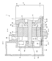
- FIG. 1 is a cross-sectional view showing a configuration example of an electric compressor according to the present invention.
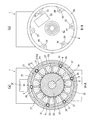
- 2A is a cross-sectional view taken along line AA of the electric compressor of FIG. 1
- FIG. 2B is an inverter housing housing viewed from line BB of the electric compressor of FIG. It is an end view of a member.
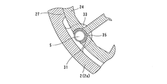
- FIG. 3 is a view showing a configuration in which a recess for inserting a fastening bolt is provided on the outer peripheral surface of the stator, and an elastic member is provided between the recess and the bolt.
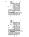
- FIG. 4A is a diagram showing a configuration in which the movement restricting portion is configured by a boss portion into which a fastening bolt is screwed, and the connector is protected by bringing the bobbin of the stator into contact with the boss portion first.
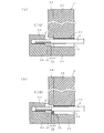
- FIG. 4B is a view showing a configuration in which an elastic member 36 is further interposed between the boss portion 33 and the bobbin 28 in FIG.
- FIG. 5A is a diagram illustrating a configuration in which the movement restricting portion is configured by a boss portion into which a fastening bolt is screwed, and a stator core that constitutes the stator is first brought into contact with the boss portion to protect the connector.
- FIG. 4A is a diagram showing a configuration in which the movement restricting portion is configured by a boss portion into which a fastening bolt is screwed, and the connector is protected by bringing the bobbin of the stator into contact with the boss portion first.
- FIG. 4B is a view showing a configuration in which an elastic member 36
- FIG. 5B is a diagram showing a configuration in which an elastic member 36 is further interposed between the boss portion 33 and the stator core 24 in FIG.
- the movement restricting portion is constituted by a step portion formed on the stator side from the boss portion to which the fastening bolt is screwed, and the stator core constituting the stator is first brought into contact with the step portion
- FIG. 6B is a diagram showing a configuration in which an elastic member 36 is further interposed between the stator core 24 and the stepped portion 37 in FIG. 6A.
- an electric compressor 1 suitable for a refrigeration cycle using a refrigerant as a working fluid is shown.
- a compression mechanism 3 is arranged on the right side in the figure in a housing 2 made of an aluminum alloy, and an electric motor 4 for driving the compression mechanism is arranged on the left side in the figure.
- the left side in the drawing is the front of the electric compressor, and the right side in the drawing is the rear of the electric compressor.
- the housing 2 is assembled to an electric motor housing member 2a (corresponding to a first housing member) that houses an electric motor 4 that drives the compression mechanism 3, and one axial end side (front end side) of the electric motor housing member 2a.
- An inverter housing member 2b (corresponding to a second housing member) for housing a substrate (not shown) on which a drive circuit in which the control circuit for driving the motor 4 and an inverter are integrated is mounted, and a shaft of the motor housing member 2a
- the motor housing housing member 2a and the inverter housing housing member 2b are fastened in the axial direction by the fastening bolts 5 and assembled to the other end side in the direction.
- the motor housing member 2a and the compression mechanism housing member 2c The bolt 6 is fastened in the axial direction.
- a partition wall 8 formed integrally with a shaft support portion 8a is provided on the side of the inverter housing member 2b that faces the motor housing housing member 2a, and is opposed to the compression mechanism housing member 2c of the motor housing housing member 2a.
- a partition wall 9 integrally formed with a shaft support portion 9a is provided on the side to be driven, and a drive shaft 10 is rotatably supported by the shaft support portions 8a and 9a of the partition walls 8 and 9 via bearings 11 and 12, respectively. ing. Due to the partition walls 8 and 9 formed in the electric motor housing member 2a and the inverter housing member 2b, the inside of the housing 2 is a compression mechanism housing space (not shown) for housing the compression mechanism 3 from the rear, and the electric motor.
- the inverter accommodating space 13b is formed by closing the open end of the inverter accommodating housing member 2b with a lid 14.
- the compression mechanism 3 is, for example, a known scroll type having a fixed scroll member and an orbiting scroll member disposed opposite thereto, a disc-shaped end plate fixed to a housing, and the end plate A cylindrical outer peripheral wall that is provided along the outer edge of the outer peripheral wall and is erected forward, and a spiral spiral that extends forward from the end plate inside the outer peripheral wall.
- a fixed scroll member having a wall, a disc-shaped end plate, and a spiral-shaped spiral wall standing rearward from the end plate, and a boss formed on the back surface of the end plate
- An orbiting scroll member connected to an eccentric shaft provided at the rear end portion of the drive shaft 10 and supported so as to be capable of revolving around the axis of the drive shaft 10, and these fixed scroll member and orbiting scroll member And it Engaging the spiral wall of les each other, in which defines a compression chamber in a space surrounded by the end plates and the spiral wall of the fixed scroll member and the end plate and the spiral wall of the orbiting scroll member.
- a refrigerant inlet for sucking a refrigerant introduced from a suction port 30 described later through the electric motor housing space 13a is formed.
- a discharge port for discharging the refrigerant gas compressed in the compression chamber is formed at substantially the center of the end plate of the fixed scroll member of the compression mechanism 3.
- the orbiting scroll member revolves around the axis of the drive shaft 10 and the compression chamber has a volume from the outer peripheral side to the center side of the spiral walls of both scroll members.
- the refrigerant gas is compressed by moving while gradually decreasing, and the compressed refrigerant gas is discharged from the discharge port formed in the end plate of the fixed scroll member.
- the stator 21 and the rotor 22 constituting the electric motor 4 are accommodated in the electric motor accommodating space 13a formed in the front part of the partition wall 9 in the housing 2.
- the stator 21 includes a cylindrical stator core 24 made of an iron-based material, a coil 25 (shown by a broken line in FIG. 2A) wound around a tooth of the stator core 24, and an axial end portion of the coil 25 (
- the insulator bobbin 28 (hereinafter referred to as a bobbin) attached to the coil end) is fixed to the inner peripheral surface of the housing 2 (motor housing member 2a).
- the drive shaft 10 is fixed with a rotor 22 in which a magnet is accommodated inside the stator 21.
- the rotor 22 is rotated by the rotating magnetic force formed by the stator 21 to rotate the drive shaft 10.
- a suction port 30 for sucking refrigerant gas is formed on the outer peripheral wall of the housing 2 (motor housing member 2a) facing the motor housing space 13a, and the refrigerant (compressed fluid) passes through the suction port 30 to drive the motor. It introduce
- the stator core 24 is fixed to the housing 2 (motor housing member 2a) by shrink fitting, and the axial position thereof is inserted into a step portion 26 formed in the housing 2 (motor housing member 2a).
- the compression mechanism housing housing member 2c side end) is abutted and fixed.
- the stator 21 is fixed to the housing 2 (motor housing member 2a) by extending along the axial direction of the drive shaft 10 on the inner circumferential surface of the housing 2 (motor housing member 2a) at different circumferential positions.
- a plurality of stator holding portions 27 are formed, and the plurality of stator holding portions 27 are shrink-fitted.
- the stator holding portion 27 is configured to bulge the inner peripheral wall of the housing 2 (electric motor housing member 2a) inward so as to contact the outer peripheral surface of the stator core 24 with a predetermined circumferential width.
- a plurality (for example, six) of motor housing housing members 2a) are formed at substantially equal intervals in the circumferential direction on the inner circumferential surface.
- the diameter of the inscribed circle of the plurality of stator holding portions 27 is formed to be slightly smaller than the outer diameter of the stator core 24 (the outer shape of the stator core 24 is slightly smaller than the diameter of the inscribed circle of the stator holding portion 27 of the housing 2).
- the housing 2 is heated to a high temperature and thermally expanded, and a normal temperature stator 21 is inserted into the stator core 24 until the insertion end of the stator core 24 contacts the stepped portion 26 of the housing 2. In other words, the stator 21 is contracted by being returned to, so that the stator 21 is tightly fixed to the stator holding portion 27.
- the stepped portion 26 formed on the inner wall of the housing 2 for positioning the axial direction of the stator core 24 may be formed continuously over substantially the entire circumference, or a plurality of stepped portions 26 may be provided in the circumferential direction. May be.
- the outer peripheral surface of the stator 21 that is not press-contacted by the stator holding portion 27 is a shaft through which the fastening bolt 5 is inserted by recessing the outer peripheral surface of the stator core 24.
- a recess 31 extending in the direction is formed.
- a plurality of recesses 31 are formed at equal intervals in the circumferential direction.
- the fastening bolts 5 inserted into the respective recesses 31 are inserted into the recesses 31 through the through holes 32 formed in the partition wall 9 from the side of the compression mechanism housing member 2c, and are inserted into the recesses 31 through the recesses 31. It is screwed into the screw hole 34 of the boss part 33 formed in the member 2b.
- An elastic member 35 is interposed in the gap between the inner peripheral surface of each recess 31 and the fastening bolt 5.
- the back portion of the inverter housing member 2b is thinned at a portion facing the stator 21, and the boss portion 33 is integrally formed on the inner peripheral wall thereof.
- a plurality of boss portions 33 are formed at equal intervals in the circumferential direction corresponding to the concave portion 31 (six locations in this example), and a surface facing the stator 21 is substantially perpendicular to the drive shaft 10.
- the boss portion 33 constitutes a movement restricting portion that restricts the movement of the stator 21 in the axial direction, and the positional relationship with the stator 21 is set as described later.
- electrical components such as a connector (cluster socket) 29 for electrically connecting the stator 21 and the inverter circuit board are disposed.
- the connector 29 is disposed at a position facing the bobbin 28 of the stator 21 in the axial direction.
- the bobbin 28 provided at the axial end portion of the stator 21 is provided so as to face the boss portion 33 in the axial direction, and the axial direction between the bobbin 28 and the connector 29 is provided.
- the distance A is set larger than the distance B in the axial direction between the bobbin 28 and the boss portion 33 (A> B).
- the boss portion 33 as the movement restricting portion, it is possible to prevent the connector 29 from coming into contact with the stator 21 and being damaged, and by using the boss portion 33 as the movement restricting portion, the existing housing can be prevented.
- the configuration can be used, and a new space is not required to provide the movement restricting portion, and an increase in the size of the compressor can be avoided.
- the fastening bolt 5 is inserted into the recess 31 formed on the outer peripheral surface of the stator, and the elastic member 35 is provided in the gap between the recess 31 and the fastening bolt 5, the holding force of the housing 2 with respect to the stator 21 is increased. Even in the case of a decrease, the circumferential movement of the stator 21 can be effectively suppressed.
- the bobbin 28 moves to the boss portion 33 in the axial direction of the stator 21 by making the interval between the bobbin 28 and the boss portion 33 narrower than the interval between the bobbin 28 and the connector 29.
- an elastic member 36 may be interposed between the boss portion 33 and the bobbin 28.
- the other end of the stator 21 (the end where the stator is inserted into the motor housing housing member 2a) is fixed in contact with the step portion 26, so that the holding force of the housing 2 on the stator 21 is reduced.
- the stator 21 moves only to the inverter housing member 2b side, and the movement restriction in the axial direction of the stator 21 is managed only by adjusting the dimension between the stator 21 and the boss portion 33. Therefore, the movement restriction management of the stator 21 can be easily performed.
- FIG. 5A shows another configuration example for managing the movement restriction of the stator 21 in the axial direction.
- the boss portion 33 is opposed to the stator core 24 in the axial direction of the stator 21, and the axial distance B between the boss portion 33 and the stator core 24 is greater than the axial distance A between the bobbin 28 and the connector 29. Also try to set it small. Since the other configuration examples are the same as the above configuration example, the same reference numerals are given to the same portions and the description thereof is omitted.
- stator 21 stator core 24
- stator 21 moving in the axial direction (in the direction of the inverter housing member 2b).
- stator core 24 comes into contact with the boss portion 33 before the bobbin 28 comes into contact with the connector 29, and it is possible to eliminate the possibility of the connector 29 being damaged.
- FIG. 6A shows still another configuration example for managing the movement restriction of the stator 21 in the axial direction.
- the stator core 24 and the stator core 24 are axially disposed on the inner peripheral wall of the inverter housing member 2 b on the stator side from the boss portion 33.
- the opposing stepped portion 37 is formed, and the axial distance D between the stator core 24 and the stepped portion 37 is set to be smaller than the axial distance C between the bobbin 28 and the boss portion 33. Therefore, in this example, the step part 37 is comprised as a movement control part. Since the other configuration examples are the same as the above configuration example, the same reference numerals are given to the same portions and the description thereof is omitted.
- the holding force with respect to the stator 21 (stator core 24) of the housing 2 decreases due to the difference in thermal expansion between the stator core 24 and the housing 2, and the stator 21 moves in the axial direction (in the direction of the inverter housing member 2b).
- the stator core 24 comes into contact with the stepped portion 37 before the bobbin 28 comes into contact with the boss portion 33, and it is possible to eliminate the possibility that the bobbin 28, which is an insulating member, is damaged.
- the above-described configurations may be used in appropriate combinations.
- the configuration shown in FIG. 6 is further provided so that the stator core 24 and the stepped portion 37 are brought into contact first.
- both the connector 29 and the bobbin 28 may be protected.
Landscapes
- Engineering & Computer Science (AREA)
- Mechanical Engineering (AREA)
- General Engineering & Computer Science (AREA)
- Compressor (AREA)
- Applications Or Details Of Rotary Compressors (AREA)
Description
本発明は、ハウジング内に、圧縮機構とこの圧縮機構を駆動する電動機とを備えた電動圧縮機に関し、特に、ハウジング内に収容された電動機のステータの移動を規制する機構を備えた電動圧縮機に関する。
電動圧縮機は、ハウジング内に、圧縮機構と、この圧縮機構を駆動する電動機とを収容して構成されるが、電動機を構成するステータをハウジングに固定する場合には、ハウジングの内径をステータコアの外径よりも僅かに小さく形成し、ハウジングを高温状態にすることで熱膨張させ、この熱膨張したハウジング内に常温のステータを嵌入させ、その後、ハウジングを常温に戻すことでハウジングを収縮させてステータをハウジングに固定する、いわゆる焼き嵌めが採用されている(特許文献1,2参照)。
しかしながら、ステータコアは、磁性材である鉄系材料が用いられ、これに対して、ハウジングは、軽量化のためにアルミ系材料が用いられており、熱膨張係数に大きな差がある。このため、ステータコアをハウジングに焼き嵌めによって固定する上述した構成においては、車両の運転状況によって電動圧縮機が高温になった場合に、ハウジングのステータコアに対する保持力が低下し、ステータコアがハウジングに対して移動し、コネクタ等の電装部品やボビン等の絶縁部材がステータやハウジングに接触し、破損する可能性があった。
本発明は、係る事情に鑑みてなされたものであり、高温時にハウジングのステータに対する保持力が低下した場合でも、ステータの移動を規制し、コネクタ等の電装部品やボビン等の絶縁部材の破損を防止することが可能な電動圧縮機を提供することを主たる課題としている。
上記課題を達成するために、本発明に係る電動圧縮機は、ハウジングと、このハウジング内に、圧縮機構と、この圧縮機構を駆動する電動機とを備え、前記電動機は、前記ハウジング内に固定されたステータと、駆動軸に固装されて前記ステータの内側に回転可能に配置されたロータとを具備する構成において、 前記ハウジングは、前記ステータが内部に固定される第1のハウジング部材と、前記第1のハウジング部材の軸方向の一端側に組み付けられる第2のハウジング部材とを少なくとも備え、前記第2のハウジング部材に前記ステータの軸方向の移動を規制する移動規制部が設けられていることを特徴としている。
したがって、高温時にハウジングのステータに対する保持力が低下し、ステータが軸方向に移動しようとした場合でも、第2のハウジング部材に設けられた移動規制部によりステータの軸方向の移動が規制され、コネクタ等の電装部品やボビン等の絶縁部材がステータやハウジングと接触することを回避することが可能となる。
特に、前記第2のハウジングと前記ステータとの間の空間に電装部品が配設される場合には、前記移動規制部と前記ステータとの軸方向の距離は、前記ステータと前記電装部品との軸方向の距離より短く設定することが好ましい。
このような構成とすることで、ハウジングのステータに対する保持力が低下してステータが軸方向に移動しても、ステータが電装部品に当たるよりも先に移動規制部材に当たるので、電装部品との接触を回避でき、電装部品を保護することが可能となる(電装部品の破損を回避することが可能となる)。
このような構成とすることで、ハウジングのステータに対する保持力が低下してステータが軸方向に移動しても、ステータが電装部品に当たるよりも先に移動規制部材に当たるので、電装部品との接触を回避でき、電装部品を保護することが可能となる(電装部品の破損を回避することが可能となる)。
ここで、上述した移動規制部は、前記第1のハウジング部材と前記第2のハウジング部材とを締結するボルトが螺合する前記第2のハウジング部材に形成されたボス部で構成するようにするとよい。
このような構成によれば、既存の構成を利用して移動規制部が構成されるので、移動規制部を設けるスペースが不要となる。
このような構成によれば、既存の構成を利用して移動規制部が構成されるので、移動規制部を設けるスペースが不要となる。
また、前記移動規制部と前記ステータとの間には、弾性部材を設けるようにしてもよい。
このような構成によれば、ハウジングのステータに対する保持力が低下しても、ステータの軸方向の移動や振動を弾性部材により効果的に抑えることが可能となる。
このような構成によれば、ハウジングのステータに対する保持力が低下しても、ステータの軸方向の移動や振動を弾性部材により効果的に抑えることが可能となる。
なお、ハウジングのステータに対する保持力が低下すると、軸方向のみならず、周方向にも移動することになるが、このような不都合は、前記ステータの外周面に、前記第1のハウジング部材と前記第2のハウジング部材とを締結するボルトを挿通させるための凹部を形成し、この凹部と前記ボルトとの間隙に、弾性部材を設けることで対応するとよい。
また、前記ステータの軸方向の端部であって、前記第2のハウジング部材とは反対側の端部は、前記第1のハウジング部材に設けられた段差部に当接するようにステータをハウジングに組み付けるとよい。
このような構成においては、ハウジングのステータに対する保持力が低下しても、ステータは、第2ハウジング側へしかずれることがないため、軸方向の片側(第2のハウジング部材側)だけの移動規制を管理すればいいことなり、ステータの移動規制管理が容易となる。
このような構成においては、ハウジングのステータに対する保持力が低下しても、ステータは、第2ハウジング側へしかずれることがないため、軸方向の片側(第2のハウジング部材側)だけの移動規制を管理すればいいことなり、ステータの移動規制管理が容易となる。
以上述べたように、本発明によれば、ステータが固定される第1のハウジング部材と軸方向で組み付けられる第2のハウジング部材に、ステータの軸方向の移動を規制する移動規制部を設けたので、ハウジングのステータに対する保持力が低下しても、ステータの軸方向の移動を規制することが可能となる。
このため、コネクタ等の電装部品やボビン等の絶縁部材がステータやハウジングと接触して破損することを防止することが可能となる。
このため、コネクタ等の電装部品やボビン等の絶縁部材がステータやハウジングと接触して破損することを防止することが可能となる。
また、移動規制部として、第1のハウジング部材と第2のハウジング部材とを締結するボルトが螺合するボス部を用いることで、既存のハウジング構成を利用することが可能となる。このため、移動規制部を設けるために新たなスペースが不要となり、圧縮機の大型化を避けることが可能となる。
さらに、移動規制部とステータとの間に弾性部材を配設することで、ステータの軸方向の移動や振動を効果的に抑えることが可能となる。
なお、ステータの外周面に第1のハウジング部材と第2のハウジング部材とを締結するボルトを挿通させる凹部を設け、この凹部とボルトとの間に弾性部材を設けることで、ステータの周方向の移動も規制できるので、ハウジングのステータに対する保持力が低下しても周方向に位置ずれして電装部品や絶縁部材を破損する不都合がなくなる。
また、ステータをハウジングに組み付けるにあたり、ステータの軸方向の端部であって、第2のハウジング部材とは反対側の端部を、第1のハウジング部材に設けられた段差部に当接させることで、ステータの軸方向の片側(第2のハウジング部材側)だけの移動規制を管理すればいいので、ステータの移動規制管理を容易に行うことが可能となる。
以下、本発明に係る電動圧縮機の構成例について、図面を参照しながら説明する。
図1及び図2において、冷媒を作動流体とする冷凍サイクルに適した電動圧縮機1が示されている。この電動圧縮機1は、アルミ合金で構成されたハウジング2内に、図中右方において圧縮機構3を配設し、また、図中左側において圧縮機構を駆動する電動機4を配設している。尚、図1において、図中左側を電動圧縮機の前方、図中右側を電動圧縮機の後方としている。
ハウジング2は、圧縮機構3を駆動する電動機4を収容する電動機収容ハウジング部材2a(第1のハウジング部材に相当)と、この電動機収容ハウジング部材2aの軸方向の一端側(前端側)に組み付けられ、電動機4を駆動制御する制御回路とインバータが一体となった駆動回路を搭載した図示しない基板を収容するインバータ収容ハウジング部材2b(第2のハウジング部材に相当)と、電動機収容ハウジング部材2aの軸方向の他端側に組み付けられ、圧縮機構3を収容する圧縮機構収容ハウジング部材2cとを有して構成され、電動機収容ハウジング部材2aとインバータ収容ハウジング部材2bとは締結ボルト5によって軸方向に締結され、また、電動機収容ハウジング部材2aと圧縮機構収容ハウジング部材2cとは、締結ボルト6によって軸方向に締結されている。
インバータ収容ハウジング部材2bの電動機収容ハウジング部材2aと対峙する側には、軸支部8aが一体に形成された仕切壁8が設けられ、また、電動機収容ハウジング部材2aの圧縮機構収容ハウジング部材2cと対峙する側には、軸支部9aが一体に形成された仕切壁9が設けられ、これら仕切壁8,9の軸支部8a,9aに駆動軸10がベアリング11,12を介して回転可能に支持されている。この電動機収容ハウジング部材2aとインバータ収容ハウジング部材2bとに形成された仕切壁8,9により、ハウジング2の内部が、後方から、圧縮機構3を収納する圧縮機構収容空間(図示せず)、電動機4を収納する電動機収容空間13a、及びインバータ回路基板を収容するインバータ収容空間13bに画成されている。
尚、この例では、インバータ収容空間13bは、インバータ収容ハウジング部材2bの開口端を蓋体14で閉塞することにより形成されている。
尚、この例では、インバータ収容空間13bは、インバータ収容ハウジング部材2bの開口端を蓋体14で閉塞することにより形成されている。
圧縮機構3は、例えば、固定スクロール部材とこれに対向配置された旋回スクロール部材とを有するそれ自体周知のスクロールタイプのものであり、ハウジングに固定された円板状の端板と、この端板の外縁に沿って全周に亘って設けられると共に前方に向かって立設された円筒状の外周壁と、その外周壁の内側において前記端板から前方に向かって延設された渦巻状の渦巻壁とを有する固定スクロール部材と、円板状の端板と、この端板から後方に向かって立設された渦巻状の渦巻壁とを有し、端板の背面に形成されたボス部に、駆動軸10の後端部に設けられた偏心軸が連結され、駆動軸10の軸心を中心として公転運動可能に支持されている旋回スクロール部材とを備え、これら固定スクロール部材と旋回スクロール部材とを、それぞれの渦巻壁を互いに噛み合わせ、固定スクロール部材の端板及び渦巻壁と旋回スクロール部材の端板及び渦巻壁とによって囲まれた空間で圧縮室を画成したものである。
固定スクロール部材の外周壁と旋回スクロール部材の渦巻壁の最外周部との間には、後述する吸入ポート30から導入された冷媒を電動機収容空間13aを介して吸入する冷媒流入口が形成され、また、圧縮機構3の固定スクロール部材の端板の略中央には、圧縮室で圧縮された冷媒ガスを吐出する吐出口が形成されている。
したがって、後述するロータ22が回転して駆動軸10が回転すると、旋回スクロール部材が駆動軸10の軸心の周りを公転し、圧縮室が両スクロール部材の渦巻壁の外周側から中心側へ容積を徐々に小さくしつつ移動して冷媒ガスを圧縮し、この圧縮された冷媒ガスを固定スクロール部材の端板に形成された吐出口から吐出するようにしている。
これに対して、ハウジング2内の仕切壁9より前方の部分に形成された電動機収容空間13aには、電動機4を構成するステータ21とロータ22とが収容されている。ステータ21は、鉄系素材で構成された円筒状をなすステータコア24とこのステータコア24のティースに巻回されたコイル25(図2(a)において破線で示す)とコイル25の軸方向端部(コイルエンド)に取り付けられたインシュレータボビン28(以下、ボビンと言う)で構成され、ハウジング2(電動機収容ハウジング部材2a)の内周面に固定されている。また、駆動軸10には、ステータ21の内側において、マグネットが収容されたロータ22が固装されている。このロータ22が、ステータ21によって形成される回転磁力により回転され、駆動軸10を回転するようになっている。
そして、電動機収容空間13aに臨むハウジング2(電動機収容ハウジング部材2a)の外周壁には、冷媒ガスを吸入する吸入ポート30が形成され、冷媒(被圧縮流体)をこの吸入ポート30を介して電動機収容空間13aに導入し、この電動機収容空間13aを通して前記圧縮機構3へ導くようにしている。
前記ステータコア24は、ハウジング2(電動機収容ハウジング部材2a)に焼嵌めによって固定されると共に、軸方向の位置がハウジング2(電動機収容ハウジング部材2a)に形成された段差部26に挿入端(ステータコア24の圧縮機構収容ハウジング部材2c側の端部)を当接させて位置決め固定されている。
ステータ21のハウジング2(電動機収容ハウジング部材2a)への固定は、ハウジング2(電動機収容ハウジング部材2a)の内周面に、周方向の異なる位置で駆動軸10の軸方向に沿って延設された複数のステータ保持部27を形成し、この複数のステータ保持部27に焼き嵌めによって行われる。
ステータ保持部27は、ハウジング2(電動機収容ハウジング部材2a)の内周壁を内側に膨出させてステータコア24の外周面に所定の周方向巾で当接させるようにしているもので、ハウジング2(電動機収容ハウジング部材2a)の内周面に周方向で略等間隔に複数(例えば、6つ)形成されている。このような複数のステータ保持部27の内接円の径をステータコア24の外径よりも僅かに小さく形成し(ステータコア24の外形をハウジング2のステータ保持部27の内接円の径よりも僅かに大きく形成し)、ハウジング2を高温状態にして熱膨張させ、そこに常温のステータ21をステータコア24の挿入端がハウジング2の段差部26に当接するまで挿入し、その状態でハウジング2を常温に戻すことで収縮させてステータ21をステータ保持部27に密着固定させるようにしている。
なお、前記ステータコア24の軸方向を位置決めするハウジング2の内壁に形成された段差部26は、ほぼ全周に亘って連続的に形成するようにしても、周方向に部分的に複数設けるようにしてもよい。
ステータ保持部27は、ハウジング2(電動機収容ハウジング部材2a)の内周壁を内側に膨出させてステータコア24の外周面に所定の周方向巾で当接させるようにしているもので、ハウジング2(電動機収容ハウジング部材2a)の内周面に周方向で略等間隔に複数(例えば、6つ)形成されている。このような複数のステータ保持部27の内接円の径をステータコア24の外径よりも僅かに小さく形成し(ステータコア24の外形をハウジング2のステータ保持部27の内接円の径よりも僅かに大きく形成し)、ハウジング2を高温状態にして熱膨張させ、そこに常温のステータ21をステータコア24の挿入端がハウジング2の段差部26に当接するまで挿入し、その状態でハウジング2を常温に戻すことで収縮させてステータ21をステータ保持部27に密着固定させるようにしている。
なお、前記ステータコア24の軸方向を位置決めするハウジング2の内壁に形成された段差部26は、ほぼ全周に亘って連続的に形成するようにしても、周方向に部分的に複数設けるようにしてもよい。
そして、ステータ21の外周面であって、ステータ保持部27で圧接されていない部分には、図3にも示されるように、ステータコア24の外周面を窪ませて前記締結ボルト5を挿通させる軸方向に延設された凹部31が形成されている。この凹部31は、図2(a)に示されるように、周方向に等間隔に複数(この例では6箇所)形成されている。
各凹部31に挿通される締結ボルト5は、圧縮機構収容ハウジング部材2cの側から仕切壁9に形成された通孔32を介して凹部31に挿入され、この凹部31を挿通してインバータ収容ハウジング部材2bに形成されたボス部33のネジ孔34に螺合させている。
また、各凹部31の内周面と締結ボルト5との間隙には、弾性部材35が介在されている。
また、各凹部31の内周面と締結ボルト5との間隙には、弾性部材35が介在されている。
インバータ収容ハウジング部材2bの背部は、図2(b)にも示されるように、ステータ21と対向する部分に肉抜きが施され、その内周壁に前記ボス部33が一体に形成されている。ボス部33は、前記凹部31に対応させて周方向に等間隔に複数(この例では6箇所)形成され、ステータ21と対峙する面を駆動軸10に対して略垂直としている。このボス部33は、ステータ21の軸方向の移動を規制する移動規制部を構成しており、ステータ21との位置関係は、後述のように設定されている。
また、ステータ21とインバータ収容ハウジング部材2bの仕切壁8との間の空間には、ステータ21とインバータ回路基板とを電気的に接続するコネクタ(クラスターソケット)29等の電装部品が配設され、この例においては、コネクタ29は、ステータ21のボビン28と軸方向で対向する位置に配設されている。
また、ステータ21とインバータ収容ハウジング部材2bの仕切壁8との間の空間には、ステータ21とインバータ回路基板とを電気的に接続するコネクタ(クラスターソケット)29等の電装部品が配設され、この例においては、コネクタ29は、ステータ21のボビン28と軸方向で対向する位置に配設されている。
図4(a)にも示されるように、ステータ21の軸方向端部に設けられたボビン28は、ボス部33と軸方向で対向するように設けられ、ボビン28とコネクタ29との軸方向の距離Aは、ボビン28とボス部33との軸方向の距離Bよりも大きく(A>B)設定されている。
したがって、電動圧縮機1が高温時において、ステータコア24とハウジング2との熱膨張差によりハウジング2のステータ21に対する保持力が低下し、軸方向(インバータ収容ハウジング部材2b方向)に移動する場合でも、ボビン28がコネクタ29に当接するよりも先にボビン28がボス部33に当接することとなり、コネクタ29が破損する恐れを無くすことが可能となる。
このように、ボス部33を移動規制部として用いることで、コネクタ29がステータ21と接触して破損することを防止でき、また、移動規制部として、ボス部33を用いることで、既存のハウジング構成を利用することが可能となり、移動規制部を設けるために新たなスペースが不要となり、圧縮機の大型化を避けることが可能となる。
また、ステータの外周面に形成された凹部31に締結ボルト5を挿通させ、この凹部31と締結ボルト5との間隙に、弾性部材35が設けられているので、ハウジング2のステータ21に対する保持力が低下した場合でも、ステータ21の周方向の移動をも効果的に抑えることが可能となる。
なお、上述の構成においては、ボビン28とボス部33との間の間隔をボビン28とコネクタ29との間隔よりも狭くすることで、ステータ21の軸方向の移動をボビン28がボス部33に当接するまでの範囲に規制するようにしたものであるが、図4(b)に示すように、ボス部33とボビン28との間に弾性部材36を介在させるようにしてもよく、このような構成とすることで、ハウジング2のステータ21に対する保持力が低下した場合でも、ステータ21の軸方向の移動や振動を効果的に抑えることが可能となる。
さらに、上述の例では、ステータ21の他端(ステータの電動機収容ハウジング部材2aへの挿入端)が段差部26に当接されて固定されているので、ハウジグ2のステータ21に対する保持力が低下した際には、ステータ21は、インバータ収容ハウジング部材2b側へしか移動することがなく、ステータ21とボス部33との間の寸法を調整するだけで、ステータ21の軸方向の移動規制を管理することが可能となるので、ステータ21の移動規制管理を容易に行うことが可能となる。
図5(a)に、ステータ21の軸方向の移動規制を管理する他の構成例が示されている。
この例においては、ステータ21の軸方向において、ボス部33ステータコア24に対峙させ、このボス部33とステータコア24との軸方向の間隔Bを、ボビン28とコネクタ29との軸方向の間隔Aよりも小さく設定するようにしている。
なお、他の構成例は前記構成例と同様であるので、同一箇所に同一符号を付して説明を省略する。
この例においては、ステータ21の軸方向において、ボス部33ステータコア24に対峙させ、このボス部33とステータコア24との軸方向の間隔Bを、ボビン28とコネクタ29との軸方向の間隔Aよりも小さく設定するようにしている。
なお、他の構成例は前記構成例と同様であるので、同一箇所に同一符号を付して説明を省略する。
このような例においても、ステータコア24とハウジング2との熱膨張差によりハウジング2のステータ21(ステータコア24)に対する保持力が低下し、ステータ21が軸方向(インバータ収容ハウジング部材2b方向)に移動する場合でも、ボビン28がコネクタ29に当接するよりも先にステータコア24がボス部33に当接することになり、コネクタ29が破損する恐れを無くすことが可能となる。
また、このような構成において、図5(b)に示されるように、ボス部33とステータコア24との間に弾性部材36を介在させることで、ハウジング2のステータ21に対する保持力が低下した場合でも、ステータ21の軸方向の移動や振動を効果的に抑えることが可能となる。また、他の作用効果についても、前記構成例と同様である。
図6(a)に、ステータ21の軸方向の移動規制を管理するさらに他の構成例が示されている。
この例においては、ステータ21の軸方向において、ボビン28の一部がボス部33と対峙する場合において、ボス部33よりステータ側となるインバータ収容ハウジング部材2bの内周壁に軸方向でステータコア24と対峙する段部37を形成し、ステータコア24と段部37との軸方向の距離Dをボビン28とボス部33との軸方向の距離Cより小さく設定するようにしている。したがって、この例では、段部37が移動規制部として構成されている。
なお、他の構成例は前記構成例と同様であるので、同一箇所に同一符号を付して説明を省略する。
この例においては、ステータ21の軸方向において、ボビン28の一部がボス部33と対峙する場合において、ボス部33よりステータ側となるインバータ収容ハウジング部材2bの内周壁に軸方向でステータコア24と対峙する段部37を形成し、ステータコア24と段部37との軸方向の距離Dをボビン28とボス部33との軸方向の距離Cより小さく設定するようにしている。したがって、この例では、段部37が移動規制部として構成されている。
なお、他の構成例は前記構成例と同様であるので、同一箇所に同一符号を付して説明を省略する。
このような例においては、ステータコア24とハウジング2との熱膨張差によりハウジング2のステータ21(ステータコア24)に対する保持力が低下し、ステータ21が軸方向(インバータ収容ハウジング部材2b方向)に移動する場合には、ボビン28がボス部33に当接するよりも先にステータコア24が段部37に当接することとなり、絶縁部材であるボビン28が破損する恐れを無くすことが可能となる。
このような構成においても、図6(b)に示されるように、ステータコア24と段部37との間に弾性部材36を介在させることで、ハウジング2のステータ21に対する保持力が低下した場合でも、ステータ21の軸方向の移動や振動を効果的に抑えることが可能となる。また、他の作用効果についても、前記構成例と同様である。
なお、上述した構成は、適宜組み合わせて用いるようにしてもよく、例えば、図4の構成において、図6に示される構成をさらに設け、ステータコア24と段部37とを最も先に当接させることで、コネクタ29とボビン28の両方を保護するようにしてもよい。
1 電動圧縮機
2 ハウジング
2a 電動機収容ハウジング部材
2b インバータ収容ハウジング部材
3 圧縮機構
4 電動機
5 締結ボルト
21 ステータ
22 ロータ
24 ステータコア
28 ボビン
29 コネクタ
33 ボス部
35,36 弾性部材
37 段部
2 ハウジング
2a 電動機収容ハウジング部材
2b インバータ収容ハウジング部材
3 圧縮機構
4 電動機
5 締結ボルト
21 ステータ
22 ロータ
24 ステータコア
28 ボビン
29 コネクタ
33 ボス部
35,36 弾性部材
37 段部
Claims (6)
- ハウジングと、このハウジング内に、圧縮機構と、この圧縮機構を駆動する電動機とを備え、前記電動機は、前記ハウジング内に固定されたステータと、駆動軸に固装されて前記ステータの内側に回転可能に配置されたロータとを具備する電動圧縮機において、
前記ハウジングは、前記ステータが内部に固定される第1のハウジング部材と、前記第1のハウジング部材の軸方向の一端側に組み付けられる第2のハウジング部材とを少なくとも備え、
前記第2のハウジング部材に前記ステータの軸方向の移動を規制する移動規制部が設けられていることを特徴とする電動圧縮機。 - 前記第2のハウジングと前記ステータとの間の空間には、電装部品が配設され、前記移動規制部と前記ステータとの軸方向の距離は、前記ステータと前記電装部品との軸方向の距離より短く設定されていることを特徴とする請求項1記載の電動圧縮機。
- 前記移動規制部は、前記第1のハウジング部材と前記第2のハウジング部材とを締結するボルトが螺合する前記第2のハウジング部材に形成されたボス部であることを特徴とする請求項1又は2記載の電動圧縮機。
- 前記移動規制部と前記ステータとの間には、弾性部材が設けられることを特徴とする請求項1乃至3のいずれかに記載の電動圧縮機。
- 前記ステータの外周面には、前記第1のハウジング部材と前記第2のハウジング部材とを締結するボルトを挿通させるための凹部が形成され、
前記凹部と前記ボルトとの間隙には、弾性部材が設けられていることを特徴とする請求項1乃至4のいずれかに記載の電動圧縮機。 - 前記ステータの軸方向の端部であって、前記第2のハウジング部材とは反対側の端部は、前記第1のハウジング部材に設けられた段差部に当接していることを特徴とする請求項1乃至5のいずれかに記載の電動圧縮機。
Priority Applications (1)
| Application Number | Priority Date | Filing Date | Title |
|---|---|---|---|
| CN201380040002.7A CN104508303B (zh) | 2012-08-24 | 2013-04-30 | 电动压缩机 |
Applications Claiming Priority (2)
| Application Number | Priority Date | Filing Date | Title |
|---|---|---|---|
| JP2012185620A JP5945194B2 (ja) | 2012-08-24 | 2012-08-24 | 電動圧縮機 |
| JP2012-185620 | 2012-08-24 |
Publications (1)
| Publication Number | Publication Date |
|---|---|
| WO2014030397A1 true WO2014030397A1 (ja) | 2014-02-27 |
Family
ID=50149715
Family Applications (1)
| Application Number | Title | Priority Date | Filing Date |
|---|---|---|---|
| PCT/JP2013/062534 Ceased WO2014030397A1 (ja) | 2012-08-24 | 2013-04-30 | 電動圧縮機 |
Country Status (3)
| Country | Link |
|---|---|
| JP (1) | JP5945194B2 (ja) |
| CN (1) | CN104508303B (ja) |
| WO (1) | WO2014030397A1 (ja) |
Families Citing this family (5)
| Publication number | Priority date | Publication date | Assignee | Title |
|---|---|---|---|---|
| WO2017209110A1 (ja) * | 2016-05-31 | 2017-12-07 | 株式会社ヴァレオジャパン | 電動圧縮機 |
| CN107659010A (zh) * | 2017-10-30 | 2018-02-02 | 南京磁谷科技有限公司 | 一种电机定子的压紧结构 |
| JP6450913B1 (ja) * | 2017-11-28 | 2019-01-16 | 株式会社石川エナジーリサーチ | スクロール圧縮機 |
| CN114396374A (zh) * | 2022-01-10 | 2022-04-26 | 上海海立新能源技术有限公司 | 一种应用挤压铝合金并带吸气流道的压缩机外壳 |
| JP2026031008A (ja) * | 2024-08-09 | 2026-02-24 | サンデン株式会社 | 電動圧縮機用モータ |
Citations (4)
| Publication number | Priority date | Publication date | Assignee | Title |
|---|---|---|---|---|
| JPS57118638U (ja) * | 1981-01-16 | 1982-07-23 | ||
| JP2002235669A (ja) * | 2001-02-08 | 2002-08-23 | Sanyo Electric Co Ltd | 密閉形圧縮機 |
| JP2008002420A (ja) * | 2006-06-26 | 2008-01-10 | Matsushita Electric Ind Co Ltd | 流体機械 |
| JP2009290995A (ja) * | 2008-05-29 | 2009-12-10 | Kayaba Ind Co Ltd | ブラシ付モータ |
Family Cites Families (8)
| Publication number | Priority date | Publication date | Assignee | Title |
|---|---|---|---|---|
| JP4045125B2 (ja) * | 2002-05-24 | 2008-02-13 | サンデン株式会社 | 電動圧縮機 |
| JP2006112276A (ja) * | 2004-10-13 | 2006-04-27 | Calsonic Compressor Inc | 電動気体圧縮機 |
| JP4644509B2 (ja) * | 2005-03-30 | 2011-03-02 | サンデン株式会社 | スクロール型流体機械 |
| JP4449811B2 (ja) * | 2005-04-15 | 2010-04-14 | 株式会社豊田自動織機 | 電動コンプレッサ |
| JP4857910B2 (ja) * | 2006-05-24 | 2012-01-18 | 株式会社豊田自動織機 | 電動モータ及び電動圧縮機 |
| US20110135523A1 (en) * | 2009-12-09 | 2011-06-09 | Williams John R | Sealed compressor with motor standard spacer providing bearing mount |
| JP2012120262A (ja) * | 2010-11-29 | 2012-06-21 | Aisin Seiki Co Ltd | 電動機のステータコアの取付構造 |
| CN102562519A (zh) * | 2010-12-24 | 2012-07-11 | 上海三电贝洱汽车空调有限公司 | 电动压缩机 |
-
2012
- 2012-08-24 JP JP2012185620A patent/JP5945194B2/ja active Active
-
2013
- 2013-04-30 CN CN201380040002.7A patent/CN104508303B/zh not_active Expired - Fee Related
- 2013-04-30 WO PCT/JP2013/062534 patent/WO2014030397A1/ja not_active Ceased
Patent Citations (4)
| Publication number | Priority date | Publication date | Assignee | Title |
|---|---|---|---|---|
| JPS57118638U (ja) * | 1981-01-16 | 1982-07-23 | ||
| JP2002235669A (ja) * | 2001-02-08 | 2002-08-23 | Sanyo Electric Co Ltd | 密閉形圧縮機 |
| JP2008002420A (ja) * | 2006-06-26 | 2008-01-10 | Matsushita Electric Ind Co Ltd | 流体機械 |
| JP2009290995A (ja) * | 2008-05-29 | 2009-12-10 | Kayaba Ind Co Ltd | ブラシ付モータ |
Also Published As
| Publication number | Publication date |
|---|---|
| JP2014043793A (ja) | 2014-03-13 |
| CN104508303B (zh) | 2017-03-29 |
| CN104508303A (zh) | 2015-04-08 |
| JP5945194B2 (ja) | 2016-07-05 |
Similar Documents
| Publication | Publication Date | Title |
|---|---|---|
| EP3093493B1 (en) | Electric scroll compressor | |
| CN104514718B (zh) | 涡旋式流体机械 | |
| JP6208534B2 (ja) | 電動スクロール圧縮機 | |
| JP5945194B2 (ja) | 電動圧縮機 | |
| CN107002676B (zh) | 电动涡旋压缩机 | |
| WO2013172189A1 (ja) | 電動圧縮機 | |
| WO2012098624A1 (ja) | 電動コンプレッサ | |
| WO2019044513A1 (ja) | 電動オイルポンプ | |
| CN106460818A (zh) | 电动压缩机 | |
| JP5594836B2 (ja) | 電動型圧縮機 | |
| US20250067261A1 (en) | Motor-driven compressor | |
| JP2017180425A (ja) | 電動コンプレッサ | |
| JPWO2016199884A1 (ja) | 電動圧縮機 | |
| WO2017209110A1 (ja) | 電動圧縮機 | |
| US20200227959A1 (en) | Motor and compressor having the same | |
| JP2016084768A (ja) | 電動圧縮機 | |
| JP5726102B2 (ja) | 電動圧縮機 | |
| JP2013096283A (ja) | 電動オイルポンプ装置 | |
| JP2008309017A (ja) | ファンモータ | |
| JP2003343438A (ja) | 電動圧縮機 | |
| JP6074203B2 (ja) | スクロール型圧縮機 | |
| JP2011241799A (ja) | 電動圧縮機の中継接続構造 | |
| JP5931488B2 (ja) | 電動圧縮機 | |
| JPWO2019117227A1 (ja) | 電動圧縮機の基板保持構造 | |
| JP6036405B2 (ja) | 電動圧縮機 |
Legal Events
| Date | Code | Title | Description |
|---|---|---|---|
| 121 | Ep: the epo has been informed by wipo that ep was designated in this application |
Ref document number: 13831253 Country of ref document: EP Kind code of ref document: A1 |
|
| NENP | Non-entry into the national phase |
Ref country code: DE |
|
| 122 | Ep: pct application non-entry in european phase |
Ref document number: 13831253 Country of ref document: EP Kind code of ref document: A1 |