WO2014024660A1 - フッ素ガス生成装置及びフッ素ガス生成装置の制御方法 - Google Patents
フッ素ガス生成装置及びフッ素ガス生成装置の制御方法 Download PDFInfo
- Publication number
- WO2014024660A1 WO2014024660A1 PCT/JP2013/069596 JP2013069596W WO2014024660A1 WO 2014024660 A1 WO2014024660 A1 WO 2014024660A1 JP 2013069596 W JP2013069596 W JP 2013069596W WO 2014024660 A1 WO2014024660 A1 WO 2014024660A1
- Authority
- WO
- WIPO (PCT)
- Prior art keywords
- fluorine gas
- electrolytic
- gas
- fluorine
- electrolytic cell
- Prior art date
- Legal status (The legal status is an assumption and is not a legal conclusion. Google has not performed a legal analysis and makes no representation as to the accuracy of the status listed.)
- Ceased
Links
Images

Classifications
-
- C—CHEMISTRY; METALLURGY
- C01—INORGANIC CHEMISTRY
- C01B—NON-METALLIC ELEMENTS; COMPOUNDS THEREOF; METALLOIDS OR COMPOUNDS THEREOF NOT COVERED BY SUBCLASS C01C
- C01B7/00—Halogens; Halogen acids
- C01B7/19—Fluorine; Hydrogen fluoride
- C01B7/20—Fluorine
-
- C—CHEMISTRY; METALLURGY
- C25—ELECTROLYTIC OR ELECTROPHORETIC PROCESSES; APPARATUS THEREFOR
- C25B—ELECTROLYTIC OR ELECTROPHORETIC PROCESSES FOR THE PRODUCTION OF COMPOUNDS OR NON-METALS; APPARATUS THEREFOR
- C25B1/00—Electrolytic production of inorganic compounds or non-metals
- C25B1/01—Products
- C25B1/24—Halogens or compounds thereof
- C25B1/245—Fluorine; Compounds thereof
-
- C—CHEMISTRY; METALLURGY
- C25—ELECTROLYTIC OR ELECTROPHORETIC PROCESSES; APPARATUS THEREFOR
- C25B—ELECTROLYTIC OR ELECTROPHORETIC PROCESSES FOR THE PRODUCTION OF COMPOUNDS OR NON-METALS; APPARATUS THEREFOR
- C25B15/00—Operating or servicing cells
- C25B15/02—Process control or regulation
Definitions
- the present invention relates to a fluorine gas generation device and a control method for the fluorine gas generation device.
- Patent Document 1 includes an electrolytic bath for electrolyzing hydrogen fluoride in an electrolytic bath made of a molten salt containing hydrogen fluoride, and generates a product gas containing fluorine gas as a main component in the first gas phase portion on the anode side.
- a fluorine gas generation device that generates a by-product gas mainly containing hydrogen gas in a second gas phase portion on the cathode side is disclosed.
- the product gas is stored in the main buffer tank, and the pressure in the main buffer tank is measured with a pressure gauge.
- the measurement result of the pressure gauge is transmitted to the control unit, and the control unit performs on / off control of the current source based on the measurement result of the pressure gauge.
- the amount of product gas generated at the anode is controlled based on the pressure in the main buffer tank.
- Patent Document 2 discloses a method for controlling current to an electrolytic cell necessary for electrolysis.
- the current control method described in Patent Document 2 measures the voltage fluctuation width between the cathode and the anode when a constant current is applied to the electrolytic cell, and changes the input current amount according to the voltage fluctuation width. It is a method of applying.
- the power supply method to the electrolytic cell necessary for the electrolysis of the fluorine gas generator is generally the current value output from the power supply device as described in Patent Document 1 and Patent Document 2. And the power is controlled so that the voltage value fluctuates according to the course. This is because the relationship of the following (Equation 1) is established between the flow rate of fluorine gas generated from the electrolytic cell by electrolysis and the current value energized in the electrolytic cell, and by controlling the current value, This is because the flow rate of fluorine gas generated from the electrolytic cell can be controlled.
- the voltage applied in energizing the electrolytic cell is a theoretical electrolysis voltage (about 2.9 V) calculated from the standard electrode potential of fluorine and hydrogen generated by electrolysis.
- it is a value obtained by adding the voltage generated due to the activation overvoltage and the electrical resistance of the members constituting the electrolytic cell.
- the activation overvoltage is a voltage resulting from energy required for activation of the electrolytic reaction, and varies depending on the type of electrode and the composition of the electrolytic bath.
- the resistance is the total of the resistance of the member that is energized among the members included in the electrolytic cell, the contact resistance of each member, and the wiring that connects the electrolytic cell and the power supply device. Since these resistance values are determined by the configuration of the electrolytic cell and the material used, the same value can be obtained if the electrolytic cell has the same structure.
- anode effect occurs in which no current flows even when a voltage is applied.
- the fluorine gas generated by electrolysis is very corrosive, so the members inside the electrolytic cell may be corroded.
- the electrolytic bath is a molten salt containing hydrogen fluoride
- the members inside the electrolytic cell may be corroded by hydrogen fluoride. Since the electrical resistance increases due to the progress of the corrosion, the voltage applied to allow the same current to flow increases. When the voltage increases, the load (current ⁇ voltage) applied to the electrolytic cell (electrode pair) increases, so that electric corrosion tends to occur, and Joule heat (current ⁇ voltage ⁇ time) increases.
- an increase in Joule heat leads to an increase in temperature in the electrolytic cell, further increasing the reactivity between the surface of the anode and fluorine gas, thereby further promoting the corrosion of the anode.
- fluorine gas is generated using a plurality of electrolytic cells, the progress of corrosion or the frequency of occurrence of the anode effect differs depending on the electrolytic cell.
- corrosion of the member is further promoted, and problems such as an increase in maintenance frequency of the electrolytic cell occur.
- the present invention has been made in view of the above problems, and in a fluorine gas generation apparatus that generates fluorine gas using a plurality of electrolytic cells, the use of the electrolytic cell generated by the difference in electrode resistance between the electrolytic cells.
- An object of the present invention is to provide a fluorine gas generation device capable of automatically supplying fluorine gas stably while reducing shortening of life.
- One aspect of the present invention is a fluorine gas generation device that generates fluorine gas by electrolyzing a fluorine compound in an electrolytic bath, each of which includes a container and a fluorine compound contained in the container.
- An electrolytic cell a power source for supplying electric power necessary for generating fluorine gas by electrolysis to the plurality of electrolytic cells, and an actual current detection for detecting a current supplied from the power source to the plurality of electrolytic cells And a total sum of currents applied to the plurality of electrolytic cells based on the amount of gas containing fluorine gas generated by the plurality of electrolytic cells, and the plurality of currents detected by the actual current detector.
- the power supply is set at the output voltage so that the value of the voltage applied to the plurality of electrolytic cells increases or decreases in the same direction.
- a controller for controlling.
- Fluorine gas when controlling the power to a plurality of electrolytic cells in the fluorine gas generator, while reducing the shortening of the service life of the electrolytic cell caused by the difference in electrical resistance between the electrolytic cells, Fluorine gas can be supplied automatically and stably.
- the fluorine gas generation device of this embodiment generates fluorine gas using a plurality of electrolytic cells. Each electrolytic cell generates fluorine gas by electrolysis in an electrolytic bath containing a fluorine compound.
- the fluorine gas generation device of the present embodiment determines the total current value to be supplied to the plurality of electrolytic cells in the control of the amount of fluorine gas generated in the plurality of electrolytic cells, and according to the determined total current value, The voltage supplied to each electrolytic cell is adjusted.
- the fluorine gas generation device of the present embodiment is a fluorine gas generation device including a plurality of electrolytic cells that generate fluorine gas, without significantly increasing only the load applied to some of the electrolytic cells in the plurality of electrolytic cells. Gas is supplied automatically and stably.
- the fluorine gas generation device of the present embodiment has a plurality of electrolytic cells (electrolytic cell units).
- electrolytic cell units electrolytic cell units
- the electrolytic cell unit 50 of the present embodiment includes an electrolytic cell 1 that generates fluorine gas by electrolysis, devices and valves for controlling the electrolytic cell 1, and a path for deriving the gas generated in the electrolytic cell 1 ( Including valve).
- the electrolytic cell unit 50 is controlled by the controller 10.
- the controller 10 controls the operation of each device and each valve based on the detection result (monitoring result) output from each meter.
- the controller 10 controls each electrolytic cell unit 50 and other devices and valves.
- FIG. 1 illustrates a plurality of rectangles indicated by reference numeral “10” for convenience of explanation, and these all indicate the same controller 10.
- the controller 10 can include separate components (control devices) assigned to each electrolytic cell 1 unit.
- the controller 10 can include different components (control devices) that control different equipment and valves.
- the controller 10 includes, for example, a CPU that is a processor, a ROM that is a nonvolatile storage device that stores a program and control data used by the program, and a microcomputer that includes a RAM that is a main storage device. Programs and data stored in the ROM are loaded into the RAM.
- the CPU realizes a predetermined function implemented in the controller 10 by executing a program stored in the RAM.
- the RAM stores a program executed by the processor and control data necessary for executing the program.
- the hardware configuration of the controller 10 is not limited. For example, part or all of the functions of the controller 10 may be realized by a logic circuit.
- the molten salt containing hydrogen fluoride (HF) is stored in the container of the electrolytic cell 1.
- a mixture (KF ⁇ 2HF) of hydrogen fluoride and potassium fluoride (KF) is used as the molten salt.
- KF ⁇ 2HF hydrogen fluoride
- KF potassium fluoride
- the inside of the electrolytic cell 1 is partitioned into an anode chamber 11 and a cathode chamber 12 by a partition wall 6 that is partially immersed in the molten salt and partially exposed on the molten salt.
- Each of the anode chamber 11 and the cathode chamber 12 includes a portion filled in the molten salt and an air chamber on the surface of the molten salt liquid.
- the electrolytic cell 1 has an anode 7 and a cathode 8, and the anode 7 and the cathode 8 are immersed in the molten salts of the anode chamber 11 and the cathode chamber 12, respectively.
- a main raw gas mainly composed of fluorine gas (F 2 ) is generated at the anode 7.
- By-product gas mainly containing hydrogen gas (H 2 ) is generated.
- a carbon electrode for example, a carbon electrode is used, and for the cathode 8, for example, soft iron, monel, or nickel is used.
- the materials of the anode 7 and the cathode 8 are not limited to these, and appropriate materials are selected depending on the design.
- the air chamber 121 is partitioned by the partition wall 6 so that the mutual gas cannot come and go.
- the first air chamber 111 and the second air chamber 121 are completely separated by the partition wall 6 in order to prevent a reaction due to the contact of fluorine gas and hydrogen gas.
- the molten salt in the anode chamber 11 and the cathode chamber 12 is not separated by the partition wall 6, and the anode chamber 11 and the cathode chamber 12 communicate with each other in the molten salt through the lower portion of the partition wall 6.
- the main gas outlet passage 60 for leading the main gas generated at the anode 7 is connected to the first air chamber 111.
- the second gas chamber 121 is connected to a by-product gas outlet path 70 for extracting the by-product gas generated at the cathode 8.
- each of the fluorine gas and the hydrogen gas generated from the anode 7 and the cathode 8 of the electrolytic cell 1 hydrogen fluoride is vaporized from the molten salt by the vapor pressure and mixed.
- each of the main product gas generated at the anode 7 and guided to the first air chamber 111 and the by-product gas generated at the cathode 8 and guided to the second air chamber 121 contains hydrogen fluoride gas. It is.
- the electrolytic cell unit 50 includes a temperature adjusting device 65 that adjusts the temperature of the molten salt in the electrolytic cell 1.
- the temperature of the molten salt in the electrolytic cell 1 is adjusted by the temperature adjusting device 65 to 71.7 ° C. or higher, for example, 85 to 95 ° C., which is the melting point of KF ⁇ 2HF.
- the electrolytic cell unit 50 is installed in the electrolytic cell 1 and includes a thermometer 69 as a temperature detector that detects the temperature of the molten salt. The detection result of the thermometer 69 is output to the controller 10.
- the temperature adjusting device 65 includes a jacket 66 set on the outer wall of the electrolytic cell 1, a tube (not shown) set inside the electrolytic cell 1, and is installed outside the electrolytic cell 1.
- a heating / cooling device 67 for circulating steam or cooling water through the tube is provided.
- the controller 10 controls the temperature adjustment device 65 according to the temperature detected by the thermometer 69.
- the temperature adjustment device 65 adjusts the temperature of the molten salt. Specifically, the temperature adjusting device 65 circulates steam from the heating / cooling device 67 to the jacket 66 and the tube when raising the temperature of the molten salt, and lowers the temperature of the molten salt when heating the cooling salt 67. Then, cooling water is circulated through the jacket 66 and the tube.
- the configuration and presence of the temperature control device 65 of the electrolytic cell 1 depend on the design. For example, only one of the jacket 66 and the tube may be installed. Further, instead of circulating steam or cooling water through the jacket 66 and the tube, a hot refrigerant such as silicone oil may be circulated. Furthermore, you may make it adjust the temperature of molten salt by providing heat exchangers, such as a heater and a capacitor
- heat exchangers such as a heater and a capacitor
- the electrolytic cell 1 is provided with a liquid level gauge 14 as a liquid level detector for detecting the liquid level of the stored molten salt.
- the liquid level gauge 14 detects the back pressure when the nitrogen gas at a constant flow rate is purged into the molten salt through the insertion tube 141 inserted in the electrolytic cell 1, and the liquid level gauge 14 detects the liquid pressure from the back pressure and the liquid specific gravity of the molten salt. It is a back pressure type liquid level gauge that detects the surface level.
- the detection result of the liquid level gauge 14 is output to the controller 10.
- the electrolytic cell unit 50 includes a differential pressure gauge 20 as a differential pressure detector that detects a pressure difference between the first air chamber 111 and the second air chamber 121 of the electrolytic cell 1. The detection result of the differential pressure gauge 20 is output to the controller 10.
- the electrolytic cell unit 50 includes a raw material supply system 5 that supplies hydrogen fluoride, which is a raw material of fluorine gas, into the molten salt of the electrolytic cell 1.
- a raw material supply system 5 that supplies hydrogen fluoride, which is a raw material of fluorine gas, into the molten salt of the electrolytic cell 1.
- the raw material supply system 5 is demonstrated.
- the raw material supply system 5 is installed outside the electrolytic cell 1 with the raw material supply passage 41 connected to the electrolytic cell 1, connected to the electrolytic cell 1 through the raw material supply channel 41, and supplemented to the electrolytic cell 1.
- a hydrogen fluoride supply source 40 in which hydrogen fluoride is stored. Hydrogen fluoride stored in the hydrogen fluoride supply source 40 is supplied into the molten salt of the electrolytic cell 1 through the raw material supply passage 41.
- the raw material supply passage 41 is provided with a flow rate control valve 42 for controlling the supply flow rate of hydrogen fluoride.
- the controller 10 controls the flow control valve 42 (the opening thereof), and the flow control valve 42 adjusts the opening based on a signal output from the controller 10. Specifically, the controller 10 controls the supply flow rate of hydrogen fluoride so that the liquid level of the molten salt detected by the level gauge 14 is stored in the ROM and becomes a predetermined level set in advance. That is, the flow rate control valve 42 controls the supply flow rate of hydrogen fluoride so as to replenish hydrogen fluoride electrolyzed in the molten salt.
- a carrier gas supply passage 46 that guides a carrier gas supplied from a carrier gas supply source 45 installed outside the electrolytic cell unit 50 into the raw material supply passage 41 is connected to the raw material supply passage 41.
- the carrier gas supply passage 46 is provided with a cutoff valve 47 for switching between supply and cutoff of the carrier gas.
- the carrier gas is a gas for introducing hydrogen fluoride into the molten salt, and for example, nitrogen gas that is an inert gas is used.
- nitrogen gas is supplied into the molten salt in the cathode chamber 12.
- the nitrogen gas is hardly dissolved in the molten salt and is discharged from the second air chamber 121 through the byproduct gas processing system.
- another inert gas such as argon gas or helium gas may be used as the carrier gas.
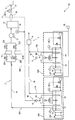
- the fluorine gas generation device 100 includes a plurality of electrolytic cell units, and supplies the fluorine gas generated thereby to the external device 4.
- the external device 4 is, for example, a semiconductor manufacturing device.
- the fluorine gas is used as a cleaning gas in a semiconductor manufacturing process, for example.
- the fluorine gas generation device 100 includes at least two (two or more) electrolytic cell units.
- two electrolytic cell units 50A and 50B are shown.
- the electrolytic cell unit 50A has an electrolytic cell 1A, an anode 7A, and a cathode 8A
- the electrolytic cell unit 50B has an electrolytic cell 1B, an anode 7B, and a cathode 8B.
- the main raw gas generated in the anode 7A is led out by the main raw gas outlet passage 60A, and the main raw gas generated in the anode 7B is led out by the main raw gas outlet passage 60B.
- the electrolytic cell units 50A and 50B have the same configuration.
- the electrolytic cell units 50A and 50B may have different configurations, for example, different anode and cathode electrolysis areas, or may have other different elements.
- the electrolytic area is the area of the surface of the electrode that is immersed in the molten salt and that faces the counter electrode (a cathode in the case of an anode, and an anode in the case of a cathode).
- the cardinal number of the electrolytic cell unit 50 included in the fluorine gas generation device 100 is selected according to the main raw gas generation capability of the electrolytic cell 1 included in the electrolytic cell unit 50 and the fluorine gas supply flow rate required for the fluorine gas generation device 100, and in particular.
- the upper limit is not limited.
- the fluorine gas generator 100 further includes a power supply system 80 that supplies electric power necessary for electrolysis to the electrolytic cell 1, a fluorine gas supply system 2 that supplies the fluorine gas generated from the electrolytic cell unit 50 to the external device 4, And the byproduct gas processing system
- the controller 10 controls operations of devices, instruments, valves, and the like included in the fluorine gas generation device 100.
- the fluorine gas supply system 2 includes a first main passage 15, a purifier 16, a booster 17, a buffer tank 21, a flow meter 26, and a flow control valve 27.
- the first main passage 15 is a passage for collecting the fluorine gas from the electrolytic cell units 50 ⁇ / b> A and 50 ⁇ / b> B and supplying it to the external device 4.
- the main raw gas outlet passages 60 ⁇ / b> A and 60 ⁇ / b> B of the electrolytic cell units 50 ⁇ / b> A and 50 ⁇ / b> B are connected to the first main passage 15 and concentrated in the first main passage 15.
- the first main passage 15 is provided with a buffer tank 21 for storing fluorine gas.
- the gas stored in the buffer tank 21, in this example, the fluorine gas, is supplied to the external device 4.
- the buffer tank 21 is provided with a pressure gauge 24 as a pressure detector for detecting the internal pressure. The detection result of the pressure gauge 24 is output to the controller 10.
- a flow meter 26 is provided downstream of the buffer tank 21 in the first main passage 15 as a flow rate detector for detecting the flow rate of the gas supplied from the buffer tank 21 to the external device 4, in this example, fluorine gas. ing.
- the detection result of the flow meter 26 is output to the controller 10.
- the pressure gauge 24 and the flow meter detect the amount of gas generated by the electrolytic cells 1A and 1B (the amount of fluorine gas in the example of FIG. 2).
- the adjustment method of the electric power supplied to the electrolytic cells 1A and 1B according to the detection results of the pressure gauge 24 and the flow meter 26 will be described in detail later.
- a flow rate control valve 27 for adjusting the flow rate of the fluorine gas supplied to the external device 4 is provided downstream of the flow meter 26 in the first main passage 15.
- the opening degree of the flow control valve 27 is controlled in accordance with a signal output from the controller 10.
- the controller 10 controls the opening degree of the flow control valve 27 based on the flow rate of fluorine gas detected by the flow meter 26 and a predetermined reference flow rate value. For example, the controller 10 controls the opening degree of the flow rate control valve 27 so that the flow rate of the fluorine gas detected by the flow meter 26 matches the reference flow rate value (target flow rate value).
- the target flow rate value may be calculated from a value stored in advance in the ROM or stored in the ROM.
- a plurality of target flow values are stored in the ROM of the controller 10.
- the target flow rate is determined according to the flow rate of the fluorine gas required by the external device 4, and, for example, they match.
- the target flow rate value referred in the control of the flow rate control valve 27 is changed by an operator who operates the fluorine gas generation device 100.
- the controller 10 may control the flow control valve 27 (gas flow rate) by other methods.
- the controller 10 may control the flow rate control valve 27 so that the gas flow rate falls within a numerical range determined by the reference value.
- a booster 17 that boosts the fluorine gas is provided upstream of the buffer tank 21 in the first main passage 15.
- a positive displacement pump such as a bellows pump or a diaphragm pump is used for the booster 17.
- the booster 17 need not be installed.
- the purification device 16 includes two systems of a first purification device 161A and a second purification device 161B provided in parallel, and upstream of the first purification device 161A and the second purification device 161B, respectively.
- Inlet valves 22A and 22B are provided, and outlet valves 23A and 23B are provided downstream, respectively.
- the opening and closing of the inlet valves 22A and 22B and the outlet valves 23A and 23B are switched so that the fluorine gas generated from the anodes 7A and 7B passes through only one of the first purification device 161A and the second purification device 161B. That is, when one of the first refining device 161A and the second refining device 161B is in an operating state, the other is stopped or in a standby state.
- the purification device 16 may be configured by one or three or more systems.
- the byproduct gas processing system 3 includes a second main passage 30 and an abatement part 34.
- the by-product gas outlet paths 70A and 70B that are connected to the second air chambers of the electrolyzers 1A and 1B and lead out the by-product gas are aggregated and connected to the second main passage 30.
- the second main passage 30 is provided with an abatement part 34, and the by-produced hydrogen gas is rendered harmless by the abatement part 34 and released.
- reference numeral 80 indicates two locations, but these indicate components included in the power supply system 80.
- a power supply device 9A for supplying electric power necessary for electrolysis is connected to the anode 7A and the cathode 8A installed in the electrolytic cell 1A included in the electrolytic cell unit 50A.
- a power supply device 9B that supplies electric power necessary for electrolysis is connected to the anode 7B and the cathode 8B installed in the electrolytic cell 1B included in the electrolytic cell unit 50B.
- the power supply devices 9A and 9B are included in the power supply system 80.
- a controller 10 is connected to the power supply devices 9A and 9B. As will be described later, the controller 10 controls the power supply devices 9A and 9B with the output voltages from the power supply devices 9A and 9B, and the power supply devices 9A and 9B directly control the output voltage, so that the power supply devices 9A and 9B have the electrolytic cells 1A and 1B (electrodes). The power (current) supplied to the pair) is controlled.
- the controller 10 uses the power supply device 9A to adjust the voltage applied between the electrodes of the anode 7A and the cathode 8A, while collecting the data of the actually energized voltage value and current value from the power supply device 9A. Similarly, the controller 10 adjusts the voltage applied between the electrodes of the anode 7B and the cathode 8B by the power supply device 9B, while collecting the data of the actually energized voltage value and current value from the power supply device 9B. .
- a plurality of power supply devices 9A and 9B are connected to one controller 10, and one controller 10 controls the plurality of power supply devices 9A and 9B.
- an individual controller may be connected to each of the power supply apparatuses 9A and 9B.
- all controllers are connected by an interface such as Ethernet or RS-232C, and data necessary for controlling the power supply apparatus is shared by all controllers.
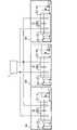
- FIG. 3 schematically shows another configuration example of the fluorine gas generation device 100, which is different from FIG.
- one power supply device 9A or 9B is connected to each of the electrolytic cell units 50A and 50B.
- power may be supplied from one power supply device 9 to the plurality of electrolytic cells.
- three electrolytic cell units 50A to 50C are connected in parallel to one power supply device 9 connected to the controller 10.
- the controller 10 controls the outputs from the power supply devices 9A and 9B in voltage.
- the fluorine gas generation device of the present embodiment determines a total current value to be supplied to the plurality of electrolytic cells, and supplies each electrolytic cell based on the determined total current value. Adjust the output voltage.
- the fluorine gas generation device of the present embodiment can stably supply fluorine gas.
- the controller 10 increases or decreases the voltage supplied to the plurality of electrolytic cells in the same direction based on the determined total current value. Thereby, it can prevent more appropriately that corrosion advances greatly only in the specific electrolytic cell in a plurality of electrolytic cells.
- the controller 10 adjusts the voltage output to each of the plurality of electrolytic cells so that the ratio of the voltage values output to the plurality of electrolytic cells is constant.
- the voltage value output from the power supply device 9A to the electrolytic cell 1A is V1
- the voltage output from the power supply device 9B to the electrolytic cell 1B is V2
- the controller 10 has a constant ratio of V1 and V2.
- the power supply devices 9A and 9B are controlled as shown.
- the ratio between V1 and V2 may be determined in accordance with, for example, the ratio of the electrolytic areas of the anodes 7A and 7B between the electrolytic cells 1A and 1B (for example, they match). In the control of three or more electrolytic cells, the ratio between different electrolytic cell pairs is the same or different.
- the controller 10 may control the power supply device so that the amount of increase or decrease in the voltage value output to the plurality of electrolytic cells is the same.
- the same or different reference voltage values are defined for the plurality of electrolytic cells, and the controller 10 changes the voltage output to the plurality of electrolytic cells by the same amount from the reference voltage value, and outputs the voltage between the electrolytic cells.
- the difference in voltage output voltage is constant. When the difference is 0, the output voltage values to the two electrolytic cells are the same. In the control of three or more electrolytic cells, the difference between different electrolytic cell pairs is the same or different.
- the fluorine gas can be generated without greatly increasing only the load applied to some electrolytic cells without requiring a complicated control configuration. It can be supplied automatically and stably.
- outputs from one power supply device 9 to all the electrolytic cell units 50A to 50C are parallel, and all output voltages are the same.
- the voltage value ratio between the electrolytic cells is 1 or the difference is 0.
- the controller 10 outputs a control signal to each power supply device so that the voltage value output from the power supply device to the electrode pair of the electrolytic cell is the same in all electrolytic cells.
- the supply of fluorine gas from the fluorine gas generator 100 is not stopped. Only the electrolytic cell unit corresponding to the cancellation may be stopped. In this case, the same voltage is applied only to the electrode pair of an electrolytic cell (electrolytic cell used for generating fluorine gas) other than the electrolytic cell unit corresponding to the suspension of use.
- the controller 10 uses data (pressure and flow rate) detected by a pressure gauge 24 that monitors the pressure of the buffer tank 21 and a flow meter 26 that monitors the flow rate downstream of the buffer tank 21 in the first main passage 15. Based on the calculated current value and the operator input value (parameter), a current value required for electrolysis (total current value for a plurality of electrolytic cells) is calculated, and the calculated value and each electrolytic cell 1A, 1B are calculated. The voltage output from the power supply devices 9A and 9B is controlled by comparison with the sum of the current values actually energized.
- the controller 10 detects the flow rate of the fluorine gas supplied from the fluorine gas generation device 100 to the external device 4 by the flow meter 26, and generates the fluorine gas that maintains the detected flow rate from the detection result according to the above equation 1.
- a current value (target current value) necessary for electrolysis for performing the calculation is calculated.
- the ROM of the controller 10 stores the following formula 2 obtained by modifying the formula 1 with the current efficiency in the formula 1 set to 95%.
- the controller 10 calculates a target current value in accordance with the formula 2.
- the minimum current value is set for the target current value.
- the minimum current value is set based on a preset minimum current density value.
- the current density is obtained by dividing the current value by the electrolytic area of the anode 7 installed in the electrolytic cell 1.
- the minimum current density is set When a 0.5A / dm 2, when the electrolytic area of the anode is 10 dm 2, the minimum current value is 5A. Accordingly, the power supply devices 9A and 9B are controlled so that the target current value does not become 0A even when the flow rate detected by the flow meter 26 is 0 L / min. However, when the flow rate detected by the flow meter 26 continues 0 L / min for a certain time or more, the power supply devices 9A and 9B are controlled so that the target current value becomes 0A.
- the controller 10 detects the pressure in the buffer tank 21 with the pressure gauge 24, and calculates a correction current value from the target current value or other preset current value based on the detection result.
- a plurality of pressure ranges are defined in advance for the detected pressure in the pressure gauge 24.
- the pressure is divided into six pressure ranges (sections), and sections 1 to 6 are defined in descending order of pressure.
- the pressure range of section 1 is the highest and the pressure range of section 6 is the lowest.
- the range of the pressure range is determined by the capacity and pressure resistance of the buffer tank 21 and the capacity of the booster pump included in the booster 17.
- a correction current value calculation method is defined for each section.
- An example of the calculation method of the correction current value in each section is as follows.
- Category 1: Correction current value Electrolysis stop (0A)
- Category 2: Correction current value Minimum current value
- Category 3: Correction current value Target current value x 90%
- Category 4: Correction current value Target current value
- Category 5: Correction current value Target current value ⁇ 110%
- Category 6: Correction current value Maximum current value of the fluorine gas generator 100
- the controller 10 compares the detection result of the pressure gauge 24 with each section, and specifies the section including the detection result.
- the controller 10 calculates the correction current value according to the calculation method associated with the identified category.
- the “maximum current value of the fluorine gas generation device 100” in the calculation method defined for the category 6 is determined by the specifications of each device such as the electrolytic cells 1A and 1B and the power supply devices 9A and 9B included in the fluorine generation device 100. This is the upper limit of the current value calculated by multiplying the design capability of the fluorine generator 100 by a certain safety factor.
- the safety factor is determined based on the design guidelines of the fluorine gas generation device 100. In addition, if there is an electrolytic cell whose use is suspended due to circumstances such as the above-mentioned maintenance or emergency, according to the situation, The timely safety factor is changed. For example, when a fluorine gas generation device including three electrolytic cells is designed with a safety factor of 75%, the maximum current value when the three electrolytic cells are operating is the design capacity of the fluorine gas generation device x 75%. When one of the three electrolytic cells needs to be stopped due to maintenance, the safety factor is changed to 2/3 of 75%, that is, 50%, and the maximum current value is a fluorine gas generator. The design ability is calculated as 50%.
- the upper limit value of the target flow rate of fluorine gas that can be changed by the operator who operates the fluorine gas generation device 100 is also changed according to the maximum current value. Specifically, a flow rate calculated by inputting the maximum current value of the fluorine gas generation device 100 to the current value of Equation 2 described above is captured (stored) in the controller 10 as the upper limit value of the target flow rate, and this calculation is performed. When the flow rate value input by the operator is larger than the upper limit value of the target flow rate, the controller 10 automatically changes the flow rate value input by the operator to the upper limit value of the target flow rate.
- the controller 10 calculates the actual current value and the current deviation range in parallel with the calculation of the correction current value. Specifically, the controller 10 takes in the data of the current values energized from each of the power supply devices 9A and 9B included in the fluorine gas generation device 100 from the power supply devices 9A and 9B, and sums them. (Total current value) is stored in the RAM as an actual current value. For example, the controller 10 calculates 2% of the maximum current value of the fluorine gas generation device 100 as the current deviation range, and stores the value in the ROM.
- the controller 10 compares the calculated correction current value with the actual current value.
- the controller 10 starts to decrease the voltage value output from each power supply device 9A, 9B to each electrolytic cell 1A, 1B.
- the decreasing speed of the voltage value varies depending on the configuration of the electrolytic cells 1A and 1B and the capacity of the entire fluorine gas generation apparatus 100.
- the controller 10 calculates an appropriate speed in advance and reduces the voltage at that speed.
- Controller 10 compares the corrected current value and the actual current value at all times or at regular intervals, and adjusts the adjustment of the voltage value.
- the length of the cycle depends on the specification of the fluorine gas generation device 100 itself and the usage environment. For example, the period is set to less than 10 minutes.
- the pressure fluctuation of the buffer tank 21 occurs due to the difference between the flow rate of the fluorine gas supplied to the external device 4 and the flow rate of the fluorine gas generated in the electrolytic cells 1A and 1B. It may be difficult to keep the pressure within an appropriate range.
- the controller 10 may adjust the output voltages of the power supply devices 9A and 9B by other methods. For example, the controller 10 calculates the resistance value of each electrolytic cell from the current value and the voltage value before the voltage change is started, and the actual current value (the sum of the current values of the electrolytic cells 1A and 1B) is calculated using the calculated value. An estimated voltage value that matches the corrected current value is calculated. After the change to the voltage value, the controller 10 confirms the actual current value, and adjusts the output voltage value by the above method according to the difference between the actual current value and the correction current value.
- the current value supplied between the anode and the cathode from the power supply device is calculated based on the flow rate of fluorine gas supplied from the buffer tank to the external device, and the calculated current value By correcting based on the pressure in the buffer tank, fluorine gas can be supplied to an external device more stably.
- the purification device 16 is installed in the first main passage 15, but for the purpose of reducing the size of the purification device, the same number of purification devices as the electrolytic cell units are prepared, and the main gas derived from each electrolytic cell is derived. Each may be installed on the route. If the purity of the fluorine gas in the generated main gas is not an industrial problem, it is not necessary to install a purifier.
- the corrected current value is determined based on the amount of gas generated by a plurality of electrolytic cells (the amount of fluorine gas after purification in the above example) with reference to the detection values of the flow meter and the pressure gauge.
- the present invention can be applied to a fluorine gas generator that does not have a buffer tank.
- the controller monitors the flow rate of fluorine gas (one value representing the amount of gas generated by a plurality of electrolytic cells) supplied to the external device, and outputs the flow rate to each electrolytic cell so that the flow rate approaches the reference value. Adjust the voltage.
- the controller does not use the pressure detection value in the main passage, adjusts the voltage output to each electrolytic cell using the detected gas flow value, and does not refer to the fluorine gas flow rate, and detects in the buffer tank.
Landscapes
- Chemical & Material Sciences (AREA)
- Organic Chemistry (AREA)
- Engineering & Computer Science (AREA)
- Chemical Kinetics & Catalysis (AREA)
- Electrochemistry (AREA)
- Materials Engineering (AREA)
- Metallurgy (AREA)
- Inorganic Chemistry (AREA)
- Automation & Control Theory (AREA)
- Electrolytic Production Of Non-Metals, Compounds, Apparatuses Therefor (AREA)
Description
本発明は、フッ素ガス生成装置及びフッ素ガス生成装置の制御方法に関する。
従来のフッ素ガスの生成装置として、電気分解によってフッ素ガスを生成する装置が知られている。特許文献1には、フッ化水素を含む溶融塩からなる電解浴中でフッ化水素を電解する電解槽を備え、陽極側の第1気相部分にフッ素ガスを主成分とするプロダクトガスを発生させると共に、陰極側の第2気相部分に水素ガスを主成分とする副生ガスを発生させるフッ素ガス生成装置が開示されている。
特許文献1に記載のフッ素ガス生成装置では、プロダクトガスは主バッファタンクに貯留され、主バッファタンク内の圧力は圧力計にて測定される。圧力計の測定結果は制御部に伝達され、制御部は圧力計の測定結果に基づいて電流源をオンオフ制御する。このように、陽極にて発生するプロダクトガスの発生量は、主バッファタンク内の圧力に基づいて制御される。
また、特許文献2には、電気分解に必要な電解槽への電流の制御方法が開示されている。特許文献2に記載の電流制御方法は、電解槽に一定の電流を印加したときの陰極、陽極間の電圧変動幅を測定し、この電圧変動幅に応じて投入電流量を変動させながら電流を印加する方法である。
このように、フッ素ガス生成装置の電気分解に必要な電解槽への電力供給方法は、一般的に、特許文献1や特許文献2に記載されている様に、電源装置から出力される電流値を調整し、電圧値は成り行きで変動する様に、電力を制御する。これは、電気分解によって電解槽から発生するフッ素ガスの流量と、電解槽に通電した電流値との間には下記(数式1)式の関係が成り立っており、電流値を制御することにより、電解槽から発生するフッ素ガスの流量が制御できるためである。

一方、電解槽への通電において印加される電圧、すなわち、電気分解に必要な電圧は、電気分解によって発生するフッ素と水素の標準電極電位等から算出される理論電解電圧(約2.9V)に、活性化過電圧及び電解槽を構成する部材の電気抵抗に起因して発生する電圧を加えた値となる。活性化過電圧は、電解反応の活性化に必要なエネルギーに起因する電圧であり、電極の種類や電解浴の組成によって変化する。また、部材の電気抵抗に起因して発生する電圧は、オームの法則により、電圧=電流値×抵抗の関係に依存する。
ここで、抵抗は、電解槽に含まれる部材のうち電気が通電される部材の電気抵抗や、各部材の接触抵抗の他、電解槽と電源装置を繋ぐ配線などの抵抗の総和である。これらの抵抗値は、電解槽の構成や使用する材質によって決まるため、同じ構造の電解槽であれば同様の値が得られる。
しかし、フッ素ガスを発生させる電解槽内では、電解浴中の陽極の表面が発生したフッ素ガスと反応することにより、陽極の濡れ性が低下し、電気抵抗が増大する場合がある。この濡れ性の低下が極端に進行すると、電圧を印加しても電流が流れなくなる、いわゆる「陽極効果」と呼ばれる現象が発生する。
また、電気分解によって発生したフッ素ガスは腐食性が非常に高いため、電解槽内部の部材が腐食される可能性がある。さらに、電解浴がフッ化水素を含む溶融塩である場合には、フッ化水素により電解槽内部の部材が腐食される可能性もある。この腐食の進行により電気抵抗が増加するため、同一値の電流を流すために印加する電圧は増加することになる。電圧が増加すると、電解槽(電極対)にかかる負荷(電流×電圧)が増大するため、電気腐食が発生しやすくなり、ジュール熱(電流×電圧×時間)が増大する。
特に、ジュール熱の増大は、電解槽内の温度上昇を招き、陽極の表面とフッ素ガスとの反応性がさらに高まり、これにより陽極の腐食がさらに促進する。複数の電解槽を用いてフッ素ガスを生成する場合、腐食の進行又は電解槽ごとに陽極効果の発生頻度は異なる。抵抗が増大した電解槽では部材の腐食がより促進され、その電解槽のメンテナンス頻度が増大する等の問題を生じる。
本発明は、上記の問題点に鑑みてなされたものであり、複数の電解槽を用いてフッ素ガスを生成するフッ素ガス生成装置において、電解槽間での電極抵抗の差によって生じる電解槽の使用寿命の短縮化を低減しつつ、安定してフッ素ガスを自動供給することができるフッ素ガス生成装置を提供することを目的とする。
本発明の一態様は、電解浴中のフッ素化合物を電気分解することによって、フッ素ガスを生成するフッ素ガス生成装置であって、それぞれが、容器と、前記容器内に収容されているフッ素化合物を含む電解浴と、前記電解浴に挿入された陽極及び陰極と、を有し、前記陽極及び陰極間を流れる電流により前記電解浴中のフッ素化合物を電気分解することによりフッ素ガスを生成する、複数の電解槽と、前記複数の電解槽に、電気分解によるフッ素ガスの生成に必要な電力を供給する電源と、前記電源から前記複数の電解槽へ与えられている電流を検出する、実電流検出器と、前記複数の電解槽によるフッ素ガスを含むガスの生成量に基づいて前記複数の電解槽に与える電流の総和を決定し、前記実電流検出器により検出された前記複数の電解槽へ与えられている電流の総和と前記決定した電流の総和との比較結果に応じて、前記複数の電解槽へ与えられる電圧の値が同一方向において増減するように、前記電源を出力電圧において制御する、コントローラと、を含むものである。
本発明の一態様によれば、フッ素ガス生成装置において複数の電解槽への電力を制御する場合、電解槽間での電気抵抗の差によって生じる電解槽の使用寿命の短縮化を低減しつつ、安定してフッ素ガスを自動供給することができる。
以下、添付図面を参照して本発明の実施形態を説明する。本実施形態は本発明を実現するための一例に過ぎず、本発明の技術的範囲を限定するものではない。本実施形態のフッ素ガス生成装置は、複数の電解槽を用いてフッ素ガスを生成する。各電解槽は、フッ素化合物を含む電解浴において、電気分解によりフッ素ガスを生成する。
本実施形態のフッ素ガス生成装置は、複数の電解槽におけるフッ素ガス生成量の制御において、当該複数の電解槽へ供給する総電流値を決定し、決定した総電流値に応じて、当該複数の電解槽のそれぞれに供給する電圧を調整する。本実施形態のフッ素ガス生成装置は、フッ素ガスを生成する複数の電解槽を含むフッ素ガス生成装置において、当該複数の電解槽における一部の電解槽にかかる負荷のみを大きく増大させることなく、フッ素ガスを安定して自動供給する。
上述のように、本実施形態のフッ素ガス生成装置は、複数の電解槽(電解槽ユニット)を有する。まず、図1を参照して、本実施形態のフッ素ガス生成装置が使用する電解槽ユニット50の構成を説明する。
本実施形態の電解槽ユニット50は、電気分解によってフッ素ガスを生成する電解槽1と、電解槽1を制御するための機器及び弁並びに電解槽1において生成されたガスを導出するための経路(弁を含む)を含む。電解槽ユニット50は、コントローラ10によって制御される。
コントローラ10は、各計器から出力される検出結果(監視結果)に基づいて各機器及び各弁の動作を制御する。以下に説明する例においては、コントローラ10は、各電解槽ユニット50及び他の機器や弁を制御する。図1は、説明の便宜上、参照符号「10」で指示された複数の矩形を図示するが、これらは全て同一のコントローラ10を示している。コントローラ10は、各電解槽1ユニットに割り当てられた、分離された構成要素(制御デバイス)を含むことができる。コントローラ10は、異なる機器や弁を制御する異なる構成要素(制御デバイス)を含むことができる。
コントローラ10は、例えば、プロセッサであるCPU、プログラム及び当該プログラムが使用する制御データを格納する不揮発性記憶デバイスであるROM、及び、主記憶デバイスであるRAMを備えるマイコン、を有する。ROMに記憶されているプログラム及びデータは、RAMにロードされる。
CPUは、RAMに記憶されているプログラムを実行することによってコントローラ10に実装される所定の機能を実現する。RAMは、プロセッサによって実行されるプログラム、及び、プログラムの実行に必要な制御データを記憶する。本実施形態においてコントローラ10のハードウェア構成は限定されず、例えば、コントローラ10の機能の一部又は全ては論理回路により実現されていてもよい。
本例において、電解槽1の容器には、フッ化水素(HF)を含む溶融塩が貯留される。本実施の形態では、溶融塩として、フッ化水素とフッ化カリウム(KF)の混合物(KF・2HF)が用いられる。これは一例であって、電気分解によりフッ素ガスを生成するためのフッ素化合物及びそれを含む電解液は、フッ素ガス生成装置の設計に従って適切な材料が選択される。
電解槽1の内部は、溶融塩中にその一部が浸漬され、一部が溶融塩上で露出している区画壁6によって、陽極室11と陰極室12とに区画される。陽極室11及び陰極室12は、それぞれ、溶融塩中で満たされている部分と、溶融塩液面上の気室とを含む。
電解槽1は陽極7及び陰極8を有し、陽極室11及び陰極室12の溶融塩中には、それぞれ陽極7及び陰極8が浸漬される。陽極7と陰極8との間に電源装置9から電気分解に必要な電力が供給されることによって、陽極7ではフッ素ガス(F2)を主成分とする主生ガスが生成され、陰極8では水素ガス(H2)を主成分とする副生ガスが生成される。陽極7には、例えば、炭素電極が用いられ、陰極8には、例えば、軟鉄、モネル、又はニッケルが用いられる。陽極7及び陰極8の材料は、これらに限定されず、設計により適切な材料が選択される。
本例において、電解槽1内の溶融塩液面上には、陽極7にて生成されたフッ素ガスが導かれる第1気室111と、陰極8にて生成された水素ガスが導かれる第2気室121とが、互いのガスが行き来不能に区画壁6によって区画される。このように、第1気室111と第2気室121とは、フッ素ガスと水素ガスとの混触による反応を防ぐため、区画壁6によって完全に分離される。これに対して、陽極室11と陰極室12の溶融塩は、区画壁6によって分離されず、陽極室11と陰極室12は、区画壁6の下方を通じて、溶融塩内で連通している。
第1気室111には、陽極7で発生した主生ガスを導出するための主生ガス導出通路60が接続している。第2気室121には、陰極8で発生した副生ガスを導出するための副生ガス導出経路70が接続している。
電解槽1の陽極7及び陰極8から生成されたフッ素ガス及び水素ガスのそれぞれには、溶融塩からフッ化水素が蒸気圧分だけ気化して混入する。このように、陽極7にて生成され第1気室111に導かれる主生ガス及び陰極8にて生成され第2気室121に導かれる副生ガスのそれぞれには、フッ化水素ガスが含まれている。
電解槽ユニット50は、電解槽1内の溶融塩の温度を調節する温度調節装置65を含む。電解槽1内の溶融塩の温度は、温度調節装置65によってKF・2HFの融点である71.7℃以上、例えば、85~95℃に調節される。電解槽ユニット50は、電解槽1に設置され、溶融塩の温度を検出する温度検出器としての温度計69を含む。温度計69の検出結果は、コントローラ10に出力される。
本例において、温度調節装置65は、電解槽1の外壁に設定されたジャケット66、電解槽1の内部に設定されたチューブ(図示せず)、電解槽1の外部に設置され、ジャケット66及びチューブに蒸気又は冷却水を循環させる加熱冷却装置67を備える。コントローラ10は、温度計69の検出温度に応じて温度調節装置65を制御する。
コントローラ10から出力される信号に従って、温度調節装置65は、溶融塩の温度調節を行う。具体的には、温度調節装置65は、溶融塩の温度を上げる場合には、加熱冷却装置67からジャケット66及びチューブに蒸気を流通させ、溶融塩の温度を下げる場合には、加熱冷却装置67からジャケット66及びチューブに冷却水を流通させる。
電解槽1の温度調節装置65の構成及び有無は、設計に依存する。例えば、ジャケット66及びチューブのいずれか一方のみを設置してもよい。また、ジャケット66及びチューブに蒸気又は冷却水を循環させる代わりに、シリコンオイル等の温冷媒を循環させるようにしてもよい。さらに、電解槽1の外壁にヒータやコンデンサ等の熱交換機を設けて溶融塩の温度を調節するようにしてもよい。
電解槽1には、貯留された溶融塩の液面レベルを検出する液面レベル検出器としての液面計14が設けられる。液面計14は、電解槽1内に挿入された挿入管141を通じて一定流量の窒素ガスを溶融塩中にパージした際の背圧を検知し、その背圧と溶融塩の液比重とから液面レベルを検出する背圧式液面計である。液面計14の検出結果はコントローラ10に出力される。
また、電解槽ユニット50は、電解槽1の第1気室111と第2気室121との圧力差を検出する差圧検出器としての差圧計20を含む。差圧計20の検出結果は、コントローラ10に出力される。
電解槽ユニット50は、電解槽1の溶融塩中にフッ素ガスの原料であるフッ化水素を供給する原料供給系統5を含む。以下では、原料供給系統5について説明する。本例において、原料供給系統5は、電解槽1と接続する原料供給通路41と、電解槽1の外部に設置され、原料供給通路41を介して電解槽1に接続し、電解槽1に補充するためのフッ化水素が貯留されたフッ化水素供給源40とを含む。フッ化水素供給源40に貯留されたフッ化水素は、原料供給通路41を通じて電解槽1の溶融塩中に供給される。
原料供給通路41には、フッ化水素の供給流量を制御する流量制御弁42が設けられている。コントローラ10は流量制御弁42(の開度)を制御し、流量制御弁42は、コントローラ10から出力される信号に基づいて開度を調整する。具体的には、コントローラ10は、液面計14によって検出された溶融塩の液面レベルがROMに記憶され予め定められた所定レベルとなるように、フッ化水素の供給流量を制御する。つまり、流量制御弁42は、溶融塩中で電気分解されたフッ化水素を補給するように、フッ化水素の供給流量を制御する。
また、原料供給通路41には、電解槽ユニット50の外部に設置されたキャリアガス供給源45から供給されるキャリアガスを原料供給通路41内に導くキャリアガス供給通路46が接続される。キャリアガス供給通路46には、キャリアガスの供給と遮断を切り換える遮断弁47が設けられている。キャリアガスは、フッ化水素を溶融塩中に導くためのガスであり、例えば、不活性ガスである窒素ガスが用いられる。
本例において、窒素ガスは、陰極室12の溶融塩中に供給される。窒素ガスは、溶融塩中にほとんど溶けず、第2気室121から副生ガス処理系統を通じて排出される。なお、キャリアガスとして、他の不活性ガス、例えばアルゴンガスやヘリウムガスを用いるようにしてもよい。
次に、図2を参照して、本発明の実施の形態に係るフッ素ガス生成装置100について説明する。フッ素ガス生成装置100は、複数の電解槽ユニットを含み、それらによって生成されたフッ素ガスを、外部装置4へと供給する。外部装置4は、例えば半導体製造装置である。その場合、フッ素ガスは、例えば、半導体の製造工程においてクリーニングガスとして使用される。
フッ素ガス生成装置100は、少なくとも2基(2基以上)の電解槽ユニットを含み、図2の例においては、2基の電解槽ユニット50A、50Bが示されている。電解槽ユニット50Aは電解槽1A並びに陽極7A及び陰極8Aを有し、電解槽ユニット50Bは電解槽1B並びに陽極7B及び陰極8Bを有する。
陽極7Aにおいて生成された主生ガスは主生ガス導出通路60Aにより導出され、陽極7Bにおいて生成された主生ガスは主生ガス導出通路60Bにより導出される。本例において、電解槽ユニット50A、50Bは同一構成を有する。電解槽ユニット50A、50Bは異なる構成、例えば、異なる陽極と陰極の電解面積を有していてもよいし、他の異なる要素を有していてもよい。電解面積は、電極において溶融塩に浸漬された部分で、対極(陽極の場合は陰極、陰極の場合は陽極)と向かい合った面の面積である。
フッ素ガス生成装置100に含まれる電解槽ユニット50の基数は、電解槽ユニット50に含まれる電解槽1の主生ガス発生能力とフッ素ガス生成装置100に必要なフッ素ガス供給流量によって選択され、特に上限は制限されない。
フッ素ガス生成装置100は、さらに、電気分解に必要な電力を電解槽1に供給する電力供給系統80、電解槽ユニット50から生成したフッ素ガスを外部装置4へと供給するフッ素ガス供給系統2、そして、フッ素ガスの生成に伴って生成された副生ガスを処理する副生ガス処理系統3を備える。コントローラ10は、フッ素ガス生成装置100に含まれる機器や計器類、バルブ等の動作を制御する。
先ず、フッ素ガス供給系統2について説明する。フッ素ガス供給系統2は、第1メイン通路15、精製装置16、昇圧装置17、バッファタンク21、流量計26、流量制御弁27を含む。第1メイン通路15は、電解槽ユニット50A、50Bからのフッ素ガスを集約し、外部装置4へ供給するための通路である。電解槽ユニット50A、50Bの主生ガス導出通路60A、60Bは第1メイン通路15に接続し、第1メイン通路15に集約されている。
第1メイン通路15に、フッ素ガスを貯留するためのバッファタンク21が設けられている。バッファタンク21に貯留されたガス、本例においてフッ素ガスは、外部装置4へと供給される。バッファタンク21には、その内部圧力を検出する圧力検出器としての圧力計24が設けられている。圧力計24の検出結果はコントローラ10に出力される。
第1メイン通路15におけるバッファタンク21の下流には、バッファタンク21から外部装置4へと供給されるガス、本例においてフッ素ガス、の流量を検出する流量検出器としての流量計26が設けられている。流量計26の検出結果はコントローラ10に出力される。圧力計24と流量計とは、電解槽1A、1Bが生成したガスの量(図2の例でフッ素ガスの量)を検出する。なお、圧力計24及び流量計26の検出結果に応じた電解槽1A、1Bへ供給する電力の調整方法については後で詳述する。
第1メイン通路15における流量計26の下流には、外部装置4へと供給されるフッ素ガスの流量を調整する流量制御弁27が設けられる。流量制御弁27はコントローラ10から出力される信号に応じて開度が制御される。
具体的には、コントローラ10は、流量計26によって検出されたフッ素ガスの流量と所定の基準流量値とに基づいて、流量制御弁27の開度を制御する。例えば、コントローラ10は、流量計26によって検出されたフッ素ガスの流量が、上記基準流量値(目標流量値)と一致するように、流量制御弁27の開度を制御する。目標流量値は、ROMに予め記憶されている又はROMに記憶された値から算出してもよい。
例えば、コントローラ10のROMには複数の目標流量値が記憶されている。目標流量は、外部装置4が必要とするフッ素ガスの流量に応じて決まり、例えば、それらは一致する。流量制御弁27の制御において参照される目標流量値は、フッ素ガス生成装置100を操作するオペレータによって変更される。コントローラ10は、他の方法により流量制御弁27(ガス流量)を制御してもよい。例えば、コントローラ10は、基準値で決まる数値範囲内にガス流量が入るように、流量制御弁27を制御してもよい。
第1メイン通路15におけるバッファタンク21の上流には、フッ素ガスを昇圧する昇圧装置17が設けられる。例えば、昇圧装置17には、ベローズポンプやダイアフラムポンプ等の容積型ポンプが用いられる。昇圧装置17を設置しなくともよい。
第1メイン通路15における昇圧装置17の上流には、フッ素ガスに混入したフッ化水素ガスを捕集してフッ素ガスを精製する精製装置16が設けられる。図2の例において、精製装置16は、並列に設けられた第1精製装置161Aと第2精製装置161Bの2つの系統からなり、第1精製装置161A及び第2精製装置161Bの上流にはそれぞれ入口弁22A、22Bが設けられ、下流にはそれぞれ出口弁23A、23Bが設けられている。
入口弁22A、22B及び出口弁23A、23Bは、陽極7A、7Bから生成されたフッ素ガスが第1精製装置161A及び第2精製装置161Bのいずれか一方のみを通過するように開閉が切り換えられる。つまり、第1精製装置161A及び第2精製装置161Bのうち一方が運転状態である場合には、他方は停止又は待機状態となる。精製装置16は、1又は3以上の系統で構成されていてもよい。
次に、副生ガス処理系統3について説明する。副生ガス処理系統3は、第2メイン通路30及び除害部34を含む。各電解槽1A、1Bの第2気室に接続され、副生ガスを導出するための副生ガス導出経路70A、70Bは集約され、第2メイン通路30に接続される。第2メイン通路30には、除害部34が設けられ、副生された水素ガスは、除害部34にて無害化されて放出される。
次に電力供給系統80について説明する。図2では、符号80が、2か所を示しているが、これらは、電力供給系統80に含まれる構成要素を指示している。電解槽ユニット50Aに含まれる電解槽1Aに設置された陽極7Aと陰極8Aには、電気分解に必要な電力を供給する電源装置9Aが接続される。同様に、電解槽ユニット50Bに含まれる電解槽1Bに設置された陽極7Bと陰極8Bには、電気分解に必要な電力を供給する電源装置9Bが接続される。電源装置9A、9Bは、電力供給系統80に含まれている。
電源装置9A、9Bにはコントローラ10が接続されている。後述するように、コントローラ10は、電源装置9A、9Bからの出力電圧において電源装置9A、9Bを制御し、出力電圧を直接に制御することで電源装置9A、9Bが電解槽1A、1B(電極対)に供給する電力(電流)を制御する。
コントローラ10は、電源装置9Aにより、陽極7Aと陰極8Aの電極間に印加する電圧を調整する一方で、実際に通電された電圧値と電流値のデータを、電源装置9Aから収集する。同様に、コントローラ10は、電源装置9Bにより、陽極7Bと陰極8Bの電極間に印加する電圧を調整する一方で、実際に通電された電圧値と電流値のデータを、電源装置9Bから収集する。
本例においては、1台のコントローラ10に対して複数台の電源装置9A、9Bが接続しており、1台のコントローラ10が複数台の電源装置9A、9Bを制御している。これと異なり、電源装置9A、9Bのそれぞれに、個別のコントローラを接続してもよい。この構成においては、全てのコントローラがイーサネットやRS-232Cなどのインターフェイスで接続され、電源装置の制御に必要なデータが、全てのコントローラで共有される。
図3は、図2とは異なる、フッ素ガス生成装置100の他の構成例を模式的に示している。図2の構成例においては、電解槽ユニット50A、50Bに、それぞれ1台ずつの各電源装置9A又は9Bが接続している。1台の電源装置9の出力容量が複数の電解槽における電気分解に必要な電力を供給できる場合、1台の電源装置9から複数の電解槽に電力を供給してもよい。例えば図3に示す構成例において、コントローラ10に接続されている1台の電源装置9に対して、3基の電解槽ユニット50A~50Cが並列に接続されている。
以下においては、図2の構成例を参照して、コントローラ10による電解槽1A、1Bへの供給電力制御を説明する。後に詳述するように、コントローラ10は、電源装置9A、9Bからの出力を、電圧において制御する。本実施形態のフッ素ガス生成装置は、複数の電解槽におけるフッ素ガス生成量の制御において、当該複数の電解槽へ供給する総電流値を決定し、決定した総電流値に基づいて各電解槽への出力電圧を調整する。
総電流値に基づいて複数電解槽への供給電力を制御することで、所望量のフッ素ガスを自動供給することができる。電流値ではなく電圧を調整して複数電極対への供給電力を制御することで、特定の電解槽においてのみ腐食が進行して電極抵抗が大きく増加し、当該特定の電解槽の電極対のみ負荷が大きく増大することを防止する。このように、本実施形態のフッ素ガス生成装置は、安定してフッ素ガスを供給することができる。
一例において、コントローラ10は、決定した総電流値に基づいて当該複数の電解槽へ供給する電圧を同一方向において増減させる。これにより、複数の電解槽における特定の電解槽においてのみ腐食が大きく進行することをより適切に防ぐことができる。
例えば、コントローラ10は、複数の電解槽に出力する電圧値の比が一定であるように、複数の電解槽のそれぞれに出力する電圧を調整する。図2の例において、電源装置9Aから電解槽1Aに出力される電圧値をV1、電源装置9Bから電解槽1Bに出力される電圧をV2として、コントローラ10は、V1とV2の比が一定であるように、電源装置9A、9Bを制御する。V1とV2の比は、例えば、電解槽1A、1B間の陽極7A、7Bの電解面積の比に応じて決定してもよい(例えばそれらが一致)。3以上の電解槽の制御において、異なる電解槽対間の比は、同一又は異なる。
コントローラ10は、複数の電解槽に出力する電圧値の増減量が同一となるように、電源装置を制御してもよい。例えば、複数の電解槽に同一又は異なる基準電圧値が定義されており、コントローラ10は、基準電圧値から、同一量だけ複数の電解槽に出力する電圧を変化させ、各電解槽間において、出力電圧出力電圧の差分が一定である。差分が0であるとき、二つの電解槽への出力電圧値は同一である。3以上の電解槽の制御において、異なる電解槽対間の差分は、同一又は異なる。
これらにより、フッ素ガスを生成する複数の電解槽を含むフッ素ガス生成装置において、複雑な制御構成を必要とすることなく、一部の電解槽にかかる負荷のみを大きく増大させずに、フッ素ガスを安定して自動供給することができる。
以下においては、全ての電解槽の電極対に出力される電圧が同一である例を説明する。これにより、高度な演算能力を有する制御装置を用いることなく、簡便な制御によってフッ素ガスを安定して自動供給することができる。
図3の構成例においては、一つの電源装置9から全ての電解槽ユニット50A~50Cへの出力が並列であり、全ての出力電圧は同一である。上記例において、電解槽間の電圧値の比が1又はその差分が0のケースに相当する。図2の構成例において、電源装置9Aから陽極7Aと陰極8Aの電極間に印加される電圧及び電源装置9Bから陽極7Bと陰極8Bの電極間に印加される電圧が同一である。このように、コントローラ10は、電源装置から電解槽の電極対に出力する電圧値が全ての電解槽で同じとなる様に、各電源装置に制御信号を出力する。
複数基の電解槽ユニット中の一部の電解槽ユニットの使用を、メンテナンス、又は緊急時等の事情により中止する場合、フッ素ガス生成装置100からのフッ素ガスの供給を中止することなしに、使用中止に該当する電解槽ユニットのみ使用を中止することがある。この場合、使用中止に該当する電解槽ユニット以外の電解槽(フッ素ガスの生成に使用する電解槽)の電極対のみに同一の電圧を印加する。
図2において、コントローラ10は、バッファタンク21の圧力を監視する圧力計24及び第1メイン通路15においてバッファタンク21の下流において流量を監視する流量計26により検出されたデータ(圧力及び流量)から演算される電流値とオペレータの入力値(パラメータ)とに基づいて、電気分解に必要な電流値(複数電解槽への総電流値)を算出し、当該算出値と、各電解槽1A、1Bに実際に通電されている電流値の総和との比較によって、電源装置9A、9Bから出力される電圧の制御を行う。
以下に、電流値の算出方法及び、電圧の制御方法の一例を説明する。コントローラ10は、流量計26により、フッ素ガス生成装置100から外部装置4に供給されるフッ素ガス流量を検出し、その検出結果から、上記数式1に従って、検出された流量を維持するフッ素ガスを生成するための電気分解に必要な電流値(目標電流値)を算出する。
具体的には、コントローラ10のROMは、上記数式1における電流効率を95%として上記数式1を変形した下記数式2を記憶している。コントローラ10は、この数式2に従って、目標電流値を算出する。コントローラ10のRAMは、算出された目標電流値を記憶する。
検出流量(L/min)=目標電流値(A)×6.6155×10-3 (数式2)
検出流量(L/min)=目標電流値(A)×6.6155×10-3 (数式2)
目標電流値に対して、最低電流値が設定される。最低電流値は、予め設定されている最低電流密度の値に基づき設定される。ここで、電流密度は、電解槽1に設置された陽極7の電解面積で電流値を除算したものである。
例えば、設定されている最低電流密度が0.5A/dm2であるとすると、陽極の電解面積が10dm2の場合、最低電流値は5Aとなる。これにより、電源装置9A、9Bは、流量計26によって検出された流量が0L/minであっても、目標電流値が0Aとならない様に制御される。但し、流量計26によって検出された流量が一定時間以上0L/min継続した場合は、電源装置9A、9Bは、目標電流値は0Aとなる様に制御される。
コントローラ10は、圧力計24によりバッファタンク21内の圧力を検出し、その検出結果に基づいて、目標電流値又は他の予め設定されている電流値から補正電流値を算出する。一例において、圧力計24における検出圧力に対して、予め複数の圧力範囲が定義されている。
以下に説明する例においては、圧力は6つの圧力範囲(区分)に区分けされており、圧力が高い順に、区分1~区分6が定義されている。区分1の圧力範囲が最も高く、区分6の圧力範囲が最も低い。圧力範囲の区分はバッファタンク21の容量及び耐圧、並びに、昇圧装置17に含まれる昇圧ポンプの能力等によって決定される。
各区分に対して、補正電流値の演算方法が定義されている。各区分における補正電流値の演算方法の例は以下の通りである。
区分1:補正電流値=電解停止(0A)
区分2:補正電流値=最低電流値
区分3:補正電流値=目標電流値×90%
区分4:補正電流値=目標電流値
区分5:補正電流値=目標電流値×110%
区分6:補正電流値=フッ素ガス生成装置100の最大電流値
区分1:補正電流値=電解停止(0A)
区分2:補正電流値=最低電流値
区分3:補正電流値=目標電流値×90%
区分4:補正電流値=目標電流値
区分5:補正電流値=目標電流値×110%
区分6:補正電流値=フッ素ガス生成装置100の最大電流値
コントローラ10は、圧力計24の検出結果と各区分とを比較し、検出結果が含まれる区分を特定する。コントローラ10は、特定した区分に関連付けられている演算方法に従って、補正電流値を算出する。
上記区分6に対して定義された演算方法における「フッ素ガス生成装置100の最大電流値」は、フッ素生成装置100に含まれる電解槽1A、1Bや電源装置9A、9Bなど各機器の仕様によって決まるフッ素生成装置100の設計能力に、一定の安全率をかけて算出した電流値の上限である。
なお、安全率については、フッ素ガス生成装置100の設計指針に基づいて決定されるほか、上述のメンテナンス又は緊急時等の事情により使用を中止する電解槽がある場合は、その状況に応じて、適時安全率が変更される。例えば3基の電解槽を含むフッ素ガス生成装置を安全率75%で設計した場合、3基の電解槽が稼働している場合の最大電流値は、フッ素ガス生成装置の設計能力×75%として算出され、3基のうち1基の電解槽がメンテナンスにより使用を中止する必要が生じた場合、安全率は75%の2/3、すなわち50%に変更され、最大電流値がフッ素ガス生成装置の設計能力×50%として算出される。
一方、フッ素ガス生成装置100を操作するオペレータが変更可能なフッ素ガスの目標流量の上限値についても、最大電流値に応じて変更される。具体的には、上述の数式2の電流値にフッ素ガス生成装置100の最大電流値を入力して算出される流量が、目標流量の上限値としてコントローラ10に取り込まれ(記憶され)、この算出された目標流量の上限値よりもオペレータが入力した流量値の方が大きい場合は、コントローラ10は、オペレータの入力した流量値を自動的に目標流量の上限値に変更する。
コントローラ10は、上記補正電流値の演算と並行して、実電流値及び、電流偏差範囲の演算を行う。具体的には、コントローラ10は、フッ素ガス生成装置100に含まれる全ての電源装置9A、9Bのそれぞれから通電されている電流値のデータを、電源装置9A、9Bから取込み、それらを合計した値(総電流値)を実電流値としてRAMに記憶する。コントローラ10は、電流偏差範囲として、例えば、フッ素ガス生成装置100の最大電流値の2%を算出し、その値をROMに記憶する。
次に、コントローラ10は、算出された補正電流値と実電流値とを比較する。実電流値が、補正電流値+電流偏差範囲より高い場合、コントローラ10は、各電源装置9A、9Bから各電解槽1A、1Bに出力する電圧値の下降を開始する。この電圧値の下降速度は、電解槽1A、1Bの構成や、フッ素ガス生成装置100全体の能力によって異なる。
下降速度が速い場合、実電流値のオーバーシュートが発生するなど、制御精度が低下する。その一方、下降速度が遅い場合、外部装置4へのフッ素ガス供給量の変化とフッ素ガス生成量の変化との乖離が大きくなり、バッファタンク21内の圧力が異常に増加する可能性がある。そのため、コントローラ10は、適正な速度をあらかじめ算出し、その速度で電圧を下げる。
コントローラ10は、電圧の下降中において、電源装置9A、9Bから電流値と電圧値の値を随時取得し、それらの値を監視する。電圧値の下降を開始した後、コントローラ10Aは、一定の下降速度を保持し、実電流値=補正電流値となったら、電圧の下降を停止する。
一方、補正電流値と実電流値の比較において、実電流値が補正電流値-電流偏差範囲より低い場合、コントローラ10は、各電源装置9A、9Bから各電解槽1A、1Bに出力される電圧値の上昇を開始する。なお、コントローラ10は、上昇速度についても適正な速度をあらかじめ算出し、その速度で電圧を上げる。コントローラ10は、電圧値の上昇を開始した後一定の上昇速度を保持し、実電流値=補正電流値となったら電圧の上昇を停止する。
コントローラ10は、補正電流値と実電流値の比較を、常時又は一定周期ごとに行い、電圧値の調整を調整する。コントローラ10が一定周期ごとに補正電流値と実電流値の比較を実施する場合、その周期の長さは、フッ素ガス生成装置100自体の仕様及びその使用環境にもよる。例えば、その周期は10min未満に設定される。10min以上の長い周期とした場合、外部装置4へ供給されるフッ素ガスの流量と、電解槽1A、1Bで発生するフッ素ガスの流量の乖離により、バッファタンク21の圧力変動を生じ、バッファタンク内の圧力を適正な範囲内に収めることが困難となる可能性がある。
コントローラ10は、他の方法により、電源装置9A、9Bの出力電圧を調整してもよい。例えば、コントローラ10は、電圧変更開始前の電流値と電圧値から、各電解槽の抵抗値を計算し、その値を使用して実電流値(電解槽1A、1Bの電流値の総和)が補正電流値に一致する推定電圧値を算出する。当該電圧値への変更後に、コントローラ10は、実電流値を確認し、実電流値と補正電流値との差に応じて、上記方法により出力電圧値を調整する。
上述のように、本実施形態において、電源装置から陽極と陰極の間に供給される電流値をバッファタンクから外部装置へと供給されるフッ素ガス流量に基づいて演算し、その演算された電流値はバッファタンクの圧力に基づいて補正することで、フッ素ガスを外部装置へとより安定的に供給することができる。
複数基の電解槽ユニットを同時に制御する場合、各電解槽ユニットへの電圧を調整して電流を制御することで、各電解槽ユニットに含まれる電解槽の抵抗の差によって通電される電流値を自動的に分配し、腐食等の発生により、電気抵抗が増加した電解槽には電流が流れにくくなり、腐食反応の促進による電解槽の使用寿命の短縮化を低減することができる。
以上、本発明の実施形態を説明したが、本発明が上記の実施形態に限定されるものではない。当業者であれば、上記の実施形態の各要素を、本発明の範囲において容易に変更、追加、変換することが可能である。
例えば、上記例では精製装置16が第1メイン通路15に設置されているが、精製装置の小型化を目的として、電解槽ユニットと同数の精製装置を用意し、各電解槽の主生ガス導出経路にそれぞれ設置しても良い。発生した主生ガスにおけるフッ素ガスの純度が産業上問題にならない場合は、精製装置を設置しなくても良い。
上記例は、流量計及び圧力計の検出値を参照して、複数の電解槽によるガス生成量(上記例において精製後のフッ素ガス量)に基づき補正電流値を決定するが、本発明は、バッファタンクを有していないフッ素ガス生成装置に適用できる。例えば、コントローラは、外部装置に供給されるフッ素ガス流量(複数の電解槽によるガス生成量を表す値の一つ)を監視し、その流量が基準値に近付くように、各電解槽に出力する電圧を調整する。
このように、コントローラは、メイン通路における圧力検出値を使用せず、検出ガス流量値を使用して各電解槽に出力する電圧を調整する他、フッ素ガス流量を参照せず、バッファタンクにおける検出圧力値(複数の電解槽によるガス生成量を表す値の一つ)から算出した電流値により、各電解槽に出力する電圧を調整してもよい。例えば、上記六つ区分において、目標電流値に代えて、基準値が設定される。
本願は2012年8月10日に日本国特許庁に出願された特願2012-178055に基づく優先権を主張し、この出願の全ての内容は参照により本明細書に組み込まれる。
Claims (5)
- 電解浴中のフッ素化合物を電気分解することによって、フッ素ガスを生成するフッ素ガス生成装置であって、
それぞれが、容器と、前記容器内に収容されているフッ素化合物を含む電解浴と、前記電解浴に挿入された陽極及び陰極と、を有し、前記陽極及び陰極間を流れる電流により前記電解浴中のフッ素化合物を電気分解することによりフッ素ガスを生成する、複数の電解槽と、
前記複数の電解槽に、電気分解によるフッ素ガスの生成に必要な電力を供給する電源と、
前記電源から前記複数の電解槽へ与えられている電流を検出する、実電流検出器と、
前記複数の電解槽によるフッ素ガスを含むガスの生成量に基づいて前記複数の電解槽に与える電流の総和を決定し、前記実電流検出器により検出された前記複数の電解槽へ与えられている電流の総和と前記決定した電流の総和との比較結果に応じて、前記複数の電解槽へ与えられる電圧の値が同一方向において増減するように、前記電源を出力電圧において制御する、コントローラと、を含むフッ素ガス生成装置。 - 請求項1に記載のフッ素ガス生成装置であって、
前記複数の電解槽で生成されたフッ素ガスを含む主生ガスを導出するための複数のガス導出通路と、
前記複数のガス導出通路により導出される主生ガスを集約するメイン通路と、
前記メイン通路に形成されているバッファタンクと、
前記メイン通路において、前記バッファタンクの下流側においてガス流量を検出する流量検出器と、
前記バッファタンクの圧力を検出する圧力検出器と、をさらに有し、
前記コントローラは、前記流量検出器と前記圧力検出器における検出結果を使用して前記複数の電解槽に与える電流の総和を決定する、フッ素ガス生成装置。 - 請求項1に記載のフッ素ガス生成装置であって、
前記コントローラは、前記複数電解槽のそれぞれに与える電圧の比が一定であるように、前記電源を制御する、フッ素ガス生成装置。 - 請求項3に記載のフッ素ガス生成装置であって、
前記コントローラは、前記複数電解槽に与える電圧値が同一あるように前記電源を制御する、フッ素ガス生成装置。 - 電解浴中のフッ素化合物を電気分解することによってフッ素ガスを生成するフッ素ガス生成装置の制御方法であって、
前記フッ素ガス生成装置は、それぞれが、容器と、前記容器内に収容されているフッ素化合物を含む電解浴と、前記電解浴に挿入された陽極及び陰極と、を有し、前記陽極及び陰極間を流れる電流により前記電解浴中のフッ素化合物を電気分解することによりフッ素ガスを生成する、複数の電解槽と、
前記複数の電解槽に、前記フッ素化合物の電気分解に必要な電力を供給する電源と、を含み、
前記制御方法は、
前記電源から前記複数の電解槽へ与えられている電流を検出し、
前記複数の電解槽によるフッ素ガスを含むガスの生成量に基づいて前記複数の電解槽に与える電流の総和を決定し、
前記実電流検出器により検出された前記複数の電解槽へ与えられている電流の総和と前記決定した電流の総和とを比較し、
前記比較の結果に応じて、前記複数の電解槽へ与えられる電圧の値が同一方向において増減するように前記電源を出力電圧において制御する、フッ素ガス生成装置の制御方法。
Applications Claiming Priority (2)
| Application Number | Priority Date | Filing Date | Title |
|---|---|---|---|
| JP2012178055A JP5991070B2 (ja) | 2012-08-10 | 2012-08-10 | フッ素ガス生成装置及びフッ素ガス生成装置の制御方法 |
| JP2012-178055 | 2012-08-10 |
Publications (1)
| Publication Number | Publication Date |
|---|---|
| WO2014024660A1 true WO2014024660A1 (ja) | 2014-02-13 |
Family
ID=50067894
Family Applications (1)
| Application Number | Title | Priority Date | Filing Date |
|---|---|---|---|
| PCT/JP2013/069596 Ceased WO2014024660A1 (ja) | 2012-08-10 | 2013-07-19 | フッ素ガス生成装置及びフッ素ガス生成装置の制御方法 |
Country Status (3)
| Country | Link |
|---|---|
| JP (1) | JP5991070B2 (ja) |
| TW (1) | TW201413059A (ja) |
| WO (1) | WO2014024660A1 (ja) |
Cited By (3)
| Publication number | Priority date | Publication date | Assignee | Title |
|---|---|---|---|---|
| CN111850597A (zh) * | 2020-06-15 | 2020-10-30 | 中船重工(邯郸)派瑞特种气体有限公司 | 一种电化学氟化外循环电解系统 |
| US20220411942A1 (en) * | 2019-12-20 | 2022-12-29 | Avantium Knowledge Centre B.V. | Formation of formic acid with the help of indium-containing catalytic electrode |
| US12348039B2 (en) | 2020-06-15 | 2025-07-01 | thyssenkrupp nucera AG & Co. KGaA | Method for on-demand closed-loop control of an electrochemical plant |
Families Citing this family (1)
| Publication number | Priority date | Publication date | Assignee | Title |
|---|---|---|---|---|
| JP6605884B2 (ja) * | 2014-09-02 | 2019-11-13 | 株式会社東芝 | 水素製造システム及び水素製造方法 |
Citations (3)
| Publication number | Priority date | Publication date | Assignee | Title |
|---|---|---|---|---|
| JP2005194564A (ja) * | 2004-01-06 | 2005-07-21 | Sumitomo Chemical Co Ltd | 電気分解生成物の製造方法 |
| JP2011225920A (ja) * | 2010-04-16 | 2011-11-10 | Central Glass Co Ltd | フッ素ガス生成装置 |
| JP2012017520A (ja) * | 2010-07-07 | 2012-01-26 | E & E Corp | ブラウンガス製造装置およびブラウンガス製造方法 |
Family Cites Families (1)
| Publication number | Priority date | Publication date | Assignee | Title |
|---|---|---|---|---|
| JP2010189675A (ja) * | 2009-02-16 | 2010-09-02 | Toyo Tanso Kk | 気体発生装置および気体発生方法 |
-
2012
- 2012-08-10 JP JP2012178055A patent/JP5991070B2/ja active Active
-
2013
- 2013-07-19 WO PCT/JP2013/069596 patent/WO2014024660A1/ja not_active Ceased
- 2013-08-06 TW TW102128157A patent/TW201413059A/zh unknown
Patent Citations (3)
| Publication number | Priority date | Publication date | Assignee | Title |
|---|---|---|---|---|
| JP2005194564A (ja) * | 2004-01-06 | 2005-07-21 | Sumitomo Chemical Co Ltd | 電気分解生成物の製造方法 |
| JP2011225920A (ja) * | 2010-04-16 | 2011-11-10 | Central Glass Co Ltd | フッ素ガス生成装置 |
| JP2012017520A (ja) * | 2010-07-07 | 2012-01-26 | E & E Corp | ブラウンガス製造装置およびブラウンガス製造方法 |
Cited By (4)
| Publication number | Priority date | Publication date | Assignee | Title |
|---|---|---|---|---|
| US20220411942A1 (en) * | 2019-12-20 | 2022-12-29 | Avantium Knowledge Centre B.V. | Formation of formic acid with the help of indium-containing catalytic electrode |
| CN111850597A (zh) * | 2020-06-15 | 2020-10-30 | 中船重工(邯郸)派瑞特种气体有限公司 | 一种电化学氟化外循环电解系统 |
| CN111850597B (zh) * | 2020-06-15 | 2022-08-05 | 中船(邯郸)派瑞特种气体股份有限公司 | 一种电化学氟化外循环电解系统 |
| US12348039B2 (en) | 2020-06-15 | 2025-07-01 | thyssenkrupp nucera AG & Co. KGaA | Method for on-demand closed-loop control of an electrochemical plant |
Also Published As
| Publication number | Publication date |
|---|---|
| TW201413059A (zh) | 2014-04-01 |
| JP2014034726A (ja) | 2014-02-24 |
| JP5991070B2 (ja) | 2016-09-14 |
Similar Documents
| Publication | Publication Date | Title |
|---|---|---|
| KR101384720B1 (ko) | 불소 가스 생성 장치 | |
| TWI822978B (zh) | 水電解裝置的功能回復方法以及水電解裝置 | |
| JP5991070B2 (ja) | フッ素ガス生成装置及びフッ素ガス生成装置の制御方法 | |
| US20160040310A1 (en) | Hydrogen production system and method for producing hydrogen | |
| TW201710563A (zh) | 電解液輸送及產生設備 | |
| KR20080050380A (ko) | 전기분해식차아염소산나트륨발생시스템 | |
| CN103314138B (zh) | 电解器装置 | |
| JPS6070195A (ja) | 塩素‐アルカリセル装置の操作を制御する方法および装置 | |
| CN115418674A (zh) | 一种多电解槽制氢系统的温度控制方法及装置 | |
| JP3569277B1 (ja) | ガス発生装置の電流制御方法及び電流制御装置 | |
| JP5375673B2 (ja) | フッ素ガス生成装置 | |
| KR101891906B1 (ko) | 해수 전해 시스템 및 전해액 주입 방법 | |
| JP5906742B2 (ja) | フッ素ガス生成装置 | |
| JP5933057B2 (ja) | 三フッ化窒素の効率的な製造のための電解装置、システム及び方法 | |
| JP6577973B2 (ja) | 電解水生成装置 | |
| JP5720112B2 (ja) | フッ素ガス生成装置 | |
| JP2014034726A5 (ja) | ||
| JP5567375B2 (ja) | 気体発生装置および気体発生方法 | |
| CN110872143A (zh) | 电解水生成装置及电解水生成方法 | |
| WO2018174034A1 (ja) | 電解水生成装置及び電解水生成方法 | |
| JP2003268585A (ja) | 水電解装置とその運転方法 | |
| TW201713169A (zh) | 補償電極改變而供應至電漿炬之電力控制 | |
| WO2011129217A1 (ja) | フッ素ガス生成装置 | |
| JP2024171671A (ja) | 電解装置 | |
| HK40015533A (en) | Electrolyzed water generator and electrolyzed water generation method |
Legal Events
| Date | Code | Title | Description |
|---|---|---|---|
| 121 | Ep: the epo has been informed by wipo that ep was designated in this application |
Ref document number: 13828410 Country of ref document: EP Kind code of ref document: A1 |
|
| NENP | Non-entry into the national phase |
Ref country code: DE |
|
| 122 | Ep: pct application non-entry in european phase |
Ref document number: 13828410 Country of ref document: EP Kind code of ref document: A1 |