WO2014021268A1 - インクジェットプリンタ及び印刷方法 - Google Patents
インクジェットプリンタ及び印刷方法 Download PDFInfo
- Publication number
- WO2014021268A1 WO2014021268A1 PCT/JP2013/070496 JP2013070496W WO2014021268A1 WO 2014021268 A1 WO2014021268 A1 WO 2014021268A1 JP 2013070496 W JP2013070496 W JP 2013070496W WO 2014021268 A1 WO2014021268 A1 WO 2014021268A1
- Authority
- WO
- WIPO (PCT)
- Prior art keywords
- drive signal
- timing
- ink droplets
- ink
- printing
- Prior art date
- Legal status (The legal status is an assumption and is not a legal conclusion. Google has not performed a legal analysis and makes no representation as to the accuracy of the status listed.)
- Ceased
Links
Images


Classifications
-
- B—PERFORMING OPERATIONS; TRANSPORTING
- B41—PRINTING; LINING MACHINES; TYPEWRITERS; STAMPS
- B41J—TYPEWRITERS; SELECTIVE PRINTING MECHANISMS, i.e. MECHANISMS PRINTING OTHERWISE THAN FROM A FORME; CORRECTION OF TYPOGRAPHICAL ERRORS
- B41J2/00—Typewriters or selective printing mechanisms characterised by the printing or marking process for which they are designed
- B41J2/005—Typewriters or selective printing mechanisms characterised by the printing or marking process for which they are designed characterised by bringing liquid or particles selectively into contact with a printing material
- B41J2/01—Ink jet
- B41J2/015—Ink jet characterised by the jet generation process
- B41J2/04—Ink jet characterised by the jet generation process generating single droplets or particles on demand
- B41J2/045—Ink jet characterised by the jet generation process generating single droplets or particles on demand by pressure, e.g. electromechanical transducers
- B41J2/04501—Control methods or devices therefor, e.g. driver circuits, control circuits
- B41J2/04573—Timing; Delays
-
- B—PERFORMING OPERATIONS; TRANSPORTING
- B41—PRINTING; LINING MACHINES; TYPEWRITERS; STAMPS
- B41J—TYPEWRITERS; SELECTIVE PRINTING MECHANISMS, i.e. MECHANISMS PRINTING OTHERWISE THAN FROM A FORME; CORRECTION OF TYPOGRAPHICAL ERRORS
- B41J2/00—Typewriters or selective printing mechanisms characterised by the printing or marking process for which they are designed
- B41J2/005—Typewriters or selective printing mechanisms characterised by the printing or marking process for which they are designed characterised by bringing liquid or particles selectively into contact with a printing material
- B41J2/01—Ink jet
- B41J2/015—Ink jet characterised by the jet generation process
- B41J2/04—Ink jet characterised by the jet generation process generating single droplets or particles on demand
- B41J2/045—Ink jet characterised by the jet generation process generating single droplets or particles on demand by pressure, e.g. electromechanical transducers
- B41J2/04501—Control methods or devices therefor, e.g. driver circuits, control circuits
- B41J2/04581—Control methods or devices therefor, e.g. driver circuits, control circuits controlling heads based on piezoelectric elements
-
- B—PERFORMING OPERATIONS; TRANSPORTING
- B41—PRINTING; LINING MACHINES; TYPEWRITERS; STAMPS
- B41J—TYPEWRITERS; SELECTIVE PRINTING MECHANISMS, i.e. MECHANISMS PRINTING OTHERWISE THAN FROM A FORME; CORRECTION OF TYPOGRAPHICAL ERRORS
- B41J2/00—Typewriters or selective printing mechanisms characterised by the printing or marking process for which they are designed
- B41J2/005—Typewriters or selective printing mechanisms characterised by the printing or marking process for which they are designed characterised by bringing liquid or particles selectively into contact with a printing material
- B41J2/01—Ink jet
- B41J2/015—Ink jet characterised by the jet generation process
- B41J2/04—Ink jet characterised by the jet generation process generating single droplets or particles on demand
- B41J2/045—Ink jet characterised by the jet generation process generating single droplets or particles on demand by pressure, e.g. electromechanical transducers
- B41J2/04501—Control methods or devices therefor, e.g. driver circuits, control circuits
- B41J2/04588—Control methods or devices therefor, e.g. driver circuits, control circuits using a specific waveform
Definitions
- the present invention relates to an inkjet printer and a printing method.
- Patent Document 1 a configuration for performing gradation printing (gradation printing) is known for inkjet printers (see, for example, Patent Document 1).
- a configuration for performing gradation printing is known for inkjet printers (see, for example, Patent Document 1).
- in Patent Document 1 as background art, dots having different sizes can be ejected from a liquid ejection head (inkjet head) so that droplets having different sizes, for example, large droplets, medium droplets, and small droplets can be ejected.
- the structure which can be formed is described.
- a drive waveform (drive signal) for controlling the discharge of droplets has a size of each size within one printing cycle. It is described that a signal including a pulse for forming a dot is used.
- the ink jet printer ejects ink droplets to dot positions that are positions of pixels constituting an image to be printed while moving (scanning) an ink jet head with respect to a medium.
- the time interval (minimum ejection cycle) for ejecting ink droplets to adjacent dot positions in the inkjet scanning direction needs to be at least the cycle of the drive signal. Therefore, in order to print a high resolution image at high speed, it is necessary to shorten the cycle of the drive signal.
- an object of the present invention is to provide an ink jet printer and a printing method that can solve the above-described problems.
- a drive signal having a shorter cycle As described above. More specifically, for example, not a drive signal including a pulse corresponding to a plurality of size (diameter) dots (VD: Variable Dot), but only one type of size (diameter) dot (ND: Normal Dot) is supported. It is conceivable to use a drive signal including a pulse to be transmitted. Therefore, the inventors of the present application first conducted intensive research on a preferable configuration in the case of using such a drive signal.
- an inkjet printer is required to be able to perform solid printing that fills the inside of an area by arranging ink dots side by side.
- solid printing In order to enable high-speed solid printing, it is necessary to be able to form large-sized dots.
- the formed ink dots are sufficiently large, the area can be filled only by printing at a normal printing resolution, so that solid printing can be performed at high speed. Therefore, when a drive signal including a pulse corresponding to only one type of dot is used, the size of the ink dot formed in accordance with this drive signal must be sufficiently large in order to perform printing at high speed. is necessary.
- the inventor of the present application has conducted further research and focused on meniscus vibration generated at the nozzle position during ink droplet ejection. Then, it has been found that large-sized dots can be appropriately formed by ejecting the next ink droplet at a timing that resonates with the vibration while the meniscus is vibrating.
- the present invention conceived by the inventors of the present application based on these findings has the following configuration.
- An inkjet printer that performs printing by an inkjet method, including an inkjet head that ejects ink droplets from a nozzle to a medium, and an ejection control unit that controls ejection of ink droplets by the inkjet head.
- a drive signal output unit that outputs a drive signal that causes the ink jet head to eject ink droplets, and a control unit that controls the timing at which the drive signal output unit outputs the drive signal, and the period of vibration of the ink meniscus at the nozzle position
- a drive timing control unit that outputs a drive signal to the drive signal output unit at a resonance timing that is a timing at which the ink jet head ejects ink droplets in a state of resonating with respect to.
- the drive timing control unit causes the drive signal output unit to output, for example, a drive signal that causes ink droplets to be ejected at a timing when the vibrating meniscus moves to the ejection side, as a resonance timing drive signal.
- the vibrating meniscus of ink is, for example, the meniscus of ink vibrating due to the previous ejection of ink droplets.
- the timing at which the ink meniscus moves to the ejection side is preferably the timing at which the meniscus first moves to the ejection side after the previous ink droplet ejection.
- the drive signal is not a drive signal including pulses corresponding to dots of a plurality of sizes, for example, but a drive signal that causes the inkjet head to perform one ejection (for example, only one type of size dots) Drive signals including corresponding pulses). Therefore, with this configuration, for example, high-speed printing can be appropriately performed.
- the inkjet head when configured in this way, as a result of resonance with meniscus vibration, the inkjet head ejects ink droplets with a larger capacity than when it does not resonate. As a result, the dots of ink formed are also increased. Therefore, when configured in this way, solid printing can be performed at high speed and appropriately.
- the timing control unit causes the drive signal output unit to output a drive signal at a non-resonance timing at which the ink jet head ejects ink droplets in a state where the ink jet head does not resonate with respect to the meniscus vibration period.
- the inkjet head forms a first size dot with the ejected ink droplet and ejects the ink droplet according to the drive signal output at non-resonant timing
- the inkjet head has a second smaller than the first size due to the ejected ink droplets. To form the size of the dot.
- the dot size is fixed to a large dot (large ball). It will be.
- a light portion highlight portion or the like
- the inventor of the present application conducts further research and uses the same drive signal as when forming ink dots at the resonance timing, and outputs the drive signal in a state that does not resonate with the meniscus vibration period.
- a dot having a smaller size than that at the time of ejection at the resonance timing can be formed. That is, instead of using a drive signal including a pulse corresponding to a plurality of size dots, a drive signal including a pulse corresponding only to a first size dot formed by the resonance timing is used as it is, and a non-resonance timing is used. It has been found that a dot having a second size smaller than the first size can be formed by outputting a drive signal.
- the drive timing control unit When printing is performed on a solid portion that is a region to be filled by forming ink dots side by side, the drive timing control unit causes the drive signal output unit to output a drive signal at a resonance timing and set in advance. When printing is performed on a highlight portion that is an area brighter than the lightness, the drive timing control unit causes the drive signal output unit to output a drive signal at a non-resonant timing.
- the solid portion can be printed at high speed and appropriately by using the large size ink dots of the first size.
- the gradation expression of the highlight portion can be improved by using dots of the second size ink having a small size. Therefore, with such a configuration, for example, high-speed printing and good gradation expression can both be appropriately achieved.
- the inkjet head When ink droplets are ejected in accordance with a drive signal output at a resonance timing, the inkjet head forms dots having a size in which at least a part of adjacent ink dots arranged in at least one direction are connected. . Adjacent dots may be integrated on the medium, for example. If comprised in this way, solid printing can be performed more appropriately, for example.
- the inkjet head ejects ink droplets from the nozzles while moving relative to the medium in a preset scanning direction to a dot position that is a position of each pixel constituting an image to be printed,
- the drive timing control unit at the resonance timing for at least the second and subsequent ink droplets
- a drive signal is output to the drive signal output unit. If comprised in this way, the output of the drive signal at a resonance timing can be performed more appropriately.
- the next ink droplet can be ejected in a state where the amplitude of the meniscus vibration generated by the previous ejection is large. Therefore, with this configuration, for example, it is possible to eject ink droplets with a large capacity more appropriately by ejecting ink droplets at the resonance timing.
- ink droplets are ejected at the minimum cycle that allows ink droplets to be ejected at the resonance timing. Therefore, if constituted in this way, it becomes possible to use a drive signal of a shorter cycle, for example. Thereby, the printing speed can be improved more appropriately.
- the inkjet head performs printing in a two-gradation operation of forming an ink dot or not forming an ink dot dot at the position of each pixel constituting an image to be printed 2 Value head. If constituted in this way, high-speed printing can be performed appropriately, for example.
- (Configuration 8) A printing method in which printing is performed by an inkjet method, using an inkjet head that ejects ink droplets from a nozzle to a medium, and performing ejection control that controls ejection of ink droplets by the inkjet head.
- Drive signal output control for outputting a drive signal for ejecting ink droplets to the head, and control of timing for outputting the drive signal, and the inkjet head is in a state of resonating with the oscillation cycle of the ink meniscus at the nozzle position.
- Drive timing control for outputting a drive signal is performed at a resonance timing that is a timing of ejecting ink droplets. In this way, for example, the same effect as that of Configuration 1 can be obtained.
- FIGS. 1A and 1B are diagrams illustrating an example of an inkjet printer 10 according to an embodiment of the present invention.
- FIG. 1A shows an example of the configuration of the inkjet printer 10.
- FIG. 1B shows an example of a detailed configuration of the control unit 104.
- 2A and 2B are diagrams illustrating an example of the drive signal and ink droplet ejection timing.
- FIG. 2A shows an example of a drive signal used in this example.
- FIG. 2B is a diagram illustrating an example of ink droplet ejection timing.
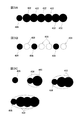
- 3A to 3C are diagrams showing an example of the arrangement of the ink dots formed in this example.
- FIG. 3A shows an example of the arrangement of dots during continuous ejection.
- FIG. 3B shows an example of the arrangement of dots during discrete ejection.
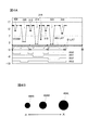
- FIG. 4A is a diagram for explaining a case where printing is performed with a configuration different from that of this example, and shows an example of a drive signal when a plurality of types of sizes of dots are used.
- FIG. 4B shows an example of ink dots formed in response to the drive signal.
- FIG. 1A shows an example of an inkjet printer 10 according to an embodiment of the present invention.
- FIG. 1A shows an example of the configuration of the inkjet printer 10.
- the inkjet printer 10 is a printing apparatus that performs printing on a medium 50 by an inkjet method, and includes a head unit 102, a plurality of rollers 106, a main scanning drive unit 108, and a control unit 104.
- the head part 102 is a part having a plurality of inkjet heads.
- the head unit 102 includes inkjet heads 202m, 202c, 202y, and 202k for each color of M (magenta), C (cyan), Y (yellow), and K (black). Color printing is performed by the head.
- the plurality of rollers 106 are rollers that convey the medium 50 in a preset conveyance direction.
- the plurality of rollers 106 is an example of a sub-scanning drive unit, and the head unit 102 is moved in a predetermined sub-scanning direction relative to the medium 50 by conveying the medium 50 in the conveyance direction.
- the main scanning driving unit 108 is a driving unit configured by a guide rail, a motor, and the like, and performs scanning in the main scanning direction orthogonal to the sub-scanning direction (main scanning, Scan) is performed by the head unit 102.
- the control unit 104 is a part that controls the printing operation by the inkjet printer 10.
- the control unit 104 moves the head unit 102 in the main scanning direction and the sub-scanning direction on the medium 50 by controlling the operations of the plurality of rollers 106 and the main scanning driving unit 108, for example.
- the control unit 104 controls the head unit 102 via the main scanning drive unit 108 to discharge ink droplets from each inkjet head of the head unit 102 that moves in the main scanning direction.
- each inkjet head in the head unit 102 ejects ink droplets at each position on the medium 50 according to the image to be printed while moving in a preset scanning direction.
- each of these inkjet heads has a plurality of nozzle rows arranged in the sub-scanning direction.
- the inkjet heads are arranged in the main scanning direction, and eject ink droplets from the nozzles constituting the nozzle row while moving at the same speed during the main scanning.
- the ink jet heads 202m, 202c, 202y, and 202k for each color are binary heads that perform printing in a two-gradation operation.
- a binary head is, for example, an inkjet that performs printing with a two-gradation operation of forming an ink dot or not forming an ink dot dot at the position of each pixel constituting an image to be printed. Head.
- the binary head may be an ink-jet head (ND head) in which the size of ink dots formed on the medium 50 by ejecting ink droplets onto the medium 50 is one type (Normal Dot).
- one type of dot size of ink formed on the medium 50 by ejecting ink droplets corresponds to, for example, a plurality of dots as a drive signal (driving waveform) for ejecting ink droplets to the inkjet head.
- a waveform signal for forming dots of one kind of size under a certain discharge condition is used. The relationship between the drive signal used in this example and ink droplet ejection will be described in more detail later.
- FIG. 1B shows an example of a detailed configuration of the control unit 104.
- the control unit 104 includes a print image processing unit 112, a scanning control unit 114, and an ejection control unit 116.
- each part or a part of function of the control part 104 may be implement
- a part of the configuration of the control unit 104 (for example, a part of the ejection control unit 116) may be provided at a position closer to the head unit 102, for example, in the guide rail.
- the print image processing unit 112 is a processing unit that performs image processing according to the configuration of the inkjet printer 10 on an image to be printed.
- the print image processing unit 112 receives image data to be printed from an external host PC, and performs necessary image processing in accordance with, for example, a print condition set by the user.
- the print image processing unit 112 may further perform image forming processing such as RIP processing in accordance with the configuration of the inkjet heads 202m, 202c, 202y, and 202k in the head unit 102, for example.
- image forming processing such as RIP processing in accordance with the configuration of the inkjet heads 202m, 202c, 202y, and 202k in the head unit 102, for example.
- data after the image forming process may be received from the host PC, and only necessary image processing may be performed thereafter.
- the print image processing unit 112 performs a process of identifying a highlight portion that is an area brighter than a preset brightness for an image to be printed. For example, in the image forming process, the image process is performed so that the ink dots are not continuously formed in the main scanning direction in the highlight portion.
- the fact that ink dots are not continuously formed in the main scanning direction means, for example, that ink dots are not formed side by side at adjacent dot positions in the main scanning direction.
- the dot position is the position of each pixel constituting the image to be printed.
- the print image processing unit 112 may receive, for example, data after performing such image processing from the host PC. Further, the ejection of ink droplets to the highlight portion will be described in more detail later.
- the scanning control unit 114 performs scanning control for moving the head unit 102 relative to the medium 50.
- the control unit 104 moves the head unit 102 in the main scanning direction and the sub-scanning direction on the medium 50 by controlling the operations of the plurality of rollers 106 and the main scanning driving unit 108, for example.
- the ejection control unit 116 controls ejection of ink droplets by each inkjet head.
- the ejection control unit 116 includes a drive signal output unit 118 and a drive timing control unit 120.
- the drive signal output unit 118 is a signal output unit that outputs a drive signal that causes the inkjet head to eject ink droplets.
- the drive signal output unit 118 discharges ink droplets from the nozzles of each inkjet head by outputting a drive signal to each inkjet head of the head unit 102 during main scanning.
- the drive timing control unit 120 controls the output timing of the drive signal by the discharge control unit 116.
- the drive timing control unit 120 causes each inkjet head to output a drive signal to the drive signal output unit 118 in accordance with control by the scan control unit 114 during main scanning of the head unit 102. Ink droplets are ejected to each position above.
- the drive timing control unit 120 selects a nozzle that should eject ink droplets from the nozzle row of each inkjet head based on data after image processing by the print image processing unit 112, for example. . Then, the selected nozzle receives the drive signal output from the drive signal output unit 118. Accordingly, the drive timing control unit 120 causes each inkjet head to eject ink droplets at a timing according to the image to be printed.
- FIG. 2A shows an example of a drive signal used in this example.
- a waveform VCOM indicates a waveform of a drive signal supplied to a nozzle that ejects ink droplets.
- the drive signal is supplied to the nozzle means, for example, that the drive signal is supplied to a drive element (such as a piezo element or a heating element) that ejects ink droplets from the nozzle.
- the waveform VCOM of the drive signal includes a state of a predetermined positive voltage (for example, about 14 to 16 V) and a state of a plurality of valleys 302, 304, and 306 in which the voltage is lower than the positive voltage. Signal.
- the valley 302 is a voltage fluctuation portion for causing the ink jet head to eject ink droplets.
- the control unit 104 first reduces the voltage to about 1V or less.
- the ink such as the meniscus at the nozzle position is temporarily drawn in the direction opposite to the ejection direction. Thereafter, by returning the voltage of the drive signal to a predetermined positive voltage, ink is pushed out in the ejection direction, and ink droplets are ejected from the nozzle to the medium.
- the valley 304 is a voltage fluctuation portion for preventing the meniscus from drying by adjusting the vibration of the ink.
- the control unit 104 temporarily reduces the voltage at the valley 304 by about 3 to 5V.
- a trough 306 is a voltage fluctuation portion for suppressing ink vibration.
- the control unit 104 temporarily reduces the voltage at the valley 306 by about 6 to 9V.
- ink droplets can be appropriately ejected by voltage fluctuations corresponding to the valleys 302. Further, by suppressing the vibration of the ink by the voltage fluctuation corresponding to the valley 306 thereafter, for example, the next ejection of the ink droplet can be performed more stably.
- the depth of the valley 306 does not completely suppress the vibration of the ink, but a constant vibration remains at the timing of ejecting the ink droplet to the position of the next pixel. Further, depending on the magnitude of ink vibration caused by ink droplet ejection, for example, as shown by a broken line in the figure, voltage fluctuation due to the valley 306 may be omitted.
- FIG. 2A shows waveforms of signals MN_LAT, D_LAT, and AN0 to AN3 in addition to the drive signal waveform VCOM.
- MN_LAT is a control signal for generating the waveform VCOM of the drive signal.
- D_LAT is a control signal indicating a period during which the drive signal is supplied.
- AN0 to AN3 are control signals for designating nozzles that should eject ink droplets in the nozzle row.
- the control unit 104 designates nozzles to which ink droplets are to be ejected by AN0 to AN1 according to the image to be printed. Then, by supplying a drive signal to designated nozzles, ink droplets are ejected from these nozzles. Also, ink droplets are not ejected by not supplying drive signals to nozzles that are not specified. In this way, for example, ink droplets can be appropriately ejected to each position on the medium in accordance with the image to be printed.
- FIG. 2B is a diagram showing an example of ink droplet ejection timing, and shows an example of the relationship between the ink ejection timing and the vibration cycle of the ink meniscus.
- a curve indicated by a solid line shows an example of a state of meniscus vibration that occurs when an ink droplet is ejected once and the next ink droplet is not ejected.
- a broken line shows an example of a state of meniscus vibration that occurs when an ink droplet is ejected once and then ejected continuously to the positions of pixels that are continuously arranged in the main scanning direction.
- the ink meniscus is once drawn to the side opposite to the ejection direction at the timing when the voltage drops at the valley 302 of the waveform VCOM of the drive signal. Therefore, at this timing, the meniscus displacement greatly moves to the side opposite to the ejection direction. Thereafter, the meniscus moves greatly toward the ejection side at the timing when the voltage rises at the valley 302 of the waveform VCOM of the drive signal. Then, at the timing T1 that is most displaced to the ejection side, the inkjet head ejects ink droplets from the nozzles.
- the meniscus vibrates at a constant cycle while gradually reducing the amplitude for a while.
- This cycle is a unique cycle determined by, for example, the structure of the nozzle and the ink chamber in the preceding stage of the nozzle.
- the meniscus vibration has a period in which the bottom peak comes at timings T2, T2, and T4.
- the drive timing control unit 120 causes the drive signal output unit 118 to output a drive signal at the resonance timing.
- the resonance timing is, for example, the timing at which the ink jet head ejects ink droplets in a state of resonating with respect to the oscillation cycle of the ink meniscus at the nozzle position.
- outputting the drive signal at the resonance timing means, for example, outputting the drive signal so that the ink jet head ejects ink droplets at the timing when the vibrating meniscus moves to the ejection side.
- the drive timing control unit 120 causes the drive signal output unit 118 to output a drive signal at the resonance timing.
- the timing at which the vibrating meniscus moves to the discharge side is the timing at which the meniscus first moves to the discharge side after the previous ink droplet discharge.
- each of the bottom peak timings T2, T3, and T4 of the vibration indicated by the solid line in the drawing is the second and subsequent ejection timings. Therefore, in the case of the vibration indicated by the broken line in the figure, immediately before these timings, the meniscus is once drawn to the side opposite to the ejection direction in accordance with the voltage fluctuation in the valley 302 of the drive signal. After that, it moves greatly in the discharge direction.
- the meniscus vibration period generated by the previous ink droplet ejection and the meniscus movement generated by the drive signal valley 302 are in a resonant state, so that the amount of displacement when the meniscus is pulled in , And the amount of displacement at the time of discharge are larger than those at the time of the first discharge corresponding to the case of no resonance.
- the volume of the ejected ink droplet is larger than that during the first ejection.
- the dots of ink formed are also increased.
- the ink droplet can be ejected in a state where the amplitude of the meniscus vibration is large.
- this makes it possible to appropriately eject a large volume of ink droplets.
- the ink droplets are ejected at the minimum period that can eject the ink droplets at the resonance timing. Therefore, according to this example, it is possible to use a drive signal with a short cycle, for example. Thereby, the printing speed can be improved more appropriately.
- the drive signal output unit 118 ejects the second and subsequent ink droplets according to the drive signal at the resonance timing.
- the drive signal at the first discharge does not become a drive signal at the resonance timing.
- the drive timing control unit 120 can cause the drive signal output unit 118 to output a drive signal at a non-resonant timing in addition to the resonance timing.
- the non-resonant timing is a timing at which the ink-jet head ejects ink droplets in a state where it does not resonate with the meniscus vibration period.
- the non-resonant timing may be a discharge timing other than the second and subsequent discharges during continuous discharge. That is, when an ink droplet is ejected to the immediately preceding dot position during main scanning, the ejection of the ink droplet to the next dot position is automatically ejected at the resonance timing. Further, when an ink droplet is not ejected to the immediately preceding dot position, the ejection of the ink droplet to the next dot position is automatically ejected at a non-resonant timing.
- the drive timing control unit 120 sets the resonance timing and the non-resonance timing for the ejection of the ink droplet to each dot position depending on whether or not the ink droplet is ejected to the immediately preceding dot position. Select either one automatically. In addition, this selection is performed according to the arrangement of dot positions for ejecting ink droplets based on, for example, data received from the print image processing unit 112.
- the drive timing control unit 120 selects non-resonant timing.
- the drive timing control unit 120 selects the non-resonant timing when performing the first discharge other than during continuous discharge or during continuous discharge.
- the drive timing control unit 120 selects the resonance timing.
- the drive signal output unit 118 causes the drive signal output unit 118 to output a drive signal at the selected timing.
- the volume of the ink droplet ejected in response to the resonance timing drive signal is larger than the volume of the ink droplet ejected in response to the non-resonance timing drive signal. large.
- the inkjet head forms the first size dots by the ejected ink droplets.
- the inkjet head forms dots of a second size smaller than the first size by the ejected ink droplets. Therefore, according to this example, it is possible to form a plurality of types of ink dots of the first size and the second size by using one type of drive signal, for example.
- the resonance timing and the non-resonance timing are distinguished for the drive signals output at the same timing in the actual time according to the arrangement of the formed ink dots.
- the resonance timing and the non-resonance timing may be distinguished by changing the output timing in the actual time.
- the drive timing control unit 120 selects a resonance timing or a non-resonance timing for each dot position for ejecting ink droplets based on data received from the print image processing unit 112. Then, the output timing of the drive signal is varied according to the selection.
- FIG. 3A to 3C show an example of the arrangement of the ink dots formed in this example.
- FIG. 3A shows an example of the arrangement of dots during continuous ejection.
- FIG. 3B shows an example of the arrangement of dots when ink droplets are not continuously ejected to adjacent dot positions in the main scanning direction (hereinafter referred to as discrete ejection).
- the first discharge is performed at a non-resonant timing. Therefore, in this case, a small size (second size) dot 406 is formed.
- the second and subsequent discharges are performed at the resonance timing. Therefore, in this case, a dot 402 having a size (first size) larger than the dot 406 at the non-resonant timing is formed.
- the arrangement of dots in the main scanning direction is configured such that large dots 402 are successively arranged after one small dot 406.
- a dot having a large size can be appropriately formed by using the dot 402 formed by the drive signal at the resonance timing.
- the dot 402 may be a dot having a size connected to at least a part of the dots arranged adjacent to each other in the main scanning direction. Further, the adjacent dots 402 may be spread and integrated on the medium, for example. With such a configuration, according to this example, it is possible to perform printing of the solid portion at high speed and appropriately.
- a non-resonant dot 406 having a smaller size can be used as a dot used when printing a highlight portion. Therefore, according to the present example, it is possible to realize good gradation expression in the highlight portion. In addition, this makes it possible to perform high-speed and appropriate printing even for the highlight portion.
- high-speed and appropriate printing can be performed on both the solid portion and the highlight portion. Further, since dots 402 and 406 having different sizes can be used, high-speed and appropriate printing can be performed even in a halftone area other than the solid part and the highlight part. Therefore, according to this example, for example, high-speed printing and good gradation expression can be appropriately achieved.
- FIG. 3C shows an example of various collective dot configurations.
- FIG. 4A and 4B are diagrams for explaining the effect obtained by this example in more detail.
- FIG. 4A is a diagram for explaining a case where printing is performed with a configuration different from that of this example, and shows an example of a drive signal when a plurality of types of sizes of dots are used.
- a signal with the same label as in FIG. 2A is a signal used for the same purpose as the signal with the same label in FIG. 2A.
- FIG. 4B shows an example of ink dots formed in response to the drive signal.
- dots 404S small balls
- 404M medium balls
- 404L shown in FIG. 4B.
- a drive signal hereinafter referred to as a multi-value drive signal
- This multi-valued drive signal is a signal composed of a plurality of pulses respectively corresponding to dots of each size.
- the waveform VCOM of the multi-level drive signal is a signal including a predetermined positive voltage state and a plurality of valleys 308 to 322 in which the voltage is lower than the positive voltage. is there.
- valleys 310, 314, and 320 are voltage fluctuations corresponding to ejection of another ink droplet, respectively, and are similar to the valley 302 in the drive signal shown in FIG. 2A.
- Ink droplets are ejected from the medium to the medium.
- the other valleys 308, 312, 314, 316, and 322 are voltage fluctuations for controlling ink vibration, for example, similarly to the valleys 304 and 306 in the drive signal shown in FIG. 2A.
- ink droplets can be ejected up to three times for one cycle of the drive signal.
- nozzles AN0 to AN1 that perform actual ejection for each ejection time, it is possible to form ink dots of various sizes by varying the number of ejection times of each nozzle. .
- small dots 404S are formed by causing each nozzle to perform only the first discharge corresponding to the valley 310. Further, by causing only the third discharge corresponding to the valley 320 to be performed, the medium-sized dots 404M are formed. Further, only the first and second discharges corresponding to the valley 310 and the valley 314 are performed to form a large-sized dot 404L.
- the cycle of the multi-valued drive signal is longer than the cycle of the drive signal shown in FIG. 2A (hereinafter referred to as the drive signal in FIGS. 2A and 2B) as a result of corresponding to a plurality of ejections.
- the period of the drive signal in FIGS. 2A and 2B is a period corresponding to a frequency of about 45 kHz, and is about 22 ⁇ s (for example, about 18 to 25 ⁇ s).
- the cycle of the multi-valued drive signal is a cycle corresponding to a frequency of about 15 kHz, and is about 67 ⁇ s (for example, about 60 to 75 ⁇ s), which is about three times the cycle of the drive signal in FIGS. 2A and 2B. ing.
- the moving speed of the inkjet head during main scanning is about 1/3 as compared with the case of using the drive signals of FIGS. 2A and 2B.
- the printing speed is reduced as compared with the case where the drive signal of FIGS. 2A and 2B is used.
- good gradation expression can be realized, but the printing speed is lowered. Therefore, it is difficult to achieve both high-speed printing and good gradation expression.
- ink droplets are ejected at the resonance timing and the non-resonance timing.
- the present invention can be suitably used for an inkjet printer, for example.
Landscapes
- Ink Jet (AREA)
- Particle Formation And Scattering Control In Inkjet Printers (AREA)
Description
本発明は、インクジェットプリンタ及び印刷方法に関する。
従来、インクジェットプリンタについて、階調印刷(階調印字)を行う構成が知られている(例えば、特許文献1参照)。例えば、特許文献1には、背景技術として、液体吐出ヘッド(インクジェットヘッド)から大きさの異なる滴、例えば大滴、中滴、小滴を吐出させることができるようにして、大きさの異なるドットを形成できるようにした構成が記載されている。また、特許文献1の例えば[0080]段落には、大きさの異なるドットを形成するための構成として、液滴の吐出を制御する駆動波形(駆動信号)について、1印刷周期内に各サイズのドットを形成するためのパルスを含む信号を用いることが記載されている。
インクジェットプリンタは、媒体(メディア)に対してインクジェットヘッドを移動(走査)させつつ、印刷する画像を構成する各画素の位置であるドット位置へインク滴を吐出する。そして、この動作中、インクジェットの走査方向において隣接するドット位置へインク滴を吐出する時間間隔(最少吐出周期)は、少なくとも、駆動信号の周期以上にする必要がある。そのため、高い解像度の画像を高速に印刷するためには、駆動信号の周期を短くすることが必要である。
しかし、例えば、特許文献1のような方法で階調印刷を行う場合、各サイズのドットに対応するパルスを含む駆動信号を用いるため、駆動信号の周期が長くなる。そして、駆動信号の周期が長くなった場合、その長さに応じて、インクジェットヘッドの走査速度を遅くするか、印刷の解像度を低下させることが必要となる。
そのため、従来の方法で階調印刷を行う場合、高速での印刷を行うことは困難である。一方で、より周期の短い駆動信号を用いた場合、従来知られている方法では、階調表現が不十分になるおそれがある。そこで、本発明は、上記の課題を解決できるインクジェットプリンタ及び印刷方法を提供することを目的とする。
従来の階調印刷と比べて高速に印刷を行うためには、上記のとおり、より周期の短い駆動信号を用いることが考えられる。より具体的には、例えば、複数サイズ(径)のドット(VD:Variable Dot)に対応するパルスを含む駆動信号ではなく、1種類のサイズ(径)のドットのみ
(ND:Normal Dot)に対応するパルスを含む駆動信号を用いることが考えられる。そこで、本願の発明者は、先ず、このような駆動信号を用いる場合の好ましい構成について、鋭意研究を行った。
(ND:Normal Dot)に対応するパルスを含む駆動信号を用いることが考えられる。そこで、本願の発明者は、先ず、このような駆動信号を用いる場合の好ましい構成について、鋭意研究を行った。
インクジェットプリンタにおいては、通常、インクのドットを並べて形成することで領域内を塗りつぶすベタ印刷が可能であることが求められる。そして、高速でのベタ印刷を可能にするためには、大きなサイズのドットを形成可能であることが必要となる。
すなわち、形成されるインクのドットが小さい場合、通常の印刷解像度で印刷を行うだけでは領域内を塗りつぶせないおそれがある。そして、この場合、ベタ印刷を行うためには、より狭い間隔でドットを並べるために、ベタ印刷時の印刷解像度を通常の印刷時よりも高めることが必要となる。しかし、この場合、ベタ印刷に要する時間が増大し、印刷速度が低下することとなる。
一方、形成されるインクのドットが十分に大きい場合、通常の印刷解像度で印刷を行うだけで領域内を塗りつぶせるため、高速にベタ印刷を行うことが可能となる。そのため、1種類のサイズのドットのみに対応するパルスを含む駆動信号を用いる場合、高速に印刷を行うには、この駆動信号に応じて形成されるインクのドットのサイズを十分に大きくすることが必要である。
ここで、駆動信号に応じて形成されるインクのドットのサイズを大きくするためには、例えば、高い電圧の信号を用いること等も考えられる。しかし、駆動信号の電圧を高めた場合、インクジェットヘッドの耐久性に影響が生じることも考えられる。また、使用可能な回路素子が制限され、コスト上昇の要因になるおそれもある。また、パルスの立ち上がり及び立ち下がりに要する時間が長くなるため、駆動信号の周期も長くなる。そのため、より適切な方法でより大きなサイズのドットを形成することが望まれる。
この点について、本願の発明者は更に鋭意研究を行い、インク滴の吐出時にノズル位置に生じるメニスカスの振動に着目をした。そして、メニスカスが振動している状態において、その振動と共振するタイミングで次のインク滴を吐出することで、大きなサイズのドットを適切に形成できることを見出した。これらの知見に基づいて本願の発明者が想到した本発明は、以下の構成を有する。
(構成1)インクジェット方式で印刷を行うインクジェットプリンタであって、ノズルから媒体へインク滴を吐出するインクジェットヘッドと、インクジェットヘッドによるインク滴の吐出を制御する吐出制御部とを備え、吐出制御部は、インクジェットヘッドにインク滴を吐出させる駆動信号を出力する駆動信号出力部と、駆動信号出力部が駆動信号を出力するタイミングを制御する制御部であり、ノズルの位置におけるインクのメニスカスの振動の周期に対して共振する状態でインクジェットヘッドがインク滴を吐出するタイミングである共振タイミングで、駆動信号出力部に駆動信号を出力させる駆動タイミング制御部とを有する。
駆動タイミング制御部は、共振タイミングの駆動信号として、例えば、振動しているインクのメニスカスが吐出側へ動くタイミングでインク滴の吐出をさせる駆動信号を、駆動信号出力部に出力させる。振動しているインクのメニスカスとは、例えば、前回のインク滴の吐出により振動しているインクのメニスカスである。また、インクのメニスカスが吐出側へ動くタイミングは、前回のインク滴の吐出後、メニスカスが最初に吐出側に動くタイミングであることが好ましい。
このように構成した場合、駆動信号として、例えば、複数サイズのドットに対応するパルスを含む駆動信号ではなく、インクジェットヘッドに1回の吐出をさせる駆動信号(例えば、1種類のサイズのドットのみに対応するパルスを含む駆動信号)を用いることができる。そのため、このように構成すれば、例えば、高速な印刷を適切に行うことが可能になる。
また、このように構成した場合、メニスカスの振動との共振の結果、インクジェットヘッドは、共振していない場合と比べて容量の大きなインク滴を吐出する。また、その結果、形成されるインクのドットも大きくなる。そのため、このように構成すれば、更に、ベタ印刷を高速かつ適切に行うことができる。
(構成2)タイミング制御部は、共振タイミングの他に、メニスカスの振動の周期に対して共振しない状態でインクジェットヘッドがインク滴を吐出する非共振タイミングでも、駆動信号出力部に駆動信号を出力させることが可能であり、少なくとも共振タイミング及び非共振タイミングを含む複数のタイミングからいずれかのタイミングを選択して、選択したタイミングで、駆動信号出力部に駆動信号を出力させ、共振タイミングで出力される駆動信号に応じてインク滴を吐出する場合、インクジェットヘッドは、吐出するインク滴により、第1のサイズのドットを形成し、非共振タイミングで出力される駆動信号に応じてインク滴を吐出する場合、インクジェットヘッドは、吐出するインク滴により、第1のサイズよりも小さい第2のサイズのドットを形成する。
1種類のサイズのドットのみを用いて印刷を行う場合において、ベタ印刷時の印刷速度を確保することを考えてドットのサイズを設定すると、サイズの大きなドット(大玉)にドットサイズが固定されることとなる。しかし、大玉のドットのみを用いて印刷を行う場合、明度の高い領域であるライト部(ハイライト部等)において、十分な階調表現ができない場合がある。
この問題に対しては、例えば、大玉、中玉、小玉等の複数のサイズのドットを印刷領域の明度に応じて打ち分けることも考えられる。しかし、この場合、従来の方法では、上記のように、複数サイズのドットに対応するパルスを含む駆動信号を用いることが必要となるため、印刷速度が低下するという問題が生じる。
これに対し、本願の発明者は、更に鋭意研究を行い、共振タイミングでのインクのドットを形成する場合と同じ駆動信号を用い、メニスカスの振動の周期と共振しない状態で駆動信号を出力させることにより、共振タイミングでの吐出時よりも小さなサイズのドットを形成できることを見出した。すなわち、複数サイズのドットに対応するパルスを含む駆動信号を用いるのではなく、共振タイミングにより形成される第1のサイズのドットのみに対応するパルスを含む駆動信号をそのまま用い、かつ、非共振タイミングで駆動信号を出力することで、第1のサイズよりも小さい第2のサイズのドットの形成が可能となることを見出した。
このように構成した場合、周期の長い駆動信号を用いる必要がないため、例えば、高速に印刷を行うことが可能になる。また、第1のサイズの他に第2のサイズのインクのドットが形成可能になるため、より良好な階調表現を実現できる。従って、このように構成すれば、例えば、高速な印刷と、良好な階調表現とを、適切に両立できる。
(構成3)インクのドットを並べて形成することで塗りつぶす領域であるベタ部に対して印刷を行う場合、駆動タイミング制御部は、駆動信号出力部に、共振タイミングで駆動信号を出力させ、予め設定された明度より明るい領域であるハイライト部に対して印刷を行う場合、駆動タイミング制御部は、駆動信号出力部に、非共振タイミングで駆動信号を出力させる。
このように構成した場合、サイズの大きい第1のサイズのインクのドットを用いることにより、ベタ部の印刷を高速かつ適切に行うことができる。また、サイズの小さい第2のサイズのインクのドットを用いることにより、ハイライト部の階調表現をより良好にできる。そのため、このように構成すれば、例えば、高速な印刷と、良好な階調表現とを、適切に両立できる。
(構成4)共振タイミングで出力される駆動信号に応じてインク滴を吐出する場合、インクジェットヘッドは、少なくとも一の方向において隣接して並ぶインクのドットが少なくとも一部においてつながるサイズのドットを形成する。隣接して並ぶドットは、例えば媒体上で一体化してもよい。このように構成すれば、例えば、ベタ印刷をより適切に行うことができる。
(構成5)インクジェットヘッドは、印刷する画像を構成する各画素の位置であるドット位置へ、予め設定された走査方向へ媒体に対して相対的に移動しつつ、ノズルからインク滴を吐出し、インクジェットヘッドが、走査方向へ連続して並ぶ複数のドット位置へ連続してインク滴を吐出する場合、少なくとも2回目以降のインク滴を吐出させる駆動信号について、駆動タイミング制御部は、共振タイミングで、駆動信号出力部に駆動信号を出力させる。このように構成すれば、共振タイミングでの駆動信号の出力を、より適切に行うことができる。
(構成6)インクジェットヘッドが、走査方向へ連続して並ぶ複数のドット位置へ連続してインク滴を吐出する場合、2回目以降のインク滴を吐出させる駆動信号について、駆動タイミング制御部は、前回のインク滴の吐出後に生じるメニスカスの振動において、最初にメニスカスが吐出側へ動くタイミングでインク滴の吐出をさせる駆動信号を、駆動信号出力部に出力させる。
このように構成した場合、前回の吐出により生じたメニスカスの振動の振幅が大きい状態で、次のインク滴を吐出できる。そのため、このように構成すれば、例えば、共振タイミングでのインク滴の吐出により、容量の大きなインク滴をより適切に吐出できる。
また、この場合、共振タイミングによりインク滴を吐出可能な最小の周期でインク滴を吐出することになる。そのため、このように構成すれば、例えば、より短い周期の駆動信号を用いることが可能になる。また、これにより、印刷速度をより適切に向上させることができる。
(構成7)インクジェットヘッドは、印刷する画像を構成する各画素の位置に対して、インクのドットを形成するか、又は、インクドットドットを形成しないかの2階調の動作で印刷を行う2値ヘッドである。このように構成すれば、例えば、高速での印刷を適切に行うことができる。
(構成8)インクジェット方式で印刷を行う印刷方法であって、ノズルから媒体へインク滴を吐出するインクジェットヘッドを用い、インクジェットヘッドによるインク滴の吐出を制御する吐出制御を行い、吐出制御において、インクジェットヘッドにインク滴を吐出させる駆動信号を出力する駆動信号出力制御と、駆動信号を出力するタイミングの制御であり、ノズルの位置におけるインクのメニスカスの振動の周期に対して共振する状態でインクジェットヘッドがインク滴を吐出するタイミングである共振タイミングで、駆動信号を出力させる駆動タイミング制御とを行う。このようにすれば、例えば、構成1と同様の効果を得ることができる。
本発明によれば、例えば、高速な印刷を適切に行うことが可能になる。
以下、本発明に係る実施形態を、図面を参照しながら説明する。図1Aおよび図1Bは、本発明の一実施形態に係るインクジェットプリンタ10の一例を示す。図1Aは、インクジェットプリンタ10の構成の一例を示す。
本例において、インクジェットプリンタ10は、媒体(メディア)50に対してインクジェット方式で印刷を行う印刷装置であり、ヘッド部102、複数のローラ106、主走査駆動部108、及び制御部104を備える。
ヘッド部102は、複数のインクジェットヘッドを有する部分である。本例において、ヘッド部102は、M(マゼンタ)、C(シアン)、Y(イエロー)、及びK(ブラック)の各色のインクジェットヘッド202m、202c、202y、202kを有しており、これらのインクジェットヘッドにより、カラー印刷を行う。
複数のローラ106は、予め設定された搬送方向へ媒体50を搬送するローラである。本例において、複数のローラ106は、副走査駆動部の一例であり、搬送方向へ媒体50を搬送することにより、ヘッド部102を、媒体50に対して相対的に、所定の副走査方向へ移動させる。主走査駆動部108は、ガイドレール及びモータ等から構成されている駆動部であり、媒体50の被印刷面と平行な面内で副走査方向と直交する主走査方向への走査(主走査、スキャン)をヘッド部102に行わせる。
制御部104は、インクジェットプリンタ10による印刷動作を制御する部分である。本例において、制御部104は、例えば、複数のローラ106及び主走査駆動部108の動作を制御することにより、媒体50上の主走査方向及び副走査方向へヘッド部102を移動させる。また、本例において、制御部104は、主走査駆動部108を介してヘッド部102を制御することにより、主走査方向へ移動するヘッド部102の各インクジェットヘッドから、インク滴を吐出させる。これにより、主走査時において、ヘッド部102における各インクジェットヘッドは、予め設定された走査方向へ移動しつつ、媒体50上の各位置において、印刷する画像に応じて、インク滴を吐出する。
ここで、本例において用いる各色のインクジェットヘッド202m、202c、202y、202kについて、詳しく説明する。本例において、これらの各インクジェットヘッドは、副走査方向へ並ぶ複数のノズル列を有する。また、各インクジェットヘッドは、主走査方向に並んでおり、主走査時において、同じ速度で移動しつつ、ノズル列を構成するノズルから、インク滴を吐出する。
また、本例において、各色のインクジェットヘッド202m、202c、202y、202kは、2階調の動作で印刷を行う2値ヘッドである。2値ヘッドとは、例えば、印刷する画像を構成する各画素の位置に対して、インクのドットを形成するか、又は、インクドットドットを形成しないかの2階調の動作で印刷を行うインクジェットヘッドである。2値ヘッドは、媒体50へのインク滴の吐出により媒体50上に形成するインクのドットのサイズが1種類(Normal Dot)のインクジェットヘッド(NDヘッド)であってよい。この場合、インク滴の吐出により媒体50上に形成するインクのドットのサイズが1種類とは、例えば、インクジェットヘッドにインク滴を吐出させる駆動信号(駆動波形)として、複数サイズのドットに対応するパルスを含む信号ではなく、一定の吐出条件下において1種類のサイズのドットを形成するための波形の信号を用いることである。本例において用いる駆動信号と、インク滴の吐出との関係については、後に、更に詳しく説明をする。
図1Bは、制御部104の詳細な構成の一例を示す。本例において、制御部104は、印刷画像処理部112、走査制御部114、及び吐出制御部116を有する。尚、制御部104の各部又は一部の機能は、例えばインクジェットプリンタ10のファームウェアに基づき、CPU等により実現されてもよい。また、制御部104の構成のうち、一部の構成(例えば、吐出制御部116の一部等)は、例えばガイドレール内等の、ヘッド部102により近い位置に設けられてもよい。
印刷画像処理部112は、印刷する画像に対し、インクジェットプリンタ10の構成に応じた画像処理を行う処理部である。印刷画像処理部112は、例えば、印刷すべき画像のデータを外部のホストPCから受け取り、例えばユーザにより設定された印刷条件に合わせて、必要な画像処理を行う。また、この場合、印刷画像処理部112は、例えば、ヘッド部102におけるインクジェットヘッド202m、202c、202y、202kの構成に合わせて、RIP処理等の画像形成処理を更に行ってもよい。また、画像形成処理後のデータをホストPCから受け取り、その後に必要な画像処理のみを行ってもよい。
また、本例において、印刷画像処理部112は、印刷する画像について、予め設定された明度より明るい領域であるハイライト部を識別する処理を行う。そして、例えば画像形成処理において、ハイライト部内で主走査方向において連続してインクのドットが形成されないように、画像処理を行う。主走査方向において連続してインクのドットが形成されないとは、例えば、主走査方向において隣接するドット位置に並んでインクのドットが形成されないことである。また、ドット位置とは、印刷する画像を構成する各画素の位置である。
尚、印刷画像処理部112は、例えば、このような画像処理を行った後のデータを、ホストPCから受け取ってもよい。また、ハイライト部に対するインク滴の吐出については、後に更に詳しく説明をする。
走査制御部114は、媒体50に対して相対的にヘッド部102を移動させる走査の制御を行う。本例において、制御部104は、例えば、複数のローラ106及び主走査駆動部108の動作を制御することにより、媒体50上の主走査方向及び副走査方向へ、ヘッド部102を移動させる。
吐出制御部116は、各インクジェットヘッドによるインク滴の吐出の制御を行う。本例において、吐出制御部116は、駆動信号出力部118及び駆動タイミング制御部120を有する。駆動信号出力部118は、インクジェットヘッドにインク滴を吐出させる駆動信号を出力する信号出力部である。本例において、駆動信号出力部118は、主走査時にヘッド部102の各インクジェットヘッドへ駆動信号を出力することにより、各インクジェットヘッドのノズルから、インク滴を吐出させる。
駆動タイミング制御部120は、吐出制御部116による駆動信号の出力のタイミングを制御する。本例において、駆動タイミング制御部120は、ヘッド部102の主走査時において、走査制御部114による制御に合わせて駆動信号出力部118に駆動信号を出力させることにより、各インクジェットヘッドに、媒体50上の各位置へ、インク滴を吐出させる。
尚、主走査時において、駆動タイミング制御部120は、例えば、印刷画像処理部112による画像処理後のデータに基づき、各インクジェットヘッドのノズル列の中から、インク滴を吐出すべきノズルを選択する。そして、駆動信号出力部118が出力する駆動信号を、選択したノズルに受け取らせる。これにより、駆動タイミング制御部120は、印刷する画像に応じたタイミングで、各インクジェットヘッドに、インク滴を吐出させる。
続いて、駆動信号と、インク滴の吐出との関係について更に詳しく説明をする。図2Aおよび図2Bは、駆動信号及びインク滴の吐出のタイミングの一例を示す。図2Aは、本例において用いる駆動信号の一例を示す。
図において、波形VCOMは、インク滴を吐出するノズルへ供給される駆動信号の波形を示す。駆動信号がノズルへ供給されるとは、例えば、ノズルからインク滴を吐出させる駆動素子(ピエゾ素子又は加熱素子等)に駆動信号が供給されることである。また、本例において、駆動信号の波形VCOMは、所定の正電圧(例えば14~16V程度)の状態と、この正電圧と比べて電圧が低下する複数の谷302、304、306の状態とを含む信号である。
谷302は、インクジェットヘッドにインク滴を吐出させるための電圧変動の部分である。本例において、制御部104は、谷302において、先ず、電圧を、1V程度以下にまで一旦低下させる。これにより、ノズル位置のメニスカス等のインクを吐出方向と反対側へ一旦引き込む。また、その後、駆動信号の電圧を所定の正電圧に戻すことにより、インクを吐出方向へ押しだし、ノズルから媒体へインク滴を吐出させる。
谷304は、インクの振動を調整することでメニスカスの乾燥を防止させるための電圧変動の部分である。本例において、制御部104は、谷304において、電圧を、一旦、3~5V程度低下させる。また、谷306は、インクの振動を抑えるための電圧変動の部分である。本例において、制御部104は、谷306において、電圧を、一旦、6~9V程度低下させる。
本例によれば、例えば、谷302に対応する電圧変動により、インク滴を適切に吐出させることができる。また、その後谷306に対応する電圧変動によりインクの振動を抑えることにより、例えば、次回のインク滴の吐出をより安定して行うことが可能になる。
尚、本例においては、谷306の深さを、インクの振動を完全には抑えず、次の画素の位置へインク滴を吐出するタイミングにおいても一定の振動が残るようにしている。また、インク滴の吐出により生じるインクの振動の大きさによっては、例えば図中に破線で示すように、谷306による電圧変動を省略してもよい。
また、図2Aにおいては、駆動信号の波形VCOMの他に、MN_LAT、D_LAT、AN0~AN3の各信号の波形を示している。このうち、
MN_LATは、駆動信号の波形VCOMを生成するための制御信号である。D_LATは、駆動信号が供給されている期間を示す制御信号である。
MN_LATは、駆動信号の波形VCOMを生成するための制御信号である。D_LATは、駆動信号が供給されている期間を示す制御信号である。
また、AN0~AN3は、ノズル列においてインク滴を吐出すべきノズルを指定する制御信号である。本例において、制御部104は、印刷する画像に応じて、インク滴を吐出すべきノズルを、AN0~AN1により指定する。そして、指定したノズルに駆動信号を供給することにより、これらのノズルからインク滴を吐出させる。また、指定しなかったノズルには、駆動信号を供給しないことにより、インク滴を吐出させない。このようにすれば、例えば、媒体上において、印刷する画像に応じて、各位置にインク滴を適切に吐出できる。
図2Bは、インク滴の吐出のタイミングの一例を示す図であり、インク吐出のタイミングと、インクのメニスカスの振動周期との関係の一例を示す。図において、実線で示した曲線は、インク滴を1回吐出した後、次のインク滴を吐出しない場合に生じるメニスカスの振動の様子の一例を示す。また、破線は、インク滴を1回吐出した後、主走査方向へ連続して並ぶ画素の位置へ連続してインク滴を吐出する場合に生じるメニスカスの振動の様子の一例を示す。
実線で示した場合において、インクのメニスカスは、駆動信号の波形
VCOMの谷302において電圧が低下するタイミングで、吐出方向と反対側へ一旦引き込まれる。そのため、このタイミングにおいて、メニスカスの変位は、吐出方向と反対側へ大きく動く。また、その後、駆動信号の波形
VCOMの谷302において電圧が上昇するタイミングで、メニスカスは吐出側へ大きく動く。そして、吐出側へ最も変位するタイミングT1において、インクジェットヘッドは、ノズルから、インク滴を吐出する。
VCOMの谷302において電圧が低下するタイミングで、吐出方向と反対側へ一旦引き込まれる。そのため、このタイミングにおいて、メニスカスの変位は、吐出方向と反対側へ大きく動く。また、その後、駆動信号の波形
VCOMの谷302において電圧が上昇するタイミングで、メニスカスは吐出側へ大きく動く。そして、吐出側へ最も変位するタイミングT1において、インクジェットヘッドは、ノズルから、インク滴を吐出する。
また、インク滴の吐出後、メニスカスは、しばらくの間、徐々に振幅を小さくしながら、一定の周期で振動する。この周期は、例えばノズルや、ノズル前段のインク室の構造等によって決まる固有の周期である。また、図示した場合において、メニスカスの振動は、タイミングT2、T2、T4にボトムピークが来る周期を有している。
一方、本例において、主走査方向へ連続して並ぶ画素の位置へ連続してインク滴を吐出する場合、前回のインク滴の吐出によりメニスカスが振動している間に次のインク滴を吐出することになる。そのため、メニスカスの振動の周期と、インクを吐出する時間間隔との関係が重要になる。
そして、本例において、駆動タイミング制御部120は、駆動信号出力部118に、共振タイミングで駆動信号を出力させる。共振タイミングとは、例えば、ノズルの位置におけるインクのメニスカスの振動の周期に対して共振する状態でインクジェットヘッドがインク滴を吐出するタイミングである。また、共振タイミングで駆動信号を出力させるとは、例えば、振動しているインクのメニスカスが吐出側へ動くタイミングでインクジェットヘッドにインク滴を吐出させるように、駆動信号を出力させることである。これにより、例えば、主走査方向へ連続して並ぶ複数のドット位置へインクジェットヘッドが連続してインク滴を吐出する場合(以下、連続吐出時という)、2回目以降のインク滴を吐出させる駆動信号について、駆動タイミング制御部120は、共振タイミングで、駆動信号出力部118に駆動信号を出力させる。
ここで、本例において、振動しているインクのメニスカスが吐出側へ動くタイミングは、前回のインク滴の吐出後、メニスカスが最初に吐出側に動くタイミングである。このように構成すれば、例えば、振動を繰り返して振幅が小さくなる前に、次のインク滴を吐出させることができる。また、これにより、共振の状態をより適切に実現できる。
また、この場合、図中に実線で示した振動のボトムピークのタイミング
T2、T3、T4のそれぞれが2回目以降の各回の吐出のタイミングとなる。そのため、図中に破線で示した振動の場合、これらのタイミングの直前において、駆動信号の谷302における電圧変動に応じて、メニスカスは、吐出方向と反対側へ一旦引き込まれる。そして、その後、吐出方向へ大きく動く。
T2、T3、T4のそれぞれが2回目以降の各回の吐出のタイミングとなる。そのため、図中に破線で示した振動の場合、これらのタイミングの直前において、駆動信号の谷302における電圧変動に応じて、メニスカスは、吐出方向と反対側へ一旦引き込まれる。そして、その後、吐出方向へ大きく動く。
また、この場合、前回のインク滴の吐出により生じたメニスカスの振動の周期と、駆動信号の谷302により生じるメニスカスの動きとが同期して共振状態となるため、メニスカスが引き込まれる際の変位量、及び吐出時の変位量は、ともに、共振していない場合に相当する1回目の吐出時よりも大きくなる。そして、その結果、吐出されるインク滴の容量は、1回目の吐出時よりも大きくなる。また、形成されるインクのドットも大きくなる。
このように、本例によれば、メニスカスの振動と、インク滴の吐出タイミングとを同期させ、共振状態とすることにより、メニスカスの振動の振幅が大きい状態でインク滴を吐出できる。また、これにより、容量の大きなインク滴を適切に吐出できる。
また、この場合、共振タイミングによりインク滴を吐出可能な最小の周期 でインク滴を吐出することになる。そのため、本例によれば、例えば、短い周期の駆動信号を用いることが可能になる。また、これにより、印刷速度をより適切に向上させることができる。
ここで、上記において説明をしたとおり、連続吐出時において、駆動信号出力部118は、2回目以降のインク滴を、共振タイミングの駆動信号に応じて吐出する。しかし、1回目の吐出以前にはメニスカスが振動していないため、1回目の吐出時の駆動信号は、共振タイミングの駆動信号にならない。
そのため、本例において、駆動タイミング制御部120は、共振タイミングの他に、非共振タイミングでも、駆動信号出力部118に駆動信号を出力させることが可能であると言える。この場合、非共振タイミングとは、メニスカスの振動の周期に対して共振しない状態でインクジェットヘッドがインク滴を吐出するタイミングである。
また、実用上、非共振タイミングは、連続吐出時の2回目以降の吐出以外の場合の吐出のタイミングであってよい。すなわち、主走査時において、直前のドット位置へインク滴を吐出した場合、次のドット位置へのインク滴の吐出は、自動的に、共振タイミングでの吐出となる。また、直前のドット位置へインク滴を吐出しなかった場合、次のドット位置へのインク滴の吐出は、自動的に、非共振タイミングでの吐出となる。
そのため、本例において、駆動タイミング制御部120は、各ドット位置へのインク滴の吐出に対して、その直前のドット位置へのインク滴の吐出の有無に応じて、共振タイミング及び非共振タイミングのいずれかを、自動的に選択する。また、この選択を、例えば、印刷画像処理部112から受け取るデータに基づき、インク滴を吐出するドット位置の並びに応じて行う。
より具体的には、例えば、主走査時において、直前のドット位置へのインク滴の吐出を行わなかった場合、駆動タイミング制御部120は、非共振タイミングを選択する。これにより、連続吐出時以外、又は連続吐出時の1回目の吐出を行う場合に、駆動タイミング制御部120は、非共振タイミングを選択する。また、連続吐出時の2回目以降の吐出の場合、駆動タイミング制御部120は、共振タイミングを選択する。そして、駆動信号出力部118は、選択したタイミングで、駆動信号出力部118に駆動信号を出力させる。
また、上記においても説明をしたように、本例において、共振タイミングの駆動信号に応じて吐出されるインク滴の容量は、非共振タイミングの駆動信号に応じて吐出されるインク滴の容量よりも大きい。これにより、例えば、共振タイミングの駆動信号に応じてインク滴を吐出する場合、インクジェットヘッドは、吐出するインク滴により、第1のサイズのドットを形成する。また、非共振タイミングの駆動信号に応じてインク滴を吐出する場合、インクジェットヘッドは、吐出するインク滴により、第1のサイズよりも小さい第2のサイズのドットを形成する。そのため、本例によれば、例えば、1種類の駆動信号により、第1のサイズ、及び第2のサイズの複数種類のインクのドットを形成することが可能になる。
尚、上記のとおり、本例においては、実際の時間では同じタイミングで出力される駆動信号について、形成されるインクのドットの並び方に応じて、共振タイミングと非共振タイミングとを区別している。しかし、本発明の変形例においては、例えば、実際の時間において出力のタイミングを異ならせることにより、共振タイミングと非共振タイミングとを区別してもよい。この場合、駆動タイミング制御部120は、例えば、印刷画像処理部112から受け取るデータに基づき、インク滴を吐出するドット位置毎に、共振タイミング又は非共振タイミングを選択する。そして、選択に応じて、駆動信号の出力タイミングを異ならせる。
続いて、本例において形成されるインクのドットの様子について説明をする。図3A~図3Cは、本例において形成されるインクのドットの並びの一例を示す。図3Aは、連続吐出時におけるドットの並びの一例を示す。また、図3Bは、主走査方向において隣接するドット位置へ連続してインク滴を吐出しない場合(以下、離散吐出時という)におけるドットの並びの一例を示す。
図2Aおよび図2Bに関連して説明をしたように、連続吐出時において、1回目の吐出は、非共振タイミングでの吐出となる。そのため、この場合、小さいサイズ(第2のサイズ)のドット406が形成される。一方、2回目以降の吐出は、共振タイミングでの吐出となる。そのため、この場合、非共振タイミングでのドット406よりも大きいサイズ(第1のサイズ)のドット402が形成される。その結果、連続吐出時において、主走査方向におけるドットの並びは、1個の小さなドット406の後に連続して大きなドット402が並ぶ構成となる。
一方、離散吐出時においては、必ず、直前のドット位置へのインク滴の吐出を行わなかった状態になる。そのため、この場合、連続吐出時の1回目の吐出と同じサイズのドット406が形成される。その結果、離散吐出時において、主走査方向におけるドットの並びは、小さなドット406が1ドット分以上の隙間408を開けて並ぶ構成となる。
ここで、インクジェットプリンタによる印刷では、インクのドットを並べて形成することで塗りつぶす領域であるベタ部、及び、予め設定された明度より明るい領域ハイライト部の両方に対して、高速かつ適切な印刷を行うことが望まれる。そして、ベタ部に対して印刷を行う場合、必要な濃度を確保して高速に領域を塗りつぶすことが可能になるように、より大きなサイズのドットを形成することが好ましい。
これに対し、本例においては、共振タイミングの駆動信号により形成されるドット402を用いることで、大きなサイズのドットを適切に形成できる。ドット402は、例えば、主走査方向において隣接して並ぶドットと少なくとも一部においてつながるサイズのドットであってよい。また、隣接して並ぶドット402は、例えば媒体上で滲んで一体化してもよい。このような構成により、本例によれば、ベタ部の印刷を高速かつ適切に行うことが可能になる。
一方、ハイライト部に対して印刷を行う場合、十分な階調表現を実現するためには、少なくとも一定サイズよりも小さなサイズのドットを形成することが好ましい。そのため、ベタ部の印刷時に好ましい大玉のドットを用いた場合、ハイライト部での良好な階調表現が困難になるおそれがある。
これに対し、本例においては、ハイライト部の印刷時に用いるドットとして、サイズのより小さな非共振時のドット406を用いることができる。そのため、本例によれば、ハイライト部において、良好な階調表現を実現できる。また、これにより、ハイライト部に対しても、高速かつ適切な印刷を行うことができる。
以上のように、本例によれば、ベタ部及びハイライト部のいずれに対しても、高速かつ適切な印刷を行うことができる。また、サイズの異なるドット402及びドット406が使用可能であるため、ベタ部及びハイライト部以外の中間調の領域に対しても、高速かつ適切な印刷が可能である。そのため、本例によれば、例えば、高速な印刷と、良好な階調表現とを、適切に両立できる。
また、本例においては、例えば、隣接するドットと媒体上で滲んで一体化するサイズのドット402を用いることにより、様々なサイズの集合ドットを形成することも可能になる。図3Cは、様々な集合ドットの構成の一例を示す。
隣接するドットと媒体上で滲んで一体化するサイズのドット402を用いた場合、本例によれば、例えば、図に示すように、1個の小玉のドット406と、0個、1個、又は複数の大玉のドット402とを組み合わせることで、様々なサイズの集合ドットを形成することが可能になる。また、これにより、より多彩な階調表現が可能になる。そのため、このように構成すれば、例えば、より良好な階調表現を適切に実現できる。
図4Aおよび図4Bは、本例により得られる効果について、更に詳しく説明する図である。図4Aは、本例と異なる構成で印刷を行う場合について説明をする図であり、複数種類のサイズのドットを用いる場合の駆動信号の一例を示す。図4Aにおいて、図2Aと同じラベルを付した信号は、図2Aにおける同じラベルの信号と同じ目的で用いられる信号である。また、図4Bは、この駆動信号に応じて形成されるインクのドットの一例を示す。
図1Aおよび図1B、図2Aおよび図2B、図3A~図3Cを用いて説明をした本例とは異なる構成において、例えば、図4Bに示すドット404S(小玉)、404M(中玉)、404L(大玉)のような、複数のサイズのドットを印刷領域の明度に応じて打ち分けようとする場合、図4Aに示すような駆動信号(以下、多値の駆動信号という)を用いることが考えられる。この多値の駆動信号は、各サイズのドットにそれぞれ対応する複数のパルスにより構成される信号である。
より具体的に説明すると、例えば、多値の駆動信号の波形VCOMは、所定の正電圧の状態と、この正電圧と比べて電圧が低下する複数の谷308~322の状態とを含む信号である。また、これらの谷のうち、谷310、314、320は、それぞれ別の1回のインク滴の吐出に対応する電圧変動であり、図2Aに示した駆動信号における谷302と同様にして、ノズルから媒体へインク滴を吐出させる。また、その他の谷308、312、314、316、322は、例えば、図2Aに示した駆動信号における谷304、306と同様に、インクの振動を制御するための電圧変動である。
以上の構成により、多値の駆動信号を用いる場合、1周期の駆動信号に対して、最大で3回のインク滴の吐出が可能である。また、それぞれの吐出回に対して実際の吐出を行うノズルをAN0~AN1により選択することにより、個々のノズルの吐出回数を異ならせ、様々なサイズのインクのドットを形成することが可能となる。
例えば、個々のノズルに対し、谷310に対応する1回目の吐出のみを行わせることにより、小サイズのドット404Sを形成する。また、谷320に対応する3回目の吐出のみを行わせることにより、中サイズのドット404Mを形成する。また、谷310及び谷314に対応する1回目及び2回目の吐出のみを行わせることにより、大サイズのドット404Lを形成する。
しかし、印刷動作の主走査時において、所定の解像度で印刷を行うためには、解像度に応じた画素の間隔で、媒体へインク滴を吐出することが必要である。そのため、主走査時におけるインクジェットヘッドの移動は、解像度に応じた画素の間隔を移動する間に駆動信号の1周期が収まる速度で行う必要がある。
これに対し、多値の駆動信号の周期は、複数回の吐出に対応する結果、図2Aに示した駆動信号(以下、図2Aおよび図2Bの駆動信号という)の周期よりも長くなる。例えば、図2Aおよび図2Bの駆動信号の周期は、約45kHzの周波数に対応する周期であり、22μs程度(例えば18~25μs程度)である。そして、多値の駆動信号の周期は、約15kHzの周波数に対応する周期であり、67μs程度(例えば60~75μs程度)であり、図2Aおよび図2Bの駆動信号の周期の3倍程度になっている。
そのため、同じ解像度での印刷を行う場合、多値の駆動信号を用いるのであれば、図2Aおよび図2Bの駆動信号を用いる場合と比べ、主走査時のインクジェットヘッドの移動速度を1/3程度以下にする必要がある。また、その結果、多値の駆動信号を用いる場合、図2Aおよび図2Bの駆動信号を用いる場合と比べ、印刷速度が低下する。このように、多値の駆動信号を用いた場合、良好な階調表現は実現できるものの、印刷速度は低下する。そのため、高速な印刷と、良好な階調表現との両立は困難である。
これに対し、図1Aおよび図1B、図2Aおよび図2B、図3A~図3Cを用いて説明をしたように、本例においては、共振タイミング及び非共振タイミングのそれぞれのタイミングでインク滴を吐出することにより、同じ駆動信号により、小玉のドット406及び大玉のドット402(図3A~図3C参照)を形成することが可能である。すなわち、本例によれば、本来は2値の駆動信号である周期の短い駆動信号により、3値(ドットなし/小玉ドット/大玉ドット)の印刷を行うことが可能になる。
また、この場合、周期の長い駆動信号を用いる必要がないため、高速に印刷を行うことが可能になる。そのため、本例によれば、例えば、高速な印刷と、良好な階調表現とを、適切に両立できる。
尚、本例と異なる構成で印刷を行う場合に関し、良好な階調表現を実現するためには、例えば、同一色について、濃インクと淡インク(ライトインク)とを用いることも考えられる。しかし、この場合、インクの種類が増えることにより、インクジェットプリンタの管理や運用の作業が煩雑化するという問題が生じる。これに対し、本例によれば、例えば、同一色で濃度の異なるインクを用いることなく、良好な階調表現実現できる。そのため、本例によれば、例えば、高速な印刷と、良好な階調表現とを、より適切に両立できる。
以上、本発明を実施形態を用いて説明したが、本発明の技術的範囲は上記実施形態に記載の範囲には限定されない。上記実施形態に、多様な変更又は改良を加えることが可能であることが当業者に明らかである。その様な変更又は改良を加えた形態も本発明の技術的範囲に含まれ得ることが、特許請求の範囲の記載から明らかである。
本発明は、例えばインクジェットプリンタに好適に利用できる。
Claims (8)
- インクジェット方式で印刷を行うインクジェットプリンタであって、
ノズルから媒体へインク滴を吐出するインクジェットヘッドと、
前記インクジェットヘッドによるインク滴の吐出を制御する吐出制御部と
を備え、
前記吐出制御部は、
前記インクジェットヘッドにインク滴を吐出させる駆動信号を出力する駆動信号出力部と、
前記駆動信号出力部が前記駆動信号を出力するタイミングを制御する制御部であり、前記ノズルの位置におけるインクのメニスカスの振動の周期に対して共振する状態で前記インクジェットヘッドがインク滴を吐出するタイミングである共振タイミングで、前記駆動信号出力部に前記駆動信号を出力させる駆動タイミング制御部と
を有することを特徴とするインクジェットプリンタ。 - 前記タイミング制御部は、前記共振タイミングの他に、前記メニスカスの振動の周期に対して共振しない状態で前記インクジェットヘッドがインク滴を吐出する非共振タイミングでも、前記駆動信号出力部に前記駆動信号を出力させることが可能であり、少なくとも前記共振タイミング及び前記非共振タイミングを含む複数のタイミングからいずれかのタイミングを選択して、選択したタイミングで、前記駆動信号出力部に前記駆動信号を出力させ、
前記共振タイミングで出力される前記駆動信号に応じてインク滴を吐出する場合、前記インクジェットヘッドは、吐出するインク滴により、第1のサイズのドットを形成し、
前記非共振タイミングで出力される前記駆動信号に応じてインク滴を吐出する場合、前記インクジェットヘッドは、吐出するインク滴により、前記第1のサイズよりも小さい第2のサイズのドットを形成することを特徴とする請求項1に記載のインクジェットプリンタ。 - インクのドットを並べて形成することで塗りつぶす領域であるベタ部に対して印刷を行う場合、前記駆動タイミング制御部は、前記駆動信号出力部に、前記共振タイミングで前記駆動信号を出力させ、
予め設定された明度より明るい領域であるハイライト部に対して印刷を行う場合、前記駆動タイミング制御部は、前記駆動信号出力部に、前記非共振タイミングで前記駆動信号を出力させることを特徴とする請求項2に記載のインクジェットプリンタ。 - 前記共振タイミングで出力される前記駆動信号に応じてインク滴を吐出する場合、前記インクジェットヘッドは、少なくとも一の方向において隣接して並ぶインクのドットが少なくとも一部においてつながるサイズのドットを形成することを特徴とする請求項1から3のいずれかに記載のインクジェットプリンタ。
- 前記インクジェットヘッドは、印刷する画像を構成する各画素の位置であるドット位置へ、予め設定された走査方向へ前記媒体に対して相対的に移動しつつ、前記ノズルからインク滴を吐出し、
前記インクジェットヘッドが、前記走査方向へ連続して並ぶ複数のドット位置へ連続してインク滴を吐出する場合、少なくとも2回目以降のインク滴を吐出させる前記駆動信号について、前記駆動タイミング制御部は、前記共振タイミングで、前記駆動信号出力部に前記駆動信号を出力させることを特徴とする請求項1に記載のインクジェットプリンタ。 - 前記インクジェットヘッドが、前記走査方向へ連続して並ぶ複数のドット位置へ連続してインク滴を吐出する場合、2回目以降のインク滴を吐出させる前記駆動信号について、前記駆動タイミング制御部は、前回のインク滴の吐出後に生じるメニスカスの振動において、最初にメニスカスが吐出側へ動くタイミングでインク滴の吐出をさせる前記駆動信号を、前記駆動信号出力部に出力させることを特徴とする請求項5に記載のインクジェットプリンタ。
- 前記インクジェットヘッドは、印刷する画像を構成する各画素の位置に対して、インクのドットを形成するか、又は、インクドットドットを形成しないかの2階調の動作で印刷を行う2値ヘッドであることを特徴とする請求項1に記載のインクジェットプリンタ。
- インクジェット方式で印刷を行う印刷方法であって、
ノズルから媒体へインク滴を吐出するインクジェットヘッドを用い、
前記インクジェットヘッドによるインク滴の吐出を制御する吐出制御を行い、
前記吐出制御において、
前記インクジェットヘッドにインク滴を吐出させる駆動信号を出力する駆動信号出力制御と、
前記駆動信号を出力するタイミングの制御であり、前記ノズルの位置におけるインクのメニスカスの振動の周期に対して共振する状態で前記インクジェットヘッドがインク滴を吐出するタイミングである共振タイミングで、前記駆動信号を出力させる駆動タイミング制御と
を行うことを特徴とする印刷方法。
Applications Claiming Priority (2)
| Application Number | Priority Date | Filing Date | Title |
|---|---|---|---|
| JP2012-170347 | 2012-07-31 | ||
| JP2012170347A JP5973828B2 (ja) | 2012-07-31 | 2012-07-31 | インクジェットプリンタ及び印刷方法 |
Publications (1)
| Publication Number | Publication Date |
|---|---|
| WO2014021268A1 true WO2014021268A1 (ja) | 2014-02-06 |
Family
ID=50027943
Family Applications (1)
| Application Number | Title | Priority Date | Filing Date |
|---|---|---|---|
| PCT/JP2013/070496 Ceased WO2014021268A1 (ja) | 2012-07-31 | 2013-07-29 | インクジェットプリンタ及び印刷方法 |
Country Status (2)
| Country | Link |
|---|---|
| JP (1) | JP5973828B2 (ja) |
| WO (1) | WO2014021268A1 (ja) |
Citations (8)
| Publication number | Priority date | Publication date | Assignee | Title |
|---|---|---|---|---|
| JPH03219978A (ja) * | 1990-01-26 | 1991-09-27 | Canon Inc | 画像処理装置 |
| JPH0516359A (ja) * | 1991-07-08 | 1993-01-26 | Ricoh Co Ltd | 液体噴射記録ヘツドの駆動方法 |
| JPH0939371A (ja) * | 1995-07-27 | 1997-02-10 | Seiko Epson Corp | インクジェット記録方法 |
| JPH1013674A (ja) * | 1996-06-18 | 1998-01-16 | Canon Inc | 画像処理装置およびその方法、コンピュータ可読メモリ |
| JPH1120165A (ja) * | 1997-05-07 | 1999-01-26 | Seiko Epson Corp | インクジェット記録ヘッドの駆動装置およびその方法並びにこの装置を用いた印刷装置 |
| JP2002301815A (ja) * | 2001-01-31 | 2002-10-15 | Canon Inc | 記録装置および記録データ作成方法 |
| JP2006247840A (ja) * | 2005-03-08 | 2006-09-21 | Ricoh Co Ltd | 画像形成装置 |
| JP2011121368A (ja) * | 2009-12-10 | 2011-06-23 | Fujifilm Corp | 流体吐出装置の駆動パルス間の分離 |
-
2012
- 2012-07-31 JP JP2012170347A patent/JP5973828B2/ja active Active
-
2013
- 2013-07-29 WO PCT/JP2013/070496 patent/WO2014021268A1/ja not_active Ceased
Patent Citations (8)
| Publication number | Priority date | Publication date | Assignee | Title |
|---|---|---|---|---|
| JPH03219978A (ja) * | 1990-01-26 | 1991-09-27 | Canon Inc | 画像処理装置 |
| JPH0516359A (ja) * | 1991-07-08 | 1993-01-26 | Ricoh Co Ltd | 液体噴射記録ヘツドの駆動方法 |
| JPH0939371A (ja) * | 1995-07-27 | 1997-02-10 | Seiko Epson Corp | インクジェット記録方法 |
| JPH1013674A (ja) * | 1996-06-18 | 1998-01-16 | Canon Inc | 画像処理装置およびその方法、コンピュータ可読メモリ |
| JPH1120165A (ja) * | 1997-05-07 | 1999-01-26 | Seiko Epson Corp | インクジェット記録ヘッドの駆動装置およびその方法並びにこの装置を用いた印刷装置 |
| JP2002301815A (ja) * | 2001-01-31 | 2002-10-15 | Canon Inc | 記録装置および記録データ作成方法 |
| JP2006247840A (ja) * | 2005-03-08 | 2006-09-21 | Ricoh Co Ltd | 画像形成装置 |
| JP2011121368A (ja) * | 2009-12-10 | 2011-06-23 | Fujifilm Corp | 流体吐出装置の駆動パルス間の分離 |
Also Published As
| Publication number | Publication date |
|---|---|
| JP5973828B2 (ja) | 2016-08-23 |
| JP2014028489A (ja) | 2014-02-13 |
Similar Documents
| Publication | Publication Date | Title |
|---|---|---|
| JP5625332B2 (ja) | 画像形成方法、画像形成装置、及びプログラム | |
| JP5740935B2 (ja) | 画像形成装置、及び、画像形成方法 | |
| JP5724350B2 (ja) | 画像形成装置及び画像処理方法 | |
| JP5471289B2 (ja) | 液体噴射装置、及び、液体噴射装置の制御方法 | |
| JP5916325B2 (ja) | インクジェットプリンタおよび画像記録方法 | |
| US9427959B2 (en) | Liquid discharge apparatus, control method of liquid discharge apparatus, and device driver, and printing system | |
| JP5381530B2 (ja) | 印刷装置、及び、印刷装置の制御方法 | |
| JP2012179842A (ja) | 画像形成装置、画像補正方法、画像補正プログラムおよび画像形成システム | |
| JP2001010088A (ja) | ドットの形成位置のずれを抑制可能な印刷装置、調整方法および記録媒体 | |
| JP2013141824A (ja) | 画像形成装置 | |
| JP6776632B2 (ja) | 液体吐出装置及び制御方法 | |
| JP5913887B2 (ja) | インクジェットプリンタおよび画像記録方法 | |
| JP2011062828A (ja) | 印刷装置、及び、印刷装置の制御方法 | |
| JP5246050B2 (ja) | 情報処理装置、画像形成装置、印刷データの生成方法、プログラム | |
| JP5973828B2 (ja) | インクジェットプリンタ及び印刷方法 | |
| JP6432229B2 (ja) | 画像形成装置及びヘッド駆動制御方法 | |
| JP2012187894A (ja) | 画像形成装置、画像形成方法、プログラムおよび記録媒体 | |
| JP6018451B2 (ja) | インクジェットプリンタ及び印刷方法 | |
| JP4678131B2 (ja) | 印刷装置および印刷制御方法 | |
| JP4730468B2 (ja) | 印刷装置、印刷方法および記録媒体 | |
| JP4543445B2 (ja) | 印刷装置、印刷方法および記録媒体 | |
| JP2017209790A (ja) | 液滴吐出装置、液滴吐出方法 | |
| JP2016060199A (ja) | インクジェット記録装置 | |
| JP4715945B2 (ja) | 印刷装置、印刷方法および記録媒体 | |
| JP2016088058A (ja) | 液滴吐出制御装置、画像形成装置及び液滴吐出制御方法 |
Legal Events
| Date | Code | Title | Description |
|---|---|---|---|
| 121 | Ep: the epo has been informed by wipo that ep was designated in this application |
Ref document number: 13826350 Country of ref document: EP Kind code of ref document: A1 |
|
| NENP | Non-entry into the national phase |
Ref country code: DE |
|
| 122 | Ep: pct application non-entry in european phase |
Ref document number: 13826350 Country of ref document: EP Kind code of ref document: A1 |