WO2014021152A1 - 配電系統の電圧調整装置、電圧調整方法および電力制御システム - Google Patents
配電系統の電圧調整装置、電圧調整方法および電力制御システム Download PDFInfo
- Publication number
- WO2014021152A1 WO2014021152A1 PCT/JP2013/069987 JP2013069987W WO2014021152A1 WO 2014021152 A1 WO2014021152 A1 WO 2014021152A1 JP 2013069987 W JP2013069987 W JP 2013069987W WO 2014021152 A1 WO2014021152 A1 WO 2014021152A1
- Authority
- WO
- WIPO (PCT)
- Prior art keywords
- voltage
- reactive power
- distribution system
- output
- power compensator
- Prior art date
- Legal status (The legal status is an assumption and is not a legal conclusion. Google has not performed a legal analysis and makes no representation as to the accuracy of the status listed.)
- Ceased
Links
Images




Classifications
-
- G—PHYSICS
- G05—CONTROLLING; REGULATING
- G05F—SYSTEMS FOR REGULATING ELECTRIC OR MAGNETIC VARIABLES
- G05F1/00—Automatic systems in which deviations of an electric quantity from one or more predetermined values are detected at the output of the system and fed back to a device within the system to restore the detected quantity to its predetermined value or values, i.e. retroactive systems
- G05F1/10—Regulating voltage or current
- G05F1/12—Regulating voltage or current wherein the variable actually regulated by the final control device is AC
- G05F1/14—Regulating voltage or current wherein the variable actually regulated by the final control device is AC using tap transformers or tap changing inductors as final control devices
-
- H—ELECTRICITY
- H02—GENERATION; CONVERSION OR DISTRIBUTION OF ELECTRIC POWER
- H02J—ELECTRIC POWER NETWORKS; CIRCUIT ARRANGEMENTS OR SYSTEMS FOR SUPPLYING OR DISTRIBUTING ELECTRIC POWER; SYSTEMS FOR STORING ELECTRIC ENERGY
- H02J3/00—Circuit arrangements for AC mains or AC distribution networks
- H02J3/18—Arrangements for adjusting, eliminating or compensating reactive power in networks
- H02J3/1878—Arrangements for adjusting, eliminating or compensating reactive power in networks using tap changing or phase shifting transformers
-
- Y—GENERAL TAGGING OF NEW TECHNOLOGICAL DEVELOPMENTS; GENERAL TAGGING OF CROSS-SECTIONAL TECHNOLOGIES SPANNING OVER SEVERAL SECTIONS OF THE IPC; TECHNICAL SUBJECTS COVERED BY FORMER USPC CROSS-REFERENCE ART COLLECTIONS [XRACs] AND DIGESTS
- Y02—TECHNOLOGIES OR APPLICATIONS FOR MITIGATION OR ADAPTATION AGAINST CLIMATE CHANGE
- Y02E—REDUCTION OF GREENHOUSE GAS [GHG] EMISSIONS, RELATED TO ENERGY GENERATION, TRANSMISSION OR DISTRIBUTION
- Y02E40/00—Technologies for an efficient electrical power generation, transmission or distribution
- Y02E40/10—Flexible AC transmission systems [FACTS]
-
- Y—GENERAL TAGGING OF NEW TECHNOLOGICAL DEVELOPMENTS; GENERAL TAGGING OF CROSS-SECTIONAL TECHNOLOGIES SPANNING OVER SEVERAL SECTIONS OF THE IPC; TECHNICAL SUBJECTS COVERED BY FORMER USPC CROSS-REFERENCE ART COLLECTIONS [XRACs] AND DIGESTS
- Y02—TECHNOLOGIES OR APPLICATIONS FOR MITIGATION OR ADAPTATION AGAINST CLIMATE CHANGE
- Y02E—REDUCTION OF GREENHOUSE GAS [GHG] EMISSIONS, RELATED TO ENERGY GENERATION, TRANSMISSION OR DISTRIBUTION
- Y02E40/00—Technologies for an efficient electrical power generation, transmission or distribution
- Y02E40/30—Reactive power compensation
Definitions
- the present invention relates to a voltage regulator for a distribution system, a voltage regulation method, and a power control system, and in particular, to cope with voltage fluctuations in the distribution system, and operates the voltage regulator and the reactive power compensator appropriately in cooperation to maintain the voltage.
- the present invention relates to a voltage adjustment device, a voltage adjustment method, and a power control system for a distribution system that can improve operational efficiency.
- the voltage of the power distribution system can be selected by changing the tap of a transformer (load-ratio switching transformer LRT: Load Ratio Control Transformer) installed in the distribution substation or an automatic voltage regulator (SVR: Step Voltage) installed on the distribution line. It is controlled by tap switching such as (Regulator).
- LRT load-ratio switching transformer
- SVR Step Voltage
- These voltage regulators SVR are generally set to operate with a response time constant of several tens of seconds until the tap is switched.
- the voltage regulator installed on the terminal side of the distribution line (feeder) is more than the voltage regulator installed on the substation side (sending side).
- the response time constant is set late. This reduces unnecessary operations of the voltage regulator on the terminal side.
- the power generation output of the photovoltaic power generation apparatus is influenced by weather fluctuations, causing a rapid voltage fluctuation in the distribution system.
- reactive power compensators SVC Static Var Compensator
- STATCOM Static Synchronous Compensator
- the voltage regulator SVR and the reactive power compensator SVC are installed in the distribution system
- the voltage regulator SVR including the mechanical mechanism is installed on the substation side (sending side), and the reactive power compensator SVC operating by the stationary mechanism is installed. It will be installed on the end side of the distribution line (feeder). This is contrary to the conventional concept of time-coordinated control in which the response time constant is set to be slower at the feeder end.
- the reactive power compensator SVC operates before the voltage regulator SVR with respect to the voltage fluctuation, and the steady voltage fluctuation.
- the reactive power compensator SVC suppresses the phenomenon that the voltage regulator SVR does not operate.
- the reactive power compensator SVC continues to operate at the maximum output, and there is no room for output to suppress the steep voltage fluctuation, and as a result, the steep voltage fluctuation cannot be suppressed. appear. That is, there is a possibility that the function of suppressing the voltage fluctuation against the sudden change of the photovoltaic power generation output, which is the original installation purpose of the reactive power compensator SVC, may not be performed at the time of sudden weather change that should be originally executed.
- Patent Document 1 discloses a method in which the control amount of the voltage regulator SVR and the reactive power compensator SVC is determined by solving an optimization problem and used as a control command value for each device in the optimum voltage regulator. ing.
- Patent Document 2 discloses a method for transferring control to the voltage regulator SVR by reducing the reactive power output of the reactive power compensator SVC with time.
- the present invention provides a voltage regulator for a distribution system, a voltage regulation method, and a power control system that enable a voltage regulator and a reactive power compensator to operate appropriately in a coordinated manner and enable voltage maintenance and operational efficiency. It is to provide.
- the voltage regulator for the distribution system is installed in the distribution system having the reactive power compensator on the terminal side, and adjusts the secondary side voltage within a predetermined limit value by adjusting the tap position.
- the correction voltage of the second means is corrected and corrected to a smaller value when the output of the reactive power compensator increases to the advance side, and is corrected to a larger value when the output of the reactive power compensator increases to the delay side.
- the operation of the tap position of the third means is a tap position in the direction of increasing the secondary side voltage when the output of the reactive power compensator increases to the advance side, and when the output of the reactive power compensator increases to the delay side.
- the tap position is in the direction of decreasing the secondary voltage.
- correction voltage of the second means is obtained from the secondary side voltage when there is no output of the reactive power compensator.
- the distribution system voltage regulator, voltage regulation method, and power control system of the present invention can reduce the possibility of voltage deviation in the distribution system even in a system in which a large number of photovoltaic power generation devices are introduced, and the voltage of the fast cycle There is an effect that it is possible to reduce the required capacity of a voltage control device capable of high-speed response, such as the reactive power compensator SVC, which is necessary for suppressing the fluctuation.
- the figure which shows the structure of the tap control apparatus of the automatic voltage regulator SVR concerning this invention The figure which shows an example of the power distribution system by which the voltage regulator and the reactive power compensation apparatus were installed. The figure which shows voltage progress when reducing a voltage by a tap. The figure which shows the view which reflects the element of a reactive power compensation apparatus in tap control operation
- FIG. 2 is a diagram showing an example of a power distribution system 100 (feeder) in which a voltage regulator 300 (load tap change transformer LRT and automatic voltage regulator SVR) and a reactive power compensator 160 (SVC or STATCOM) are installed. It is. However, although the example which has arrange
- a voltage regulator 300 load tap change transformer LRT and automatic voltage regulator SVR
- SVC or STATCOM reactive power compensator 160
- a typical power distribution system 100 shown in this figure includes a node (bus) 120, a distribution line 140 connecting them, a load 150 connected to the node 120, a solar power generation device 130, and a sensor 170 installed in the distribution line. It is composed of a distribution substation 110 and the like.
- the automatic voltage regulator 300 is a voltage regulator that is installed in series with the line 140 and adjusts the line voltage.
- the automatic voltage regulator SVR may be an on-load tap switching transformer LRT in the distribution substation 110, but, for example, as illustrated in the automatic voltage regulator 300, includes an autotransformer and a tap changer. A transformer 305 and a control part.
- the control part of the automatic voltage regulator SVR in FIG. 2 includes a sensor 170 that measures the amount of electricity in the distribution line, and a tap control device 310 that controls the tap of the transformer.
- a sensor 170 that measures the amount of electricity in the distribution line
- a tap control device 310 that controls the tap of the transformer.
- an SVC output history grasping device 340 is added to the conventional tap control device 310, and a tap is performed by a line voltage drop compensation circuit (LDC) 330 based on the output history information of the reactive power compensator SVC. Control the value.
- the line voltage drop compensation device LDC Line Drop Compensator
- LDC Line Drop Compensator
- the line voltage drop compensation circuit (LDC) 330 of the present invention operates based on information from the tap control device 310 and the SVC output history grasping device 340.
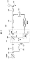
- FIG. 1 shows a single voltage transformer 303, a tap changer 302, which is a main circuit of the automatic voltage regulator 300, and a tap control device 310, which is a control device.
- the tap control device 310 includes a measuring unit 320, a line voltage drop compensation circuit (LDC) 330, an SVC output history grasping device 340, and a database 350, and taps to control the secondary side voltage of the autotransformer 303 to a predetermined value.
- the changer 302 is operated.
- the measurement unit 320 of the tap control device 310 is connected to a current sensor CT that measures the secondary current Isvr of the distribution line and a voltage sensor PT that measures the secondary voltage Vsvr.
- the line voltage drop compensation circuit (LDC) 330 detects that the secondary side voltage Vsvr measured by the measurement unit 320 deviates from a predetermined limit value, and this state continues for a predetermined measurement time or longer. Switch control is executed.
- LDC line voltage drop compensation circuit
- the present invention is not limited to this method, but can be performed as follows, for example.
- the line voltage drop compensation circuit (LDC) 330 uses the secondary side current Isvr and the secondary side voltage Vsvr measured by the measuring unit 320 to obtain the active power Psvr, the reactive power Qsvr, and the power factor. Calculate cos ⁇ .
- the line voltage drop compensation circuit (LDC) 330 reads parameters (R, X, Vref) used for executing the expression (1) from the database 350.
- the tap operation determination reference value Vs is calculated.
- Vs Vref + R ⁇ Ir + X ⁇ Ii (1)
- R, X, and Vref are preset parameters
- Ir and Ii are the real part of the passing current obtained from the measured passing current Isvr and the power factor cos ⁇ , and the imaginary part of the passing current.
- R is a coefficient for the real part Ir of the passing current of the automatic voltage regulator SVR
- X is a coefficient for the imaginary part Ii of the passing current of the automatic voltage regulator SVR
- Vref is a reference voltage.
- the secondary voltage of the automatic voltage regulator SVR varies depending on the active power Psvr or the reactive power Qsvr, but the equation (1) is calculated by using the magnitude of the variation as the reference value Vs. It can be said that the reference value Vs is calculated by calculating the voltage at the load center of gravity of the distribution line among the voltages (secondary side voltages) at the respective distribution lines on the secondary side of the automatic voltage regulator SVR.
- this value is a variable value reflecting the load status (active power fluctuation or reactive current fluctuation). Even if the tap position of the tap changer 302 of the autotransformer 303 is the same, the secondary side voltage varies depending on the active power Psvr or the reactive power Qsvr. When the secondary side voltage deviates from the range determined by equation (1), it is necessary to correct the tap position.
- the time required to satisfy the condition that the secondary voltage Vsvr of the automatic voltage regulator SVR exceeds the predetermined limit value ⁇ with respect to the reference value Vs obtained by the expression (1) is provided in the tap control device.
- the value is accumulated by a timer and the value exceeds a certain time Tsvr, a switching command is issued to the tap.
- the tap 302 of the automatic voltage regulator SVR is moved upward. Change and increase the secondary voltage.
- the tap 302 of the automatic voltage regulator SVR is changed in the downward direction, Reduce the voltage.
- FIG. 3 shows a voltage graph when the voltage is lowered by tapping.
- FIG. 3 shows time t on the horizontal axis and the secondary side voltage Vsvr on the vertical axis, and it is assumed that the secondary side voltage Vsvr increases with the passage of time. Then, it is assumed that the secondary voltage Vsvr of the automatic voltage regulator SVR exceeds the reference value plus a constant value (Vs + ⁇ ) at time t1.
- the tap controller 310 of the automatic voltage regulator SVR is in a state where the secondary side voltage Vsvr has exceeded the reference value plus a constant value (Vs + ⁇ ) even after a predetermined set time Tsvr seconds has elapsed. Confirm.
- the tap control device 310 performs a tap operation at time t2 when a predetermined set time Tsvr seconds has elapsed.
- the automatic voltage regulator SVR secondary side voltage Vsvr drops to a reference value plus a constant value (Vs + ⁇ ) or less as shown by the dotted line waveform in (b).
- the constant value ⁇ is a constant for providing a dead zone, and (a) shows a case where the tap operation is not performed.
- the line voltage drop compensation circuit (LDC) 330 is based on the passing current information of the automatic voltage regulator SVR and the parameters set in the line voltage drop compensation circuit LDC.
- the secondary side voltage Vsvr is controlled.
- the output of the reactive power compensator (SVC) 160 installed on the terminal side from the automatic voltage regulator SVR is output.
- the tap control operation is determined in consideration of the history data.
- the tap control device 310 includes a line voltage drop compensation circuit (LDC) 330, a measurement unit 320, an SVC output history grasping device 340, and a database 350.
- LDC line voltage drop compensation circuit
- the database 350 stores, as various parameters (LDC parameters), a dead zone ⁇ , a timer time constant Tsvr, and a sensitivity coefficient Xs in addition to Vref, R, and X used in equation (1).
- LDC parameters various parameters
- Tsvr timer time constant
- Xs sensitivity coefficient
- the SVC output history grasping device 340 grasps data relating to the output history of the reactive power compensator (SVC) 160 installed on the terminal side from the automatic voltage regulator SVR. For example, when the current time is t2 and the appropriate past time is t1, time series data (Isvc (t)) of the output current Isvc provided by the reactive power compensator SVC in the period from time t1 to t2 is collected.
- the time series data Isvc (t) may be received, for example, from the reactive power compensator SVC directly via the communication network.
- LDC line voltage drop compensation circuit
- the line voltage drop compensation circuit (LDC) 330 automatically adjusts the voltage during a certain period of time T in accordance with various parameters in the database 350 and the SVC output history current Isvc (t) of the SVC output history grasping device 340. It is determined whether or not the tap control of the device SVR needs to be performed, and a tap command value is obtained. When it is found that tap control needs to be performed, a tap switching command is sent to the automatic voltage regulator SVR.
- LDC line voltage drop compensation circuit
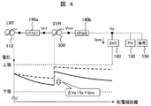
- FIG. 4 shows an example of a power distribution system in which an automatic voltage regulator SVR and a reactive power compensator SVC are installed.
- the horizontal axis indicates the distance of the distribution line (corresponding to the location of the distribution system example), and the vertical axis indicates the voltage of the distribution line.
- the reactive power compensator SVC operating with a static mechanism operates faster than the automatic voltage regulator SVR having a mechanical mechanism.
- the voltage Vc at its own end is controlled to a constant value, thereby realizing the voltage distribution of the distribution line shown by the dotted line.
- the automatic voltage regulator SVR cannot detect from its own end information (Vsvr or the like) that it is in a situation where it should operate.
- the automatic voltage regulator SVR is operated assuming that the reactive power compensator SVC has no output, the output of the reactive power compensator SVC can be reduced, which is considered to be an appropriate share of operation. .
- appropriate cooperative voltage control is possible in which the automatic voltage regulator SVR shares the long-time voltage fluctuation and the reactive power compensator SVC shares the short-time voltage fluctuation.
- the automatic voltage regulator SVR grasps the current output value or output history information of the reactive power compensator SVC, and estimates the self-end voltage value assuming that the reactive power compensator SVC has no output based on the information. Then, the tap value is determined based on the estimated self-end voltage value. For example, the voltage correction amount ⁇ Vs is calculated using the output current Isvc of the reactive power compensator SVC and the parameter Xs corresponding to the short-circuit reactance on the distribution substation side from the automatic voltage regulator SVR. calculate.
- the output current Isvc of the reactive power compensator SVC cannot be obtained continuously, for example, when information is sent from the reactive power compensator SVC at a certain time interval, the following control is performed. Just do it. First, instead of the current value, time series data (history information) Isvc after the time when the received information was received last time is received. Even in the automatic voltage regulator SVR, the self-end measurement information after the last received time is stored. When the information of the output current Isvc of the reactive power compensator SVC is received, it is calculated retroactively whether tap control of the automatic voltage regulator SVR is necessary until the time of the previous reception, and the current automatic Determine the voltage regulator SVR tap.
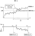
- FIG. 5 shows an image of the output current Isvc of the reactive power compensator SVC exchanged at regular intervals. All graphs show time on the horizontal axis.
- the vertical axis of the upper graph shows Vsvr of the secondary voltage of the automatic voltage regulator SVR, and the vertical axis of the lower graph shows the output Isvc of the reactive power compensator SVC.
- the actual Vsvr is indicated by a solid line
- the secondary side voltage estimated value Vsvr 'when there is no output of the reactive power compensator SVC is indicated by a dotted line.
- the reactive power compensator SVC is trying to control its own terminal voltage below the upper limit value of the distribution line, and since the upper limit is reached at time t3, the output Isvc of the reactive power compensator SVC is started to operate on the delay side.
- the secondary side voltage Vsvr of the automatic voltage regulator SVR was fixed at the upper limit.
- the situation during this time is shown as actual Vsvr by a solid line from time t3 to time t2.
- the value of Vsvr is an example in which the value is near the upper limit of the voltage of the distribution line.
- the Isvc information during the period from t1 to t2 is collectively transmitted at the time (current time) t2.
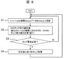
- step S1 of FIG. 6 the Isvc history data from the time t1 to the time t2 of FIG. 5 is received from the reactive power compensator SVC.
- step S2 automatic voltage regulator SVR tap command value calculation is performed. Specifically, the tap command value of the automatic voltage regulator SVR is calculated by going back to the past t1 to t2. Details of this calculation process will be described later with reference to FIG.
- step S3 if the tap of the automatic voltage regulator SVR is to be changed, the process proceeds to step S4, and if not, a determination is made to return to the beginning.
- step S4 an operation of changing the tap of the automatic voltage regulator SVR is performed based on the command value.
- the time t of the data to be processed is set to t1 (value immediately after the previous calculation of the past history).
- step S21 the SVR secondary voltage Vsvr, the passing current Isvr, the passing current power factor cos ⁇ , and the SVC output current Isvc used for the tap control at time t are read and acquired.
- step S22 the tap operation determination reference value Vs and the voltage correction amount ⁇ Vs are calculated according to equations (2), (3), and (4).
- the database 350 is referred to as appropriate for parameters used in executing these equations.
- the concept of the voltage correction amount ⁇ Vs obtained by the equation (2) is shown in FIG. 4, and this is because the terminal voltage of the automatic voltage regulator SVR indicates that the reactive power compensator SVC has no output and the output has The voltage difference generated between the cases is obtained.
- the tap operation determination reference value Vs is obtained by calculating Expression (3) that specifically represents Expression (1).
- Vs Vref + R.Isvr.cos .theta. + X.Isvr.sin .theta. (3) Since the tap operation determination reference value Vs in the equation (3) includes the voltage fluctuation due to the output of the reactive power compensator SVC, this influence is excluded by the equation (4). Thereby, the tap operation determination reference value Vs ′ assuming that there is no reactive power compensator SVC is obtained.
- Vs ′ Vs ⁇ Vs (4)
- step S23a the dead zone upper limit deviation determination is performed by equation (5).
- Vsvr> Vs ′ + ⁇ (5) If equation (5) is not satisfied, the process returns to step S21, and the above processing is repeatedly executed based on a new input at the next processing time.
- step S24a the count value of the timer ⁇ 1 is compared with the set value of the departure confirmation time Tsvr. When the count value exceeds the set time, the process proceeds to step S26a.
- step S26a the tap of the automatic voltage regulator SVR is changed in the direction in which the secondary voltage decreases.
- step S23b the lower limit deviation determination of the dead zone is performed by equation (6) [Equation 6] Vsvr ⁇ Vs′ ⁇ (6) If equation (6) is not satisfied, the process returns to step S21, and the above processing is repeatedly executed based on a new input at the next processing time.
- step S24b the count value of the timer ⁇ 2 is compared with the set value of the departure confirmation time Tsvr. When the count value exceeds the set time, the process proceeds to step S26b.
- step S26b the tap of the automatic voltage regulator SVR is changed in the direction in which the secondary side voltage increases.
- Step S27 is performed after the tap change process, and the values of the timers ⁇ 1 and ⁇ 2 are set to 0 and reset.
- step 28 when the time reaches t2 (current value), the process is terminated (proceeds to step 3 in FIG. 6). Otherwise, the process returns to step 21.
- the tap operation determination reference value Vs ′ of the automatic voltage regulator SVR is corrected to a smaller value when the output of the reactive power compensator SVC increases toward the advance side. As a result, the automatic voltage regulator SVR is operated to raise the tap (to increase the secondary voltage). Conversely, the tap operation determination reference value Vs ′ of the automatic voltage regulator SVR is corrected to a larger value when the output of the reactive power compensator SVC increases toward the delay side. As a result, the automatic voltage regulator SVR is operated to lower the tap (lower the secondary voltage).
- the fluctuation range of the output of the reactive power compensator SVC can be reduced by the influence of the tap operation of these automatic voltage regulators SVR. This means that the reactive power compensator SVC does not need to be operated to its output limit point.
- step S31 to step S35 will be described with reference to FIG. 8 regarding the operation process of the reactive power compensator SVC that sends data to the automatic voltage regulator SVR.
- step S31 the output Isvc is determined by, for example, constant voltage control according to the control logic of the reactive power compensator SVC.
- step S32 Isvc of the reactive power compensator SVC output is stored.
- step S33 it is determined whether it is a communication timing (whether ⁇ t has passed since the previous communication execution time). If so, the process returns to step S34, and otherwise, the process returns to step S31.
- step S35 the stored time series data of Isvc (t) is reset, and the process returns to step S31.
- FIG. 9 and FIG. 10 an example of the control operation of the automatic voltage regulator SVR and the reactive power compensator SVC according to the conventional method and an example of the control operation waveform according to the present invention will be shown.
- FIG. 9 shows a control operation waveform example of the reactive power output proportional to the system voltage, the automatic voltage regulator SVR tap, and the reactive power compensator SVC output current according to the conventional method.
- the voltage values of the automatic voltage regulator SVR terminal and the reactive power compensator SVC terminal with respect to the passage of time are shown.
- the transition of the movement of the tap number of the automatic voltage regulator SVR with respect to the passage of time is shown.
- the transition of the reactive power output of the reactive power compensator SVC over time is shown.
- the time on the horizontal axis is 600 seconds (10 minutes)
- the output upper limit of the reactive power compensator SVC is ⁇ 600 kvar
- the load on the distribution line increases at 200 and 400 seconds.
- the automatic voltage regulator SVR and the reactive power compensator SVC are used to control the voltage at the end of the reactive power compensator SVC from the lower limit voltage VL (6600 volts) to the upper limit voltage VU (6800 volts). It is controlled.
- the tap number of the automatic voltage regulator SVR is 4, and the reactive power output of the reactive power compensator SVC is ⁇ 150 (kvar), thereby maintaining the system voltage at 6650 volts. It was.
- the reactive power compensator SVC operates to keep the system voltage constant in response to the load increase at time 200 seconds, and the reactive power output is reduced to the lower limit of ⁇ 600 (kvar).
- the voltage could not be maintained at 6650 volts, resulting in a slight voltage drop.
- the lower limit voltage VL (6600 volts) is not reached, the automatic voltage regulator SVR does not perform tap change control.
- both the automatic voltage regulator SVR end voltage Vsvr and the reactive power compensator SVC end voltage Vsvc have voltage deviations from the lower limit voltage VL (6600 volts). It has occurred. Even when the automatic voltage regulator SVR terminal voltage Vsvr recovers to the lower limit voltage or higher in the state where the tap is switched to step 5, the reactive power compensator SVC terminal voltage Vsvc may not recover to the lower limit voltage or higher.
- FIG. 10 shows a control operation waveform example of the automatic voltage regulator SVR and the reactive power compensator SVC according to the present invention under the same conditions as FIG.
- the waveform of FIG. 10 will be described by comparing with the waveform of FIG.
- the tap number of the automatic voltage regulator SVR was 4, and the reactive power output of the reactive power compensator SVC was ⁇ 150 (kvar), thereby maintaining the system voltage at 6650 volts. Thereafter, an increase in load occurred at 200 seconds, and in response to this, the reactive power compensator SVC operated to keep the system voltage constant.
- the presupposed state up to this point is the same as the conventional case of FIG.
- the automatic voltage regulator SVR estimates the secondary voltage on the assumption that the reactive power compensator SVC is not operating. In this estimation, the secondary voltage becomes lower than the lower limit voltage VL due to the load increase occurring at time 200 seconds, and as a result, the automatic voltage regulator SVR performs a tap operation at the time when the confirmation time after time 200 seconds has elapsed. Raise from 4th to 5th level.
- the reactive power compensator SVC reduces its reactive power output to the lower limit of ⁇ 600 (kvar), but by changing the tap of the automatic voltage regulator SVR, the reactive power output is finally reduced to, for example, Stabilizes when reduced to -300 (kvar). Further, during this confirmation time period, the system voltage is maintained at the lower limit voltage VU or more by the reactive power compensator SVC being reduced to the lower limit of ⁇ 600 (kvar), and after that, there is also the influence of the tap operation. Maintained on the bolt.
- the reactive power compensator SVC When the output of the reactive power compensator SVC is -300 kvar and the tap of the automatic voltage regulator SVR is in five stages, a second load increase occurs at 400 seconds. Also at this time, the reactive power compensator SVC responds immediately and reduces its reactive power output to the lower limit of ⁇ 600 (kvar).
- the automatic voltage regulator SVR estimates the secondary voltage on the assumption that the reactive power compensator SVC is not operating. In this estimation, the secondary voltage becomes lower than the lower limit voltage VL due to the second load increase occurring at time 400 seconds, and as a result, the automatic voltage regulator SVR performs tap operation at the time when the confirmation time after time 400 seconds has elapsed. And raise from 5 to 6.
- the automatic voltage regulator SVR end voltage Vsvr has a voltage deviation.
- the reactive power compensator SVC end voltage Vsvc is also restored to the lower limit voltage VU or more.
- the voltage deviation and duration can be reduced by appropriately performing voltage control sharing by the automatic voltage regulator SVR tap operation when the reactive power compensator SVC is output. Moreover, it can be seen from this result that the voltage deviation time can be shortened even if the required capacity of the reactive power compensator SVC is small.
- It can be used as a voltage regulator that regulates the voltage of the distribution system. Moreover, it can be utilized as a control system for the SVR that is a voltage regulator or a distribution substation LRT, or a control system for the reactive power compensator SVC. Further, in the distribution system, it can be used as a voltage maintenance measure and a distribution facility utilization rate improvement measure corresponding to the addition of a distributed power source such as solar power generation.
- Distribution system 110 Distribution substation 120: Node 130: Solar power generator 140: Distribution line 150: Load 160: SVC 170: Sensor 300: SVR 302: Tap changer 303 : Auto-transformer, 305: Transformer, 310: Tap control device, CT: Current sensor, PT: Voltage sensor, 320: Measuring unit of control device, 330: LDC, 340: SVC output history grasping device, 350: Database
Landscapes
- Engineering & Computer Science (AREA)
- Power Engineering (AREA)
- Physics & Mathematics (AREA)
- Electromagnetism (AREA)
- General Physics & Mathematics (AREA)
- Radar, Positioning & Navigation (AREA)
- Automation & Control Theory (AREA)
- Supply And Distribution Of Alternating Current (AREA)
- Control Of Electrical Variables (AREA)
Description
本発明は、配電系統の電圧調整装置、電圧調整方法および電力制御システムに係り、特に配電系統の電圧変動に対応し、電圧調整装置と無効電力補償装置を協調して適切に動作させ、電圧維持や運用効率化を可能とする配電系統の電圧調整装置、電圧調整方法および電力制御システムに関する。
配電系統の電圧は、配電用変電所に設置された変圧器(負荷時タップ切替変圧器LRT:Load Ratio Control Transformer)のタップ切替や、配電線上に設置された自動電圧調整器(SVR:Step Voltage Regulator)などのタップ切替によって制御される。これらの負荷時タップ切替変圧器LRTや自動電圧調整器SVRは、機械機構(タップ)により電圧調整を行うものであり、以後これらを総称して電圧調整装置SVRということにする。
これらの電圧調整装置SVRは、タップの切替までに一般的に数十秒の応答時定数で動作するように設定されている。また複数の電圧調整装置が配電線路に直列に設置される場合、配電線路(フィーダ)の末端側に設置される電圧調整装置は、変電所側(送出し側)に設置される電圧調整装置よりも応答時定数を遅く設定するのが一般的である。これにより、末端側の電圧調整装置の不要な動作を少なくしている。
ところで、近年の配電系統では太陽光発電装置を備えた需要家が増大している。この場合に、太陽光発電装置の発電出力は天候変動に左右され配電系統の急激な電圧変動を生じさせる原因となっている。
これに対し、高速な無効電力出力制御によって電圧変動を抑制する機能を持つ無効電力補償装置SVC(Static Var Compensator)、あるいはSTATCOM(Static synchronous Compensator)を配電系統に接続することによって、急激な電圧変動の抑制が期待されている。これらの無効電力補償装置SVCやSTATCOMは、静止機構(IGBTなど)により無効電力補償を行うものであり、以後これらを総称して無効電力補償装置SVCということにする。
配電系統に電圧調整装置SVRおよび無効電力補償装置SVCを設置する場合、機械機構を備える電圧調整装置SVRが変電所側(送出し側)に設置され、静止機構で作動する無効電力補償装置SVCが配電線路(フィーダ)の末端側に設置されることになる。このことは、フィーダ末端ほど応答時定数を遅く設定するという従来の時間協調制御の考えに反することになる。
このため、配電系統に電圧調整装置SVRと無効電力補償装置SVCを同時に設置する場合、電圧変動に対して、無効電力補償装置SVCが電圧調整装置SVRよりも先に動作し、定常的な電圧変動も無効電力補償装置SVCが抑制することで、電圧調整装置SVRが動作しない現象が発生することが懸念されている。
このような場合、無効電力補償装置SVCは最大出力で運転し続けることになり、急峻な電圧変動を抑制するための出力の余裕がなくなってしまい、結果として急峻な電圧変動を抑制できなくなる場合が発生する。つまり無効電力補償装置SVCの本来の設置目的であった、太陽光発電出力の急変に対する電圧変動抑制の機能が、本来実行すべき天候急変時に果たせなくなる恐れがある。
然るに、電圧調整装置SVRと無効電力補償装置SVCを同時に設置する場合は、双方が適切に電圧変動抑制制御を行うことが重要となる。
電圧調整装置SVRと無効電力補償装置SVCを協調して動作させる制御方法として、次のような手法が示されている。例えば、特許文献1には、最適電圧調整装置において電圧調整装置SVRと無効電力補償装置SVCの制御量を、最適化問題を解くことで決定して各機器の制御指令値とする方法が示されている。
また、特許文献2には、無効電力補償装置SVCの無効電力出力を時間とともに減じていくことで電圧調整装置SVRに制御分担を移す方法が示されている。
前述の特許文献1に記載の方法では、無効電力補償装置SVCと電圧調整装置SVRの制御量を決定するために系統の潮流計算が可能な情報を集める必要がある。そのために系統状態を把握するセンサや伝送ネットワークの設置や、最適電圧調整装置を用意する必要がある。また、データ収集、最適計算周期よりも早い制御が困難となり、急激な電圧変動に対する動作追従遅れが生じ、電圧逸脱時間の増大につながる問題がある。
また、特許文献2に記載の方法では、無効電力補償装置SVCの出力を一旦減少させるために、電圧目標値に対し制御誤差が発生する課題がある。
以上のことから本発明は、電圧調整装置と無効電力補償装置を協調して適切に動作させ、電圧維持や運用効率化を可能とする配電系統の電圧調整装置、電圧調整方法および電力制御システムを提供するものである。
以上のことから本発明においては、末端側に無効電力補償装置を備えた配電系統に設置され、タップ位置を調整して二次側電圧を所定の制限値内に調整する配電系統の電圧調整装置において、
二次側電圧を推定する第1の手段、推定した二次側電圧を無効電力補償装置の出力から求めた補正分により補正した補正電圧を得る第2の手段、補正電圧と所定の制限値を比較し、補正電圧が所定の制限値を逸脱するときにタップ位置の操作を実行する第3の手段を備える。
二次側電圧を推定する第1の手段、推定した二次側電圧を無効電力補償装置の出力から求めた補正分により補正した補正電圧を得る第2の手段、補正電圧と所定の制限値を比較し、補正電圧が所定の制限値を逸脱するときにタップ位置の操作を実行する第3の手段を備える。
また第2の手段の補正電圧は、無効電力補償装置の出力が進み側に増大する時により小さな値に補正修正され、無効電力補償装置の出力が遅れ側に増大する時により大きな値に修正される。
また第3の手段のタップ位置の操作は、無効電力補償装置の出力が進み側に増大する時に二次側電圧を上げる方向のタップ位置となり、無効電力補償装置の出力が遅れ側に増大する時に二次側電圧を下げる方向のタップ位置とされる。
また第2の手段の補正電圧は、無効電力補償装置の出力がないときの二次側電圧を求めたものである。
本発明の配電系統の電圧調整装置、電圧調整方法および電力制御システムにより、太陽光発電装置などが大量に導入された系統でも、配電系統の電圧逸脱の可能性を小さくでき、また早い周期の電圧変動を抑制するために必要となる無効電力補償装置SVCなどの高速応答可能な電圧制御機器の必要容量を削減できる効果がある。
また、本発明のそれ以外の効果については、明細書中で説明する
以下、本発明の実施例について図面を用いて説明する。
図2は、電圧調整装置300(負荷時タップ切替変圧器LRTや自動電圧調整器SVR)および無効電力補償装置160(SVCやSTATCOM)が設置された配電系統100(フィーダ)の一例を示した図である。但しここでは、電圧調整装置300として自動電圧調整器SVRを配置した例を示しているが、これは負荷時タップ切替変圧器LRTとしてもよい。
この図で示される典型的な配電系統100は、ノード(母線)120およびそれらを接続する配電線路140、ノード120に接続される負荷150や太陽光発電装置130、配電線路に設置されるセンサ170、配電用変電所110などで構成される。
ここで、配電用変電所110のある図示左側をフィーダの送出し側、右側をフィーダの末端側と呼ぶこととする。自動電圧調整器300は、線路140に直列に設置され、線路電圧を調整する電圧調整装置である。
自動電圧調整器SVRは、配電用変電所110における負荷時タップ切替変圧器LRTであってもよいが、例えば自動電圧調整器300に例示されるように、単巻変圧器とタップチェンジャで構成される変圧器305と、制御部分を備える。
図2の自動電圧調整器SVRの制御部分は、配電線路の電気量を測定するセンサ170、変圧器のタップを制御するタップ制御装置310で構成される。本発明に係る変圧器305と、制御部分の具体的な回路構成例を図1に示す。
図1において、本発明では従来からのタップ制御装置310にSVC出力履歴把握装置340を追加し、無効電力補償装置SVCの出力履歴の情報を元に、線路電圧降下補償回路(LDC)330によってタップ値を制御する。ここで、線路電圧降下補償装置LDC(Line Drop Compensator)は、系統の電圧低下を補償するように負荷時タップ切替変圧器LRTや、自動電圧調整器SVRの二次側電圧を決定する制御装置である。本発明の線路電圧降下補償回路(LDC)330は、タップ制御装置310とSVC出力履歴把握装置340の情報を元に作動する。
図1を用いてまず従来のタップ制御の考え方を説明し、その後に本発明により追加されたSVC出力履歴把握装置340との関わりについて説明する。図1には、自動電圧調整器300の主回路である単巻変圧器303、タップチェンジャ302と、制御装置であるタップ制御装置310が記載されている。
タップ制御装置310は、計測部320、線路電圧降下補償回路(LDC)330、SVC出力履歴把握装置340、データベース350を備え、単巻変圧器303の二次側電圧を所定値に制御すべくタップチェンジャ302を操作している。
タップ制御装置310の計測部320には、配電線路の二次側電流Isvrを測定する電流センサCT、および二次側電圧Vsvrを測定する電圧センサPTが接続される。
線路電圧降下補償回路(LDC)330では、計測部320で測定された二次側電圧Vsvrが、所定の制限値を逸脱していることを検出し、この状態が所定の計測時間以上継続していることをもって、切替制御を実行する。
タップ制御装置310における上記の切替制御については、従来から種々の方式が提案されている。本発明ではこの方式に限定されるものではないが、例えば以下のように行うことができる。
タップ切替の典型的な一例では、線路電圧降下補償回路(LDC)330は、計測部320で測定された二次側電流Isvr、二次側電圧Vsvrから、有効電力Psvr、無効電力Qsvr、力率cosθを計算する。
また線路電圧降下補償回路(LDC)330は、データベース350から(1)式の実行に使用するパラメータ(R、X、Vref)を読み込む。タップ制御装置310における(1)式の実行により、タップ動作判定基準値Vsが計算される。
[数1]
Vs=Vref+R・Ir+X・Ii (1)
ここで、R、X、Vrefは、予め設定されたパラメータであり、IrとIiは、計測した通過電流Isvrと力率cosθから求めた通過電流の実部と、通過電流の虚部である。そして、Rは自動電圧調整器SVRの通過電流の実部Irに対する係数、Xは自動電圧調整器SVRの通過電流の虚部Iiに対する係数、Vrefは基準電圧である。
[数1]
Vs=Vref+R・Ir+X・Ii (1)
ここで、R、X、Vrefは、予め設定されたパラメータであり、IrとIiは、計測した通過電流Isvrと力率cosθから求めた通過電流の実部と、通過電流の虚部である。そして、Rは自動電圧調整器SVRの通過電流の実部Irに対する係数、Xは自動電圧調整器SVRの通過電流の虚部Iiに対する係数、Vrefは基準電圧である。
自動電圧調整器SVRの二次側電圧は、有効電力Psvrあるいは無効電力Qsvrによって変動するが、(1)式はその変動の大きさを基準値Vsとして計算したものである。基準値Vsは、自動電圧調整器SVRの二次側の配電線路各所における電圧(二次側電圧)のうち、当該配電線路の負荷重心点の電圧を算出したものということができる。
またこの値は負荷状況(有効電力変動、あるいは無効電流変動)を反映した可変の値である。二次側電圧は、単巻変圧器303のタップチェンジャ302のタップ位置が同じであっても、有効電力Psvrあるいは無効電力Qsvrによって変動する。二次側電圧が(1)式で定まる範囲を逸脱するときには、タップ位置を修正する必要がある。
このため、(1)式で求めた基準値Vsに対して自動電圧調整器SVRの二次側電圧Vsvrが、所定の制限値εを超えるという条件を満たす時間をタップ制御装置内に設けられたタイマで積算し、その値が一定時間Tsvrを超えた場合にタップへ切換え指令が出される。
例えば、自動電圧調整器SVRの二次側電圧Vsvrが、この基準値Vsより一定値ε以上小さい状態で一定時間(例えば、Tsvr秒)経過すると、自動電圧調整器SVRのタップ302を上げ方向に変更し、二次側電圧を上昇させる。逆に、自動電圧調整器SVRの二次側電圧Vsvrがこの基準値Vsより一定値ε以上大きい状態で一定時間経過すると、自動電圧調整器SVRのタップ302を下げ方向に変更し、二次側電圧を下降させる。
図3に、タップによって電圧を下げる場合の電圧経過グラフを示す。図3は横軸に時間t、縦軸に二次側電圧Vsvrを示しており、二次側電圧Vsvrが時間の経過と共に増加していったとする。そして、時刻t1で自動電圧調整器SVRの二次側電圧Vsvrが基準値プラス一定値(Vs+ε)を超えたとする。
この場合に、自動電圧調整器SVRのタップ制御装置310は、所定の設定時間Tsvr秒経過しても二次側電圧Vsvrが基準値プラス一定値(Vs+ε)を超えた状態が継続していることを確認する。タップ制御装置310は、所定の設定時間Tsvr秒経過した時刻t2においてタップ動作させる。
これにより、(b)の点線波形のように自動電圧調整器SVR二次側電圧Vsvrは、基準値プラス一定値(Vs+ε)以下まで下降する。ここで、一定値εは不感帯を設けるための定数であり、(a)は、タップ動作させない場合を示している。
このように、タップ制御装置310における従来知られた一例では、線路電圧降下補償回路(LDC)330は、自動電圧調整器SVRの通過電流情報と線路電圧降下補償回路LDCに設定されたパラメータを元に、二次側電圧Vsvrの制御を行う。
これに対し本発明では、通常の自動電圧調整器SVRのタップ制御装置のタップ動作判定基準値Vs以外に、自動電圧調整器SVRより末端側に設置された無効電力補償装置(SVC)160の出力履歴データを勘案して、タップ制御動作の判定を行う。
図1に示すように、タップ制御装置310は、線路電圧降下補償回路(LDC)330、計測部320、SVC出力履歴把握装置340、データベース350で構成される。
データベース350には、各種パラメータ(LDCパラメータ)として、(1)式で用いるVref、R、X以外に、不感帯ε、タイマ時定数Tsvr、感度係数Xs、が記憶されている。
このうち本発明により追加されたSVC出力履歴把握装置340は、自動電圧調整器SVRより末端側に設置された無効電力補償装置(SVC)160の出力履歴に関するデータを把握する。例えば、現時点を時刻t2、適宜の過去時刻をt1とすると、時刻t1からt2までの期間に無効電力補償装置SVCが与えた出力電流Isvcの時系列データ(Isvc(t))を収集する。時系列データIsvc(t)は、例えば無効電力補償装置SVCから直接通信網を介して受け取ればよい。
また、SVC出力履歴把握装置340は、一定期間毎に(例えば、時刻T(=t2-t1)毎に)時系列データIsvc(t)を受け取り、線路電圧降下補償回路(LDC)330にタップ計算指令開始を指示する。
線路電圧降下補償回路(LDC)330は、データベース350内の各種パラメータと、SVC出力履歴把握装置340のSVC出力履歴電流Isvc(t)に応じて、過去の一定期間T時間の間に自動電圧調整器SVRのタップ制御を行う必要があったか、動作判定を行い、タップ指令値を求める。タップ制御を行う必要があることが分かった場合、自動電圧調整器SVRにタップ切換指令を送る。
以下本発明装置の動作説明に入る前に、自動電圧調整器SVRのタップ制御動作に無効電力補償装置SVCの出力を考慮して、協調動作させるときの考え方について、図4と図5により説明しておく。
図4は自動電圧調整器SVRと無効電力補償装置SVCが設置された配電系統の例を示している。また図4の下部に示すグラフは、横軸に配電線の距離(配電系統の例の場所に対応)を、縦軸に配電線の電圧を示している。
ここでは、無効電力補償装置SVCが自端の電圧Vcを一定値に制御するように出力している状況の電圧分布を点線で、無効電力補償装置SVCが出力なしの場合(出力Isvc=0の場合)の電圧分布を実線で、模式的に示している。
先にも述べたように、静止機構で作動する無効電力補償装置SVCは、機械機構を有する自動電圧調整器SVRより高速に動作する。そして無効電力補償装置SVCが機能している状態では、自端の電圧Vcを一定値に制御し、点線で示す配電線路の電圧分布を実現している。この状態では線路状態が一定に保持されるので、自動電圧調整器SVRは自端情報(Vsvrなど)から自己が動作すべき状況にあることを検知することができない。
これに対し、自動電圧調整器SVRは、無効電力補償装置SVCが出力なしの場合を想定して動作すれば、無効電力補償装置SVCの出力を少なくできることになり、適切な動作分担となると考えられる。言い換えると、長時間の電圧変動を自動電圧調整器SVRが分担し、短時間の電圧変動を無効電力補償装置SVCが分担するような、適切な協調電圧制御が可能となると言える。
このような制御を実現するためには、無効電力補償装置SVCが出力なしの場合の自動電圧調整器SVRの自端情報がわかればよい。具体的には例えば、無効電力補償装置SVCの出力あり、なしの場合の、自動電圧調整器SVR自端情報の電圧の差分である、ΔVsがわかれば、自端の電圧計測値VsvrからΔVsを減じることで、無効電力補償装置SVC出力なしの場合を想定した自動電圧調整器SVRのタップ制御が可能となる。
本発明の基本概念においては以下のように操作することを提案する。自動電圧調整器SVRは、無効電力補償装置SVCの出力現在値または出力履歴情報を把握し、その情報を元に無効電力補償装置SVCが出力なしの場合を想定した自端の電圧値を推定し、推定した自端の電圧値を元にタップ値を決定する。自端の電圧値の推定には、例えば無効電力補償装置SVCの出力電流Isvcと、自動電圧調整器SVRから配電用変電所側の短絡リアクタンスに相当するパラメータXsを用いて、電圧補正量ΔVsを計算する。
ここで、無効電力補償装置SVCの出力電流Isvcが、例えば無効電力補償装置SVCからある時間間隔をおいて情報が送られてくるなど、連続的に得られない場合は、次のような制御を行えばよい。まず、現在値の代わりに、受け取る情報を前回受け取った時間以降の、時系列データ(履歴情報)Isvcを受け取る。自動電圧調整器SVRでも、前回受けとった時刻以降の自端計測情報を保存しておく。無効電力補償装置SVCの出力電流Isvcの情報を受け取った時点で、前回受け取った時刻まで自動電圧調整器SVRのタップ制御が必要であったかどうかをさかのぼって計算し、その結果をもとに現在の自動電圧調整器SVRタップを決定する。
図5に一定期間毎にやり取りする無効電力補償装置SVCの出力電流Isvcのイメージを示す。グラフはいずれも横軸に時刻を表す。上のグラフの縦軸は自動電圧調整器SVR二次側電圧のVsvrを、下のグラフの縦軸は無効電力補償装置SVCの出力Isvcを示す。上のグラフは、実際のVsvrを実線で、無効電力補償装置SVCの出力がない場合の二次側電圧推定値Vsvr’を点線で示す。
このグラフの事例によれば、時刻t3付近まで無効電力補償装置SVCの出力がない(Isvc=0)状態が継続し、この間自動電圧調整器SVRの二次側電圧Vsvrは変動を繰り返しながら電圧増加していったとする。
ところで無効電力補償装置SVCは自端電圧を配電線の上限値以下に制御しようとしており、時刻t3で上限に達したことから無効電力補償装置SVCの出力Isvcを遅れ側に操作開始した。この結果、自動電圧調整器SVRの二次側電圧Vsvrは上限に固定された。この間の様子が時刻t3から時刻t2に実線で実際のVsvrとして示されている。このように、ここでは無効電力補償装置SVCが出力している場合には、Vsvrの値は、配電線の電圧の上限近くの値となっている例を示している。
これに対し無効電力補償装置SVCが出力なしの場合を想定すると、自動電圧調整器SVR二次側電圧Vsvr’は、点線のように電圧上限を超えた値として計測されるであろうことが推定される。この推定される時系列データから、自動電圧調整器SVRのタップ値はどのような値であるべきであったかが、過去にさかのぼって計算することが可能となる。
なお、無効電力補償装置SVCから自動電圧調整器SVRへのデータ伝送は、現時点をt2とすると、t1~t2の期間のIsvc情報がまとめてt2の時刻(現時点)に伝送される。
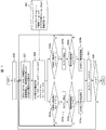
以上の考えに基づく自動電圧調整器SVRのタップ切換え処理フローを、図6に示し、以下、ステップS1~ステップS4までの各ステップの処理概要を説明する。
図6のステップS1では、図5の時刻t1から時刻t2の期間のIsvc履歴データを無効電力補償装置SVCより受け取る。
ステップS2では、自動電圧調整器SVRタップ指令値計算を行う。具体的には、過去のt1~t2の期間にさかのぼり、自動電圧調整器SVRのタップ指令値を計算する。この計算処理の詳細を、図7を用いて後ほど説明する。
ステップS3では、自動電圧調整器SVRのタップを変更すべきであればステップS4へ進み、そうでなければ、最初に戻る判定を行う。
ステップS4では、指令値に基づき自動電圧調整器SVRのタップを変更する操作を行う。
次に、図6のステップS2の、自動電圧調整器SVRタップ指令値計算処理について、図7を用いてステップS20~ステップS28までの各ステップの処理概要を詳細に説明する。
最初のステップS20では、処理対象とするデータの時刻tをt1(過去の履歴の前回計算直後の値)に設定する。
ステップS21では、時刻tにおけるタップ制御に使用するSVR二次側電圧Vsvr、通過電流Isvr、通過電流力率cosθ、SVC出力電流Isvcを読み込み、取得する。
ステップS22では、タップ動作判定基準値Vs、電圧補正量ΔVsを、(2)、(3)、(4)式に従って計算する。なおこれらの式の実行に当たって使用するパラメータなどは適宜データベース350を参照する。
[数2]
ΔVs=Xs×Isvc (2)
(2)式で求めた電圧補正量ΔVsの概念を図4に図示しているが、これは自動電圧調整器SVRの端子電圧が、無効電力補償装置SVCが出力なしの場合と、出力ありの場合とで生じる電圧差分を求めたものである。
[数2]
ΔVs=Xs×Isvc (2)
(2)式で求めた電圧補正量ΔVsの概念を図4に図示しているが、これは自動電圧調整器SVRの端子電圧が、無効電力補償装置SVCが出力なしの場合と、出力ありの場合とで生じる電圧差分を求めたものである。
タップ動作判定基準値Vsは、(1)式を具体的にあらわした(3)式を演算して求められる。
[数3]
Vs=Vref+R・Isvr・cosθ+X・Isvr・sinθ(3)
(3)式のタップ動作判定基準値Vsは無効電力補償装置SVCの出力による電圧変動分を含んでいるので、(4)式によりこの影響分を除外する。これにより、無効電力補償装置SVCがないことを想定したタップ動作判定基準値Vs’が求められる。
[数4]
Vs’=Vs-ΔVs (4)
次のステップS23では、電圧変化量が不感帯の上下限値を逸脱していることを判定する。図7の右側の列では下限値側の逸脱を、左側の列では上限値側の逸脱を判定する。このうち、ステップS23aでは、不感帯の上限逸脱判定を(5)式によって行う。
[数5]
Vsvr>Vs’+ε (5)
なお、(5)式が満たされなければステップS21に戻り、次の処理時刻の新たな入力をもとに上記処理を繰り返し実行する。
[数3]
Vs=Vref+R・Isvr・cosθ+X・Isvr・sinθ(3)
(3)式のタップ動作判定基準値Vsは無効電力補償装置SVCの出力による電圧変動分を含んでいるので、(4)式によりこの影響分を除外する。これにより、無効電力補償装置SVCがないことを想定したタップ動作判定基準値Vs’が求められる。
[数4]
Vs’=Vs-ΔVs (4)
次のステップS23では、電圧変化量が不感帯の上下限値を逸脱していることを判定する。図7の右側の列では下限値側の逸脱を、左側の列では上限値側の逸脱を判定する。このうち、ステップS23aでは、不感帯の上限逸脱判定を(5)式によって行う。
[数5]
Vsvr>Vs’+ε (5)
なお、(5)式が満たされなければステップS21に戻り、次の処理時刻の新たな入力をもとに上記処理を繰り返し実行する。
(5)式が成立(不感帯の上限逸脱)するときには、ステップS24aへ移り、タイマτ1のカウントを増やす。続いてステップS25aでは、タイマτ1のカウント値を逸脱確認時間Tsvrの設定値と比較する。カウント値が設定時間を超過しているとき、ステップS26aへ移る。
ステップS26aでは、自動電圧調整器SVRのタップを、二次側電圧が下がる方向へ変更する。
他方、ステップS23bでは不感帯の下限逸脱判定を式(6)によって行う
[数6]
Vsvr<Vs’-ε (6)
なお、(6)式が満たされなければステップS21に戻り、次の処理時刻の新たな入力をもとに上記処理を繰り返し実行する。
[数6]
Vsvr<Vs’-ε (6)
なお、(6)式が満たされなければステップS21に戻り、次の処理時刻の新たな入力をもとに上記処理を繰り返し実行する。
(6)式が成立(不感帯の下限逸脱)するときには、ステップS24bへ移り、タイマτ2のカウントを増やす。続いてステップS25bでは、タイマτ2のカウント値を逸脱確認時間Tsvrの設定値と比較する。カウント値が設定時間を超過しているとき、ステップS26bへ移る。
ステップS26bでは、自動電圧調整器SVRのタップを、二次側電圧が上がる方向へ変更する。
ステップS27は、タップ変更処理後に行われ、タイマτ1およびτ2の値を0に設定し、リセットする。
ステップ28では、時刻がt2(現在値)に至ったら終了とし(図6のステップ3へ移り)、そうでなければステップ21へ戻る。
以上の一連の処理を通じて自動電圧調整器SVRのタップ動作判定基準値Vs’は、無効電力補償装置SVCの出力が進み側に増大する時により小さな値に修正される。この結果、自動電圧調整器SVRのタップを上げるように(二次電圧を高くするように)操作することになる。逆に、自動電圧調整器SVRのタップ動作判定基準値Vs’は、無効電力補償装置SVCの出力が遅れ側に増大する時により大きな値に修正される。この結果、自動電圧調整器SVRのタップを下げるように(二次電圧を低くするように)操作することになる。
さらにこれらの自動電圧調整器SVRのタップ操作の影響により、無効電力補償装置SVCの出力の変動幅を小さくすることができる。このことは、無効電力補償装置SVCがその出力限界点まで運転する必要がないことを意味する。
次に自動電圧調整器SVRにデータを送る無効電力補償装置SVCの動作処理について図8を用いてステップS31~ステップS35までの各ステップの処理概要を説明する。
ステップS31では、無効電力補償装置SVCの制御ロジックに従って、例えば電圧一定制御によって出力Isvcを決定する。
ステップS32では、無効電力補償装置SVC出力のIsvcを記憶する。
ステップS33では、通信タイミングであるか(前回の通信実施時刻からΔtほど経過したか)を判定し、そうであれば、ステップS34へ、それ以外はステップS31へ戻る。
ステップS34では、通信間隔における対象期間(t=t1~t2)のIsvcを、SVRに送信する。
ステップS35では、記憶しているIsvc(t)の時系列データをリセットし、ステップS31へ戻る。
次に図9および図10を用いて、従来手法による自動電圧調整器SVRおよび無効電力補償装置SVCの制御動作例と、本発明による制御動作波形例を示す。
図9は従来手法による系統電圧、自動電圧調整器SVRタップ、無効電力補償装置SVC出力電流に比例する無効電力出力の制御動作波形例を示す。同図上は時間経過に対する自動電圧調整器SVR端および無効電力補償装置SVC端の電圧値を、同図中は時間経過に対する自動電圧調整器SVRのタップ番号の移動の変遷を、同図下は時間経過に対する無効電力補償装置SVCの無効電力出力の変遷を示す。
本事例では、横軸の時間経過として600秒間(10分)の期間、無効電力補償装置SVCの出力上限を±600kvarとし、配電線の負荷が200秒および400秒の時点で増加するケースを示している。またこの操作事例では、無効電力補償装置SVC端の電圧を、下限電圧VL(6600ボルト)から、上限電圧VU(6800ボルト)の範囲に制御すべく自動電圧調整器SVRおよび無効電力補償装置SVCが制御されている。
この事例では時刻0からの200秒間は、自動電圧調整器SVRのタップ番号が4、無効電力補償装置SVCの無効電力出力が-150(kvar)であり、これにより系統電圧が6650ボルトに保持されていた。
これに対し、時刻200秒での負荷増加に対応して無効電力補償装置SVCが系統電圧一定を保持すべく作動し、その無効電力出力を下限の-600(kvar)まで低減させたが、直前の6650ボルトには保持できず、若干の電圧低下を生じた。但し、下限電圧VL(6600ボルト)には達しないので、自動電圧調整器SVRはタップ変更制御を行わない。
この状態は、無効電力補償装置SVCの出力は下限の-600kvarに達しているが、自動電圧調整器SVRのタップは変更されていない状態である。ここからさらに時刻400秒において2回目の負荷増加が生じるが、無効電力補償装置SVCはこれに対応することができない。このため、系統電圧は下限電圧VL(6600ボルト)以下となり、自動電圧調整器SVRでは、その継続時間の監視に入る。
このため、自動電圧調整器SVRのタップが段階5に切り替わる確認時間の間、自動電圧調整器SVR端電圧Vsvrおよび無効電力補償装置SVC端電圧Vsvcともに、下限電圧VL(6600ボルト)に対する電圧逸脱が発生している。なお、タップが段階5に切り替わった状態で、自動電圧調整器SVR端電圧Vsvrは下限電圧以上に回復しても、無効電力補償装置SVC端電圧Vsvcは下限電圧以上に回復できないこともある。
図10は、図9と同じ条件下での本発明による自動電圧調整器SVRおよび無効電力補償装置SVCの制御動作波形例を示す。図10の波形を図9の波形と比較しながら説明する。
時刻0からの200秒間は、自動電圧調整器SVRのタップ番号が4、無効電力補償装置SVCの無効電力出力が-150(kvar)であり、これにより系統電圧が6650ボルトに保持されていた。このあと、時刻200秒で負荷増加が発生し、これに対応して無効電力補償装置SVCが系統電圧一定を保持すべく作動した。ここまでの、前提とする状態は図9の従来事例と同じである。
本発明の場合には、以後の操作において自動電圧調整器SVRは、無効電力補償装置SVCが作動していないという想定のもとに二次電圧を推定している。この推定では、時刻200秒に発生した負荷増加により、二次電圧が下限電圧VL以下となり、その結果時刻200秒以後の確認時間が経過した時刻で、自動電圧調整器SVRはタップ操作を行い、4段階から5段階に引き上げる。
この確認時間の期間中、無効電力補償装置SVCは、その無効電力出力を下限の-600(kvar)まで低減させるが、自動電圧調整器SVRのタップ変更により、最終的には無効電力出力を例えば-300(kvar)まで低減させたところで安定化する。またこの確認時間の期間中、系統電圧は無効電力補償装置SVCが下限の-600(kvar)まで低減させたことで、下限電圧VU以上に保持され、その後はタップ操作の影響もあり、例えば6700ボルトに維持されている。
無効電力補償装置SVCの出力が-300kvar、自動電圧調整器SVRのタップが5段階の状態で、さらに時刻400秒において2回目の負荷増加が生じる。このときも、無効電力補償装置SVCは即座に対応してその無効電力出力を下限の-600(kvar)まで低減させる。
またこのときも自動電圧調整器SVRは、無効電力補償装置SVCが作動していないという想定のもとに二次電圧を推定している。この推定では、時刻400秒に発生した2回目の負荷増加により、二次電圧が下限電圧VL以下となり、その結果時刻400秒以後の確認時間が経過した時刻で、自動電圧調整器SVRはタップ操作を行い、5段階から6段階に引き上げる。
自動電圧調整器SVRのタップが段階6に切り替わる確認時間の間、自動電圧調整器SVR端電圧Vsvrは、電圧逸脱が発生している。しかし、タップが段階6に切り替わった状態では、無効電力補償装置SVC端電圧Vsvcも下限電圧VU以上に回復している。
このように、無効電力補償装置SVC出力時に、自動電圧調整器SVRタップ動作によって電圧制御分担を適切におこなうことで、電圧逸脱の大きさと継続時間を縮小することが可能となることが伺える。また、この結果より、無効電力補償装置SVCの必要容量が小さくても電圧逸脱時間を短縮できる効果があることが伺える。
本発明による以上のような制御により、電圧逸脱の可能性を小さくでき、また早い周期の電圧変動を抑制するために必要となる他の高速応答可能な電圧制御機器の必要容量を削減できる効果がある。
また、無効電力補償装置SVCの出力履歴を、間隔をおいてまとめて自動電圧調整器SVRで取得することで、通信網の伝送容量や通信間隔などの性能が低い場合でも、協調制御が可能となり、通信設備コストや必要な通信帯域を削減できる効果がある。
以上のように、無効電力補償装置SVCの状態に応じて、自動電圧調整器SVRのタップ変更制御を行うことで、電圧維持を効率的に行うこと可能となる。
配電系統の電圧を調整する電圧調整装置として活用することができる。また、電圧調整装置であるSVRや配電用変電所LRTの制御システムや無効電力補償装置SVCの制御システムとして活用することがきる。また、配電系統において、太陽光発電などの分散電源の増設に対応した、電圧維持対策、配電設備利用率向上対策として活用することが可能となる。
100:配電系統,110:配電用変電所,120:ノード,130:太陽光発電装置,140:配電線路,150:負荷,160:SVC,170:センサ,300:SVR,302:タップチェンジャ,303:単巻変圧器,305:変圧器,310:タップ制御装置,CT:電流センサ,PT:電圧センサ,320:制御装置の計測部,330:LDC,340:SVC出力履歴把握装置,350:データベース
Claims (11)
- 末端側に無効電力補償装置を備えた配電系統に設置され、タップ位置を調整して二次側電圧を所定の制限値内に調整する配電系統の電圧調整装置において、
前記二次側電圧を推定する第1の手段、推定した二次側電圧を前記無効電力補償装置の出力から求めた補正分により補正した補正電圧を得る第2の手段、前記補正電圧と前記所定の制限値を比較し、前記補正電圧が前記所定の制限値を逸脱するときに前記タップ位置の操作を実行する第3の手段を備えることを特徴とする配電系統の電圧調整装置。 - 請求項1に記載の配電系統の電圧調整装置において、
前記第2の手段の補正電圧は、前記無効電力補償装置の出力が進み側に増大する時により小さな値に補正修正され、前記無効電力補償装置の出力が遅れ側に増大する時により大きな値に修正されることを特徴とする配電系統の電圧調整装置。 - 請求項1に記載の配電系統の電圧調整装置において、
前記第3の手段のタップ位置の操作は、前記無効電力補償装置の出力が進み側に増大する時に前記二次側電圧を上げる方向のタップ位置となり、無効電力補償装置の出力が遅れ側に増大する時に前記二次側電圧を下げる方向のタップ位置とされることを特徴とする配電系統の電圧調整装置。 - 請求項1に記載の配電系統の電圧調整装置において、
前記第2の手段の補正電圧は、前記無効電力補償装置の出力がないときの前記二次側電圧を求めたものであることを特徴とする配電系統の電圧調整装置。 - 請求項1に記載の配電系統の電圧調整装置において、
前記第2の手段は、前記推定した二次側電圧に前記無効電力補償装置の出力から求めた第1の補正分を加算した補正電圧を求め、前記第3の手段は、前記第1の補正電圧が所定の上限値以上の期間が所定時間以上継続することをもって前記タップ付変圧器のタップ下げ操作を実行し、また補正電圧が所定の下限値以下の期間が所定時間以上継続することをもって前記タップ付変圧器のタップ上げ操作を実行することを特徴とする配電系統の電圧調整装置。 - 請求項1に記載の配電系統の電圧調整装置において、無効電力補償装置の出力履歴データを受け取り、過去の一定期間内のタップ指令値を求めることを特徴とする配電系統の電圧調整装置。
- 配電系統末端側に備えた無効電力補償装置により電圧制御を行うとともに、配電系統上流側に備えた電圧調整装置のタップ位置調整により電圧制御を行う配電系統の電圧調整方法において、
前記電圧調整装置のタップ位置調整は、前記二次側電圧を推定し、推定した二次側電圧を前記無効電力補償装置の出力から求めた補正分により補正した補正電圧を得、前記補正電圧と所定の制限値を比較し、前記補正電圧が前記所定の制限値を逸脱するときに前記タップ位置の操作を実行することを特徴とする配電系統の電圧調整方法。 - 請求項7に記載の配電系統の電圧調整方法において、
前記補正電圧は、前記無効電力補償装置の出力が進み側に増大する時により小さな値に補正修正され、前記無効電力補償装置の出力が遅れ側に増大する時により大きな値に修正されることを特徴とする配電系統の電圧調整方法。 - 請求項7に記載の配電系統の電圧調整方法において、
前記タップ位置の操作は、前記無効電力補償装置の出力が進み側に増大する時に前記二次側電圧を上げる方向のタップ位置となり、無効電力補償装置の出力が遅れ側に増大する時に前記二次側電圧を下げる方向のタップ位置とされることを特徴とする配電系統の電圧調整方法。 - 請求項7に記載の配電系統の電圧調整方法において、
前記補正電圧は、前記無効電力補償装置の出力がないときの前記二次側電圧を求めたものであることを特徴とする配電系統の電圧調整方法。 - 配電系統の上流側に設けられタップ位置を調整して二次側電圧を所定の制限値内に調整する電圧調整装置と、配電系統の下流側に設けられた無効電力補償装置を備えた配電系統の電力制御システムにおいて、
前記無効電力補償装置は配電系統の電圧を一定に制御し、
前記電圧調整装置は、タップ付変圧器の二次側電圧を推定する第1の手段、前記推定した二次側電圧を前記無効電力補償装置の発電出力から求めた補正分により補正した補正電圧を得る第2の手段、前記補正電圧と前記所定の制限値を比較し、前記補正電圧が前記所定の制限値を逸脱するときに前記タップ付変圧器のタップ操作を実行する第3の手段と、無効電力補償装置の発電出力情報を前記電圧調整装置に伝送する第4の手段を備えることを特徴とする配電系統の電力制御システム。
Priority Applications (1)
| Application Number | Priority Date | Filing Date | Title |
|---|---|---|---|
| US14/418,236 US9606554B2 (en) | 2012-08-01 | 2013-07-24 | Voltage adjustment device for power distribution system, voltage adjusting method, and power control system |
Applications Claiming Priority (2)
| Application Number | Priority Date | Filing Date | Title |
|---|---|---|---|
| JP2012170931A JP6071310B2 (ja) | 2012-08-01 | 2012-08-01 | 配電系統の電圧調整装置、電圧調整方法および電力制御システム |
| JP2012-170931 | 2012-08-01 |
Publications (1)
| Publication Number | Publication Date |
|---|---|
| WO2014021152A1 true WO2014021152A1 (ja) | 2014-02-06 |
Family
ID=50027831
Family Applications (1)
| Application Number | Title | Priority Date | Filing Date |
|---|---|---|---|
| PCT/JP2013/069987 Ceased WO2014021152A1 (ja) | 2012-08-01 | 2013-07-24 | 配電系統の電圧調整装置、電圧調整方法および電力制御システム |
Country Status (3)
| Country | Link |
|---|---|
| US (1) | US9606554B2 (ja) |
| JP (1) | JP6071310B2 (ja) |
| WO (1) | WO2014021152A1 (ja) |
Cited By (5)
| Publication number | Priority date | Publication date | Assignee | Title |
|---|---|---|---|---|
| CN105140925A (zh) * | 2015-07-21 | 2015-12-09 | 河南行知专利服务有限公司 | 一种电力系统自动电压控制方法及装置 |
| CN106253296A (zh) * | 2016-08-22 | 2016-12-21 | 中国人民解放军海军工程大学 | 用于中频供电系统的终端补偿控制方法 |
| CN106253302A (zh) * | 2016-08-11 | 2016-12-21 | 浙江群力电气有限公司 | 一种广域无功控制低电压治理方法 |
| CN106374518A (zh) * | 2016-11-01 | 2017-02-01 | 南方电网科学研究院有限责任公司 | 一种基于柔性直流输电控制系统的联接变分接头控制方法 |
| CN107181265A (zh) * | 2017-07-11 | 2017-09-19 | 刘儒水 | 配电线路一点或多点无功补偿方法及装置 |
Families Citing this family (17)
| Publication number | Priority date | Publication date | Assignee | Title |
|---|---|---|---|---|
| US9639104B2 (en) * | 2012-10-16 | 2017-05-02 | Varentec, Inc. | Methods and systems of network voltage regulating transformers |
| KR101505472B1 (ko) * | 2013-10-25 | 2015-03-30 | 고려대학교 산학협력단 | 변압기용 이중 불감대 탭 절환기 및 제어방법 |
| KR101604906B1 (ko) | 2014-05-13 | 2016-03-18 | 엘에스산전 주식회사 | 고전압 직류 송전 시스템 |
| JP2015228753A (ja) * | 2014-06-02 | 2015-12-17 | 中国電力株式会社 | 電圧調整システム |
| CN104300544B (zh) * | 2014-09-26 | 2016-05-18 | 国家电网公司 | 一种基于指令编码的风电场自动电压控制方法 |
| US9971371B2 (en) * | 2015-03-17 | 2018-05-15 | Mitsubishi Electric Research Laboratories, Inc. | Method for predicting a voltage collapse in a micro-grid connected to a power distribution network |
| CN104868487B (zh) * | 2015-05-07 | 2017-08-29 | 国家电网公司 | 低频段抑制加强型抗反调电力系统稳定方法 |
| WO2017176978A1 (en) * | 2016-04-08 | 2017-10-12 | Cooper Technologies Company | Voltage regulation for multi-phase power systems |
| JP6855697B2 (ja) * | 2016-07-28 | 2021-04-07 | 富士電機株式会社 | 直列型電圧調整装置 |
| JP6855696B2 (ja) * | 2016-07-28 | 2021-04-07 | 富士電機株式会社 | 並列型電圧調整装置及び電圧調整システム |
| US10048709B2 (en) * | 2016-09-19 | 2018-08-14 | General Electric Company | System and method for regulation of voltage on an electric power system |
| US10082810B2 (en) * | 2016-12-20 | 2018-09-25 | General Electric Technology Gmbh | Voltage regulator system and method of use |
| JP6877295B2 (ja) * | 2017-08-09 | 2021-05-26 | 関西電力株式会社 | 電圧調整装置及び電圧調整装置の判定方法 |
| FR3075495B1 (fr) * | 2017-12-15 | 2020-01-03 | Commissariat A L'energie Atomique Et Aux Energies Alternatives | Appareil electrique a resistance apparente negative presentant un mode subsidiaire |
| US11402862B2 (en) * | 2018-04-21 | 2022-08-02 | David Baretich | Micro-stepping cascading voltage regulator |
| JP7148562B2 (ja) * | 2020-03-17 | 2022-10-05 | 九電テクノシステムズ株式会社 | 配電線電圧調整装置 |
| CN114172173B (zh) * | 2021-12-10 | 2022-07-22 | 国网黑龙江省电力有限公司佳木斯供电公司 | 一种配电网低电压治理方法 |
Citations (4)
| Publication number | Priority date | Publication date | Assignee | Title |
|---|---|---|---|---|
| JPH0662536A (ja) * | 1992-08-06 | 1994-03-04 | Hitachi Ltd | 運用支援機能を有する変電所およびそのための支援方法および装置 |
| JP2002281669A (ja) * | 2001-03-19 | 2002-09-27 | Tokyo Electric Power Co Inc:The | 配電線電圧変動補償装置 |
| JP2004320859A (ja) * | 2003-04-14 | 2004-11-11 | Hitachi Ltd | 無効電力補償装置 |
| JP2010220283A (ja) * | 2009-03-13 | 2010-09-30 | Hitachi Ltd | 電圧自動調整器の制御装置および制御方法 |
Family Cites Families (6)
| Publication number | Priority date | Publication date | Assignee | Title |
|---|---|---|---|---|
| JP3662781B2 (ja) * | 1999-08-10 | 2005-06-22 | 株式会社日立製作所 | 無効電力補償システム |
| JP2006166683A (ja) | 2004-12-10 | 2006-06-22 | Kansai Electric Power Co Inc:The | 電圧変動を抑制する方法および電圧変動抑制システム |
| JP2009065788A (ja) | 2007-09-06 | 2009-03-26 | Univ Of Ryukyus | 配電系統の最適電圧制御装置 |
| US9256232B2 (en) * | 2009-06-12 | 2016-02-09 | Schweitzer Engineering Laboratories, Inc. | Voltage regulation using multiple voltage regulator controllers |
| CN201805234U (zh) * | 2010-09-01 | 2011-04-20 | 湖南大学 | 一种具有谐波抑制功能的综合电压无功控制系统 |
| US8965588B2 (en) * | 2011-07-26 | 2015-02-24 | General Electric Company | Devices and methods for decentralized voltage control |
-
2012
- 2012-08-01 JP JP2012170931A patent/JP6071310B2/ja active Active
-
2013
- 2013-07-24 WO PCT/JP2013/069987 patent/WO2014021152A1/ja not_active Ceased
- 2013-07-24 US US14/418,236 patent/US9606554B2/en active Active
Patent Citations (4)
| Publication number | Priority date | Publication date | Assignee | Title |
|---|---|---|---|---|
| JPH0662536A (ja) * | 1992-08-06 | 1994-03-04 | Hitachi Ltd | 運用支援機能を有する変電所およびそのための支援方法および装置 |
| JP2002281669A (ja) * | 2001-03-19 | 2002-09-27 | Tokyo Electric Power Co Inc:The | 配電線電圧変動補償装置 |
| JP2004320859A (ja) * | 2003-04-14 | 2004-11-11 | Hitachi Ltd | 無効電力補償装置 |
| JP2010220283A (ja) * | 2009-03-13 | 2010-09-30 | Hitachi Ltd | 電圧自動調整器の制御装置および制御方法 |
Cited By (8)
| Publication number | Priority date | Publication date | Assignee | Title |
|---|---|---|---|---|
| CN105140925A (zh) * | 2015-07-21 | 2015-12-09 | 河南行知专利服务有限公司 | 一种电力系统自动电压控制方法及装置 |
| CN106253302A (zh) * | 2016-08-11 | 2016-12-21 | 浙江群力电气有限公司 | 一种广域无功控制低电压治理方法 |
| CN106253302B (zh) * | 2016-08-11 | 2018-12-18 | 杭州电力设备制造有限公司 | 一种广域无功控制低电压治理方法 |
| CN106253296A (zh) * | 2016-08-22 | 2016-12-21 | 中国人民解放军海军工程大学 | 用于中频供电系统的终端补偿控制方法 |
| CN106253296B (zh) * | 2016-08-22 | 2018-06-26 | 中国人民解放军海军工程大学 | 用于中频供电系统的终端补偿控制方法 |
| CN106374518A (zh) * | 2016-11-01 | 2017-02-01 | 南方电网科学研究院有限责任公司 | 一种基于柔性直流输电控制系统的联接变分接头控制方法 |
| CN107181265A (zh) * | 2017-07-11 | 2017-09-19 | 刘儒水 | 配电线路一点或多点无功补偿方法及装置 |
| CN107181265B (zh) * | 2017-07-11 | 2019-06-18 | 刘儒水 | 配电线路一点或多点无功补偿方法及装置 |
Also Published As
| Publication number | Publication date |
|---|---|
| JP6071310B2 (ja) | 2017-02-01 |
| US9606554B2 (en) | 2017-03-28 |
| US20150286227A1 (en) | 2015-10-08 |
| JP2014033492A (ja) | 2014-02-20 |
Similar Documents
| Publication | Publication Date | Title |
|---|---|---|
| JP6071310B2 (ja) | 配電系統の電圧調整装置、電圧調整方法および電力制御システム | |
| JP5436734B1 (ja) | 電圧監視制御装置および電圧監視制御方法 | |
| JP5933857B1 (ja) | 電圧制御装置および電圧計測装置 | |
| JP5837674B2 (ja) | 配電系統電圧制御システム、配電系統電圧制御方法、集中電圧制御装置、及びローカル電圧制御装置 | |
| JP5393934B1 (ja) | 電圧監視制御装置、電圧制御装置および電圧監視制御方法 | |
| JP5592290B2 (ja) | 配電系統の電圧調整装置および電力制御システム | |
| US9825465B2 (en) | Voltage monitoring control device and voltage control device | |
| JPWO2015022724A1 (ja) | 変圧器型の電圧制御装置、無効電力調整型の電圧制御装置、および配電系統電圧制御システム | |
| JP6399950B2 (ja) | 配電系統の電圧調整装置および電圧調整方法 | |
| JP5939894B2 (ja) | 配電系統の電圧調整装置、電圧調整方法および電力制御システム | |
| JP2012039818A (ja) | 電圧無効電力制御システム | |
| JP5611138B2 (ja) | 電圧制御装置 | |
| JP2016178733A (ja) | 自動電圧調整装置および自動電圧調整方法 | |
| JP5410884B2 (ja) | 進相コンデンサ制御装置 | |
| JP6855697B2 (ja) | 直列型電圧調整装置 | |
| JP6138573B2 (ja) | 発電装置及び電力制御方法 | |
| JP7258630B2 (ja) | 制御装置、及び制御システム | |
| HK1220551B (en) | Voltage monitoring control device and voltage control device | |
| HK1220814B (en) | Voltage control apparatus and voltage monitoring method |
Legal Events
| Date | Code | Title | Description |
|---|---|---|---|
| 121 | Ep: the epo has been informed by wipo that ep was designated in this application |
Ref document number: 13826424 Country of ref document: EP Kind code of ref document: A1 |
|
| WWE | Wipo information: entry into national phase |
Ref document number: 14418236 Country of ref document: US |
|
| NENP | Non-entry into the national phase |
Ref country code: DE |
|
| 122 | Ep: pct application non-entry in european phase |
Ref document number: 13826424 Country of ref document: EP Kind code of ref document: A1 |