WO2014010262A1 - 蓄熱式排ガス浄化装置 - Google Patents
蓄熱式排ガス浄化装置 Download PDFInfo
- Publication number
- WO2014010262A1 WO2014010262A1 PCT/JP2013/053828 JP2013053828W WO2014010262A1 WO 2014010262 A1 WO2014010262 A1 WO 2014010262A1 JP 2013053828 W JP2013053828 W JP 2013053828W WO 2014010262 A1 WO2014010262 A1 WO 2014010262A1
- Authority
- WO
- WIPO (PCT)
- Prior art keywords
- heat storage
- valve
- supply
- gas
- exhaust gas
- Prior art date
- Legal status (The legal status is an assumption and is not a legal conclusion. Google has not performed a legal analysis and makes no representation as to the accuracy of the status listed.)
- Ceased
Links
Images





Classifications
-
- F—MECHANICAL ENGINEERING; LIGHTING; HEATING; WEAPONS; BLASTING
- F23—COMBUSTION APPARATUS; COMBUSTION PROCESSES
- F23G—CREMATION FURNACES; CONSUMING WASTE PRODUCTS BY COMBUSTION
- F23G7/00—Incinerators or other apparatus for consuming industrial waste, e.g. chemicals
- F23G7/06—Incinerators or other apparatus for consuming industrial waste, e.g. chemicals of waste gases or noxious gases, e.g. exhaust gases
- F23G7/061—Incinerators or other apparatus for consuming industrial waste, e.g. chemicals of waste gases or noxious gases, e.g. exhaust gases with supplementary heating
- F23G7/065—Incinerators or other apparatus for consuming industrial waste, e.g. chemicals of waste gases or noxious gases, e.g. exhaust gases with supplementary heating using gaseous or liquid fuel
- F23G7/066—Incinerators or other apparatus for consuming industrial waste, e.g. chemicals of waste gases or noxious gases, e.g. exhaust gases with supplementary heating using gaseous or liquid fuel preheating the waste gas by the heat of the combustion, e.g. recuperation type incinerator
- F23G7/068—Incinerators or other apparatus for consuming industrial waste, e.g. chemicals of waste gases or noxious gases, e.g. exhaust gases with supplementary heating using gaseous or liquid fuel preheating the waste gas by the heat of the combustion, e.g. recuperation type incinerator using regenerative heat recovery means
-
- F—MECHANICAL ENGINEERING; LIGHTING; HEATING; WEAPONS; BLASTING
- F28—HEAT EXCHANGE IN GENERAL
- F28D—HEAT-EXCHANGE APPARATUS, NOT PROVIDED FOR IN ANOTHER SUBCLASS, IN WHICH THE HEAT-EXCHANGE MEDIA DO NOT COME INTO DIRECT CONTACT
- F28D17/00—Regenerative heat-exchange apparatus in which a stationary intermediate heat-transfer medium or body is contacted successively by each heat-exchange medium, e.g. using granular particles
- F28D17/04—Distributing arrangements for the heat-exchange media
-
- F—MECHANICAL ENGINEERING; LIGHTING; HEATING; WEAPONS; BLASTING
- F28—HEAT EXCHANGE IN GENERAL
- F28D—HEAT-EXCHANGE APPARATUS, NOT PROVIDED FOR IN ANOTHER SUBCLASS, IN WHICH THE HEAT-EXCHANGE MEDIA DO NOT COME INTO DIRECT CONTACT
- F28D17/00—Regenerative heat-exchange apparatus in which a stationary intermediate heat-transfer medium or body is contacted successively by each heat-exchange medium, e.g. using granular particles
Definitions
- the present invention relates to a heat storage type exhaust gas purification device, and more particularly, to a heat storage type exhaust gas purification device that performs exhaust gas purification processing using a heat storage body.
- the exhaust gas purification apparatus includes, for example, a plurality of heat storage chambers that store heat storage bodies, a combustion chamber communicating above the heat storage chambers, and a pair of air supply / exhaust valves provided below the heat storage chambers. It has air supply and exhaust ports.
- exhaust gas purification processing is performed by switching between supply and exhaust of exhaust gas using an air supply / exhaust valve in a heat storage chamber.
- an object of the present invention is to provide a regenerative exhaust gas purification device that can remove high-boiling substances adhering to a regenerator with a simple structure.
- the present invention is a heat storage type exhaust gas purification device that purifies a gas to be treated using a heat storage body, and includes a first heat storage chamber that houses a first heat storage body and a second heat storage body, respectively. And a second heat storage chamber, a combustion chamber provided with heating means provided to communicate with one end of each of the first heat storage chamber and the second heat storage chamber, and a first heat storage chamber and a second heat storage chamber. Provided at the other end of each of the first supply section and the second supply section for supplying the gas to be processed and the first heat storage chamber and the second heat storage chamber.
- a passage, and a gas to be treated is supplied to the first supply section and the supply passage.
- a blower that leads to the second supply unit, a circulation passage that connects the respective other end sides of the first heat storage chamber and the second heat storage chamber and the supply passage, and a circulation passage that is provided from the other end side of the first heat storage chamber A first opening / closing valve for the circulation passage that opens and closes the flow to the passage, and a second opening / closing valve for the circulation passage that is provided in the circulation passage and opens and closes the flow from the other end of the second heat storage chamber to the supply passage.
- a control unit that executes an exhaust gas purification mode for purifying the gas to be treated and an adhering matter removal mode for removing substances adhering to the first heat storage body and the second heat storage body using the adhering substance removing gas.
- the controller in the deposit removal mode, operates the blower to cause the deposit removal gas to flow into the supply passage, and the deposit removal gas passes through the second heat storage body and is heated, The temperature of the first heat storage body by being heated in the chamber and passing through the first heat storage body The material adhering to the first heat accumulator is removed, and then the deposit removing gas is returned to the supply passage through the circulation passage, and the blower is operated to flow the deposit removing gas into the supply passage.
- the deposit removing gas is heated by passing through the first heat storage body, heated in the fuel chamber, and passed through the second heat storage body to increase the temperature of the second heat storage body,
- the supply on / off valve, the discharge on / off valve, the first on / off valve for the circulation passage, and the circulation passage are used so that the substances adhering to the heat storage body are removed, and then the deposit removal gas is returned to the supply passage through the circulation passage.
- the second on-off valve is controlled.
- the circulation path which connects each other end side and supply path of a 1st heat storage chamber and a 2nd heat storage chamber, and a circulation path
- the “adherent removal mode” can be executed by a simple structure in which the first circulation path first on-off valve and the second circulation path on-off valve are provided.
- the “attachment removal mode” the high-boiling substances attached to the first heat storage body and the second heat storage body can be removed.
- the circulation passage connects the other end side of each of the first heat storage chamber and the second heat storage chamber and the position of the supply passage upstream of the blower.
- the circulation passage since the circulation passage is connected to the upstream position of the blower in the supply passage, the deposit removal for returning to the supply passage by the circulation passage at the upstream position of the blower is performed.
- the gas is cooled by being mixed with the extraneous matter removing gas flowing into the supply passage, so that the blower and the equipment on the downstream side of the blower need not have heat resistance.
- the present invention preferably further includes a first temperature detector for detecting the temperature on the other end side of the first heat storage chamber and a second temperature detector for detecting the temperature on the other end side of the second heat storage chamber.
- the control unit executes the deposit removal mode when the temperatures detected by the first temperature detector and the second temperature detector are within a predetermined range.
- the deposit removal mode is executed when the temperatures detected by the first temperature detector and the second temperature detector are within a predetermined range.
- the high boiling point substance adhering to the second heat storage body can be reliably removed.
- the present invention further includes a control valve for a circulation passage which is provided in the circulation passage and adjusts the flow rate of the deposit removal gas returned to the supply passage when the deposit removal mode is executed.
- the unit controls the opening degree of the adjustment valve for the circulation passage in the deposit removal mode.
- the flow rate of the deposit removal gas returned to the supply passage by the circulation passage adjustment valve is adjusted, so the amount of hot air supplied to the first heat storage body and the second heat storage body Therefore, it is possible to remove an appropriate high-boiling substance.
- the control unit controls the opening degree of the adjustment valve for the circulation passage so that the amount of air flowing through the circulation passage is within a range of 1 to 20% of the rated air flow of the blower.
- the amount of air flowing through the circulation passage is in the range of 1 to 20% of the rated air volume of the blower. Therefore, the hot air necessary for removing the high-boiling substances is supplied to the first heat storage body and the first heat storage body. 2 It can supply to a thermal storage body, and the damage of the 1st thermal storage body and the 2nd thermal storage body by heating rapidly can be prevented.
- the control unit circulates when all of the supply on / off valve and the exhaust supply valve are open during the on / off switching operation of the supply on / off valve and the exhaust supply valve.
- Both the first on-off valve for the passage and the second on-off valve for the circulation passage are controlled to open, and both the first on-off valve for the circulation passage and the second on-off valve for the circulation passage are opened when the opening / closing switching operation is completed. Is controlled to be closed.
- both the first open / close valve for the circulation passage and the second on / off valve for the circulation passage are used. Therefore, the gas to be treated can be prevented from leaking when all of the supply opening / closing valve and the discharge supply valve are open.
- the present invention preferably further includes a merging on-off valve provided at a merging portion connected to the supply passage and merging the deposit removing gas with the gas to be treated before flowing into the blower.
- the valve can maintain an open state or a closed state and can adjust an opening degree.
- the merging on-off valve can be kept open or closed and the opening can be adjusted, so that the installation space can be reduced and the control is simplified. Furthermore, it is possible to optimally control the mixing ratio of the deposit removal gas of the gas to be processed by adjusting the opening degree of the merging on-off valve.
- the merging on-off valve includes a flow port forming member provided with a flow port, a contact portion movable in a direction approaching and separating from the flow port forming member, And a valve body provided with a flow rate adjusting portion formed integrally with the abutting portion, and the abutting portion moves in a direction close to the circulation port forming member and abuts on the circulation port forming member.
- the adhering substance removing gas is prevented from flowing into the supply passage from the flow port of the flow port forming member, and the flow rate adjusting portion is inserted into the flow port with the contact portion in contact with the flow port forming member.
- the gap through which the fluid flows with the flow port is formed so as to gradually increase.
- the flow rate adjusting portion is formed of a truncated cone shape portion.
- the supply on-off valve and the discharge on-off valve are respectively close to the first member provided with a gas flow port through which the gas to be treated or the treated gas flows, and the first member.
- a second member that is movable in the direction of separation closes the gas flow port by contacting the first member, and opens the gas flow port by separating from the first member, and the second member
- a drive portion that drives in a direction of contact and separation, and one of the first member and the second member is integrally formed with a surrounding wall portion that surrounds a portion outside the gas flow port.
- the other of the first and second members is formed at a position corresponding to the surrounding wall portion so as to surround the gas flow port with a width wider than the thickness of the surrounding wall portion, and the first and second members are It is deformed when the surrounding wall part comes into contact with the adjacent part, and it is deformed by this contact part.
- Seal member for preventing the outflow of physical gas is provided.
- the heat storage type exhaust gas purification apparatus of the present invention it is possible to remove high-boiling substances adhering to the heat storage body with a simple structure.
- FIG. 3 is a schematic diagram during normal operation showing the heat storage type exhaust gas purifying apparatus shown in FIG. 1, after the opening / closing switching operation of the opening and closing valves of the pair of heat storage chambers from the state shown in FIG. 2. Indicates the state. It is a schematic diagram which shows the state in the middle of the on-off valve switching of the thermal storage type exhaust gas purification apparatus shown by FIG. It is a schematic diagram which shows the thermal storage type exhaust gas purification apparatus of the comparative example of the thermal storage type exhaust gas purification apparatus shown by FIG.
- FIG. 1 is a schematic diagram which shows the opening / closing function and opening degree adjustment function of a merging on-off valve
- (b) is a schematic diagram for demonstrating the function which detects the opening degree of a merging on-off valve.
- C) is the schematic which shows the modification of the on-off valve for merging. It is the schematic for demonstrating the position and each state of the valve body of the on-off valve for merging shown by Fig.6 (a) (b).
- (A) is sectional drawing which shows a fully closed state
- (b) is sectional drawing which shows a semi-closed state
- (c) is sectional drawing which shows a fully open state.
- (A) is an example of an on-off valve
- (b) is a modified example having a high gas leak prevention effect of the on-off valve. It is the schematic which shows the modification of the thermal storage type exhaust gas purification apparatus of this invention.
- (A) is the schematic which shows the modification of the thermal storage type exhaust gas purification apparatus which added the bypass duct and the heat recovery duct
- (b) is the thermal storage type exhaust gas purification apparatus which added the bypass duct, and was provided. It is the schematic which shows the other modification. It is a perspective view which shows an example of the external appearance (arrangement
- This heat storage type exhaust gas purification device is suitable for the treatment of harmful gas containing flammable harmful components such as organic volatile compounds.
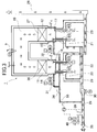
- a heat storage type exhaust gas purifying apparatus 1 includes a combustion chamber 10 and a pair of heat storages in which one end (upper end) of the combustion chamber 10 is coupled and communicated. Chambers 11 and 12 (first heat storage chamber 11 and second heat storage chamber 12) are provided.
- the combustion chamber 10 is provided with a temperature detector 8 and a burner 9.
- the heat storage type exhaust gas purification apparatus 1 is provided at the other end (lower end) of each of the pair of heat storage chambers 11 and 12, has supply opening / closing valves 14 and 15, and supply ports 20 and 21 for supplying a gas to be processed. (First supply port 20, second supply port 21). Also, provided at the other end (lower end) of each of the pair of heat storage chambers 11, 12 are provided with discharge opening / closing valves 16, 17 and discharge ports 22, 23 (first discharge port 22, first discharge port) for discharging processed gas. 2 outlets 23).
- the heat storage type exhaust gas purifying apparatus 1 includes heat storage bodies 26 and 27 (first heat storage body 26 and second heat storage body) provided between the one end (upper end) and the other end (lower end) of the plurality of heat storage chambers 11 and 12, respectively.
- the heat storage bodies 26 and 27 have a structure in which ceramic members having a plurality of through holes are arranged adjacent to each other.
- the heat storage type exhaust gas purification apparatus 1 includes an exhaust duct 28 connected to the discharge ports 22 and 23.
- the exhaust duct 28 is a passage for discharging the treated gas from the regenerative exhaust gas purification apparatus 1 and leading it to a predetermined place.
- the heat storage type exhaust gas purification apparatus 1 includes a supply duct 29 connected to the supply ports 20 and 21.
- the supply duct 29 is a passage for supplying the gas to be treated into the regenerative exhaust gas purification device 1.
- the supply duct 29 is provided with a blower 30.
- the blower 30 guides the gas to be processed to the supply ports 20 and 21 and guides the heat storage chambers 11 and 12 and the combustion chamber 10. At the same time, the blower 30 guides the processed gas to the predetermined discharge location via the discharge ports 22 and 23 and the exhaust duct 28.
- the heat storage-type exhaust gas purification apparatus 1 connects the other end side of the heat storage chambers 11 and 12 and the supply duct 29 to merge the gas on the other end side of the heat storage chambers 11 and 12 with the gas before flowing into the blower 30.
- a circulation pipe 33 is provided.
- the circulation pipe 33 is connected to the supply duct 29 at a position on the upstream side of the blower 30. Therefore, the circulation pipe 33 temporarily passes the gas flowing into the other end side of the heat storage chambers 11 and 12 to the upstream side of the blower 30. Functions as return piping.
- the circulation pipe 33 is provided with a first on-off valve 31 for circulation pipe, a second on-off valve 32 for circulation pipe, and an adjustment valve 34 for circulation pipe.
- the first on-off valve 31 for circulation piping opens and closes the flow from the other end side of the one heat storage chamber 11 to the supply duct 29.
- the second on-off valve 32 for circulation piping opens and closes the flow from the other end side of the other heat storage chamber 12 to the supply duct 29.
- the adjustment valve 34 for circulation piping is provided in the circulation piping 33 and adjusts the flow rate of the gas joined to the supply duct 29 from the other end side of one and the other heat storage chambers 11 and 12.
- the circulation pipe 33 includes a first return pipe section 33a and a second return pipe section 33b connected from the lower portions 11a and 12a of the heat storage chambers 11 and 12, respectively, and the first and second return pipe sections 33a, And a joining pipe part 33d formed via a joining part 33c where 33b joins (the joining part 33c is formed of a branch pipe).
- This merging pipe portion 33 d is connected to the supply duct 29.
- the first open / close valve 31 for circulation piping is provided in the first return piping section 33a.
- the second on-off valve 32 for circulation piping is provided in the second return piping section 33b.
- the circulation piping adjustment valve 34 is provided in the merging piping section 33d.
- the heat storage type exhaust gas purification apparatus 1 includes a first temperature detector 35 that detects the temperature of the other end side portion (lower portion 11a) of the heat storage chamber 11, and the temperature of the other end side portion (lower portion 12a) of the heat storage chamber 12. And a second temperature detector 36 for detection. Further, the heat storage type exhaust gas purification apparatus 1 includes a control unit 37 for executing “exhaust gas purification mode for purifying gas to be treated” and “adherent matter removal mode for removing substances adhering to the heat storage body”, which will be described later in detail. .
- the supply duct 29 includes a supply opening / closing valve 38 between the supply source of the gas to be processed (exhaust gas discharge facility). Further, the supply duct 29 is connected to this duct, and is air at normal temperature (outside air) that is a gas for removing deposits on the gas to be treated before flowing into the blower 30 and before joining the circulation pipe 33. Are joined together.
- the junction 39 is provided with a junction on-off valve 40, and by opening the junction on-off valve 40, normal temperature air (outside air), which is a deposit removal gas, flows into the supply duct 29. It has become.
- the merging on-off valve 40 can maintain an open state or a closed state and can also adjust the opening degree, and can adjust the flow rate of the fluid to be merged from the merging portion 39. ing.
- a merge on-off valve 45 as shown in FIG. 6C may be used.
- the control unit 37 closes the supply on / off valve 38 and opens the merging on / off valves 40 and 45.
- the on-off valves 14 and 15 of the supply ports 20 and 21 and the on-off valves 16 and 17 of the discharge ports 22 and 23 are so-called poppet dampers (poppet valves), and are used for switching the gas flow direction.
- the on-off valves 14 to 17 have valve bodies 14a, 15a, 16a, and 17a and cylinders 14b, 15b, 16b, and 17b, respectively.
- the valve bodies 14a to 17a are movable in the vertical direction. That is, the valve bodies 14a to 17a are attached to the tips of the rods 14c, 15c, 16c and 17c of the cylinders 14b to 17b, and are moved according to the expansion and contraction of the rods 14c to 17c.
- the supply side (side to which the gas to be processed is supplied) and the exhaust side (side from which the processed gas is discharged) of the heat storage chambers 11 and 12 ) Is switched and operation is performed.
- the switching timing of the on-off valve may be based on the inlet / outlet temperature (the temperature of the supplied and exhausted gas measured by the temperature detector).
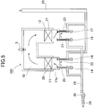
- FIGS. 2 and 3 show the flow of the gas to be processed and the treated gas that has been purified through the supply on / off valve 38 that has been opened.
- FIG. 2 it is assumed that the heat storage chamber 11 is on the supply side and the heat storage chamber 12 is on the discharge side.
- the exhaust gas to be processed reaches the heat storage chamber 11 through the supply port 20.
- the exhaust gas is heated by exchanging heat with the heat storage body 26 when passing through the heat storage body 26 on the heat storage chamber 11 side.
- the heat storage body 26 is radiated and cooled.
- the exhaust gas heated by the heat accumulator 26 and reaching the combustion chamber 10 undergoes combustion decomposition of components contained in the combustion chamber 10.
- the treated gas after combustion passes through the heat storage body 27 of the heat storage chamber 12. At this time, the treated gas is cooled by exchanging heat with the heat storage body 27. On the other hand, the heat storage body 27 is stored. The cooled treated gas passes through the discharge port 23 and reaches the exhaust duct 28.
- the heat storage body 26 of one heat storage chamber 11 is radiated and cooled, and the heat storage body 27 of the other heat storage chamber 12 is stored and heated.
- the on-off valve 14 of the supply port 20 of the heat storage chamber 11 is closed and the on-off valve 16 of the discharge port 22 is opened.
- the opening / closing valve 15 of the supply port 21 of the heat storage chamber 12 is opened, and the opening / closing valve 17 of the discharge port 23 is closed.
- the exhaust gas to be processed next can be heated by heat exchange with the heat storage body 27 that has sufficiently stored heat.
- the heated exhaust gas is processed in the combustion chamber 10 and is cooled and exhausted by heat exchange with the heat storage body 26.
- the on-off valve 14 of the supply port 20 of the heat storage chamber 11 is opened, and the on-off valve 16 of the discharge port 22 is closed.
- the opening / closing valve 15 of the supply port 21 of the heat storage chamber 12 is closed, and the opening / closing valve 17 of the discharge port 23 is opened.
- the controller 37 executes the deposit removal mode based on, for example, a preset time or the detection results of the first and second temperature detectors 35 and 36. First, the case where the high boiling-point filth adhering to the 2nd heat storage body 27 is removed in the deposit removal mode is demonstrated.
- the controller 37 closes the supply opening / closing valve 38 and opens the merging opening / closing valve 40. Further, as shown in FIG. 1, the control unit 37 opens the on-off valves 14 and 16 on the heat storage chamber 11 side and closes the on-off valves 15 and 17 on the heat storage chamber 12 side. The control unit 37 opens the second open / close valve 32 for the circulation pipe and closes (leaves closed) the first open / close valve 31 for the circulation pipe.
- control unit 37 sets the opening degree of the merging on-off valve 40 based on the detection output of the pressure detector 51 that detects the static pressure of the supply duct 29 after merging from the merging unit 39 (static pressure at the outside air intake portion). adjust. For example, it is desirable that the static pressure (static pressure at the outside air intake portion) is in the range of ⁇ 1.5 to 0 kPa.
- control unit 37 sets the air volume of the blower 30 to be constant (20 to 100% of the rated air volume). A certain amount of dilution is necessary from the viewpoint of temperature and the like, and it is 20% or more.
- the air is blown by the blower 30 and the outside air is introduced through the merging on-off valve 40.
- the gas (outside air) blown by the blower 30 flows into the lower portion 11 a of the heat storage chamber 11 through the supply port 20.
- the on-off valve 16 of the discharge port 22 is also opened, most of the outside air that has flowed in is discharged outside the apparatus through the discharge port 22 and the discharge duct 28 without passing through the heat storage body 26. Is done.
- the open / close valves 15 and 17 on the heat storage chamber 12 side are closed, the second open / close valve 32 for circulation piping on the heat storage chamber 12 side is opened, and the first open / close valve 31 for circulation piping on the heat storage chamber 11 side is closed. Therefore, a negative static pressure is applied to the lower portion 12a of the heat storage chamber 12. This is because the lower portion 12 a is connected to the suction side (upstream side) of the blower 30 by the circulation pipe 33. A part of the outside air (air) flowing into the lower portion 11 a of the heat storage chamber 11 from the supply port 20 due to the negative static pressure of the lower portion 12 a is stored as heat through the heat storage body 26, the combustion chamber 10, and the heat storage body 27. It flows to the lower part 12 a of the chamber 12. At this time, the air volume returned from the lower portion 12a to the supply pipe 29 via the circulation pipe 33 as the return pipe is adjusted by the circulation pipe adjustment valve 34.
- the control unit 37 controls the adjustment valve 34 for circulation piping so that the amount of air flowing through the circulation piping 33 falls within the range of 1 to 20% of the rated air volume of the blower 30.
- Material removal is possible. If it is less than 1%, sufficient hot air cannot be supplied to the heat accumulator, and therefore high boiling point substances cannot be removed. If it exceeds 20%, the heat storage body is heated suddenly, so that the heat storage body may be damaged by thermal shock.
- the rated air volume (rated gas volume) is the standard performance of the blower, which is the same as the maximum processing air volume in this heat storage type exhaust gas purification device.
- the outside air that has flowed to the heat storage body 26 of the heat storage chamber 11 is heated by the heat storage body 26 and further heated in the combustion chamber 10.
- the combustion chamber 10 is adjusted so that the output of the burner 9 is controlled by the control unit 37 based on the detection result of the temperature detector 8 and the inside of the combustion chamber 10 becomes about 500 to 1000 ° C.
- the outside air heated in the combustion chamber 10 passes through the heat storage body 27 of the heat storage chamber 12, heat exchange is performed with the heat storage body 27, so that the temperature of the heat storage body 27 rises. Thereby, the high boiling point substance adhering to the second heat storage body 27 is removed.
- the control unit 37 closes the on-off valves 14 and 16 on the heat storage chamber 11 side and opens the on-off valves 15 and 17 on the heat storage chamber 12 side.
- the control unit 37 closes the second on-off valve 32 for circulation piping and opens the first on-off valve 31 for circulation piping.
- a part of the outside air (air) flowing into the lower part 12 a flows to the lower part 11 a of the heat storage chamber 11 via the heat storage body 27, the combustion chamber 10, and the heat storage body 26, and supplies the supply duct 29 via the circulation pipe 33. Returned to Similarly to the case of the second heat storage body 27, the high boiling point substance of the first heat storage body 26 can also be removed.
- the temperature of the second heat storage body 27 is managed based on the detection result of the second temperature detector 36.
- the temperature is managed based on the detection result of the first temperature detector 35.
- the detection results by the first and second temperature detectors 35 and 36 are preferably about 100 to 500 ° C., respectively.
- the time required to remove the high-boiling substances adhering to the heat accumulator 27 and reach the so-called bakeout temperature is preferably about 1 to 5 hours.
- the holding time of the bakeout temperature is preferably 0 to 5 hours (may not be held).
- the bakeout temperature is about 100 to 500 ° C.
- the air passing through the circulation pipe 33 from the lower part 12 a of the heat storage chamber 12 is cooled by passing through the blower 30 by being mixed with the outside air taken in from the merging on-off valve 40. Thereby, it becomes unnecessary for the air blower 30 and the equipment which passes after that to have heat resistance. After completion of the heating and holding, cooling is performed slowly with a cooling time of 2 hours or more in order to prevent damage to the heat storage body.
- the heat storage combustion type exhaust gas purification apparatus 1 As described above, according to the heat storage combustion type exhaust gas purification apparatus 1 according to the present embodiment, it is possible to remove high-boiling substances attached to the heat storage body with a simple structure. Furthermore, it is not necessary for the blower 30 to be heat resistant. High boiling point substances can be removed while preventing damage to the heat accumulator, extending the service life of the heat accumulator.
- the control unit 37 of the heat storage combustion exhaust gas purification device 1 is provided with an on-off valve provided at the supply port of one heat storage chamber (for example, supply of the heat storage chamber 11 in the case of FIG. 2).
- the on-off valve 14 provided at the port 20 is open, the on-off valve provided at the discharge port (in the case of FIG. 2, the on-off valve 16 provided at the discharge port 22) is closed and the other heat storage An on-off valve provided at the discharge port (in the case of FIG. 2, the on-off valve 15 provided on the supply port 21 of the heat storage chamber 12 in the case of FIG. 2) is closed.
- the on-off valve is controlled so that the on-off valve 17) provided at 23 is opened.
- the control unit 37 switches the open / close valve 14 provided at the supply port of one heat storage chamber from open to closed (when switching so as to be in the state shown in FIG. 3).
- the on-off valve 16 provided at the discharge port of one heat storage chamber is switched from closed to open, the on-off valve 15 provided at the supply port of the other heat storage chamber is switched from closed to open, and the discharge of the other heat storage chamber is switched off.
- Each on-off valve is controlled so that the on-off valve 17 provided at the outlet is switched from open to closed.
- the control unit 37 opens the circulation piping on-off valves 31 and 32 provided in the one and other heat storage chambers 11 and 12 during the on-off switching operation of these on-off valves.
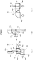
- the on-off valves 14 to 17 shown in FIG. 4 show a state in which the state of FIG. 2 is being transferred to the state of FIG. That is, during the switching operation of the poppet type open / close valves 14 to 17, both the discharge ports and the supply ports may be open.
- the control unit 37 switches the open / close valve 14 provided in the supply port of one of the heat storage chambers from closed to open (when switching to the state shown in FIG. 2).
- the on-off valve 16 provided at the discharge port of one heat storage chamber is switched from open to closed, and the on-off valve 15 provided at the supply port of the other heat storage chamber is switched from open to closed, and the other heat storage chamber
- the on-off valve is controlled so that the on-off valve 17 provided at the discharge port is switched from closed to open.
- the control unit 37 opens the circulation piping on-off valves 31 and 32 provided in the one and other heat storage chambers 11 and 12 during the on-off switching operation of these on-off valves. To control.
- the on-off valves 14 to 17 shown in FIG. 4 indicate a state in which the state is shifted from the state of FIG. 3 to the state of FIG. That is, during the switching operation of the poppet type open / close valves 14 to 17, both the discharge ports and the supply ports may be open.
- the control unit 37 closes the open / close valves 31 and 32 for the circulation pipe that have been opened after the open / close switching operation of the open / close valve is completed. That is, in the operation mode (exhaust gas purification mode) other than the switching operation of the on-off valve, basically, the on-off valves 31 and 32 for the circulation pipes provided in the one and other heat storage chambers 11 and 12 are closed. It is said that. In addition, between the start of the opening / closing switching operation of these on-off valves and the completion of the operation, the circulation piping on-off valves 31 and 32 are opened.
- the heat storage type exhaust gas purification apparatus 101 of the comparative example shown in FIG. 5 does not include the circulation pipe 33 and the circulation pipe on-off valves 31 and 32, and the other configurations are the same as those of the heat storage type exhaust gas purification apparatus 1 shown in FIGS. is there. That is, the heat storage type exhaust gas purification apparatus 101 includes a combustion chamber 10, heat storage chambers 11 and 12, on-off valves 14 to 17, and the like.
- FIG. 5 also shows the state during the switching operation of the on-off valves 14 to 17, as in FIG. In the state of FIG.
- the gas to be treated that has flowed into the lower portion 11 a of the heat storage chamber 11 from the supply port 20 does not flow into the combustion chamber 10 through the heat storage body 26, but enters the exhaust duct 28 through the discharge port 22.
- the direct inflow from the supply port 20 to the discharge port 22 may cause a slight leakage of the gas to be processed to the exhaust duct 28.
- the lower portions 11a and 12a of the heat storage chambers 11 and 12 are connected to the suction side of the blower 30 via the circulation pipe 33, and minus The gas to be processed is guided from the lower portions 11 a and 12 a to the supply duct 29 through the circulation pipe 33. Thereby, the outflow of the gas to be processed from the discharge ports 22 and 23 to the exhaust duct 28 can be prevented.
- the gas to be treated is prevented from being leaked to the exhaust duct 28 when the on-off valves 14 to 17 are switched, and the treatment of the gas to be treated is realized. To do. That is, the apparatus 1 can execute reliable exhaust gas treatment with a simple configuration.
- the junction open / close valve 40 includes a flow port forming member 41 provided with a flow port 41a, a valve body 42, an actuator 43 that drives the valve body 42 in the vertical direction, and an opening degree detection unit 44. Further, the main body 40a of the merging on-off valve 40 is provided with a fluid inlet 40b and a fluid outlet 40c.
- the valve body 42 includes a contact portion 42a that is movable in a direction toward and away from the flow port forming member 41, and a flow rate adjustment portion 42b that is integrally formed with the contact portion 42a. .
- the contact portion 42 a has a sealing surface, and is supplied from the flow port 41 a of the flow port forming member 41 when moved in a direction close to the flow port forming member 41 and brought into contact with the flow port forming member 41. The fluid is prevented from flowing into the duct 29.
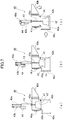
- FIG. 7A shows this fully closed state.
- the flow rate adjusting part 42b is inserted into the flow port 41a in a state where the contact part 42a is in contact with the flow port forming member 41.
- the flow rate adjusting part 42b is formed so that the gap through which the fluid flows between the flow port 41a gradually increases when the flow rate adjusting part 42b is moved away from the contacted part 42a.
- the flow rate adjusting unit 42b has a truncated cone shape (cone).
- FIG. 7B shows a state in which the gap (opening) is adjusted between the fully closed and fully opened flow rates.
- FIG. 7C shows a fully opened state.
- the actuator 43 is, for example, an air cylinder.
- the rod 43a of the actuator 43 is provided with a sliding member 43b having a sliding surface 43c. That is, the flow rate adjusting part 42b is provided at one end of the rod 43a, and the sliding member 43b is provided at the other end of the rod 43a.
- the opening degree detection unit 44 has an abutting member 44a that abuts against the sliding surface 43c.
- the contact member 44a is urged toward the sliding surface 43c by an urging member (not shown).
- the sliding surface 43c is inclined with respect to the vertical surface.
- the opening degree detection unit 44 detects the position of the rod 43a of the actuator 43, that is, the position of the flow rate adjustment unit 42b, based on the angle of the contact member 44a. Depending on the position of the flow rate adjusting part 42b, the gap through which the fluid flows changes, and the opening degree changes accordingly. In this manner, the opening degree detection unit 44 can detect the opening degree of the merging fluid on-off valve 40.
- the combined fluid on-off valve 40 has both a cutoff function and an adjustment function. That is, as shown in FIGS. 7A to 7C, the merging on-off valve 40 can maintain an open state or a closed state and can adjust an opening degree, and can be fluid that is merged from the merging portion 39 to the supply duct 29. The flow rate can be adjusted. Since the merge fluid on-off valve 40 has both a blocking function and an adjustment function, the installation space can be reduced as compared with the merge fluid on-off valve 45 shown in FIG. In addition, since both the shutoff and adjustment functions can be performed by driving one valve element 42, the control is simplified and the electrical wiring can be reduced.
- the merging on-off valve 40 is insufficient when the discharge amount of the gas to be processed, that is, the supply amount to the supply duct 29 decreases and becomes smaller than the minimum suction air amount (about 1/3 of the rated air amount) of the blower 30. Can be supplied.
- the merging on-off valve 40 supplies the outside air even when the concentration of the gas to be processed is high, thereby appropriately adjusting the concentration of the gas supplied from the supply duct 29 to the heat storage chambers 11, 12, etc. Realize proper operation.
- the merging on-off valve 40 can also adjust the flow rate of the inflowing air during the above-described deposit removal mode.
- the merging on-off valve of the heat storage type exhaust gas purification apparatus 1 is not limited to the merging on-off valve 40 shown in FIG.
- a merging on-off valve 45 shown in FIG. 6C includes a flow rate adjusting valve body 46 having a flow rate adjusting function, and an opening / closing valve body 47 having a function of holding a closed state (blocking) and an open state.
- the main body 45a of the merging on-off valve 45 is provided with a fluid inlet 45b and a fluid outlet 45c.
- the valve body 47 is a poppet damper (poppet valve) and is driven by an actuator 48 such as an air cylinder.
- the valve body 47 is fully closed by contacting the fluid outlet 45c, and is fully opened by being separated from the fluid outlet 45c.
- the valve body 46 is a butterfly damper (butterfly valve), and adjusts the flow rate by rotating.
- the merging on / off valve 45 also has a function of blocking and adjusting. That is, the merging on-off valve 45 can maintain the open state or the closed state, and the opening degree can be adjusted similarly to the merging on-off valve 40, and the flow rate of the fluid to be merged from the merging portion 39 to the supply duct 29 is adjusted it can.
- the on-off valves 14, 15, 16, and 17 provided at the supply port and the discharge port of the heat storage chambers 11 and 12 include a flow port forming member 61 having a flow port 61a and a valve. It has bodies 14a, 15a, 16a, 17a and cylinders 14b, 15b, 16b, 17b.
- the flow port forming member 61 also serves as the bottom of the heat storage chambers 11 and 12.
- a seal member 61 b is provided on the upper surface side of the circulation port forming member 61. As the seal member 61b, for example, non-asbestos packing may be used.
- the valve bodies 14a to 17a are in contact with the seal member 61b, thereby blocking the gas flow and maintaining the closed state.
- the on-off valve for the supply port and the discharge port of the heat storage type exhaust gas purification apparatus 1 is not limited to the on-off valve shown in FIG.
- the on-off valve 65 shown in FIG. 8B has a first member 66 provided with a gas flow port (hereinafter referred to as “flow port”) 66 a through which gas flows, and in a direction approaching and separating from the first member 66. It has the 2nd member 67 made movable, and the drive part 68b which drives the 2nd member 67 in the direction contact
- the second member 67 is in contact with the first member 66 to close the circulation port 66 a and is separated from the first member 66 to open the circulation port 66 a.
- the first member 66 is a circulation port forming member.
- the 2nd member 67 is a valve body, and is moved according to the expansion-contraction of the rod 68c of the drive part 68b.
- One of the first and second members 66 and 67 (the second member 67 in FIG. 8B) is integrally provided with an enclosing wall 69 formed so as to surround a portion outside the flow port 66a. Is done.
- the other of the first and second members 66 and 67 (the first member 66 in FIG. 8B) has a width wider than the thickness of the surrounding wall portion 69 and flows at a position corresponding to the surrounding wall portion 69.
- a seal member 64 is provided so as to surround the mouth 66a.
- the seal member 64 is attached to an attachment member 64 a provided on the first member 66.
- the seal member 64 is deformed when the first and second members 66 and 67 are close to each other and the surrounding wall portion 69 is brought into contact with the seal member 64 to prevent the gas from flowing out from the contact portion.
- a soft material is suitable for the seal member 64, and may be, for example, a binder, a silicon sponge, or a neoprene sponge.
- the thickness of the surrounding wall portion 69 is set to such a thickness that the seal member can be deformed by its edge when it comes into contact with the seal member 64, for example, about 10 mm to 50 mm.
- the above-described on-off valve 65 can increase the sealing pressure per unit area by reducing the contact area due to the surrounding wall portion 69 having an edge and the soft sealing member 64. Therefore, the on-off valve 65 can reduce fluid leakage.
- the heat storage type exhaust gas purification apparatus 1 may further include a first bypass duct 71 and a second bypass duct 72 connected to the combustion chamber 10.
- a heat storage type exhaust gas purifying apparatus 70 to which such first and second bypass ducts 71 and 72 and the like are added is shown in FIGS.
- casing of the combustion chamber 10 and the thermal storage chambers 11 and 12 is comprised integrally.
- the first bypass duct 71 communicates the combustion chamber 10 and the exhaust duct 28, that is, a bypass passage communicating the combustion chamber 10 and the discharge sides of the discharge ports 22 and 23.
- the first bypass duct 71 functions as a heat exhaust damper.
- the first bypass duct 71 has an adjustment valve 73.
- the adjustment valve 73 is a butterfly valve, and can adjust the flow rate of the flowing gas by the rotational force of the valve body.
- the first bypass duct 71 can discharge combustion gas for equipment protection when surplus heat is generated.
- the second bypass duct 72 is a heat recovery duct for using heat generated in the combustion chamber 10 in a heat recovery system 74 provided outside.
- the second bypass duct 72 has an adjustment valve 75 similar to the adjustment valve 73.
- the second bypass duct 72 communicates the combustion chamber 10 with the heat recovery system 74 and guides the treated gas after combustion in the combustion chamber 10 to the heat recovery system 74.
- the heat recovery system 74 is a waste heat boiler such as a furnace tube type.
- the heat recovery system 74 includes a water supply unit 74a that supplies water (soft water or the like) that exchanges heat with the exhaust gas from the combustion chamber 10, and a steam recovery unit that recovers steam generated when heat is applied to the water. 74b. Further, the heat recovery system 74 has an exhaust gas discharge part 74c for discharging the processed gas after heat exchange.
- the heat storage type exhaust gas purification device 70 includes a regulating valve 76 provided in the exhaust duct 28 and a pressure detector 77 for detecting the pressure in the combustion chamber 10.
- the control unit 37 can control the adjustment valve 76 based on the detection result of the pressure detector 77 to perform heat recovery and heat discharge, thereby realizing effective use of surplus heat.
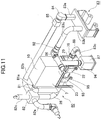
- both the first and second bypass ducts 71 and 72 are provided as the surplus heat discharge ducts. Is not limited to this. That is, also in the heat storage type exhaust gas purification device 80 having only the bypass duct 81 shown in FIGS. 9B and 11, the same effect as that of the above-described heat storage type exhaust gas purification device 70 can be obtained. That is, the heat storage type exhaust gas purification device 80 is obtained by adding a bypass duct 81, a heat exchanger 82, and the like to the heat storage type exhaust gas purification device 1.
- the bypass duct 81 communicates the combustion chamber 10 and the exhaust duct 28, that is, communicates the combustion chamber 10 with the discharge sides of the discharge ports 22 and 23. To do.
- the bypass duct 81 functions as a heat exhaust damper.
- the bypass duct 81 has an adjustment valve 81 a similar to the adjustment valve 73.
- the bypass duct 81 can discharge combustion gas for equipment protection when surplus heat is generated.
- the heat exchanger 82 is provided for heat recovery and is disposed in the exhaust duct 28.
- the heat exchanger 82 is, for example, a plate heat exchanger that performs heat exchange between gas and gas.
- the heat exchanger 82 includes an air supply unit 82a that supplies an atmosphere for heat exchange with the processed gas from the combustion chamber 10 and the like, and a hot air conduction unit 82b that guides hot air generated by the heat applied to the air. .
- the heat exchanger 82 has a gas discharge part 82c for discharging the processed gas after heat exchange.
- FIG. 11 shows an example in which the recovered heat is guided to a coater (coating) & drying line 83 and used. That is, the heat storage type exhaust gas purification device 80 shown in FIG. 11 is used to purify the exhaust gas from the coater & drying line 83, collect the heat generated by the device 80, and reuse it in the coater & drying line 83. An example was shown.
- the coater & drying line 83 has a supply unit 83a for supplying hot air for drying and a discharge unit 83b for discharging exhaust gas after being used for drying.
- the supply unit 83 a is connected to the hot air conduction unit 82 b via the fan 84 and the temperature regulator 85.
- the discharge part 83 b is connected to a conduction duct 83 c that leads to the supply duct 29.
- the conduction duct 83 c is provided with a fan 86, a filter box 87, and a fan 88, and guides exhaust gas from the discharge portion 83 b to the supply duct 29.
- the heat storage type exhaust gas purification device 80 includes a regulating valve 76 and a pressure detector 77, similarly to the device 70.
- the heat storage type exhaust gas purification device 80 as described above realizes effective use of surplus heat.
- the regenerative exhaust gas purification devices 70 and 80 also have the same configuration as the device 1 described above, that is, although not shown in FIGS. 9 to 11, the circulation pipe 33, the first and second on-off valves 31 for the circulation pipe. 32, a regulating valve 34 for circulation piping, first and second temperature detectors 35, 36, a control unit 37, and the like. Therefore, similarly to the device 1, the devices 70 and 80 can remove the high-boiling substances attached to the heat storage body with a simple structure, and can also exhibit the other functions and effects described above.
- Thermal storage exhaust gas purification device 9 Burner 10 Combustion chamber 11, 12 A pair of thermal storage chambers (first thermal storage chamber, second thermal storage chamber) 14, 15 Supply open / close valve 16, 17 Discharge open / close valve 20, 21 Supply port 22, 23 Discharge port 28 Exhaust duct 29 Supply duct 30 Blower 31 First open / close valve for circulation pipe 32 Second open / close valve for circulation pipe 34 Circulation Piping adjustment valve 35 First temperature detector 36 Second temperature detector 37 Control unit 38 Supply on / off valve 40, 45 Merge on / off valve
Landscapes
- Engineering & Computer Science (AREA)
- Environmental & Geological Engineering (AREA)
- Mechanical Engineering (AREA)
- General Engineering & Computer Science (AREA)
- Physics & Mathematics (AREA)
- Thermal Sciences (AREA)
- Incineration Of Waste (AREA)
Abstract
Description
このように構成された本発明においては、従来の蓄熱式排ガス処理装置に対して、第1蓄熱室及び第2蓄熱室のそれぞれの他端側と供給通路を接続する循環通路と、循環通路に設けられた循環通路用第1開閉弁及び循環通路用第2開閉弁とを設けるという簡易な構造により、「排ガス浄化モード」に加えて、「付着物除去モード」を実行することができ、この「付着物除去モード」により、第1蓄熱体及び第2蓄熱体に付着した高沸点物質を除去することができる。
このように構成された本発明においては、循環通路が供給通路の送風機の上流側の位置に接続されているので、送風機の上流側の位置で、循環通路により供給通路に戻される付着物除去用ガスが新たに供給通路の流入する付着物除去用ガスと混合されることで冷却され、これにより、送風機及び送風機の下流側の設備が耐熱性を有する必要がなくなる。
このように構成された本発明においては、第1温度検出器及び第2温度検出器により検出された温度が所定範囲内のときに、付着物除去モードが実行されるので、第1蓄熱体及び第2蓄熱体に付着した高沸点物質を確実に除去することができる。
このように構成された本発明においては、循環通路用調整弁により供給通路へ戻される付着物除去用ガスの流量を調整するので、第1蓄熱体及び第2蓄熱体に供給される熱風の量を制御できるので、適切な高沸点物質の除去が可能となる。
このように構成された本発明によれば、循環通路を流れる風量が送風機の定格風量の1~20%の範囲内であるので、高沸点物質の除去に必要な熱風を第1蓄熱体及び第2蓄熱体に供給することができ且つ急激に加熱することによる第1蓄熱体及び第2蓄熱体の損傷を防止できる。
このように構成された本発明においては、排ガス浄化モードにおいて、供給用開閉弁及び排出用供給弁の全てが開状態のとき、循環通路用第1開閉弁及び循環通路用第2開閉弁の両方が開となるように制御するので、供給用開閉弁及び排出用供給弁の全てが開状態のときに被処理ガスが漏洩することを防止できる。
このように構成された本発明においては、合流用開閉弁が開状態又は閉状態を保持でき且つ開度を調整できるので、設置スペースを小さくでき、制御が簡単となる。さらに、合流開閉弁の開度を調整して、被処理ガスの付着物除去用ガスの混合割合を最適に制御することができる。
さらに、蓄熱式排ガス浄化装置1は、詳細は後述する「被処理ガスを浄化する排ガス浄化モード」と「蓄熱体に付着した物質を除去する付着物除去モード」を実行するための制御部37と、を備える。
先ず、図2に示すように、蓄熱室11が供給側で、蓄熱室12が排出側であるとする。処理される排気ガスは、供給口20を通って蓄熱室11に到達する。
制御部37は、例えば、予め設定した時間や、第1及び第2温度検出器35,36の検出結果に基づいて、付着物除去モードを実行する。
まず、付着物除去モードにおいて、第2蓄熱体27に付着した高沸点汚物を除去する場合を説明する。制御部37は、供給用開閉弁38を閉とし、合流用開閉弁40を開とする。また、制御部37は、図1に示すように、蓄熱室11側の開閉弁14,16を開とし、蓄熱室12側の開閉弁15,17を閉とする。制御部37は、循環配管用第2開閉弁32を開とし、循環配管用第1開閉弁31を閉(閉のまま)とする。
9 バーナ
10 燃焼室
11,12 一対の蓄熱室(第1蓄熱室、第2蓄熱室)
14,15 供給用開閉弁
16,17 排出用開閉弁
20,21 供給口
22,23 排出口
28 排気ダクト
29 供給ダクト
30 送風機
31 循環配管用第1開閉弁
32 循環配管用第2開閉弁
34 循環配管用調整弁
35 第1温度検出器
36 第2温度検出器
37 制御部
38 供給用開閉弁
40,45 合流用開閉弁
Claims (10)
- 蓄熱体を用いて被処理ガスを浄化する蓄熱式排ガス浄化装置であって、
第1蓄熱体及び第2蓄熱体をそれぞれ収容する第1蓄熱室及び第2蓄熱室と、
これらの第1蓄熱室及び第2蓄熱室のそれぞれの一端に連通するように設けられた、加熱手段を備えた燃焼室と、
上記第1蓄熱室及び第2蓄熱室のそれぞれの他端に設けられ、供給用開閉弁を備えるとともに被処理ガスを供給するための第1供給部及び第2供給部と、
上記第1蓄熱室及び第2蓄熱室のそれぞれの他端に設けられ、排出用開閉弁を備えるとともに処理済ガスを排出するための第1排出部及び第2排出部と、
上記第1供給部及び第2供給部に接続され、被処理ガスを供給するための供給通路と、
この供給通路に設けられ、被処理ガスを上記第1供給部及び第2供給部に導く送風機と、
上記第1蓄熱室及び第2蓄熱室のそれぞれの他端側と上記供給通路を接続する循環通路と、
上記循環通路に設けられ、上記第1蓄熱室の他端側から上記供給通路への流れの開閉を行う循環通路用第1開閉弁と、
上記循環通路に設けられ、上記第2蓄熱室の他端側から上記供給通路への流れの開閉を行う循環通路用第2開閉弁と、
被処理ガスを浄化する排ガス浄化モードと、付着物除去用ガスを用いて上記第1蓄熱体及び第2蓄熱体に付着した物質を除去する付着物除去モードと、を実行する制御部と、を有し、
上記制御部は、上記付着物除去モードにおいて、上記送風機を作動させて付着物除去用ガスを供給通路に流入させ、この付着物除去用ガスが、第2蓄熱体を通過して加熱され、燃料室で加熱され、第1蓄熱体を通過することにより、第1蓄熱体の温度を上昇させて、第1蓄熱体に付着した物質を除去し、その後、付着物除去用ガスを循環通路を経て供給通路に戻し、且つ、上記送風機を作動させて付着物除去用ガスを供給通路に流入させ、この付着物除去用ガスが、第1蓄熱体を通過して加熱され、燃料室で加熱され、第2蓄熱体を通過することにより、第2蓄熱体の温度を上昇させて、第2蓄熱体に付着した物質を除去し、その後、付着物除去用ガスを循環通路を経て供給通路に戻すように、上記供給用開閉弁、排出用開閉弁、循環通路用第1開閉弁、循環通路用第2開閉弁を制御することを特徴とする蓄熱式排ガス浄化装置。 - 上記循環通路は、第1蓄熱室及び第2蓄熱室のそれぞれの他端側と上記供給通路の上記送風機の上流側の位置とを接続する請求項1に記載の蓄熱式排ガス処理装置。
- 更に、第1蓄熱室の他端側の温度を検出する第1温度検出器と、第2蓄熱室の他端側の温度を検出する第2温度検出器を有し、上記制御部は、上記第1温度検出器及び第2温度検出器により検出された温度が所定範囲内のときに、上記付着物除去モードを実行する請求項2に記載の蓄熱式排ガス浄化装置。
- 更に、上記循環通路に設けられ、付着物除去モードの実行時に、上記供給通路へ戻される付着物除去用ガスの流量を調整する循環通路用調整弁と、を有し、
上記制御部は、上記付着物除去モードにおいて、上記循環通路用調整弁の開度を制御する請求項3に記載の排ガス浄化装置。 - 上記制御部は、上記循環通路を流れる風量が上記送風機の定格風量の1~20%の範囲内となるように上記循環通路用調整弁の開度を制御する請求項4に記載の蓄熱式排ガス浄化装置。
- 上記制御部は、排ガス浄化モードにおいて、上記供給用開閉弁及び排出用供給弁の開閉切換動作中に、上記供給用開閉弁及び排出用供給弁の全てが開状態のとき、上記循環通路用第1開閉弁及び循環通路用第2開閉弁の両方が開となるように制御し、さらに、上記開閉切換動作完了時に、上記循環通路用第1開閉弁及び循環通路用第2開閉弁の両方が閉となるように制御する請求項5に記載の蓄熱式排ガス浄化装置。
- 更に、上記供給通路に接続され、上記送風機に流入する前の被処理ガスに上記付着物除去用ガスを合流させる合流部に設けられる合流用開閉弁を有し、
この合流用開閉弁は、開状態又は閉状態を保持でき且つ開度を調整できる請求項6に記載の蓄熱式排ガス浄化装置。 - 上記合流用開閉弁は、流通口が設けられた流通口形成部材と、
この流通口形成部材に対して近接する方向及び離間する方向に移動可能である当接部と、この当接部に一体に形成される流量調整部とを備えた弁体と、を有し、
上記当接部は、流通口形成部材に近接する方向に移動して流通口形成部材に当接したときに、流通口形成部材の流通口から供給通路へ付着物除去用ガスが流入することを阻止し、
上記流量調整部は、当接部が流通口形成部材に当接した状態で流通口に挿入され、当接部が当接した状態から離間する方向に移動したときに、流通口との間の流体が流通する隙間が漸次大きくなるように形成されている請求項7に記載の蓄熱式排ガス浄化装置。 - 上記流量調整部は、円錐台形状部により形成されている請求項8に記載の蓄熱式排ガス浄化装置。
- 上記供給用開閉弁及び排出用開閉弁は、それぞれ、被処理ガス又は処理済ガスが流通するガス流通口が設けられた第1部材と、
上記第1部材に対して近接及び離間する方向に移動可能とされ、第1部材に当接してガス流通口を閉とするとともに、第1部材から離間してガス流通口を開とする第2部材と、
この第2部材を当接及び離間する方向に駆動する駆動部と、を有し、
これらの第1部材及び第2部材のいずれか一方には、ガス流通口より外側の部分を囲う包囲壁部が一体的に形成され、第1及び第2部材のいずれか他方には、包囲壁部に対応する位置に、包囲壁部の厚みより太い幅で且つガス流通口を囲うように形成され、第1及び第2部材が近接して包囲壁部が当接されたときに変形してこの当接部分からの被処理瓦斯の流出を防止するシール部材が設けられている請求項7記載の蓄熱式排ガス浄化装置。
Priority Applications (2)
| Application Number | Priority Date | Filing Date | Title |
|---|---|---|---|
| CN201380025604.5A CN104302977B (zh) | 2012-07-12 | 2013-02-18 | 蓄热式废气净化装置 |
| JP2014524660A JP6066460B2 (ja) | 2012-07-12 | 2013-02-18 | 蓄熱式排ガス浄化装置 |
Applications Claiming Priority (2)
| Application Number | Priority Date | Filing Date | Title |
|---|---|---|---|
| JP2012-156317 | 2012-07-12 | ||
| JP2012156317 | 2012-07-12 |
Publications (1)
| Publication Number | Publication Date |
|---|---|
| WO2014010262A1 true WO2014010262A1 (ja) | 2014-01-16 |
Family
ID=49915741
Family Applications (1)
| Application Number | Title | Priority Date | Filing Date |
|---|---|---|---|
| PCT/JP2013/053828 Ceased WO2014010262A1 (ja) | 2012-07-12 | 2013-02-18 | 蓄熱式排ガス浄化装置 |
Country Status (4)
| Country | Link |
|---|---|
| JP (1) | JP6066460B2 (ja) |
| CN (1) | CN104302977B (ja) |
| TW (1) | TWI553276B (ja) |
| WO (1) | WO2014010262A1 (ja) |
Cited By (2)
| Publication number | Priority date | Publication date | Assignee | Title |
|---|---|---|---|---|
| EP2878886A1 (de) * | 2013-11-27 | 2015-06-03 | Caverion Deutschland GmbH | Verfahren zum Betrieb einer Gasoxidationsanlage |
| CN110397944A (zh) * | 2019-07-29 | 2019-11-01 | 浙江天地环保科技有限公司 | 一种rto装置组合切换阀及运行方法 |
Families Citing this family (4)
| Publication number | Priority date | Publication date | Assignee | Title |
|---|---|---|---|---|
| KR101663599B1 (ko) * | 2015-05-28 | 2016-10-07 | 주식회사 디복스 | 축열식 산화장치의 베이크아웃 장치 및 방법 |
| DE102017101507B4 (de) * | 2017-01-26 | 2022-10-13 | Chemisch Thermische Prozesstechnik Gmbh | Verfahren und Vorrichtung zur Abgasreinigung |
| JP7484839B2 (ja) * | 2021-07-26 | 2024-05-16 | 株式会社村田製作所 | 加熱炉 |
| ES2993272T3 (en) * | 2022-02-25 | 2024-12-26 | Megtec Systems Ab | Regenerative thermal fluid purification device and method for operating a regenerative thermal fluid purification device |
Citations (3)
| Publication number | Priority date | Publication date | Assignee | Title |
|---|---|---|---|---|
| JPH09152120A (ja) * | 1995-11-30 | 1997-06-10 | Trinity Ind Corp | 蓄熱型脱臭処理装置 |
| JP2008045818A (ja) * | 2006-08-16 | 2008-02-28 | Kobelco Eco-Solutions Co Ltd | 蓄熱式燃焼脱臭装置 |
| JP2011133131A (ja) * | 2009-12-22 | 2011-07-07 | Taikisha Ltd | 蓄熱式ガス処理装置の清掃運転方法、及び、蓄熱式ガス処理装置 |
Family Cites Families (9)
| Publication number | Priority date | Publication date | Assignee | Title |
|---|---|---|---|---|
| US5240403A (en) * | 1992-09-01 | 1993-08-31 | Moco Thermal Industries, Inc. | Regenerative thermal oxidation apparatus and method |
| JP2003161424A (ja) * | 2001-11-20 | 2003-06-06 | Sintokogio Ltd | 蓄熱燃焼装置 |
| JP2006250384A (ja) * | 2005-03-09 | 2006-09-21 | Sintokogio Ltd | 蓄熱燃焼式排ガス浄化装置におけるハニカム状セラミックス製蓄熱体およびその製造方法 |
| TWI276756B (en) * | 2005-08-26 | 2007-03-21 | Superior Air Treat Technology | Regenerative thermal oxidizer |
| JP4341035B2 (ja) * | 2005-10-04 | 2009-10-07 | 新東工業株式会社 | ポペット式ダンパおよび該ポペット式ダンパを用いる排ガス処理装置 |
| CN101561145A (zh) * | 2008-04-16 | 2009-10-21 | 华懋科技股份有限公司 | 外气除净式蓄热焚化炉 |
| TW201038884A (en) * | 2009-04-17 | 2010-11-01 | Jg Environmental Tech Co Ltd | Wind speed variable heat storage incinerator and method for controlling the same |
| CN201706514U (zh) * | 2010-05-20 | 2011-01-12 | 江苏大信环境科技有限公司 | 蓄热式废气焚烧炉 |
| CN102782409B (zh) * | 2010-10-05 | 2015-07-29 | 新东工业株式会社 | 废气净化装置及其温度控制方法 |
-
2013
- 2013-02-18 CN CN201380025604.5A patent/CN104302977B/zh active Active
- 2013-02-18 JP JP2014524660A patent/JP6066460B2/ja active Active
- 2013-02-18 WO PCT/JP2013/053828 patent/WO2014010262A1/ja not_active Ceased
- 2013-03-06 TW TW102107784A patent/TWI553276B/zh active
Patent Citations (3)
| Publication number | Priority date | Publication date | Assignee | Title |
|---|---|---|---|---|
| JPH09152120A (ja) * | 1995-11-30 | 1997-06-10 | Trinity Ind Corp | 蓄熱型脱臭処理装置 |
| JP2008045818A (ja) * | 2006-08-16 | 2008-02-28 | Kobelco Eco-Solutions Co Ltd | 蓄熱式燃焼脱臭装置 |
| JP2011133131A (ja) * | 2009-12-22 | 2011-07-07 | Taikisha Ltd | 蓄熱式ガス処理装置の清掃運転方法、及び、蓄熱式ガス処理装置 |
Cited By (2)
| Publication number | Priority date | Publication date | Assignee | Title |
|---|---|---|---|---|
| EP2878886A1 (de) * | 2013-11-27 | 2015-06-03 | Caverion Deutschland GmbH | Verfahren zum Betrieb einer Gasoxidationsanlage |
| CN110397944A (zh) * | 2019-07-29 | 2019-11-01 | 浙江天地环保科技有限公司 | 一种rto装置组合切换阀及运行方法 |
Also Published As
| Publication number | Publication date |
|---|---|
| TW201403003A (zh) | 2014-01-16 |
| TWI553276B (zh) | 2016-10-11 |
| JP6066460B2 (ja) | 2017-01-25 |
| CN104302977B (zh) | 2016-08-31 |
| CN104302977A (zh) | 2015-01-21 |
| JPWO2014010262A1 (ja) | 2016-06-20 |
Similar Documents
| Publication | Publication Date | Title |
|---|---|---|
| JP6066460B2 (ja) | 蓄熱式排ガス浄化装置 | |
| TWI599747B (zh) | 蓄熱式排放氣體淨化裝置 | |
| CN102498345B (zh) | 蓄热燃烧式废气净化系统及其运转方法 | |
| TWI644726B (zh) | 熱再活化的吸附劑氣體分餾器及程序 | |
| JP6041105B2 (ja) | 蓄熱式排ガス浄化装置 | |
| JP2012526964A (ja) | 再生式の熱交換器およびそこにおけるガスの漏れを減らす方法 | |
| JPH0712477A (ja) | 蓄熱式熱交換器及びその作動方法 | |
| KR20180034338A (ko) | 배기 시스템 | |
| JP5937399B2 (ja) | 蓄熱式ガス処理装置の運転方法、及び、蓄熱式ガス処理装置 | |
| CN103398590B (zh) | 热回收装置 | |
| KR101057276B1 (ko) | 보일러 배기열 회수형 환기시스템 | |
| CN116398894A (zh) | 一种用于处理特殊废气的防腐蚀七室蓄热焚烧设备 | |
| JP3548833B2 (ja) | 排ガス処理システム及びその運転方法 | |
| JP2003074826A (ja) | 蓄熱燃焼装置 | |
| JP6157909B2 (ja) | 排熱回収ボイラおよびその制御方法 | |
| JP6634118B2 (ja) | 熱利用システム及び熱利用システムの運転方法 | |
| JP6076241B2 (ja) | ガス処理装置 | |
| WO2023043388A3 (en) | Waste thermal energy recovery device | |
| JP2009127934A (ja) | 蓄熱式燃焼装置 | |
| JP6593245B2 (ja) | 排ガス処理装置及び排ガス処理方法 | |
| JP3853559B2 (ja) | 排ガス処理装置の腐食防止方法 | |
| KR101796714B1 (ko) | 연기처리장치 | |
| KR19980038994U (ko) | 배열회수 시스템용 순환수 장치 | |
| JP5373719B2 (ja) | 廃棄物処理設備の運転方法、保温装置および廃棄物処理設備 | |
| JP5675508B2 (ja) | Voc除害装置 |
Legal Events
| Date | Code | Title | Description |
|---|---|---|---|
| 121 | Ep: the epo has been informed by wipo that ep was designated in this application |
Ref document number: 13816070 Country of ref document: EP Kind code of ref document: A1 |
|
| ENP | Entry into the national phase |
Ref document number: 2014524660 Country of ref document: JP Kind code of ref document: A |
|
| WWE | Wipo information: entry into national phase |
Ref document number: IDP00201407035 Country of ref document: ID |
|
| NENP | Non-entry into the national phase |
Ref country code: DE |
|
| 122 | Ep: pct application non-entry in european phase |
Ref document number: 13816070 Country of ref document: EP Kind code of ref document: A1 |