WO2014010030A1 - 電力系統制御システム及び電力系統制御方法 - Google Patents
電力系統制御システム及び電力系統制御方法 Download PDFInfo
- Publication number
- WO2014010030A1 WO2014010030A1 PCT/JP2012/067615 JP2012067615W WO2014010030A1 WO 2014010030 A1 WO2014010030 A1 WO 2014010030A1 JP 2012067615 W JP2012067615 W JP 2012067615W WO 2014010030 A1 WO2014010030 A1 WO 2014010030A1
- Authority
- WO
- WIPO (PCT)
- Prior art keywords
- control
- power
- power system
- power state
- control amount
- Prior art date
Links
- 238000000034 method Methods 0.000 title claims description 54
- 238000005259 measurement Methods 0.000 claims abstract description 122
- 238000004891 communication Methods 0.000 claims abstract description 110
- 238000004364 calculation method Methods 0.000 claims description 131
- 230000006870 function Effects 0.000 description 33
- 230000014509 gene expression Effects 0.000 description 25
- 238000013500 data storage Methods 0.000 description 23
- 238000007726 management method Methods 0.000 description 19
- 238000012544 monitoring process Methods 0.000 description 19
- 230000005540 biological transmission Effects 0.000 description 14
- 238000012545 processing Methods 0.000 description 14
- 230000008569 process Effects 0.000 description 13
- 238000003860 storage Methods 0.000 description 13
- 239000003990 capacitor Substances 0.000 description 9
- 238000010586 diagram Methods 0.000 description 8
- 230000007704 transition Effects 0.000 description 7
- 230000008859 change Effects 0.000 description 5
- 238000004590 computer program Methods 0.000 description 5
- 238000011156 evaluation Methods 0.000 description 5
- 230000005611 electricity Effects 0.000 description 4
- 238000009434 installation Methods 0.000 description 4
- 238000010248 power generation Methods 0.000 description 4
- 238000005516 engineering process Methods 0.000 description 3
- 230000009466 transformation Effects 0.000 description 3
- XLYOFNOQVPJJNP-UHFFFAOYSA-N water Substances O XLYOFNOQVPJJNP-UHFFFAOYSA-N 0.000 description 3
- 238000009826 distribution Methods 0.000 description 2
- 238000009472 formulation Methods 0.000 description 2
- 238000002347 injection Methods 0.000 description 2
- 239000007924 injection Substances 0.000 description 2
- 239000000203 mixture Substances 0.000 description 2
- 238000012986 modification Methods 0.000 description 2
- 230000004048 modification Effects 0.000 description 2
- 239000000243 solution Substances 0.000 description 2
- 230000009471 action Effects 0.000 description 1
- 238000007792 addition Methods 0.000 description 1
- 230000009194 climbing Effects 0.000 description 1
- 230000003750 conditioning effect Effects 0.000 description 1
- 238000010411 cooking Methods 0.000 description 1
- 230000003111 delayed effect Effects 0.000 description 1
- 230000006866 deterioration Effects 0.000 description 1
- 230000000694 effects Effects 0.000 description 1
- 239000000446 fuel Substances 0.000 description 1
- 230000006872 improvement Effects 0.000 description 1
- 238000012886 linear function Methods 0.000 description 1
- 238000012423 maintenance Methods 0.000 description 1
- 238000004519 manufacturing process Methods 0.000 description 1
- 235000012054 meals Nutrition 0.000 description 1
- 230000003287 optical effect Effects 0.000 description 1
- 238000002360 preparation method Methods 0.000 description 1
- 230000003068 static effect Effects 0.000 description 1
- 238000012546 transfer Methods 0.000 description 1
Images


Classifications
-
- G—PHYSICS
- G05—CONTROLLING; REGULATING
- G05F—SYSTEMS FOR REGULATING ELECTRIC OR MAGNETIC VARIABLES
- G05F1/00—Automatic systems in which deviations of an electric quantity from one or more predetermined values are detected at the output of the system and fed back to a device within the system to restore the detected quantity to its predetermined value or values, i.e. retroactive systems
- G05F1/66—Regulating electric power
-
- G—PHYSICS
- G05—CONTROLLING; REGULATING
- G05B—CONTROL OR REGULATING SYSTEMS IN GENERAL; FUNCTIONAL ELEMENTS OF SUCH SYSTEMS; MONITORING OR TESTING ARRANGEMENTS FOR SUCH SYSTEMS OR ELEMENTS
- G05B13/00—Adaptive control systems, i.e. systems automatically adjusting themselves to have a performance which is optimum according to some preassigned criterion
- G05B13/02—Adaptive control systems, i.e. systems automatically adjusting themselves to have a performance which is optimum according to some preassigned criterion electric
- G05B13/04—Adaptive control systems, i.e. systems automatically adjusting themselves to have a performance which is optimum according to some preassigned criterion electric involving the use of models or simulators
-
- G—PHYSICS
- G05—CONTROLLING; REGULATING
- G05B—CONTROL OR REGULATING SYSTEMS IN GENERAL; FUNCTIONAL ELEMENTS OF SUCH SYSTEMS; MONITORING OR TESTING ARRANGEMENTS FOR SUCH SYSTEMS OR ELEMENTS
- G05B15/00—Systems controlled by a computer
- G05B15/02—Systems controlled by a computer electric
-
- G—PHYSICS
- G06—COMPUTING; CALCULATING OR COUNTING
- G06Q—INFORMATION AND COMMUNICATION TECHNOLOGY [ICT] SPECIALLY ADAPTED FOR ADMINISTRATIVE, COMMERCIAL, FINANCIAL, MANAGERIAL OR SUPERVISORY PURPOSES; SYSTEMS OR METHODS SPECIALLY ADAPTED FOR ADMINISTRATIVE, COMMERCIAL, FINANCIAL, MANAGERIAL OR SUPERVISORY PURPOSES, NOT OTHERWISE PROVIDED FOR
- G06Q10/00—Administration; Management
- G06Q10/04—Forecasting or optimisation specially adapted for administrative or management purposes, e.g. linear programming or "cutting stock problem"
-
- G—PHYSICS
- G06—COMPUTING; CALCULATING OR COUNTING
- G06Q—INFORMATION AND COMMUNICATION TECHNOLOGY [ICT] SPECIALLY ADAPTED FOR ADMINISTRATIVE, COMMERCIAL, FINANCIAL, MANAGERIAL OR SUPERVISORY PURPOSES; SYSTEMS OR METHODS SPECIALLY ADAPTED FOR ADMINISTRATIVE, COMMERCIAL, FINANCIAL, MANAGERIAL OR SUPERVISORY PURPOSES, NOT OTHERWISE PROVIDED FOR
- G06Q50/00—Information and communication technology [ICT] specially adapted for implementation of business processes of specific business sectors, e.g. utilities or tourism
- G06Q50/06—Energy or water supply
-
- H—ELECTRICITY
- H02—GENERATION; CONVERSION OR DISTRIBUTION OF ELECTRIC POWER
- H02J—CIRCUIT ARRANGEMENTS OR SYSTEMS FOR SUPPLYING OR DISTRIBUTING ELECTRIC POWER; SYSTEMS FOR STORING ELECTRIC ENERGY
- H02J13/00—Circuit arrangements for providing remote indication of network conditions, e.g. an instantaneous record of the open or closed condition of each circuitbreaker in the network; Circuit arrangements for providing remote control of switching means in a power distribution network, e.g. switching in and out of current consumers by using a pulse code signal carried by the network
- H02J13/00006—Circuit arrangements for providing remote indication of network conditions, e.g. an instantaneous record of the open or closed condition of each circuitbreaker in the network; Circuit arrangements for providing remote control of switching means in a power distribution network, e.g. switching in and out of current consumers by using a pulse code signal carried by the network characterised by information or instructions transport means between the monitoring, controlling or managing units and monitored, controlled or operated power network element or electrical equipment
- H02J13/00007—Circuit arrangements for providing remote indication of network conditions, e.g. an instantaneous record of the open or closed condition of each circuitbreaker in the network; Circuit arrangements for providing remote control of switching means in a power distribution network, e.g. switching in and out of current consumers by using a pulse code signal carried by the network characterised by information or instructions transport means between the monitoring, controlling or managing units and monitored, controlled or operated power network element or electrical equipment using the power network as support for the transmission
-
- H—ELECTRICITY
- H02—GENERATION; CONVERSION OR DISTRIBUTION OF ELECTRIC POWER
- H02J—CIRCUIT ARRANGEMENTS OR SYSTEMS FOR SUPPLYING OR DISTRIBUTING ELECTRIC POWER; SYSTEMS FOR STORING ELECTRIC ENERGY
- H02J13/00—Circuit arrangements for providing remote indication of network conditions, e.g. an instantaneous record of the open or closed condition of each circuitbreaker in the network; Circuit arrangements for providing remote control of switching means in a power distribution network, e.g. switching in and out of current consumers by using a pulse code signal carried by the network
- H02J13/00032—Systems characterised by the controlled or operated power network elements or equipment, the power network elements or equipment not otherwise provided for
- H02J13/00034—Systems characterised by the controlled or operated power network elements or equipment, the power network elements or equipment not otherwise provided for the elements or equipment being or involving an electric power substation
-
- H—ELECTRICITY
- H02—GENERATION; CONVERSION OR DISTRIBUTION OF ELECTRIC POWER
- H02J—CIRCUIT ARRANGEMENTS OR SYSTEMS FOR SUPPLYING OR DISTRIBUTING ELECTRIC POWER; SYSTEMS FOR STORING ELECTRIC ENERGY
- H02J3/00—Circuit arrangements for ac mains or ac distribution networks
- H02J3/12—Circuit arrangements for ac mains or ac distribution networks for adjusting voltage in ac networks by changing a characteristic of the network load
-
- H—ELECTRICITY
- H02—GENERATION; CONVERSION OR DISTRIBUTION OF ELECTRIC POWER
- H02J—CIRCUIT ARRANGEMENTS OR SYSTEMS FOR SUPPLYING OR DISTRIBUTING ELECTRIC POWER; SYSTEMS FOR STORING ELECTRIC ENERGY
- H02J3/00—Circuit arrangements for ac mains or ac distribution networks
- H02J3/18—Arrangements for adjusting, eliminating or compensating reactive power in networks
-
- H—ELECTRICITY
- H02—GENERATION; CONVERSION OR DISTRIBUTION OF ELECTRIC POWER
- H02J—CIRCUIT ARRANGEMENTS OR SYSTEMS FOR SUPPLYING OR DISTRIBUTING ELECTRIC POWER; SYSTEMS FOR STORING ELECTRIC ENERGY
- H02J4/00—Circuit arrangements for mains or distribution networks not specified as ac or dc
-
- Y—GENERAL TAGGING OF NEW TECHNOLOGICAL DEVELOPMENTS; GENERAL TAGGING OF CROSS-SECTIONAL TECHNOLOGIES SPANNING OVER SEVERAL SECTIONS OF THE IPC; TECHNICAL SUBJECTS COVERED BY FORMER USPC CROSS-REFERENCE ART COLLECTIONS [XRACs] AND DIGESTS
- Y02—TECHNOLOGIES OR APPLICATIONS FOR MITIGATION OR ADAPTATION AGAINST CLIMATE CHANGE
- Y02E—REDUCTION OF GREENHOUSE GAS [GHG] EMISSIONS, RELATED TO ENERGY GENERATION, TRANSMISSION OR DISTRIBUTION
- Y02E40/00—Technologies for an efficient electrical power generation, transmission or distribution
- Y02E40/30—Reactive power compensation
-
- Y—GENERAL TAGGING OF NEW TECHNOLOGICAL DEVELOPMENTS; GENERAL TAGGING OF CROSS-SECTIONAL TECHNOLOGIES SPANNING OVER SEVERAL SECTIONS OF THE IPC; TECHNICAL SUBJECTS COVERED BY FORMER USPC CROSS-REFERENCE ART COLLECTIONS [XRACs] AND DIGESTS
- Y02—TECHNOLOGIES OR APPLICATIONS FOR MITIGATION OR ADAPTATION AGAINST CLIMATE CHANGE
- Y02E—REDUCTION OF GREENHOUSE GAS [GHG] EMISSIONS, RELATED TO ENERGY GENERATION, TRANSMISSION OR DISTRIBUTION
- Y02E40/00—Technologies for an efficient electrical power generation, transmission or distribution
- Y02E40/70—Smart grids as climate change mitigation technology in the energy generation sector
-
- Y—GENERAL TAGGING OF NEW TECHNOLOGICAL DEVELOPMENTS; GENERAL TAGGING OF CROSS-SECTIONAL TECHNOLOGIES SPANNING OVER SEVERAL SECTIONS OF THE IPC; TECHNICAL SUBJECTS COVERED BY FORMER USPC CROSS-REFERENCE ART COLLECTIONS [XRACs] AND DIGESTS
- Y02—TECHNOLOGIES OR APPLICATIONS FOR MITIGATION OR ADAPTATION AGAINST CLIMATE CHANGE
- Y02E—REDUCTION OF GREENHOUSE GAS [GHG] EMISSIONS, RELATED TO ENERGY GENERATION, TRANSMISSION OR DISTRIBUTION
- Y02E60/00—Enabling technologies; Technologies with a potential or indirect contribution to GHG emissions mitigation
-
- Y—GENERAL TAGGING OF NEW TECHNOLOGICAL DEVELOPMENTS; GENERAL TAGGING OF CROSS-SECTIONAL TECHNOLOGIES SPANNING OVER SEVERAL SECTIONS OF THE IPC; TECHNICAL SUBJECTS COVERED BY FORMER USPC CROSS-REFERENCE ART COLLECTIONS [XRACs] AND DIGESTS
- Y04—INFORMATION OR COMMUNICATION TECHNOLOGIES HAVING AN IMPACT ON OTHER TECHNOLOGY AREAS
- Y04S—SYSTEMS INTEGRATING TECHNOLOGIES RELATED TO POWER NETWORK OPERATION, COMMUNICATION OR INFORMATION TECHNOLOGIES FOR IMPROVING THE ELECTRICAL POWER GENERATION, TRANSMISSION, DISTRIBUTION, MANAGEMENT OR USAGE, i.e. SMART GRIDS
- Y04S10/00—Systems supporting electrical power generation, transmission or distribution
- Y04S10/22—Flexible AC transmission systems [FACTS] or power factor or reactive power compensating or correcting units
-
- Y—GENERAL TAGGING OF NEW TECHNOLOGICAL DEVELOPMENTS; GENERAL TAGGING OF CROSS-SECTIONAL TECHNOLOGIES SPANNING OVER SEVERAL SECTIONS OF THE IPC; TECHNICAL SUBJECTS COVERED BY FORMER USPC CROSS-REFERENCE ART COLLECTIONS [XRACs] AND DIGESTS
- Y04—INFORMATION OR COMMUNICATION TECHNOLOGIES HAVING AN IMPACT ON OTHER TECHNOLOGY AREAS
- Y04S—SYSTEMS INTEGRATING TECHNOLOGIES RELATED TO POWER NETWORK OPERATION, COMMUNICATION OR INFORMATION TECHNOLOGIES FOR IMPROVING THE ELECTRICAL POWER GENERATION, TRANSMISSION, DISTRIBUTION, MANAGEMENT OR USAGE, i.e. SMART GRIDS
- Y04S10/00—Systems supporting electrical power generation, transmission or distribution
- Y04S10/30—State monitoring, e.g. fault, temperature monitoring, insulator monitoring, corona discharge
-
- Y—GENERAL TAGGING OF NEW TECHNOLOGICAL DEVELOPMENTS; GENERAL TAGGING OF CROSS-SECTIONAL TECHNOLOGIES SPANNING OVER SEVERAL SECTIONS OF THE IPC; TECHNICAL SUBJECTS COVERED BY FORMER USPC CROSS-REFERENCE ART COLLECTIONS [XRACs] AND DIGESTS
- Y04—INFORMATION OR COMMUNICATION TECHNOLOGIES HAVING AN IMPACT ON OTHER TECHNOLOGY AREAS
- Y04S—SYSTEMS INTEGRATING TECHNOLOGIES RELATED TO POWER NETWORK OPERATION, COMMUNICATION OR INFORMATION TECHNOLOGIES FOR IMPROVING THE ELECTRICAL POWER GENERATION, TRANSMISSION, DISTRIBUTION, MANAGEMENT OR USAGE, i.e. SMART GRIDS
- Y04S40/00—Systems for electrical power generation, transmission, distribution or end-user application management characterised by the use of communication or information technologies, or communication or information technology specific aspects supporting them
- Y04S40/12—Systems for electrical power generation, transmission, distribution or end-user application management characterised by the use of communication or information technologies, or communication or information technology specific aspects supporting them characterised by data transport means between the monitoring, controlling or managing units and monitored, controlled or operated electrical equipment
- Y04S40/121—Systems for electrical power generation, transmission, distribution or end-user application management characterised by the use of communication or information technologies, or communication or information technology specific aspects supporting them characterised by data transport means between the monitoring, controlling or managing units and monitored, controlled or operated electrical equipment using the power network as support for the transmission
Definitions
- the present invention relates to a power system control system and a power system control method.
- the voltage of the self-end position (the position where the power system control equipment is installed) becomes the target voltage There is technology to control.
- Patent Document 1 a so-called centralized control technique in which the supervisory control server collectively grasps the state of the entire power system and gives an optimum control command to each control device.
- Patent Document 2 a technique of performing SVR tap switching control by estimating reactive power while monitoring reactive power on the SVR side and measuring reactive power continuously for a predetermined period of time or longer.
- This is a so-called autonomous distributed control technology that does not assume communication.
- SVR and SVC basically operate independently and do not cooperate with other nearby control devices. Therefore, when a large capacity load is provided in the power system or a large number of distributed power supplies are connected to the power system, it may be difficult to suppress voltage fluctuations in the power system to an appropriate range.
- Patent Document 1 is effective when the communication environment between the monitoring control server and each control device is stable and high-speed and high-quality communication can be performed.
- a high-speed, high-quality communication environment is not set up, such as a remote place in a mountainous area, for example. If the high-speed, high-quality communication environment can not be used, the transfer of control commands from the supervisory control server to the control device may be delayed, or the control commands may not reach, and adequate control can not be performed sufficiently. There is sex.
- Patent Document 2 The technique of Patent Document 2 is considered to be effective when SVR and SVC are installed in the vicinity. However, in the case of a combination of control devices other than them, or in the case where SVC and SVR are not installed in the vicinity so that reactive power output from SVC can be detected on the SVR side, it is difficult to perform appropriate control it is conceivable that.
- the present invention has been made in view of the above problems, and an object thereof is the quality of communication between a first control device for calculating a control amount and a second control device for executing a predetermined control operation based on the control amount. It is an object of the present invention to provide an electric power system control system and an electric power system control method capable of estimating the electric power state of the electric power system and performing appropriate control even when the above is not always sufficient. Another object of the present invention is to select and execute an appropriate control mode from a plurality of control modes prepared in advance according to the communication state between the first control device and the second control device. An object of the present invention is to provide a power system control system and a power system control method which can be performed.
- a power system is a power system control system for controlling the power state of the power system, which includes a plurality of sensor devices arranged in the power system and outputting measurement data.
- the first control state of the power system is estimated using each measurement data acquired from the plurality of sensor devices, the first control amount is calculated based on the estimated first power state, and the calculated first control amount is output.
- the first control device which is disposed in the power system in a communicable manner with the first control device, and is based on either the first control amount calculated by the first control device or the second control amount calculated in the own device.
- At least one second control device that executes a predetermined control operation, and when the first control device can not obtain some of the measurement data of the respective measurement data, the first control device can obtain the respective measurement data.
- Specified measurement data The first power state is estimated by using the data.
- the first control device can generate in advance a first power state estimation model for estimating a first power state based on predetermined measurement data for each combination of predetermined measurement data, and a plurality of first power state estimation models
- the first power state can be estimated using the first power state estimation model that matches the combination of the predetermined measurement data that can be actually acquired and the predetermined measurement data, and the first control based on the estimated first power state
- the amount can be calculated and the calculated first control amount can be transmitted to the second control device.
- the first control device can create a first control amount calculation model for calculating a first control amount according to the estimated first power state, and based on the estimated first power state and the first control amount calculation model Thus, the first control amount can be calculated, and the calculated first control amount can be transmitted to the second control device.
- the second control device can execute the first control mode in a predetermined first case, and can execute a predetermined control operation in the first control mode based on the first control amount received from the first control device.
- the first predetermined case is, for example, a case where the communication state between the first control device and the second control device is normal.
- the case where the communication state is normal means, for example, the case where the communication state between the first control device and the second control device has not fallen below a predetermined value set in advance.
- the first control device can transmit the second power state estimation model generated from the first power state estimation model and the second control amount calculation model generated from the first control amount calculation model to the second control device.
- the second control device can store the second power state estimation model and the second control amount calculation model received from the first control device, and can execute the second control mode in a predetermined second case, and in the second control mode
- the second power state of the power system can be estimated based on measurement data of a predetermined sensor device of the respective sensor devices and the second power state estimation model, and the estimated second power state and the second control amount calculation model
- the second control amount can be calculated based on the calculated second control amount, and the predetermined control operation can be performed based on the calculated second control amount.
- the first control device can estimate the first power state using predetermined measurement data that can be acquired, even when some of the measurement data can not be used.
- the first control amount can be calculated based on the first power state.
- the whole block diagram of a power system control system The schematic block diagram of a power system network.
- the block diagram of node management information The block diagram of branch management information.
- the block diagram of control device management information Diagram of measurement data. Schematic which shows an example of a power state estimation model and a control amount calculation model.
- Explanatory drawing which shows producing a power state estimation model for every combination of the measurement data which were able to be acquired.
- Explanatory drawing which shows that a power state estimation model is produced for every time zone.
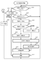
- the flowchart of centralized control processing which a power system control central unit performs.
- the power system control central device 1 as the “first control device” is a unit of measurement data from a plurality of sensors 3 as the “sensor devices” disposed in the power system.
- the power state of the power system is estimated based on the measurement data actually obtained.
- the power state can be estimated based on all the measurement data, or the power state can be estimated based on only some of the measurement data.
- the power system control central unit 1 receives measurement data transmitted from each sensor 3 that measures the power state of a specific position in the power system, and stores the measurement data in the storage unit 12.
- the power system control central unit 1 uses the measurement data to estimate and calculate the power state of the entire power system based on either the power flow calculation or the state estimation calculation method.
- the electric power system control central unit 1 stores the estimated electric power state in the storage unit 12 and uses the estimated electric power state to control the amount of control to be output by each electric power system controller 2 as the “second control device”.
- Calculate The power system control central unit 1 stores the calculated control amount in the storage unit 12 and uses it in the power system control device 2 using the measurement data, the power state, and the control amount stored in the storage unit 12 respectively. Parameters for the power state estimation model and parameters for the control amount calculation model are determined. The determined parameters are transmitted to the power system control device 2 and stored.
- the power system control central unit 1 creates, for each of the power system control devices 2, a power condition estimation model that each power system control device 2 uses to estimate the power condition, and each power system control device Send to 2 Furthermore, the power system control central unit 1 generates a control amount calculation model for calculating the control amount based on the estimated power state for each power system control device 2, and Send.
- the communication state between each power system control device 2 and the power system control central device 1 can be determined from the communication state between the power system control central device 1 and each sensor 3 using the same communication network.
- the centralized control mode As the “first control mode” is executed.
- the power system control central apparatus 1 estimates the power state of each of the predetermined points of the power system based on the measurement data actually acquired.
- the power system control central apparatus 1 calculates a control amount from the estimated power state, and transmits a control command including the calculated control amount to each power system control device 2.
- the power system control device 2 under the centralized control mode executes a predetermined control operation based on the control amount in the control command received from the power system control central device 1.
- the predetermined control operation differs depending on the type of power system control device 2.
- Each of the power system control devices 2 shifts from the centralized control mode to the distributed control mode as the “second control mode” when the communication state with the power system control central device 1 is deteriorated.
- the power system control device 2 controls its own device by inputting measurement data from a predetermined sensor among the sensors 3 to the power state estimation model received from the power system control central device 1. Estimate the power state to be done.
- the power system control device 2 under the distributed control mode inputs the power state estimated by the own device into the control amount calculation model received from the power system control central device 1, obtains the control amount, and realizes the control amount. To perform predetermined control operations.
- the distributed control mode is selected from the distributed control mode when the effective state preset in the power state estimation model has passed after a lapse of time while the communication state between each power system control device 2 and the power system control central apparatus 1 has deteriorated. Shift to "autonomous control mode" as control mode.
- the power system control device 2 under the autonomous control mode has measurement data from a predetermined sensor among the sensors 3, for example, a sensor (self-end sensor) directly associated with the own device, and the power stored in advance.
- the control amount is calculated based on the system data indicating the configuration of the system.
- the power system control device 2 executes a predetermined control operation according to the calculated control amount.
- the power system control central apparatus 1 can estimate the power state based on the measurement data actually acquired among the measurement data from the plurality of sensors 3. Therefore, even when the communication state between the sensor 3 and the central control 1 of the power system is bad, the power state can be estimated according to the communication state (communication speed, communication quality), and the reliability can be improved.
- communication between the power system control central apparatus 1 and the power system control device 2 is performed from among a plurality of control modes (central control mode, distributed control mode, autonomous control mode) prepared in advance. Based on the state, an appropriate control mode can be selected to control the state of the power system according to the selected control mode. Therefore, the power state can be appropriately controlled according to the communication state (communication speed, communication quality), and the reliability can be improved.
- control modes central control mode, distributed control mode, autonomous control mode
- a power system control system will be described with reference to FIGS. 1 to 13.
- a power system control system that monitors the communication state of the communication network 4 for controlling the power system, switches the control mode according to the communication state, and appropriately controls the power system control device 2 is described.
- the power system control central unit 1 the plurality of power system control devices 2a to 2c, and the plurality of sensors 3a to 3c are communicably connected via the communication network 4 .
- the power system control devices 2a to 2c will be referred to as the power system control device 2
- the sensors 3a to 3c will be referred to as the sensor 3.
- the power system control central apparatus 1 is configured as a computer system including, for example, an arithmetic processing unit, a storage device, a communication device (all not shown) and the like, and a computer program and data are stored in the storage device.
- the various functions described below are realized by the arithmetic processing unit (CPU) reading and executing a computer program.
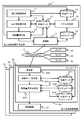
- the power system control central device 1 has a system data storage unit 10 for storing system data, a measurement data storage unit 12 for storing measurement data, and model data as a data storage function for storing data. And model data 16 for storing. Further, the power system control central apparatus 1 generates a communication state monitoring unit 11 that monitors the communication state, a power state estimation unit 13 that estimates the power state, a control amount calculation unit 14 that calculates the control amount, and a model. A model generation unit 15 and a transmission unit 17 for communicating with each power system control device 2 and each sensor 3 are provided.
- the data stored in the system data storage unit 10 is the system data
- the data stored in the measurement data storage unit 12 is the measurement data
- the data stored in the model data storage unit 16 is a model It may be called data 16 respectively.
- the power system control device 2 includes a controller 20 and a control unit 21.
- the controller 20 has, as a data storage function for storing data, a system data storage unit 201 for storing system data, a model data storage unit 202 for storing model data, and a measurement data storage unit 205 for storing measurement data.
- the controller 20 corresponds to the receiving unit 200 for communicating with the power system control central apparatus 1 and the sensor 3, the control mode determining unit 203 for determining any one of a plurality of control modes, and the control mode.
- a control amount calculation determination unit 204 that calculates a control amount.
- data stored in the system data storage unit 201 is measured as the system data 201
- data stored in the model data storage unit 202 is measured as the model data 202
- data stored in the measurement data storage unit 205 are measured. It may be called data 205, respectively.
- the sensor 3 will be described.
- the sensor 3 is a device that measures the amount of power state at the installation position.
- the power state quantity measured by the sensor 3 is transmitted to the communication state monitoring unit 11 of the power system control central apparatus 1 and the receiving unit 200 of the power system control device 2 via the communication network 4.
- data of the amount of power state measured by the sensor 3 is referred to as sensor data.
- the communication state monitoring unit 11 of the power system control central apparatus 1 stores the received sensor data as a part of the measurement data 12.
- the receiver 200 of the power system control device 2 stores the received sensor data as part of the measurement data 205.
- the state of accumulating sensor data will be described later with reference to FIG.
- the communication network 4 is a communication network connecting the power system control central unit 1, the power system control device 2, and the sensor 3.
- the respective devices 1, 2 and 3 mutually transmit and receive various information such as a control command or sensor data using the communication network 4.
- the communication medium may be, for example, a public line such as a telephone line, a local line such as Ethernet (registered trademark), a dedicated communication line, a wired line such as a power line carrier communication line, or a mobile phone communication network, PHS, for business use It may be wireless, such as wireless, satellite line, wireless LAN, ZigBee (registered trademark), or the like.
- system control central unit 1 is demonstrated.
- the grid data 10 is data related to the configuration of the power grid network.
- the system data 10 will be described using the examples shown in FIGS.
- FIG. 2 shows an outline of a power system network.
- the power system network is roughly divided into nodes 31 and branches 32, each of which has attribute data.
- the nodes 31a to 31g are referred to as the node 31 when not particularly distinguished, and the branches 32a to 32f are referred to as the branch 32 when not particularly distinguished.
- the node 31a is a substation, to which the sensor 3a and the power grid control device 2a are connected.
- the node 31 b is a utility pole on which a pole transformer is installed, to which the sensor 3 b is connected.
- the node 31c is a utility pole on which a pole transformer is installed, but no sensor is installed there.
- the node 31 d indicates a load or a power supply such as a customer or a distributed power source, to which the sensor 3 c and the power grid control device 2 b are connected.
- the node 31 e is a utility pole on which a pole transformer is installed, and no sensor is installed there.
- the node 31 f is a utility pole on which a pole transformer is installed, and a sensor 3 d is installed there.
- the last node 31g indicates a load or power supply such as a customer or a distributed power source, to which a sensor 3e and a power system control device 2c are connected.
- node management information T10 for managing the configuration of the node 31 will be described with reference to FIG.
- the node management information T10 constitutes a part of the system data 10.
- the node management information T10 identifies, for example, information C100 identifying a node, information C101 indicating a presence or absence of a substation (substation flag), information C102 indicating a presence or absence of a pole transformer (pole transformer flag), and a sensor Information C103, information C104 identifying a control device, measurement value of sensor (value of sensor data) C105, and state estimated value C106 are associated with each other and managed. Other items than the illustrated management items may be added, or the illustrated management information may be divided into a plurality of management information, and the divided management information may be associated with each other by a link or a pointer. The same can be said for the other management information described later as well as the node management information T10.
- Each sensor 3 can measure, for example, the active power P, the reactive power Q, the voltage V, and the like according to the type and role of each sensor 3 and output sensor data.
- the state estimated value C106 is a value estimated using all or part of the sensor data from each sensor 3. In the nodes 31c and 31e where the sensor 3 is not installed, the power state of the node is estimated and stored in the node management information T10.
- the branch 32 will be described.
- the branch 32 is a path between nodes and specifically, a transmission line or a distribution line.
- Each branch 32 has a resistance R and a reactance X as its impedance.
- the branch 32a is a section in which the start point node is 31a and the end point node is 31b.
- the start point of the branch 32b is the node 31b, and the end point is the node 31c.
- the start point of the branch 32c is the node 31c, and the end point is the node 31d.
- the start point of the branch 32d is the node 31d, and the end point is the node 31e.
- the start point of the branch 32e is the node 31e, and the end point is the node 31f.
- the start point of the branch 32f is the node 31f, and the end point is the node 31g.
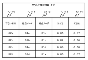
- Branch management information T11 for managing the configuration of the branch 32 will be described with reference to FIG.
- the branch management information T11 constitutes a part of the system data 10.
- the branch management information T11 manages information C110 identifying the branch 32, information C111 indicating a start point node, information C112 indicating an end point node, a resistance value C113, and a reactance C114 in association with one another.
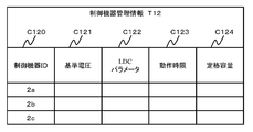
- Control device management information T12 for managing the power system control device 2 will be described with reference to FIG.
- the control device management information T12 constitutes a part of the system data 10.
- the control device management information T12 manages, for example, information C120 for identifying the power system control device 2, a reference voltage C121, an LDC (Line Drop Compensator) parameter C122, an operation time limit C123, a rated capacity C124, and the like.
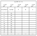
- the communication state monitoring unit 11 collects sensor data with a time stamp from each sensor 3 at a predetermined constant monitoring cycle Tm, and stores the collected sensor data with a time stamp as measurement data 12 in a memory or the like.
- the sensor data T13 collected and stored periodically will be described with reference to FIG.
- the sensor data T13 includes a time stamp C130, information C131 for identifying the sensor 3, a measured value C132 (active power), C133 (reactive power), and C134 (voltage) as a part of the measurement data 12 It is memorized.
- the measured values of the power state may include, for example, current, power factor, and power flow direction (current direction).
- the communication state monitoring unit 11 determines the soundness of the communication state with the power system control central apparatus 1 for each sensor 3 based on the collected time stamped sensor data. An example of a method of determining the soundness of the communication state will be described.
- the time stamp of the sensor data (the latest received sensor data) obtained previously and the current time
- the difference is compared to a predetermined time period Ta. If the difference between the current time and the time stamp of the latest sensor data exceeds the predetermined time period Ta (current time-time stamp of latest sensor data> Ta), it is determined that the soundness of the communication state is degraded be able to. As the difference between the current time and the time stamp of the latest sensor data increases, it can be determined that the soundness of the communication state is degraded.
- the causes of the decrease in the soundness of the communication state include the cause of the communication network 4 itself and the cause of the sensor 3 itself.
- a cause of the communication network 4 itself for example, communication congestion, radio interference by electromagnetic waves from obstacles or electronic devices, disconnection may be considered.
- a cause of sensor 3 itself a failure of sensor 3, temporary stop of processing by overload, etc. can be considered, for example. Therefore, by determining the soundness of the communication state between the sensor 3 and the central control 1 of the power system control, it can be determined including whether the sensor 3 is operating normally.
- the sensor data includes the measured power state quantities (active power, reactive power, voltage, etc.).
- the sensor data is periodically transmitted from the sensor 3 to the communication state monitoring unit 11 via the communication network 4 and time-stamped and accumulated.
- the transmission period of sensor data is determined in advance for each power system, for example, in consideration of the specifications of the communication line, the number of communication devices, the target performance, and the like.
- the transmission cycle is set to, for example, a value such as one minute, three minutes, ten minutes, thirty minutes, sixty minutes, and so on.
- the measurement data 12 will be described.
- the measurement data 12 besides the sensor data, the estimated value of the power state estimated by the power state estimation unit 13 and the time stamp thereof, and the control amount of each power system control device 2 calculated by the control amount calculation unit 14 And a time stamp as control timing.
- the power state estimation unit 13 determines the observability in the power state estimation calculation according to the number of sensor data (hereinafter, the number of normal sensor data) for which the communication state monitoring unit 11 determines that the communication state is normal.
- the total number of power states of the node 31 and the branch 32 of the target power system is Nd
- the ratio (Nn / Nd) of the number Nn of normal sensor data to the total number Nd is calculated. If the ratio (Nn / Nd) is equal to or greater than a predetermined value, it can be determined as observable, otherwise it can be determined as unobservable.
- the power state (voltage, active power, reactive power, etc.) of the entire power system is estimated and calculated using the sensor data determined to be normal and the grid data 10 by different methods according to the above observability. . If it is determined to be observable, state estimation calculation including tidal current calculation is performed, otherwise, only tidal current calculation is performed.
- the power state of each node and each branch can be determined by setting equations (power equations) for active power and reactive power for each node and each branch, and solving using sensor data.
- the state estimation calculation an initial value is given for the power state of each node, and the sum of the squares of the deviation between the estimated value and the measured value regarding the power state obtained by the power flow calculation based thereon is minimized.
- the solution for the power state is iteratively found, and finally an estimate of the power state at any point in the power system is obtained.
- a time stamp is added to the estimated value of the power state obtained in this manner, and accumulated as measurement data 12. The method of estimating the power state will be described later in other embodiments.
- the power state estimated by the power state estimation unit 13 of the power system control central apparatus 1 corresponds to the “first power state”.
- the control amount calculation unit 14 uses the power state estimated by the power state estimation unit 13 to calculate a control amount as a “first control amount” to be output by each power system control device 2. In this operation, for example, a sum of squares of deviations of measured voltages from target voltages at specific plural points is used as an objective function. Then, the optimal control amount of each control device is calculated so as to minimize the objective function.
- the model generation unit 15 will be described.
- the model generation unit 15 generates model data (a parameter of an arithmetic expression) for use in estimating the power state of each power system control device 2 or calculating the control amount according to the estimated power state. Do.
- the model generation unit 15 uses various data accumulated in the measurement data 12 as teacher data, and identifies parameters of an operation model to be used by the controller 20 of the power system control device 2.
- the generated operation models are a power state estimation model and a control amount calculation model.
- Each of these models may be either a linear model or a non-linear model.
- a linear model is described as an example.
- the input to the power state estimation model is the power state measured by each sensor 3.
- the output from the power state estimation model is the power state estimated by the power state estimation unit 13 for each node (or each branch) of the power system.
- Each coefficient parameter is identified by the least square method using input data and output data regarding a plurality of time stamps as a linear model shown in the following Equation 1.
- Sn represents active power (real number component) and reactive power (imaginary number component) at an arbitrary node n.
- Pk and Qk indicate the active power (real number component) and the reactive power (imaginary number component) measured by the sensor (sensor node k), respectively.
- a and b are coefficient parameters of the power state estimation model.
- control amount calculation model The input of the control amount calculation model is the power state of each node estimated by the power state estimation unit 13.
- the output of the control amount calculation model is the control amount of each power system control device 2 calculated by the control amount calculation unit 14.
- each coefficient parameter is identified by the least square method using input data and output data regarding a plurality of time stamps as a linear model shown in the following Equation 2.
- the control amount Cj is, for example, an output at the power system control device node j (tap ratio of LRT / SVR (transformation ratio), SVC, switched capacitor, reactive power of PCS (Power Conditioning System with battery)) .
- LRT is an abbreviation for Load Ratio Transformer.
- Pm, Qm, and Vm are the estimated active power (the real component of the Sm) and the estimated reactive power (the imaginary component of the Sm) at the monitoring node m, respectively.
- c and d are coefficient parameters of the control amount calculation model. Note that Pm, Qm, and Vm may be used if there are actual measurement values (power state values of sensor data) measured by the sensor 3.
- the control amount to be output by each power system control device 2 is easily calculated. be able to.
- each power system control device 2 has a power state estimation model and a control amount calculation model, even if the communication state of the communication network 4 is not normal, it is appropriate to use sensor data at its own end. Control can be performed.
- the model data 16 will be described.
- the model data 16 are parameters a and b constituting the power state estimation model shown in Formula 1, and parameters c and d constituting the control amount calculation model shown in Formula 2.
- target nodes sensor node k and monitoring node m
- target nodes sensor node k and monitoring node m
- estimation calculation may be performed using only sensor data of some of the sensors 3.
- the node j of the power system control device 2 uses only its own end node j. That is, each power grid control device 2 does not refer to sensor data of sensors 3 other than the self-end node.
- the sensor of the own end node is a sensor directly associated with the power system control device 2, that is, a sensor provided at a node common to the node of the power system control device 2.
- the self-end node of the power system control device 2a is the node 31a, and the sensor of the self-end node is the sensor 3a.
- the self-end node of the power system control device 2b is the node 31d, and the sensor of the self-end node is the sensor 3c.
- the self-end node of the power system control device 2c is the node 31g, and the sensor of the self-end node is the sensor 3e.
- the power system control device 2 If the sensor data to be referred to by the power system control device 2 is limited to the sensor data from the sensor 3 of the own end node, even if the soundness of the communication state is lost, the power system control device 2 It can be used to estimate the power state of the power system.
- FIG. 7 shows an outline of the case where the power state estimation model and the control amount calculation model are created as linear models.
- the input on the horizontal axis is sensor data (the value of the power state measured by the sensor 3), and the output on the vertical axis is the power state estimation It is a value.
- the input on the horizontal axis is the estimated value of the power state
- the output on the vertical axis is the estimated control amount
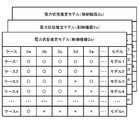
- FIG. 8 is an explanatory view showing how a power state estimation model is generated for each combination of sensor data that can be acquired.
- the power state estimation unit 13 of the power system control central apparatus 1 generates a power state estimation model according to the acquisition state of sensor data from each of the sensors 3a to 3e.
- the first case is a case where sensor data can be normally acquired from all the sensors 3a to 3e.
- sensor data from all the sensors 3a to 3e are used to generate a power state estimation model.
- the second case is a case where sensor data can be acquired from other sensors 3a to 3d other than the sensor 3e among the sensors 3a to 3e, and only sensor data from the sensor 3e can not be acquired.
- the power state estimation model is generated based only on the acquired sensor data (sensor data of the sensors 3a to 3d).
- the third case is a case where sensor data can be acquired from other sensors 3a to 3c, 3e other than the sensor 3d among the sensors 3a to 3e, and only sensor data from the sensor 3d can not be acquired.
- a power state estimation model is generated based only on sensor data of the sensors 3a to 3c and 3e.
- a power state estimation model is generated for each combination of sensor data that can be acquired normally.
- a power state estimation model is generated also in the case where only one sensor data can be acquired (case n). If sensor data from the sensor of the self-end node of the power system control device 2 can be acquired, a power state estimation model for the power system control device 2 can be generated. If power system control device 2 is configured to be able to acquire sensor data from sensors of distant nodes other than the sensor of its own end node, a power state estimation model based only on sensor data from sensors of distant nodes Is also generated.
- the power state estimation model is prepared for each of the power system control devices and for each combination of sensor data.
- the power state estimation unit 13 determines the power state estimation model corresponding to the combination of the acquired sensor data. It can be used to estimate the power state.
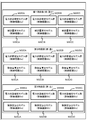
- FIG. 9 shows how a power state estimation model is generated according to the time zone.
- the power supply and demand conditions differ depending on, for example, weather and temperature, they also differ depending on the time zone such as morning, daytime and night.
- the time zone such as morning, daytime and night.
- the demand for electricity increases due to the preparation of meals in the morning and in the evening.
- Electricity demand declines as daytime is likely to be absent.
- the amount of solar power generation in the morning and evening is small, and the amount of power generation in the daytime is large.
- the power supply and demand situation also differs depending on the characteristics of consumers such as private residences, factories and commercial facilities, but the difference also depends on the time zone.
- the time of day is divided into a plurality of time zones, such as a first time zone (morning and evening), a second time zone (daytime), and a third time zone (night).
- a power state estimation model group and a control amount calculation model are generated.
- a plurality of power state estimation models for each power system control device are generated in accordance with the combination of the acquired sensor data.
- power state estimation model group M2EA and control amount calculation model M2CA are generated.
- power state estimation model group M2EB and control amount calculation model M2CB are generated.
- power state estimation model group M2EC and control amount calculation model M2CC are generated.
- the models M2EA, M2EB, M2EC and M2CA, M2CB, M2CC of the power grid control devices 2a to 2c are generated for each time zone.
- the power state estimation unit 13 of the power system control central apparatus 1 selects one model that matches the combination of the acquired sensor data from the power state estimation model group of the time zone to which the current time belongs, and selects the power state.
- the transmitting unit 17 has a function of transmitting any of the following data to each power system control device 2 via the communication network 4.
- the first transmission data is a control amount to be output by each power system control device 2 calculated by the control amount calculation unit 14.
- the second transmission data is model data 16 (a power state estimation model and parameters constituting a control amount calculation model) generated by the model generation unit 15.
- the third transmission data is system data 10. The above three types of data are transmitted at a predetermined timing after being updated, so that the transmission period also differs depending on the update period of each data.
- the power system control device 2 includes a controller 20 that determines a control amount, and a control unit 21 that executes a predetermined control operation.
- Examples of the power system control device 2 include devices for mainly controlling the voltage among the states of the power system, such as LRT, SVR, SVC, switched capacitor, and PCS with battery.
- the receiver 200 has a function of receiving data transmitted from the transmitter 17 of the power system control central apparatus 1. Among the received data, the control amount to be realized by the power system control device 2 is transmitted to the control mode determination unit 203.
- the received model data is stored as a model data 202 used by the controller 20 in a storage device (hard disk drive, flash memory, optical disk, etc.).
- the received system data is stored in the storage device as the system data 201 used by the controller 20.
- the receiving unit 200 also has a function of receiving sensor data from all or a predetermined part of the sensors 3 and storing the sensor data as measurement data 205.
- the grid data 201, the model data 202, and the measurement data 205 are the same as the grid data 10, the model data 16, and the measurement data 12 stored in the power grid control central device 1. However, only sensor data from a sensor (self-end node sensor) provided at the self-end node of power system control device 2 may be accumulated as measurement data 205.
- the control mode determination unit 203 has a function of determining operation in any one of a centralized control mode, a distributed control mode, and an autonomous control mode prepared in advance as a control mode at a predetermined cycle.
- the control mode determination method will be described with reference to FIG. For example, when the difference Td between the time stamp of the control amount data received last time from the transmission unit 17 by the reception unit 200 and the current time is equal to or more than a first predetermined time T1 set in advance (Td T T1), the power system control device 2 shifts to the distributed control mode.
- the first predetermined time T1 is set to a predetermined control command cycle Tc or more (T1 Tc Tc).
- the power system control The device 2 executes a predetermined control operation based on the centralized control mode.
- the power system control device 2 uses the power state estimation model received from the power system control central device 1 and the power state of the power system based on predetermined sensor data (for example, a sensor of the own end node). Estimate Furthermore, the power system control device 2 calculates a control amount (second control amount) based on the estimated power state and the received control amount calculation model, and executes a predetermined control operation (performs a predetermined control output) ).
- predetermined sensor data for example, a sensor of the own end node.
- the power system control device 2 can estimate the power state based on the power state estimation model and perform appropriate control. If the time zone is changed, the power state estimation model is switched according to the time zone and the distributed control mode is continued.
- the distributed control mode in which control is performed after estimating the power state of the power system is different from an autonomous control mode described later in which control is performed so as to simply eliminate the deviation from the target value.
- the power system control device 2 operating under the distributed control mode can control the power state with relatively high accuracy.
- the configuration of the power system may be changed, for example, as a new distributed power supply is connected to the power system or equipment of a customer is discarded.
- the change in power system configuration also affects the estimation accuracy of the power state, and the appropriate control amount also changes.
- a period T2 that can be effectively used is set in advance.
- the power system The control device 2 shifts from the distributed control mode to the autonomous control mode.
- the valid period T2 can also be referred to as a second predetermined time, and is set longer than the first predetermined time T1 (T2> T1TTc).
- the power system control device 2 under the autonomous control mode performs control so as to eliminate the deviation between the target value and the actual measurement value based on the sensor data from the sensor 3 of the own end node. In the autonomous control mode, control is performed based on only the power state of the own end node, which is different from the distributed control mode in which the power state of the entire power system is estimated and controlled.
- the power system control central apparatus 1 transmits the control amount calculated based on each sensor data to each power system control device 2 in a control cycle Tc such as several seconds to several minutes. If the communication state deteriorates and the control amount can not be received after waiting for a predetermined time T1 set to several minutes, the power system control device 2 shifts from the central control mode to the distributed control mode.
- the distributed control mode is shifted to the autonomous control mode.
- the effective period T2 of the power state estimation model may be defined as an elapsed time after it is created, or may be defined as a date and time such as "effective until June 1, 2012", for example. .
- the above specific numerical values are merely examples for understanding, and the present invention is not limited to the above numerical values.
- the mode shifts from the distributed control mode to the central control mode.
- the central control mode may be immediately shifted to when the control amount is received.
- the distributed control mode is continued until a new control amount is received, and the difference Td between the time when the new control amount is received and the time when the previous control amount is received is less than the first predetermined time T1. In this case, the distributed control mode may shift to the centralized control mode.
- the control mode may immediately shift to the centralized control mode. Alternatively, wait until a new control amount is received, and shift from the autonomous control mode to the centralized control mode when the difference between the previous control amount reception time and the current control amount reception time is less than the first predetermined time T1. May be
- the control amount calculation determination unit 204 has a function of calculating or determining the control amount output from the own device 2 (the power system control device) according to the control mode determined by the control mode determination unit 203.
- the control amount calculation determination unit 204 determines the use of the control amount data itself received from the power system control central device 1. In the case of the distributed control mode, the control amount calculation determination unit 204 determines the above based on the power state estimation model and the control amount calculation model defined by the model data 202 received from the power system control central device 1 and predetermined sensor data. The calculations shown in Formula 1 and Formula 2 are executed to determine the control amount. In the case of the autonomous control mode, the control amount calculation determination unit 204 determines the control amount according to a predetermined method determined in advance based on the control parameters of each power grid control device 2 included in the grid data 201 and the measurement data 205. .
- the control amount to be output by the own device 2 is calculated and determined based on the SVC, the switched capacitor, and the constant voltage control in the PCS with battery.
- the control unit 21 has a function of performing control output as a “predetermined control operation” in accordance with the control amount determined by the control amount calculation determination unit 204.
- the control output is a tap ratio (transformation ratio), and a tap map (a list in which tap numbers corresponding to the transformation ratio are described) included in the control parameter is referred to.
- the tap is switched to the corresponding tap number. If the tap number has already been reached, the switching operation is not performed.
- control outputs When the control unit 21 is an SVC, a switched capacitor, or a PCS with a battery, there are two types of control outputs, that is, an output of reactive power or a target voltage.
- the control output When the control output is a reactive power output, it is output as "lead 50 kvar" or "delay 30 kvar”.
- control unit 21 When the control unit 21 is an SVC, a switched capacitor, a PCS with a battery, etc., the output operation is performed accordingly. If the control output is the target voltage, the control unit 21 first monitors the difference between the voltage at the installation point of the power system control device 2 and the target voltage. Then, the control unit 21 corrects the target voltage by, for example, PI control (proportional control, integral control) using the difference. The control unit 21 determines reactive power to match the corrected target voltage in consideration of reactance between the installation point of the power system control device 2 and the inverter (capacitor), and outputs according to the reactive power Do the action.
- PI control proportional control, integral control
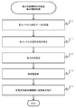
- the communication state monitoring unit 11 collects sensor data with a time stamp from each of the sensors 3 in a predetermined constant monitoring cycle Tm, and accumulates it as measurement data 12 (S10). The communication state monitoring unit 11 determines the soundness (whether normal or not) of the communication state with the power system control central apparatus 1 for each sensor (S11).
- the power state estimation unit 13 determines the observability in the power state estimation calculation according to the number of sensor data whose communication state is determined to be normal (hereinafter, the number of normal sensor data).
- the power state estimation unit 13 uses the sensor data of the sensor determined to be normal and the grid data 10 by different methods according to the observability, and the power state (voltage, active power, reactive power, etc.) of the entire power grid Make an estimate calculation of If it is determined to be observable, state estimation calculation including tidal current calculation is performed, otherwise, only tidal current calculation is performed. Thereby, an estimated value of the power state at an arbitrary point of the power system is obtained (S12).
- the control amount calculation unit 14 calculates the control amount to be output by each power system control device 2 using the estimated power state (S13). Finally, the transmission unit 17 transmits the calculated control amount as a command value to each power grid control device 2 through the communication network 4 (S14).
- the power system control central unit 1 determines the soundness of the sensor data from each sensor 3 and performs appropriate power state estimation calculation according to the soundness, and based on that, each power system control device A function to transmit an optimal control command value to 2 is provided.
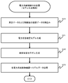
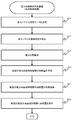
- the model generation unit 15 determines the power state measured by the sensor 3 among the data accumulated as the measurement data 12, the power state of each node and each branch estimated by the power state estimation unit 13, and the control amount.
- the control amount of each power grid control device 2 calculated by the calculation unit 14 is read to be used as teacher data (S20).
- the model generation unit 15 generates a power state estimation model using the power states actually measured by the sensor 3 and the power states of each node and each branch estimated by the power state estimation unit 13 (S21). As described above, when the power state estimation model is generated as a linear model, the model generation unit 15 identifies each of the coefficient parameters a and b by the least square method according to the above-described Equation 1 (S21).
- the model generation unit 15 uses the power state of each node and each branch estimated by the power state estimation unit 13 and the control amount of each power system control device 2 calculated by the control amount calculation unit 14. Generate a control amount calculation model. As described above, in the example of the linear model, each coefficient parameter c, d is determined by the least square method according to Equation 2 (S22).
- data (coefficient parameters) of the calculation model generated for each of the power system control devices 2 is packaged in a predetermined combination.
- the power state estimation model is a combination of those for the node x and the node y
- the control amount calculation model is that for the node j.
- the data of each operation model packaged in this way is transmitted to each power system control device 2 via the communication network 4 (S23).
- the power system control central unit 1 generates the power state estimation model and the control amount calculation model from the measurement data, and sends model data (control parameters) for determining these models to each power system control device 2 It has a function to send.
- the power state estimation model is determined by two parameters a and b, and the control amount calculation model is also determined by two parameters c and d. Therefore, the data size of each model can be reduced. Since the size of each model data can be reduced, an increase in communication load can be suppressed even if a plurality of model data are periodically transmitted to each power system control device 2. Therefore, even when the communication speed of the communication network 4 is slow, model data with a small data size can be transmitted normally. Further, since each arithmetic model can be used with a small number of parameters, even when the performance of the arithmetic processing unit (CPU) of the power system control device 2 is low, the power state can be estimated to obtain an appropriate control amount. Conversely, it is not necessary to mount a high-performance arithmetic processing device or the like on the power system control device 2, and the manufacturing cost can be reduced.
- CPU arithmetic processing unit
- the reception unit 200 confirms the presence or absence of unprocessed reception data (S30). If there is unprocessed received data, the difference between the time stamp of the unprocessed received data and the current time is determined. If the difference Td between the time stamp of the unprocessed reception data and the current time is smaller than the first predetermined time T1, the process proceeds to step S31, otherwise the process proceeds to step S33. Also when there is no unprocessed received data, the process proceeds to step S33.
- the receiving unit 200 determines the type (S31). If the unprocessed reception data is a control amount, it is determined that the centralized control mode is set, and the process proceeds to step S40. When the unprocessed reception data is other than the control amount (ie, in the case of arithmetic model data, sensor data, and system data), the receiving unit 200 proceeds to step S32. In step S32, the reception unit 200 stores each data in a predetermined storage device among the storage devices 201, 202, and 205, and returns to step S30.
- control mode determining unit 203 determines whether the current time is the timing to determine the control mode (S33).
- step S33 the control mode determination unit 203 determines whether the difference Tdt between the previous control mode determination timing and the current time is equal to or greater than a timing determination time Tt1 set in advance. If the elapsed time Tdt from the previous determination time is equal to or greater than the predetermined timing determination time Tt1 (TdtTTt1), it is determined Yes and proceeds to step S34, otherwise it is determined No and only the predetermined waiting time Tw After waiting, it returns to S30. Alternatively, the process may return to step S30 without waiting for the passage of time Tw.
- step S34 the control mode determination unit 203 determines a control mode. As described in FIG. 10, when the difference Td between the time stamp of the control amount data (the latest control amount data) received last time by the receiving unit 200 and the current time is equal to or longer than the predetermined time T1, as described in FIG. The distributed control mode is selected, and the process proceeds to step S36. On the other hand, when the transition to the distributed control mode has already progressed to the distributed control mode, the control mode determination unit 203 selects the autonomous control mode when the elapsed time Ts from the transition to the distributed control mode becomes equal to or longer than the predetermined time T2. The process moves to step S39.
- the control amount calculation determination unit 204 determines the type of the determined control mode (S35). When it is determined that the determined control mode is the distributed control mode, the control amount calculation determination unit 204 reads the model data 202 (S36). Furthermore, the control amount calculation determination unit 204 reads the measurement data 205 (S37), and estimates the power state of the power system based on the power state estimation model and the sensor data (S38). In step S38, the power state can be estimated using the power estimation model for the time zone corresponding to the current time, which is the power estimation model corresponding to the combination of the sensor data successfully acquired.
- the control amount calculation determination unit 204 calculates the control amount to be realized by the own end node based on the estimated power state and the control amount calculation model (S40).
- the control amount calculated by the control amount calculation determination unit 204 is sent from the controller 20 to the control unit 21, and the control unit 21 executes a predetermined control operation (S41).
- the control amount calculation determination unit 204 reads the system data 201 (S39), and further reads the measurement data 205 (S37).
- the control amount calculation determination unit 204 includes a control parameter (FIG. 5) included in the system data 201, a control method (LDC method for LRT / SVR, SVC, switched capacitor, constant voltage control for PCS with battery, etc.) The control amount is calculated based on the sensor data of the own end node.
- control amount calculated under the autonomous control mode is transmitted from the controller 20 to the control unit 21.
- the control unit 21 executes a predetermined control operation according to the calculated control amount (S41).
- the power system control central apparatus 1 generates a power state estimation model according to the combination of sensor data that can be acquired normally. For this reason, even when the state of the communication network 4 is bad and sensor data from all the sensors 3 can not be received, the control state can be calculated by estimating the power state. Therefore, the power system control system according to the present embodiment can estimate the power state according to the communication environment even in an area where the communication environment is bad, and can appropriately control the power state of the power system.
- the power system control device 2 can select any one control mode from a plurality of control modes in accordance with the communication state. Therefore, the power system control device 2 can operate appropriately according to the state of the communication network 4.
- the soundness of the communication state of the communication network 4 is determined based on the time stamp of the received data and the current time, and a control mode corresponding to the communication state is selected. Therefore, the power system control device 2 can evaluate the communication state relatively easily and accurately, and can select an appropriate control mode.
- the sensor data which is the measured value of the sensor 3, the history of the estimated value of the power state, and the history of the calculated control amount are accumulated and managed as measurement data, and the power state is calculated based on the measured data.
- the power state estimation model generated by the power system control central apparatus 1 and model data for specifying a control amount calculation model are configured as a set of parameters. Therefore, the size of the model data can be reduced, and the load on the communication network 4 can be suppressed even when the power system control central device 1 distributes the model data to the plurality of power system control devices 2. Therefore, the power system control system according to the present embodiment can appropriately control the power system even in an environment where communication speed is low and communication quality is unstable.
- the power system control device 2 of this embodiment controls in the central control mode when the communication state is healthy, controls in the distributed control mode when the communication state is deteriorated, and the effective period of the power state estimation model is over. Controls in the autonomous control mode. Therefore, the power state can be controlled according to the degree of soundness of the communication state.
- the effective period is set in the power state estimation model used in the distributed control mode, and the power state estimation model whose effective period has passed is not used, and the transition to the autonomous control mode is made. Therefore, it is possible to suppress the execution of the distributed control far from the change in the power demand / supply state and the change in the configuration of the power system, and to improve the reliability of the system.
- a second embodiment will be described with reference to FIGS. 14 to 16.
- the following embodiments including the present embodiment correspond to modifications of the first embodiment, and therefore, differences from the first embodiment will be mainly described.
- the power system control device 2 that can be managed by the power system control central device 1 and the power system control device 5 that can not be directly managed by the power system control central device 1 coexist in the same power system.
- the power system control device 2 that can be managed by the power system control central device 1
- the power system control device 5 that can not be directly managed by the power system control central device 1
- FIG. 14 is an overall configuration diagram of a power system control system according to the present embodiment.
- the power system control central unit 1, the plurality of power system control devices 2, and the plurality of sensors 3 are connected via the communication network 4.
- a plurality of power system control devices 5a to 5c not connected to the communication network 4 are disposed in the power system targeted by the present system.
- the control devices 5a to 5c are not particularly distinguished from one another, they are called the power system control device 5.
- the power system control device 2 described in the first embodiment is referred to as the new power system control device 2 and the power system control device not connected to the communication network 4 is the old power system It may be called control device 5.
- the power system control device 5 dedicated to autonomous control will be described.
- the power system control device 5 includes a controller 50 and a control unit 51.
- the controller 50 includes a receiving unit 500, a system data storage unit 501, a control amount calculation determination unit 502, and a measurement data storage unit 503.
- the data stored in the system data storage unit 501 may be referred to as the system data 501
- the data stored in the measurement data storage unit 503 may be referred to as the measurement data 503.
- the receiving unit 500 implements part of the functions of the receiving unit 200 described above.
- the receiving unit 500 has a function of receiving sensor data from the sensor 3 provided in the self-end node, and storing the received sensor data as measurement data 503.
- the system data 501 is a control parameter of the device 5 and is stored in advance in a storage device such as a memory. Since the control method differs depending on the type of power system control device 5, the control parameter also differs according to the control method. For example, in the case of LRT / SVR, the LDC method is used, and in the case of an SVC, a switched capacitor, or a PCS with a battery, a method such as constant voltage control is used. Control parameters corresponding to each method are stored as system data 501.
- the control amount calculation determination unit 502 has a function of inputting measurement data to a control method (control parameter), calculating and determining a control amount to be output by the own device 5.
- the control unit 51 is the same as the control unit 21 of the power system control device 2 and has a function of performing a predetermined control operation according to the control amount determined by the control amount calculation determination unit 502.
- the power system to be controlled by the power system control system of this embodiment includes the power system control device 5 dedicated to the autonomous control mode, which can not be directly controlled from the power system control central apparatus 1. There is. Therefore, it is preferable that the power system control central apparatus 1 calculate the control amount and the like in consideration of the control operation executed by the power system control device 5 dedicated to the autonomous control. Therefore, the power system control central apparatus 1 of the present embodiment adds an improvement to the control amount calculation unit 14a.
- the receiving unit 500 determines whether received data has been received from the sensor of the self-end node (abbreviated as self-end sensor in FIG. 15) (S50). If there is unprocessed reception data, the reception unit 500 determines Yes if the difference between the time stamp and the current time is equal to or less than a predetermined time, and stores the unprocessed reception data in the storage device (S51) .
- the control amount calculation determining unit 502 determines whether the current time is a predetermined control timing at which control should be performed (S52). In step S52, the control amount calculation determining unit 502 determines whether an elapsed time from the previous control mode determination timing is a predetermined time or more. If the elapsed time from the previous determination timing is equal to or longer than the predetermined time, the determination is Yes and the process proceeds to step S53. If not, the determination is No and the process returns to S50 after waiting for a predetermined waiting time.
- the control amount calculation determination unit 502 reads the system data 501 (S53), then reads the measurement data 503 (S54), and calculates the control amount to be output (S55).
- the calculation method is the same as in the case of the autonomous control mode described in the first embodiment. That is, the control data is input to the control parameter (included in the system data 501) and the control method (LDC method in LRT / SVR, SVC, switched capacitor, constant voltage control in PCS with battery, etc.) calculate.
- the control amount calculated in this manner is transmitted to the control unit 51.
- the control unit 51 executes a predetermined control operation in accordance with the control amount calculated in step S55 (S56).
- the old power system control device 5 has a function of performing control amount calculation under the autonomous control mode and performing control output.
- the control amount computing unit 14 of the power system control central unit 1 calculates the control amount of the power system control devices 5
- the control amount is It can not be transmitted to the grid control device 5.
- the power system control device 5 calculates the same control amount as the control amount calculated by the power system control central device 1, and operates according to the control amount.
- the power system control device 5 outputs using the control method (control parameter) of the power system control device 5 and the power state estimated by the power state estimation unit 13. Predict the amount of control that will be done.
- control amount prediction process the same calculation process as the control amount calculation determination unit 502 of the power system control device 5 may be performed.
- the control amount calculation determination unit 502 temporarily determines the predicted control amount of each of the power system control devices 5 and, similarly to the control amount calculation unit 14 of the first embodiment, an objective function (for example, a voltage from each target voltage
- an objective function for example, a voltage from each target voltage
- the control amount to be output by each of the power system control devices 2 is calculated such that the sum of squares of deviations of the power control device 2) is minimized.
- Control amount calculation determination unit 502 performs power state estimation calculation based on the calculated control amount of each power system control device 2, and the control output by each power system control device 5 based on the obtained power state Predict the quantity again. Then, the control amount calculation determination unit 502 calculates again the control amount to be output by each power system control device 2 so that the objective function is minimized.
- control amount calculation determination unit 502 converges the change amounts of the control amounts of the control amount prediction processing of the old power system control device 5 and the optimum control amount calculation processing of the new type power system control device 2. Repeat until.
- the control amount calculation determination unit 502 adds a time stamp to the control amount of each power system control device 2 finally obtained, and accumulates it as measurement data 12. In addition, the control amount finally obtained is transmitted from the transmission unit 17 to each of the power system control devices 2.
- Steps S60 to S62 in FIG. 16 are the same processes as steps S10 to S12 in the flowchart of FIG.
- control amount calculation unit 14a uses the power state estimated by the power state estimation unit 13 based on the control method (control parameter) of the power system control device 5 to control each power system.
- the control amount output from the device 5 is predicted (S63).
- step S63 the control amount calculation unit 14a temporarily determines the predicted control amount of each power grid control device 5, and calculates the control amount that each power grid control device 2 should output so as to minimize the objective function. . Then, based on the calculated control amounts of the power system control devices 2, the control amount calculation unit 14a performs the power state estimation calculation and controls the power system control devices 5 to output based on the power states obtained again. Predict the quantity again.
- the control amount calculation unit 14a calculates again the control amount to be output by each power system control device 2 so that the objective function is minimized.
- the control amount calculation unit 14a repeats the control amount prediction of the power system control device 5 and the optimal control amount operation of the power system control device 2 until the change amount of each control amount converges.
- the convergence determination condition is that the difference between the previous value and the current value of each control amount is equal to or less than a predetermined value (S64).
- the transmitting unit 17 transmits each calculated optimal control amount as a command value to each power system control device 2 through the communication network 4 in the same manner as described in step S14 of FIG. 10 (S65).
- the present embodiment configured in this way also exhibits the same effects as the first embodiment. Furthermore, when the power system control device 5 dedicated to the autonomous control mode is included in the power system, the power system control central apparatus 1 according to the present embodiment can accurately predict the control amount of the power system control device 5. Then, the power system control central apparatus 1 can calculate the optimal control amount for the power system control device 2 provided with the communication function and the like in consideration of the prediction result of the control amount of the power system control device 5.
- an arithmetic model (power state estimation model, control amount calculation model) of the power system control device 2 is created by using the optimal control amount of the power system control device 2 obtained in this way as teacher data. it can. Therefore, even in the power system in which the power system control devices 5 are mixed, it is possible to appropriately generate the calculation model used in the power system control device 2.
- the sum of the deviation from the state estimated value Eij (t) is calculated as the evaluation value Yi of the combination i.
- wj is a weight set for each sensor data.
- the sensor data Sj and the power state estimated value Eij are the same type of power state, they may not necessarily be single but may be plural.
- the evaluation value Yi is a sum of squares of deviations of the current and voltage.
- the evaluation value of each combination calculated in this manner is compared, and the combination with the smallest evaluation value is extracted.
- i and j respectively represent nodes, and ij represents a branch connecting node i and node j.
- G and B represent the conductance and susceptance of the branch ij, respectively.
- the branch (line power) ij is formulated.
- the effective power Pij and the reactive power Qij of the branch ij connecting the nodes i and j are expressed by Equations 6 and 7, respectively.
- the state estimation calculation is a problem of obtaining a state variable x satisfying the following equation 8.
- z Observation value (voltage measured by sensor or AMI, node injection power, branch power state)
- h non-linear function (Pij, Qij, Pi, Qi and voltage Vi formulated above)
- x state variable (Vi, ⁇ ij) :: noise included in the observed value.
- the noise ⁇ included in the observation value is regarded as white noise.
- the power state can be estimated.
- the present invention can also be expressed as, for example, a first control device (power system control central device 1) for controlling the power state of the power system as described below.
- a first control device used in a power system control system for controlling a power state of a power system comprising: Based on a plurality of sensor devices outputting measurement data of each predetermined point of the power system and either the first control amount calculated by the first control device or the second control amount calculated in the own device It is connected via a communication network to a second control device that performs a predetermined control operation, The first control state is estimated using the measurement data obtained from the plurality of sensor devices, and the first control amount is calculated based on the estimated first power state.
- the first power state is estimated using predetermined measurement data which can be obtained among the measurement data.
- a first power state estimation model for estimating the first power state based on the predetermined measurement data is generated in advance for each combination of the predetermined measurement data, The first power state is estimated using the first power state estimation model that matches the combination of the predetermined measurement data that can be actually obtained among the plurality of first power state estimation models, and the predetermined measurement data. , Calculating the first control amount based on the estimated first power state, and transmitting the calculated first control amount to the second control device; A first control device used in the power system control system according to expression 1.
- the second control device Transmitting a second power state estimation model generated from the first power state estimation model and a second control amount calculation model generated from the first control amount calculation model to the second control device;
- the second control device stores the second power state estimation model and the second control amount calculation model to be received, and executes a second control mode in a predetermined second case, and in the second control mode,
- the second power state of the power system is estimated based on measurement data of a predetermined sensor device of the sensor devices and the second power state estimation model, and the second power state and the second control amount are estimated. Calculating the second control amount based on the model and performing the predetermined control operation based on the calculated second control amount;
- a first control device used in the power system control system according to any one of expressions 1 to 4. Expression 6.
- the second predetermined case is a case where it is determined that the communication state with the second control device has fallen below a predetermined value set in advance.
- Expression 7. The measurement data and the first control amount are stored in association with each other, Parameters for defining the second power state estimation model and the second control amount calculation model are respectively generated using the stored measurement data and the first control amount as teacher data; The generated parameters are transmitted to the second control device as the second power state estimation model and the second control amount calculation model.
- the second control device executes the third control mode in a predetermined third case, and in the third control mode, the measurement data from the sensor device of the own device among the sensor devices and the configuration of the electric power system Calculating the second control amount based on the system data to be shown, and performing the predetermined control operation based on the calculated second control amount;
- the predetermined third case is a case where it is determined that the effective period preset in the second power state estimation model has passed, A first control device used in the power system control system according to expression 8.
- Expression 10 The effective period is set in the second power state estimation model according to the timing at which the power supply and demand state fluctuates.
- a method for controlling a first control device used in a power system control system for controlling a power state of a power system comprising: In the power system, A plurality of sensor devices that output measurement data; The first control state is estimated using the measurement data acquired from the plurality of sensor devices, and the first control amount is calculated based on the estimated first power state.
- a first control device that outputs A predetermined control operation is arranged in the power system in a communicable manner with the first control device, and is based on either the first control amount calculated by the first control device or the second control amount calculated in the own device.
- At least one second controller for performing Is provided, The first control device estimates the first power state using predetermined measurement data which can be acquired among the measurement data, when the measurement data of the part of the measurement data can not be acquired.
- the control method of the 1st control device used with a power system control system. Expression 13.
- a computer program for causing a computer to function as a first control device for use in a power system control system for controlling a power state of a power system comprising: The computer outputs a plurality of sensor devices that output measurement data of each predetermined point of the power system, and either a first control amount calculated by the first control device or a second control amount calculated in the own device.
- a second control device Connected via a communication network to a second control device that performs predetermined control operations based on A function of estimating a first power state of a power system using the measurement data acquired from the plurality of sensor devices; A function of calculating the first control amount based on the estimated first power state; A function of transmitting the calculated first control amount to the second control device; A function of estimating the first power state using predetermined measurement data which can be acquired among the measurement data, when it is not possible to acquire some of the measurement data among the measurement data; A computer program for realizing the above on the computer.
Landscapes
- Engineering & Computer Science (AREA)
- Business, Economics & Management (AREA)
- Power Engineering (AREA)
- Physics & Mathematics (AREA)
- General Physics & Mathematics (AREA)
- Economics (AREA)
- Strategic Management (AREA)
- Human Resources & Organizations (AREA)
- Health & Medical Sciences (AREA)
- Automation & Control Theory (AREA)
- Theoretical Computer Science (AREA)
- General Business, Economics & Management (AREA)
- Marketing (AREA)
- Tourism & Hospitality (AREA)
- Radar, Positioning & Navigation (AREA)
- Electromagnetism (AREA)
- Quality & Reliability (AREA)
- Primary Health Care (AREA)
- Entrepreneurship & Innovation (AREA)
- Game Theory and Decision Science (AREA)
- Operations Research (AREA)
- Development Economics (AREA)
- Public Health (AREA)
- Water Supply & Treatment (AREA)
- General Health & Medical Sciences (AREA)
- Artificial Intelligence (AREA)
- Computer Vision & Pattern Recognition (AREA)
- Evolutionary Computation (AREA)
- Medical Informatics (AREA)
- Software Systems (AREA)
- General Engineering & Computer Science (AREA)
- Remote Monitoring And Control Of Power-Distribution Networks (AREA)
- Supply And Distribution Of Alternating Current (AREA)
Abstract
Description
図1に示す電力系統制御システムは、電力系統制御中央装置1と、複数の電力系統制御機器2a~2cと、複数のセンサ3a~3cとが通信ネットワーク4を介して通信可能に接続されている。以下、特に区別しない場合、電力系統制御機器2a~2cを電力系統制御機器2と、センサ3a~3cをセンサ3と、それぞれ呼ぶことにする。


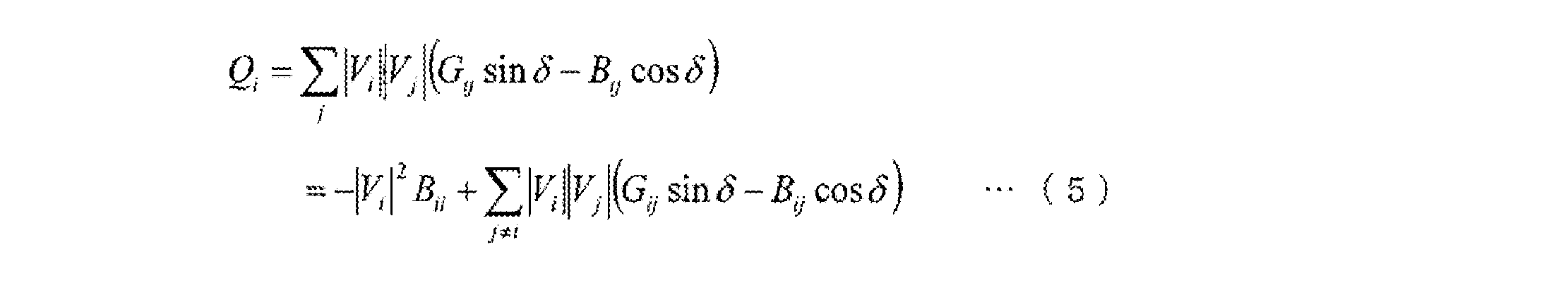


z: 観測値(センサやAMIで測定される電圧の大きさ、ノード注入電力、ブランチの電力状態)
h: 非線形関数(上記で定式化したPij, Qij,Pi,Qiおよび電圧Vi)
x: 状態変数(Vi、δij)
ν: 観測値に含まれるノイズ。観測値に含まれるノイズνは白色ノイズとみなす。
表現1.
電力系統の電力状態を制御するための電力系統制御システムで使用される第1制御装置であって、
電力系統の所定の各点の測定データを出力する複数のセンサ装置と、前記第1制御装置で算出される第1制御量または自装置内で算出される第2制御量のいずれかに基づいて所定の制御動作を行う第2制御装置とに通信ネットワークを介して接続されており、
前記複数のセンサ装置から取得する前記各測定データを用いて電力系統の第1電力状態を推定し、推定した第1電力状態に基づいて前記第1制御量を算出し、算出した前記第1制御量を前記第2制御装置に送信し、
前記各測定データのうち一部の測定データを取得できない場合には、前記各測定データのうち取得できた所定の測定データを用いて前記第1電力状態を推定する、
電力系統制御システムで使用される第1制御装置。
表現2.
前記所定の測定データに基づいて前記第1電力状態を推定するための第1電力状態推定モデルを前記所定の測定データの組合せ毎に予め生成し、
複数の前記第1電力状態推定モデルのうち実際に取得できた前記所定の測定データの組合せに一致する第1電力状態推定モデルと前記所定の測定データとを用いて前記第1電力状態を推定し、
推定した前記第1電力状態に基づいて前記第1制御量を算出し、算出した前記第1制御量を前記第2制御装置に送信する、
表現1に記載の電力系統制御システムで使用される第1制御装置。
表現3.
推定した前記第1電力状態に応じた前記第1制御量を算出するための第1制御量算出モデルを作成し、
推定した前記第1電力状態と前記第1制御量算出モデルとに基づいて前記第1制御量を算出し、
算出した前記第1制御量を前記第2制御装置に送信する、
表現2に記載の電力系統制御システムで使用される第1制御装置。
表現4.
前記第2制御装置は、所定の第1の場合に第1制御モードを実行し、前記第1制御モードでは、前記第1制御装置から受信する前記第1制御量に基づいて前記所定の制御動作を実行する、
表現3に記載の電力系統制御システムで使用される第1制御装置。
表現5.
前記第1電力状態推定モデルから生成される第2電力状態推定モデルと、前記第1制御量算出モデルから生成される第2制御量算出モデルとを前記第2制御装置に送信し、
前記第2制御装置は、受信する前記第2電力状態推定モデル及び前記第2制御量算出モデルを記憶し、所定の第2の場合に第2制御モードを実行し、前記第2制御モードでは、前記各センサ装置のうち所定のセンサ装置の測定データと前記第2電力状態推定モデルとに基づいて電力系統の第2電力状態を推定し、推定した前記第2電力状態と前記第2制御量算出モデルとに基づいて前記第2制御量を算出し、算出された前記第2制御量に基づいて前記所定の制御動作を実行する、
表現1~4のいずれかに記載の電力系統制御システムで使用される第1制御装置。
表現6.
前記所定の第2の場合とは、前記第2制御装置との通信状態が予め設定される所定値以下に低下したと判定した場合である、
表現5に記載の電力系統制御システムで使用される第1制御装置。
表現7.
前記各測定データと前記第1制御量とを対応づけて記憶しており、
それら記憶された前記各測定データ及び前記第1制御量を教師データとして、前記第2電力状態推定モデル及び前記前記第2制御量算出モデルを規定するためのパラメータをそれぞれ生成し、
それら生成したパラメータを前記第2電力状態推定モデル及び前記第2制御量算出モデルとして前記第2制御装置に送信する、
表現6に記載の電力系統制御システムで使用される第1制御装置。
表現8.
前記第2制御装置は、所定の第3の場合に第3制御モードを実行し、前記第3制御モードでは、前記各センサ装置のうち自装置のセンサ装置からの測定データと電力系統の構成を示す系統データとに基づいて前記第2制御量を算出し、算出された前記第2制御量に基づいて前記所定の制御動作を実行する、
表現4に記載の電力系統制御システムで使用される第1制御装置。
表現9.
前記所定の第3の場合とは、前記第2電力状態推定モデルに予め設定される有効期間が過ぎたと判定した場合である、
表現8に記載の電力系統制御システムで使用される第1制御装置。
表現10.
前記第2電力状態推定モデルには、電力需給状態の変動するタイミングに応じて前記有効期間が設定される、
表現9に記載の電力系統制御システムで使用される第1制御装置。
表現11.
前記第1制御装置の管理下に置かれていない他の第2制御装置の制御量を予測し、
その予測結果を用いて前記第1制御量を算出し、
算出された前記第1制御量を用いて前記第1電力状態を再度推定し、
再度推定された前記第1電力状態に基づいて前記第1制御量を再度算出する、
表現1に記載の電力系統制御システムで使用される第1制御装置。
表現12.
電力系統の電力状態を制御する電力系統制御システムで使用される第1制御装置を制御するための方法であって、
電力系統には、
測定データを出力する複数のセンサ装置と、
前記複数のセンサ装置から取得する前記各測定データを用いて電力系統の第1電力状態を推定し、推定した第1電力状態に基づいて第1制御量を算出し、算出した前記第1制御量を出力する第1制御装置と、
前記第1制御装置と通信可能に電力系統に配置され、前記第1制御装置で算出された第1制御量または自装置内で算出される第2制御量のいずれかに基づいて所定の制御動作を実行する少なくとも1つの第2制御装置と、
が設けられており、
前記第1制御装置は、前記各測定データのうち一部の測定データを取得できない場合には、前記各測定データのうち取得できた所定の測定データを用いて前記第1電力状態を推定する、
電力系統制御システムで使用される第1制御装置の制御方法。
表現13.
コンピュータを、電力系統の電力状態を制御するための電力系統制御システムで使用するための第1制御装置として機能させるためのコンピュータプログラムであって、
前記コンピュータは、電力系統の所定の各点の測定データを出力する複数のセンサ装置と、前記第1制御装置で算出される第1制御量または自装置内で算出される第2制御量のいずれかに基づいて所定の制御動作を行う第2制御装置とに通信ネットワークを介して接続されており、
前記複数のセンサ装置から取得する前記各測定データを用いて電力系統の第1電力状態を推定する機能と、
推定した第1電力状態に基づいて前記第1制御量を算出する機能と、
算出した前記第1制御量を前記第2制御装置に送信する機能と、
前記各測定データのうち一部の測定データを取得できない場合には、前記各測定データのうち取得できた所定の測定データを用いて前記第1電力状態を推定する機能と、
を前記コンピュータ上に実現するコンピュータプログラム。
Claims (15)
- 電力系統の電力状態を制御するための電力系統制御システムであって、
電力系統に配置され、測定データを出力する複数のセンサ装置と、
前記複数のセンサ装置から取得する前記各測定データを用いて電力系統の第1電力状態を推定し、推定した第1電力状態に基づいて第1制御量を算出し、算出した前記第1制御量を出力する第1制御装置と、
前記第1制御装置と通信可能に電力系統に配置され、前記第1制御装置で算出された第1制御量または自装置内で算出される第2制御量のいずれかに基づいて所定の制御動作を実行する少なくとも1つの第2制御装置と、
を備え、
前記第1制御装置は、前記各測定データのうち一部の測定データを取得できない場合には、前記各測定データのうち取得できた所定の測定データを用いて前記第1電力状態を推定する、
電力系統制御システム。
- 前記第1制御装置は、前記所定の測定データに基づいて前記第1電力状態を推定するための第1電力状態推定モデルを前記所定の測定データの組合せ毎に予め生成し、複数の前記第1電力状態推定モデルのうち実際に取得できた前記所定の測定データの組合せに一致する第1電力状態推定モデルと前記所定の測定データとを用いて前記第1電力状態を推定し、推定した前記第1電力状態に基づいて前記第1制御量を算出し、算出した前記第1制御量を前記第2制御装置に送信する、
請求項1に記載の電力系統制御システム。
- 前記第1制御装置は、推定した前記第1電力状態に応じた前記第1制御量を算出するための第1制御量算出モデルを作成し、推定した前記第1電力状態と前記第1制御量算出モデルとに基づいて前記第1制御量を算出し、算出した前記第1制御量を前記第2制御装置に送信する、
請求項2に記載の電力系統制御システム。
- 前記第2制御装置は、所定の第1の場合に第1制御モードを実行し、前記第1制御モードでは、前記第1制御装置から受信する前記第1制御量に基づいて前記所定の制御動作を実行する、
請求項3に記載の電力系統制御システム。
- 前記第1制御装置は、前記第1電力状態推定モデルから生成される第2電力状態推定モデルと、前記第1制御量算出モデルから生成される第2制御量算出モデルとを前記第2制御装置に送信し、
前記第2制御装置は、前記第1制御装置から受信する前記第2電力状態推定モデル及び前記第2制御量算出モデルを記憶し、所定の第2の場合に第2制御モードを実行し、前記第2制御モードでは、前記各センサ装置のうち所定のセンサ装置の測定データと前記第2電力状態推定モデルとに基づいて電力系統の第2電力状態を推定し、推定した前記第2電力状態と前記第2制御量算出モデルとに基づいて前記第2制御量を算出し、算出された前記第2制御量に基づいて前記所定の制御動作を実行する、
請求項1~4のいずれかに記載の電力系統制御システム。
- 前記所定の第2の場合とは、前記第1制御装置と前記第2制御装置との通信状態が予め設定される所定値以下に低下したと判定した場合である、
請求項5に記載の電力系統制御システム。
- 前記第1制御装置は、前記各測定データと前記第1制御量とを対応づけて記憶しており、それら記憶された前記各測定データ及び前記第1制御量を教師データとして、前記第2電力状態推定モデル及び前記前記第2制御量算出モデルを規定するためのパラメータをそれぞれ生成し、それら生成したパラメータを前記第2電力状態推定モデル及び前記第2制御量算出モデルとして前記第2制御装置に送信する、
請求項6に記載の電力系統制御システム。
- 前記第2制御装置は、所定の第3の場合に第3制御モードを実行し、前記第3制御モードでは、前記各センサ装置のうち自装置のセンサ装置からの測定データと電力系統の構成を示す系統データとに基づいて前記第2制御量を算出し、算出された前記第2制御量に基づいて前記所定の制御動作を実行する、
請求項4に記載の電力系統制御システム。
- 前記所定の第3の場合とは、前記第2電力状態推定モデルに予め設定される有効期間が過ぎたと判定した場合である、
請求項8に記載の電力系統制御システム。
- 前記第2電力状態推定モデルには、電力需給状態の変動するタイミングに応じて前記有効期間が設定される、
請求項9に記載の電力系統制御システム。
- 前記第1制御装置の管理下に置かれていない他の第2制御装置の制御量を予測し、その予測結果を用いて前記第1制御量を算出し、算出された前記第1制御量を用いて前記第1電力状態を再度推定し、再度推定された前記第1電力状態に基づいて前記第1制御量を再度算出する、
請求項1に記載の電力系統制御システム。
- 電力系統の電力状態を制御するための方法であって、
電力系統には、
測定データを出力する複数のセンサ装置と、
前記複数のセンサ装置から取得する前記各測定データを用いて電力系統の第1電力状態を推定し、推定した第1電力状態に基づいて第1制御量を算出し、算出した前記第1制御量を出力する第1制御装置と、
前記第1制御装置と通信可能に電力系統に配置され、前記第1制御装置で算出された第1制御量または自装置内で算出される第2制御量のいずれかに基づいて所定の制御動作を実行する少なくとも1つの第2制御装置と、
が設けられており、
前記第1制御装置は、前記各測定データのうち一部の測定データを取得できない場合には、前記各測定データのうち取得できた所定の測定データを用いて前記第1電力状態を推定する、
電力系統制御方法。
- 前記第1制御装置は、
前記所定の測定データに基づいて前記第1電力状態を推定するための第1電力状態推定モデルを前記所定の測定データの組合せ毎に予め生成し、
複数の前記第1電力状態推定モデルのうち実際に取得できた前記所定の測定データの組合せに一致する第1電力状態推定モデルと前記所定の測定データとを用いて前記第1電力状態を推定し、
推定した前記第1電力状態に応じた前記第1制御量を算出するための第1制御量算出モデルと推定した前記第1電力状態とに基づいて前記第1制御量を算出し、
算出した前記第1制御量を前記第2制御装置に送信する、
請求項12に記載の電力系統制御方法。
- 前記第2制御装置は、前記第1制御装置からデータを受信した最新のデータ受信時刻と前回のデータ受信時刻との差が所定の第1時間未満の場合に第1制御モードを実行し、前記第1制御モードでは、前記第1制御装置から受信する前記第1制御量に基づいて前記所定の制御動作を実行する、
請求項13に記載の電力系統制御方法。
- 前記第1制御装置は、前記第1電力状態推定モデルから生成される第2電力状態推定モデルと、前記第1制御量算出モデルから生成される第2制御量算出モデルとを前記第2制御装置に送信し、
前記第2制御装置は、
前記第1制御装置から受信する前記第2電力状態推定モデル及び前記第2制御量算出モデルを記憶し、
前記最新のデータ受信時刻と前記前回のデータ受信時刻との差が前記所定の第1時間以上になった場合に第2制御モードを実行し、前記第2制御モードでは、前記各センサ装置のうち所定のセンサ装置の測定データと前記第2電力状態推定モデルとに基づいて電力系統の第2電力状態を推定し、推定した前記第2電力状態と前記第2制御量算出モデルとに基づいて前記第2制御量を算出し、算出された前記第2制御量に基づいて前記所定の制御動作を実行する、
請求項14に記載の電力系統制御方法。
Priority Applications (5)
| Application Number | Priority Date | Filing Date | Title |
|---|---|---|---|
| PCT/JP2012/067615 WO2014010030A1 (ja) | 2012-07-10 | 2012-07-10 | 電力系統制御システム及び電力系統制御方法 |
| EP12880898.7A EP2874273B1 (en) | 2012-07-10 | 2012-07-10 | Power system control system, and power system control method |
| SI201231070T SI2874273T1 (sl) | 2012-07-10 | 2012-07-10 | Sistem za krmiljenje elektroenergetskega sistema in postopek krmiljenja elektroenergetskega sistema |
| JP2014524525A JP5809752B2 (ja) | 2012-07-10 | 2012-07-10 | 電力系統制御システム及び電力系統制御方法 |
| US14/402,366 US9774216B2 (en) | 2012-07-10 | 2012-07-10 | System and method for controlling power system |
Applications Claiming Priority (1)
| Application Number | Priority Date | Filing Date | Title |
|---|---|---|---|
| PCT/JP2012/067615 WO2014010030A1 (ja) | 2012-07-10 | 2012-07-10 | 電力系統制御システム及び電力系統制御方法 |
Publications (1)
| Publication Number | Publication Date |
|---|---|
| WO2014010030A1 true WO2014010030A1 (ja) | 2014-01-16 |
Family
ID=49915533
Family Applications (1)
| Application Number | Title | Priority Date | Filing Date |
|---|---|---|---|
| PCT/JP2012/067615 WO2014010030A1 (ja) | 2012-07-10 | 2012-07-10 | 電力系統制御システム及び電力系統制御方法 |
Country Status (5)
| Country | Link |
|---|---|
| US (1) | US9774216B2 (ja) |
| EP (1) | EP2874273B1 (ja) |
| JP (1) | JP5809752B2 (ja) |
| SI (1) | SI2874273T1 (ja) |
| WO (1) | WO2014010030A1 (ja) |
Cited By (15)
| Publication number | Priority date | Publication date | Assignee | Title |
|---|---|---|---|---|
| JP2014027810A (ja) * | 2012-07-27 | 2014-02-06 | Kyushu Electric Power Co Inc | 遠隔制御機能を有する分散型電源対応自動電圧調整器及びその制御方法 |
| CN104268655A (zh) * | 2014-09-30 | 2015-01-07 | 国家电网公司 | 一种输电线路山火预警方法 |
| CN104852389A (zh) * | 2015-05-27 | 2015-08-19 | 西安工程大学 | 一种提高系统暂态稳定性的静止无功补偿器控制装置 |
| WO2015151143A1 (ja) * | 2014-03-31 | 2015-10-08 | 株式会社日立製作所 | 電力系統の制御指令装置 |
| JP5962770B2 (ja) * | 2012-12-07 | 2016-08-03 | 株式会社日立製作所 | 電力系統制御システム及び電力系統制御方法 |
| JP2016214036A (ja) * | 2015-05-13 | 2016-12-15 | 富士電機株式会社 | 制御システム、配信方法、及びプログラム |
| JP2017011529A (ja) * | 2015-06-23 | 2017-01-12 | 株式会社リコー | 無線センサネットワークシステム |
| JP2018011391A (ja) * | 2016-07-12 | 2018-01-18 | 富士電機株式会社 | 電圧監視制御装置 |
| US20180128862A1 (en) * | 2015-06-11 | 2018-05-10 | Hitachi, Ltd. | Autonomous Monitoring System for Power Distribution System, Distribution System Monitoring Method, and First Device Used in Autonomous Monitoring System for Power Distribution System |
| JP2018098986A (ja) * | 2016-12-16 | 2018-06-21 | 株式会社日立製作所 | 電力系統の状態推定装置および状態推定方法 |
| JP2019505799A (ja) * | 2016-01-26 | 2019-02-28 | ゼネラル エレクトリック テクノロジー ゲゼルシャフト ミット ベシュレンクテル ハフツングGeneral Electric Technology GmbH | 電力ネットワーク内の振動 |
| CN110515333A (zh) * | 2019-08-28 | 2019-11-29 | 国家电网有限公司 | 一种智能物联端子箱、泛在电力物联网平台及其应用方法 |
| JP2020042692A (ja) * | 2018-09-13 | 2020-03-19 | 株式会社日立製作所 | プラント診断用データ生成システムおよび方法 |
| JP2022532091A (ja) * | 2019-05-07 | 2022-07-13 | ヒタチ・エナジー・スウィツァーランド・アクチェンゲゼルシャフト | 動的予測、集約、および妥当性確認のための機器および方法 |
| WO2022211193A1 (ko) * | 2021-03-31 | 2022-10-06 | 한국에너지기술연구원 | 분산 전원의 성능 및 신뢰성 테스트 시스템 및 그 방법 |
Families Citing this family (8)
| Publication number | Priority date | Publication date | Assignee | Title |
|---|---|---|---|---|
| JP6281817B2 (ja) * | 2014-03-14 | 2018-02-21 | パナソニックIpマネジメント株式会社 | 需給制御方法、および、需給制御装置 |
| DE102016114254A1 (de) * | 2016-08-02 | 2018-02-08 | Wobben Properties Gmbh | Verfahren zum Ausgeben eines Reglersollwerts für einen Energieerzeuger sowie Vorrichtung dazu und System damit |
| WO2019150586A1 (ja) * | 2018-02-05 | 2019-08-08 | 三菱電機株式会社 | 集中電圧制御装置および集中電圧制御システム |
| US11527896B2 (en) * | 2018-05-09 | 2022-12-13 | Nec Corporation | Control apparatus, power management system, control method, and non-transitory storage medium |
| CN110519323A (zh) * | 2018-05-21 | 2019-11-29 | 极光物联科技(深圳)有限公司 | 能源物联网设备、能源物联网系统及其操作方法 |
| FR3084168B1 (fr) * | 2018-07-18 | 2021-08-27 | Electricite De France | Procede et systeme de determination d'un etat en tension d'un reseau de distribution basse tension au niveau d'au moins un poste de transformation |
| US11467616B2 (en) * | 2018-11-09 | 2022-10-11 | General Electric Company | System and method for controlling operation of an energy generation and storage system |
| CN110647128B (zh) * | 2019-10-18 | 2022-09-20 | 南京泰鸿信息科技有限公司 | 一种变电站综合自动化监控管理系统 |
Citations (6)
| Publication number | Priority date | Publication date | Assignee | Title |
|---|---|---|---|---|
| JPH06269123A (ja) * | 1993-03-12 | 1994-09-22 | Hitachi Ltd | 広域電力系統緊急監視方法及び緊急制御方法及び装置 |
| JPH0974679A (ja) * | 1995-09-08 | 1997-03-18 | Hitachi Ltd | 電力系統安定化方法および装置 |
| JP2007288877A (ja) | 2006-04-14 | 2007-11-01 | Hitachi Ltd | 複数の分散型電源が連系された配電系統の電力品質維持支援方法及び電力品質維持支援システム |
| JP2008118799A (ja) * | 2006-11-06 | 2008-05-22 | Toshiba Corp | 配電系統最適運用システムと方法、およびプログラム |
| JP2008154418A (ja) * | 2006-12-20 | 2008-07-03 | Hitachi Ltd | 配電系統の状態推定装置、状態推定方法及びそのプログラム |
| JP2011217581A (ja) | 2010-04-02 | 2011-10-27 | Mitsubishi Electric Corp | 線路用自動電圧調整装置 |
Family Cites Families (23)
| Publication number | Priority date | Publication date | Assignee | Title |
|---|---|---|---|---|
| US4689752A (en) * | 1983-04-13 | 1987-08-25 | Niagara Mohawk Power Corporation | System and apparatus for monitoring and control of a bulk electric power delivery system |
| JP3249275B2 (ja) * | 1993-12-02 | 2002-01-21 | 株式会社東芝 | 配電系統における送出電圧調整処理装置 |
| JP4119077B2 (ja) * | 1999-07-28 | 2008-07-16 | 関西電力株式会社 | 電力系統の周波数安定化装置 |
| US8108184B2 (en) * | 2004-01-15 | 2012-01-31 | Bruce Fardanesh | Methods and systems for power systems analysis: a non-iterative state solver/estimator for power systems operation and control |
| JP4148208B2 (ja) | 2004-09-15 | 2008-09-10 | 株式会社日立製作所 | 配電系統の状態推定装置,方法及びプログラム |
| EP1783499A1 (en) * | 2005-11-08 | 2007-05-09 | ABB Technology AG | Method and apparatus for verifying the accuracy of state estimation calculations |
| US20090040029A1 (en) * | 2006-08-10 | 2009-02-12 | V2Green, Inc. | Transceiver and charging component for a power aggregation system |
| US20080177678A1 (en) * | 2007-01-24 | 2008-07-24 | Paul Di Martini | Method of communicating between a utility and its customer locations |
| JP2009065788A (ja) * | 2007-09-06 | 2009-03-26 | Univ Of Ryukyus | 配電系統の最適電圧制御装置 |
| CN101383511B (zh) * | 2008-10-10 | 2010-08-04 | 清华大学 | 基于数据采集系统量测数据的电力系统状态估计方法 |
| JP2010226942A (ja) | 2009-02-26 | 2010-10-07 | Sanyo Electric Co Ltd | 系統連系装置、系統連系システム及び配電システム |
| ES2382786B1 (es) * | 2009-03-17 | 2013-05-07 | Acciona Windpower S.A. | Metodo y sistema de control de tension de una central de generacion electrica y parque eolico |
| US20120022713A1 (en) * | 2010-01-14 | 2012-01-26 | Deaver Sr Brian J | Power Flow Simulation System, Method and Device |
| JP5501796B2 (ja) * | 2010-02-24 | 2014-05-28 | 富士通株式会社 | 配電網推定装置および配電網推定方法 |
| US8600572B2 (en) * | 2010-05-27 | 2013-12-03 | International Business Machines Corporation | Smarter-grid: method to forecast electric energy production and utilization subject to uncertain environmental variables |
| JP5427762B2 (ja) * | 2010-12-16 | 2014-02-26 | 株式会社日立製作所 | 電力変換装置、電力変換装置の制御装置及び電力変換装置の制御方法 |
| US20120310559A1 (en) * | 2011-05-31 | 2012-12-06 | Cisco Technology, Inc. | Distributed data collection for utility grids |
| WO2013025144A1 (en) * | 2011-08-15 | 2013-02-21 | Telefonaktiebolaget Lm Ericsson (Publ) | A method and an apparatus in a user equipment for controlling transmission power of the user equipment |
| JP5615785B2 (ja) * | 2011-09-26 | 2014-10-29 | 株式会社日立製作所 | 電力系統状態推定装置およびそれを用いた電力系統システム |
| US9863985B2 (en) * | 2012-04-13 | 2018-01-09 | Regents Of The University Of Minnesota | State estimation of electrical power networks using semidefinite relaxation |
| JP5984601B2 (ja) * | 2012-09-21 | 2016-09-06 | 株式会社日立製作所 | 系統制御装置および系統制御方法 |
| JP5727063B1 (ja) * | 2014-02-27 | 2015-06-03 | 株式会社東芝 | エネルギー管理装置、エネルギー管理システム、エネルギー管理方法およびプログラム |
| JP6281817B2 (ja) * | 2014-03-14 | 2018-02-21 | パナソニックIpマネジメント株式会社 | 需給制御方法、および、需給制御装置 |
-
2012
- 2012-07-10 US US14/402,366 patent/US9774216B2/en active Active
- 2012-07-10 WO PCT/JP2012/067615 patent/WO2014010030A1/ja active Application Filing
- 2012-07-10 JP JP2014524525A patent/JP5809752B2/ja active Active
- 2012-07-10 EP EP12880898.7A patent/EP2874273B1/en active Active
- 2012-07-10 SI SI201231070T patent/SI2874273T1/sl unknown
Patent Citations (6)
| Publication number | Priority date | Publication date | Assignee | Title |
|---|---|---|---|---|
| JPH06269123A (ja) * | 1993-03-12 | 1994-09-22 | Hitachi Ltd | 広域電力系統緊急監視方法及び緊急制御方法及び装置 |
| JPH0974679A (ja) * | 1995-09-08 | 1997-03-18 | Hitachi Ltd | 電力系統安定化方法および装置 |
| JP2007288877A (ja) | 2006-04-14 | 2007-11-01 | Hitachi Ltd | 複数の分散型電源が連系された配電系統の電力品質維持支援方法及び電力品質維持支援システム |
| JP2008118799A (ja) * | 2006-11-06 | 2008-05-22 | Toshiba Corp | 配電系統最適運用システムと方法、およびプログラム |
| JP2008154418A (ja) * | 2006-12-20 | 2008-07-03 | Hitachi Ltd | 配電系統の状態推定装置、状態推定方法及びそのプログラム |
| JP2011217581A (ja) | 2010-04-02 | 2011-10-27 | Mitsubishi Electric Corp | 線路用自動電圧調整装置 |
Non-Patent Citations (1)
| Title |
|---|
| See also references of EP2874273A4 |
Cited By (24)
| Publication number | Priority date | Publication date | Assignee | Title |
|---|---|---|---|---|
| JP2014027810A (ja) * | 2012-07-27 | 2014-02-06 | Kyushu Electric Power Co Inc | 遠隔制御機能を有する分散型電源対応自動電圧調整器及びその制御方法 |
| JP5962770B2 (ja) * | 2012-12-07 | 2016-08-03 | 株式会社日立製作所 | 電力系統制御システム及び電力系統制御方法 |
| JPWO2014087539A1 (ja) * | 2012-12-07 | 2017-01-05 | 株式会社日立製作所 | 電力系統制御システム及び電力系統制御方法 |
| US10361560B2 (en) | 2014-03-31 | 2019-07-23 | Hitachi, Ltd. | Power system control instruction device and method for controlling a voltage of a power system |
| WO2015151143A1 (ja) * | 2014-03-31 | 2015-10-08 | 株式会社日立製作所 | 電力系統の制御指令装置 |
| JPWO2015151143A1 (ja) * | 2014-03-31 | 2017-04-13 | 株式会社日立製作所 | 電力系統の制御指令装置 |
| CN104268655A (zh) * | 2014-09-30 | 2015-01-07 | 国家电网公司 | 一种输电线路山火预警方法 |
| CN104268655B (zh) * | 2014-09-30 | 2016-05-25 | 国家电网公司 | 一种输电线路山火预警方法 |
| JP2016214036A (ja) * | 2015-05-13 | 2016-12-15 | 富士電機株式会社 | 制御システム、配信方法、及びプログラム |
| CN104852389A (zh) * | 2015-05-27 | 2015-08-19 | 西安工程大学 | 一种提高系统暂态稳定性的静止无功补偿器控制装置 |
| US20180128862A1 (en) * | 2015-06-11 | 2018-05-10 | Hitachi, Ltd. | Autonomous Monitoring System for Power Distribution System, Distribution System Monitoring Method, and First Device Used in Autonomous Monitoring System for Power Distribution System |
| JP2017011529A (ja) * | 2015-06-23 | 2017-01-12 | 株式会社リコー | 無線センサネットワークシステム |
| US11025065B2 (en) | 2016-01-26 | 2021-06-01 | General Electric Technology Gmbh | Oscillations in electrical power networks |
| JP2019505799A (ja) * | 2016-01-26 | 2019-02-28 | ゼネラル エレクトリック テクノロジー ゲゼルシャフト ミット ベシュレンクテル ハフツングGeneral Electric Technology GmbH | 電力ネットワーク内の振動 |
| JP2018011391A (ja) * | 2016-07-12 | 2018-01-18 | 富士電機株式会社 | 電圧監視制御装置 |
| WO2018110082A1 (ja) * | 2016-12-16 | 2018-06-21 | 株式会社日立製作所 | 電力系統の状態推定装置および状態推定方法 |
| JP2018098986A (ja) * | 2016-12-16 | 2018-06-21 | 株式会社日立製作所 | 電力系統の状態推定装置および状態推定方法 |
| US11042134B2 (en) | 2016-12-16 | 2021-06-22 | Hitachi, Ltd. | Power system status estimation device and status estimation method |
| JP2020042692A (ja) * | 2018-09-13 | 2020-03-19 | 株式会社日立製作所 | プラント診断用データ生成システムおよび方法 |
| JP7002427B2 (ja) | 2018-09-13 | 2022-01-20 | 株式会社日立製作所 | プラント診断用データ生成システムおよび方法 |
| JP2022532091A (ja) * | 2019-05-07 | 2022-07-13 | ヒタチ・エナジー・スウィツァーランド・アクチェンゲゼルシャフト | 動的予測、集約、および妥当性確認のための機器および方法 |
| JP7198376B2 (ja) | 2019-05-07 | 2022-12-28 | ヒタチ・エナジー・スウィツァーランド・アクチェンゲゼルシャフト | 動的予測、集約、および妥当性確認のための機器および方法 |
| CN110515333A (zh) * | 2019-08-28 | 2019-11-29 | 国家电网有限公司 | 一种智能物联端子箱、泛在电力物联网平台及其应用方法 |
| WO2022211193A1 (ko) * | 2021-03-31 | 2022-10-06 | 한국에너지기술연구원 | 분산 전원의 성능 및 신뢰성 테스트 시스템 및 그 방법 |
Also Published As
| Publication number | Publication date |
|---|---|
| US9774216B2 (en) | 2017-09-26 |
| EP2874273A4 (en) | 2016-03-30 |
| SI2874273T1 (sl) | 2017-11-30 |
| EP2874273B1 (en) | 2017-09-06 |
| EP2874273A1 (en) | 2015-05-20 |
| JPWO2014010030A1 (ja) | 2016-06-20 |
| JP5809752B2 (ja) | 2015-11-11 |
| US20150142187A1 (en) | 2015-05-21 |
Similar Documents
| Publication | Publication Date | Title |
|---|---|---|
| WO2014010030A1 (ja) | 電力系統制御システム及び電力系統制御方法 | |
| US11201491B2 (en) | Method for balancing frequency instability on an electric grid using networked distributed energy storage systems | |
| US10389126B2 (en) | Method and apparatus for damping power oscillations on an electrical grid using networked distributed energy storage systems | |
| US9489701B2 (en) | Adaptive energy management system | |
| US9705332B2 (en) | Energy storage systems | |
| JP5355147B2 (ja) | 排出係数算定器および排出係数算定方法 | |
| JP6402731B2 (ja) | 電力需給予測システム、電力需給予測方法および電力需給予測プログラム | |
| JP5962770B2 (ja) | 電力系統制御システム及び電力系統制御方法 | |
| JP2015035941A (ja) | エネルギー管理システム、エネルギー管理方法及びコンピュータプログラム | |
| JP5970146B1 (ja) | 太陽光発電装置を含む電力系統の制御方法及び制御システム | |
| JP2015109737A (ja) | 配電系統監視装置 | |
| JP2016019358A (ja) | 需要予測装置、コンピュータプログラム、スマートメーター及び蓄電装置 | |
| JP6189987B2 (ja) | 管理システム、制御装置、及び制御方法 | |
| JP2017221040A (ja) | 配電系統監視装置 | |
| WO2013172431A1 (ja) | 電力管理装置、電力管理システム及び電力管理方法 | |
| US20180034318A1 (en) | Method for controlling an electric power distribution grid | |
| KR20150037410A (ko) | 분산 전원의 스케쥴링 및 실시간 제어를 통한 빌딩 에너지 관리 장치 | |
| JP5752069B2 (ja) | 電力制御システム | |
| JP5944225B2 (ja) | 警報提示装置及び警報提示方法 | |
| JP5847650B2 (ja) | エネルギー管理システム、サーバ装置、エネルギー管理方法およびプログラム | |
| EP3574560A1 (en) | Techniques for managing resource consumption for demand-based metering | |
| JP2013192364A (ja) | コミュニティエネルギー管理システムおよびコミュニティエネルギー管理方法 | |
| GB2490882A (en) | Nodal utility data processing system | |
| JP5893507B2 (ja) | 警報提示装置及び警報提示方法 | |
| JP2017209013A (ja) | 管理システム、制御装置、及び制御方法 |
Legal Events
| Date | Code | Title | Description |
|---|---|---|---|
| 121 | Ep: the epo has been informed by wipo that ep was designated in this application |
Ref document number: 12880898 Country of ref document: EP Kind code of ref document: A1 |
|
| ENP | Entry into the national phase |
Ref document number: 2014524525 Country of ref document: JP Kind code of ref document: A |
|
| REEP | Request for entry into the european phase |
Ref document number: 2012880898 Country of ref document: EP |
|
| WWE | Wipo information: entry into national phase |
Ref document number: 2012880898 Country of ref document: EP |
|
| WWE | Wipo information: entry into national phase |
Ref document number: 14402366 Country of ref document: US |
|
| NENP | Non-entry into the national phase |
Ref country code: DE |